Article

Assessing Vulnerabilities in Line Length Parameterization and the Per-Unit-Length Paradigm for Phase Modulation and Figure-of-Merit Evaluation in 60 GHz Liquid Crystal Phase Shifters

by
Jinfeng Li
1,2,3,* and
Haorong Li
1
1
Beijing Key Laboratory of Millimeter Wave and Terahertz Technology, School of Integrated Circuits and Electronics, Beijing Institute of Technology, Beijing 100081, China
2
Advanced Research Institute of Multidisciplinary Science, Beijing Institute of Technology, Beijing 100081, China
3
Department of Electrical and Electronic Engineering, Imperial College London, London SW7 2AZ, UK
*
Author to whom correspondence should be addressed.
Symmetry 2024, 16(10), 1261; https://doi.org/10.3390/sym16101261
Submission received: 27 August 2024 / Revised: 19 September 2024 / Accepted: 24 September 2024 / Published: 25 September 2024
(This article belongs to the Special Issue Feature Papers in Section "Engineering and Materials" 2024)

Abstract

:
The figure-of-merit (FoM) is a crucial metric in evaluating liquid crystal (LC) phase shifters, significantly influencing the selection of superior device candidates. This paper identifies, for the first time, a fundamental limitation in the widely-used High-Frequency Structure Simulator (HFSS), a closed-source commercial tool, when modeling reconfigurable delay line phase shifters (RDLPS) based on LC at millimeter-wave (mmW) frequencies for Beyond 5G (B5G) and Sixth-Generation (6G) applications. Specifically, the study reveals unreliable predictions of differential phase shifts (DPS) when using the line length parameterization (LLP) approach, with an accuracy of only 47.22%. These LLP-induced inaccuracies lead to misleading FoM calculations, potentially skewing comparative analyses against phase shifters implemented with different geometries or advanced technologies. Additionally, the per-unit-length (PUL) paradigm, commonly employed by microwave circuit engineers for evaluating and optimizing microwave transmission line designs, is also found to have limitations in the context of mmW RDLPS based on LC. The PUL methodology underestimates the FoM by 1.38206°/dB for an LC coaxial RDLPS at 60 GHz. These findings underscore a critical symmetry implication, where the assumed symmetry in phase shift response is violated, resulting in inconsistent performance assessments. To address these challenges, a remediation strategy based on a scenario-based “Length-for-π” (LFP) framework is proposed, offering more accurate performance characterization and enabling better-informed decision-making in mmW phase shifter design.

1. Introduction

Phase shifters [1,2,3,4,5] are the heartbeats of phased array antennas [6,7,8] that underpin dynamic beam steering of electromagnetic waves, in particular, the microwave (MW) and millimeter-wave (mmW) for Fifth-Generation (5G), Beyond 5G (B5G), and toward Sixth-Generation (6G) ultra-capacity wireless networks. Besides the proliferation of data communication applications [9], phase-shifting-based beam steering at MW and mmW also finds equivalently important applications in parametric sensing [10] and wireless power transmission [11,12]. From its inception over half a century ago, liquid crystal display (LCD) [13] has since witnessed enduring commercial successes in digitally representing the colorful world at optical wavelengths. New prototypes launched in the early 2000s [14,15,16], microwave (MW) and millimeter-wave (mmW) engineered liquid crystals (LC) and their enabled reconfigurable devices are leading the tsunami of newer reconfigurable technologies research [17,18,19], a testament of engineering fusing with material sciences [20,21]. In the last two decades, conventional reconfigurable delay line phase shifters (RDLPS) [22] that were realized in unconventional ways, e.g., in liquid crystals (LC) [23,24,25,26], are actively shaping the next-generation paradigm of high-spatial-resolution beam-steering phased array antennas thanks to the inherently continuous tunability of the LC dielectric dipolar moment [27,28] and hence the effective dielectric constant [29] and ultimately, the wave speed stepless manipulation. Nowadays, the LC-enabled phase shifters have become popular state-of-the-art techniques in staying on track for coping with the ever-increasing demands of post-5G and beyond (6G) ecosystems, thanks to their achievable fine-tuning resolution (the bespoke identity that is theoretically analog), the advantage of which is not afforded by classical switches-based solutions, e.g., semiconductor p-i-n diodes [30] and RF MEMS (radio frequency micro-electromechanical systems) [8,22].
Despite the market dominance of LCD at optical wavelengths, the next-era technology of LC-based MW and mmW devices has not yet been widely produced commercially [18] for radically shifting the paradigm of civil applications (or serving defense industries). Besides targeting the performance maximization for potentially superseding conventional switches-based solutions, it is of equal importance to develop general standardized products beyond the in-house application-specific product. To this end, efforts to facilitate this roadmap will be highly desirable. Conventionally, cross-section structuring has extensively been investigated, leading to a host of LC-combined MW device topologies, e.g., inverted microstrip [31] (as revised from microstrip transmission lines [32,33]), coplanar, and the revised versions (semi-shielded [34] and fully symmetric [35]), harnessing vias-free solutions [25], with vias edition [36], defected grounding [37], etc. With the evolution of the geometry and manufacturing optimizations, the insertion losses of the LC-enabled phase shifters (0–π) were recently reduced from 10 dB [38] to 4 dB [34] at 66 GHz, driving a huge leap in the achievable figure-of-merit (FoM) that has been raised from 18°/dB to 45°/dB at 66 GHz. The foundational theories of the phase-shifting mechanism and dissipative loss are mathematically specified in our past works on coaxial [25,29], inverted microstrip [31], fully-shielded [34], and semi-shielded [35] coplanar structures combined with LC. However, the understanding of FoM’s dependency is patchy and lacks a unified framework. Particularly, its dependency on the line length is studied sparingly.
Conventionally, a thoughtfully designed cross-section study suffices to define the electromagnetic wave propagating pattern (mode), and thus, this method has changed very little over the past few decades for MW transmission line devices’ design and characterization computationally. Rather, little attention is paid to the line length domain, a critical geometry factor that translates the cross-sessional anisotropy (due to shape anisotropy of LC molecules) into a phase shifter device’s functioning practice of either 0 to π shift (for reconfigurable intelligence surfaces [39]), or 0 to 2π shift (for phased array antennas [40,41] and oscillators [42]). As such, rethinking the line length effect is arguably adding a new dimension to the current knowledge of LC-based variable phase shifters at MW, mmW, and terahertz (THz).
In the past decade, the lifecycle of LC MW and mmW phase shifter production has been run through, wherein our research activities intersect with various development phases from design [35], fabrication and assembling [34], to final polishing and optimisation [31], delivering decently performed phase-shifting functionality with reliability and durability unimpaired. During this journey, various insertion loss-calming measures [25,31,43] have been proposed and carried out to address impending application issues and challenges to meet the stringent power envelopes of the existing phased array beam steering devices. By way of illustration, our recent work reported in [43] leverages symmetry in the boundary condition (and hence the homogenization of the electromagnetic field distribution) for enhanced FoM of an LC phase shifter at 60 GHz.
In advance of real-world deployment, one of the effective methods in widening the phase shifting range of LC-based phase shifters is increasing the line length of the tunable transmission line by design. However, only a handful of research concerns the line length dependency, more specifically, little attempt is made to understand the limitation of existing design tools of wide industry and academic deployment, e.g., the full wave simulator HFSS (high-frequency structure simulator).
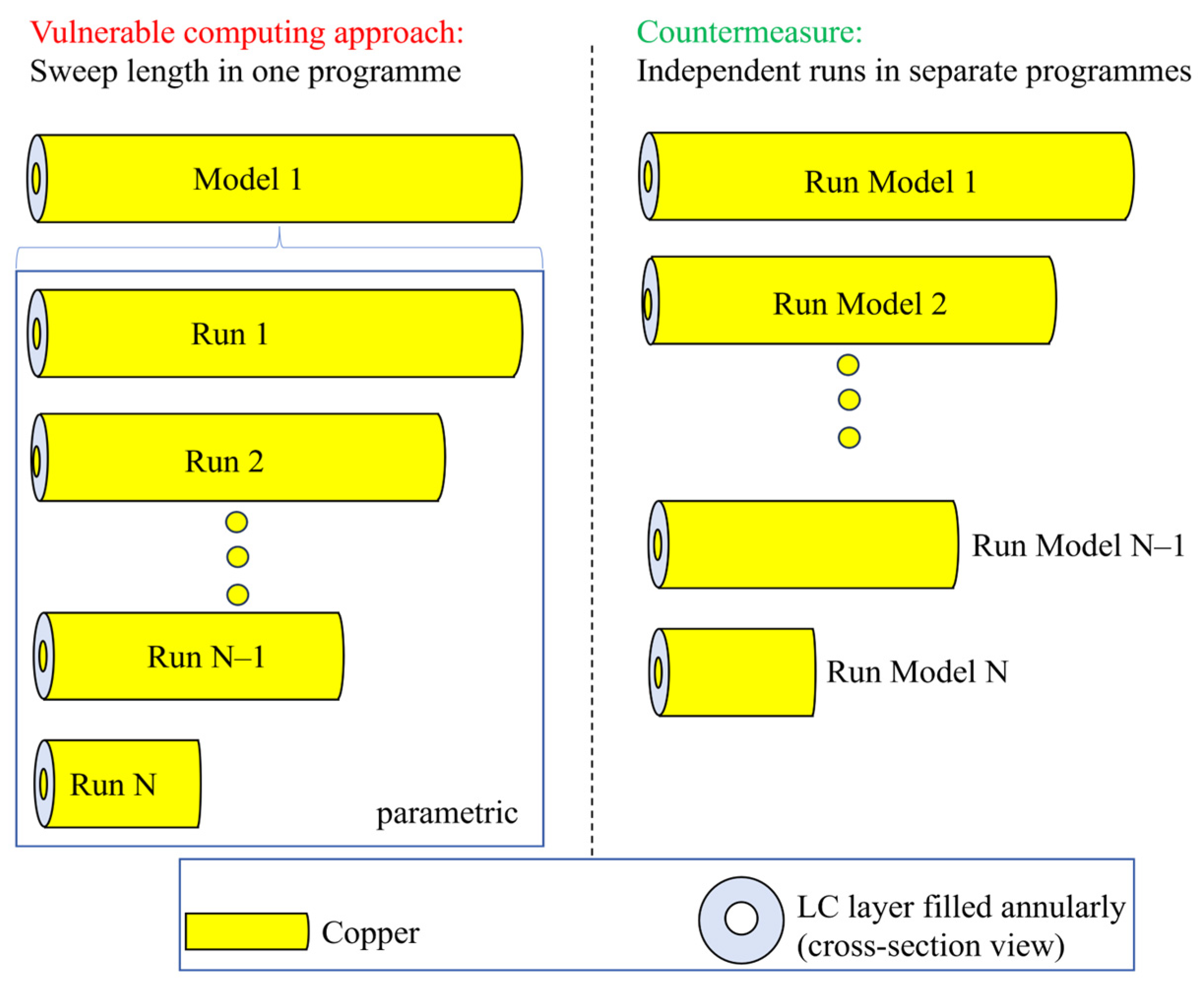
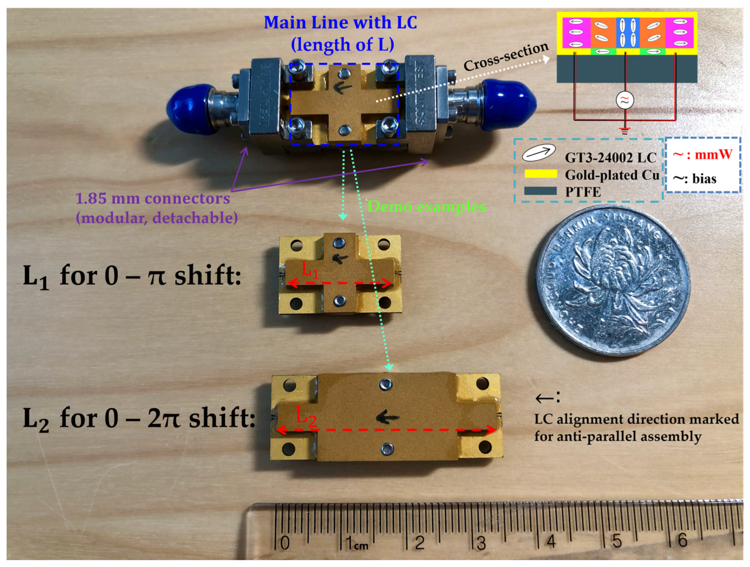
As such, besides project-based research that exploits the feasibility of LC in combining with RF/MW tunable components, education-oriented rethinking is thematically anchored in this work as another primary focus. By numerical testing and numerical experiments conducted in this paper for an LC-filled coaxial phase shifter operating at 60 GHz mmW (Figure 1), a noticeable drawback from HFSS is observed, i.e., the S-parameters prediction is vulnerable to phase errors when parameterizing with the line length of the device run in the same model (as per Figure 2 on the left for sweeping the line length from design 1 to design N solved in a single program, i.e., one model solving N designs). This is especially the case with the line length-dependent phase shifters, e.g., 0 to 180° (π) or 0 to 360° (2π) shifting ones as illustrated in our experimental demos shown in Figure 3. The two experimental prototypes feature the lengths for π and 2π shifting capability, respectively, whereas other intermediate line lengths have yet to be investigated. The countermeasure for the vulnerability is proposed as per Figure 2 on the right, wherein the models of diverse line lengths are programmed and solved individually, i.e., N models solving N designs. The chief difference and underlying mechanisms for these two paradigms will be elaborated in Section 2.
As a physical manifestation of the convergence of LC and RDLPS, the experimental prototype shown in Figure 3 is edge-mount connected with a pair of 1.85 mm connectors. Notably, the delay (in phase or time) is tunable (by the bias voltage from 0 V to the saturated one), while the maximum delay is fixed (by the length of the device). The fabrication and assembly details of the prototype are explicitly provided in our past work [34], wherein interested readers can probe the detailed manufacturing procedures.
In the remainder of this paper, Section 2 deals with an observed vulnerability of the line length parameterization approach run on a single model (Section 2.1), with the error rate quantified statistically for the first time (Section 2.2). The faulty rate indicates a non-negligible part that challenges the existing knowledge, whereas far less work has been devoted to reporting and understanding the phenomenon, which motivates us to conduct a deep dive into the problem and provide generalized remediating strategies for resolving the LLP anomaly that cannot be handled by the vulnerable single-model programming. In Section 2.2, the root cause of the LLP vulnerability is investigated and revealed for generalization purposes. A remediation approach is suggested, with the computational cost (time and memory) identified in Section 2.3 for the vulnerability-free method. Section 3 furthers the study into another vulnerability spotted in the usage of the mainstream per-unit-length (PUL) framework in assessing the FoM performance of devices in diverse line lengths. A remediated paradigm, namely “Length-for-π” (LFP) is proposed and compared with the vulnerable PUL one. Section 4 concludes the implications and outlines the future research direction.

2. Materials and Methods

2.1. Vulnerabilities of Line Length Parameterized (LLP) on a Single Model

The inherent flaws in the full-wave computation were spotted when evaluating the FoM (figure-of-merit, the main performance index) of LC-filled coaxial delay lines of different line lengths but under the optimal cross-sectional size [25] (i.e., fixing the LC layer thickness of T L C = 0.34876 mm annularly for the core line’s diameter measuring 0.23 mm). More specifically, they were spotted when running the line length parameterization (LLP) of a fixed coaxial cross-section in a single HFSS model (version 2022 R1), as illustrated in Figure 2 (on the left) for the vulnerable one observed as compared with Figure 2 (on the right) for the secure approach. The cross-section geometry is designed with the single-mode operation assured, i.e., free of higher-order modes and their coupling effects. Copper (i.e., with finite conductivity) is used for the core line as well as the housing conductor (ground), while the metal surface roughness is not considered to rule out the additional uncertainty.
The computational results are obtained based on the convergence threshold (ΔS) below 0.02 (absolute value). The input and output ports (wave ports) are strategically renormalized to 50 Ω for post-processing of the S-parameters data (forward transmission phase and amplitude). The differential phase shift (DPS) of interest (main functionality of a phase shifter device) is obtained by deducting the cumulative phase (cang deg) of the two extreme biasing states for GT3-24002 grade of LC (leading to the LC permittivity of 2.754 and 3.3 [25] at 60 GHz, respectively). Regarding the forward transmission amplitude, the maximum insertion loss (60 GHz) is obtained at one of the extreme permittivity states of 2.754, where the loss tangent peaks intrinsically [25].
The parameter scanning of the length is conducted from 1 mm to 36 mm (with the step of 1 mm), in addition to the individual points of 15.92 mm and 31.84 mm, which are, rather, run separately for a maximally achievable shift of 180° (π) and 360° (2π), respectively. The parametric analysis comprised 38 distinct line-length scenarios. For each line length model, broadband adaptive meshing refinement was conducted across the frequency range of 54 GHz to 66 GHz, utilizing a quad-core workstation with 8 logical processors. Specifically, adaptive meshing refinement was performed iteratively at frequencies of 54 GHz, 55.5 GHz, 57 GHz, 58.5 GHz, 60 GHz, 61.5 GHz, 63 GHz, and 66 GHz (with up to 8 frequencies solved in parallel) to achieve broadband solutions over the 54 GHz to 66 GHz range for both tuning states of the LC. The complete frequency range was covered by interpolating frequency sweeps within a specified error tolerance, once the field solution had converged (with a maximum delta S of less than 0.02). Integration lines are properly defined at the input and output wave ports, for the sake of securing the targeted TEM (Transverse Electromagnetic) unimodal excitation and reliable propagation modal analysis. It is important to note that integration lines can only be defined once per program; therefore, the same pair of integration lines was applied to all parametric runs with varying line lengths (Figure 2 on the left), ranging from 1 mm to 36 mm in this study.
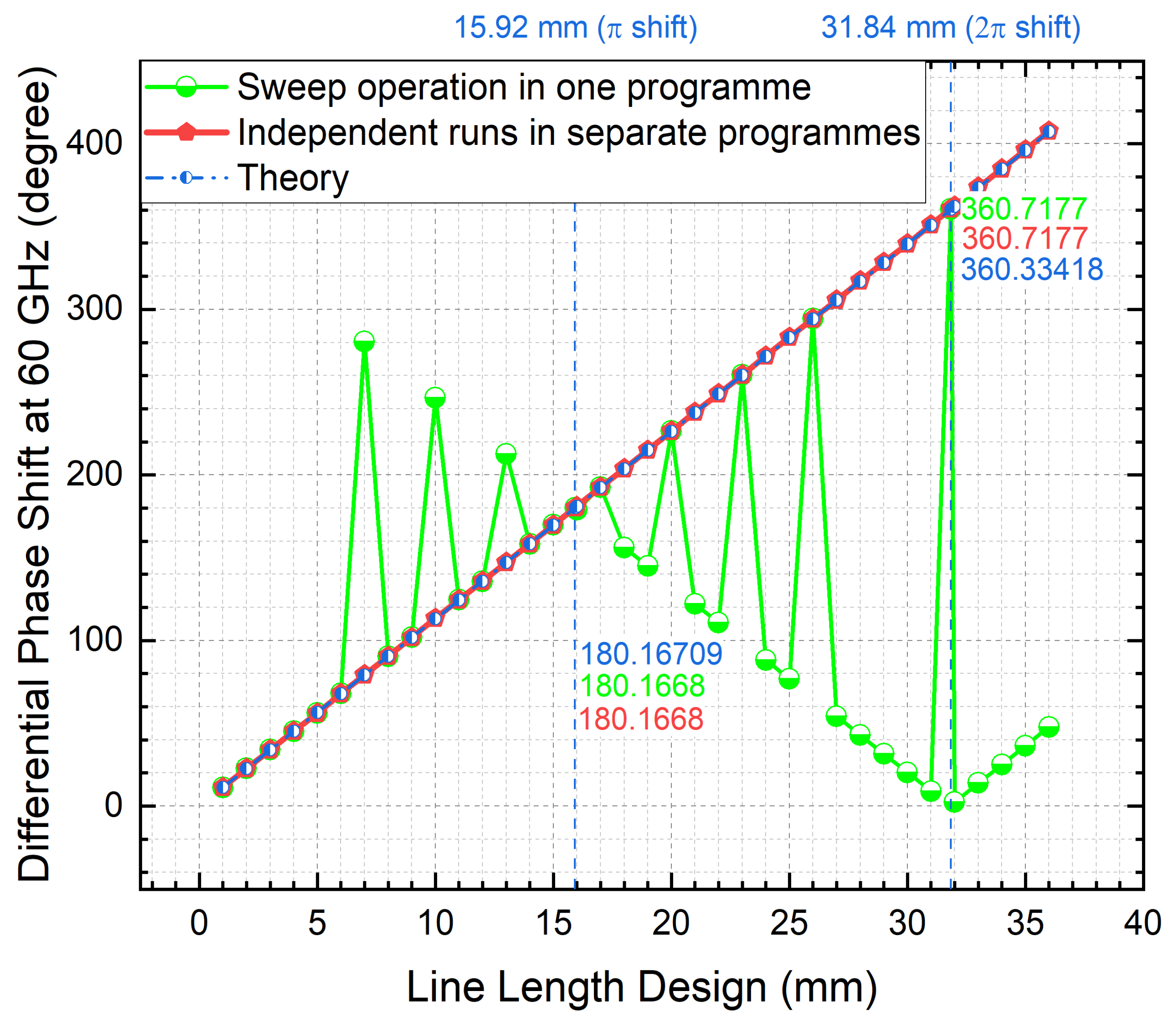
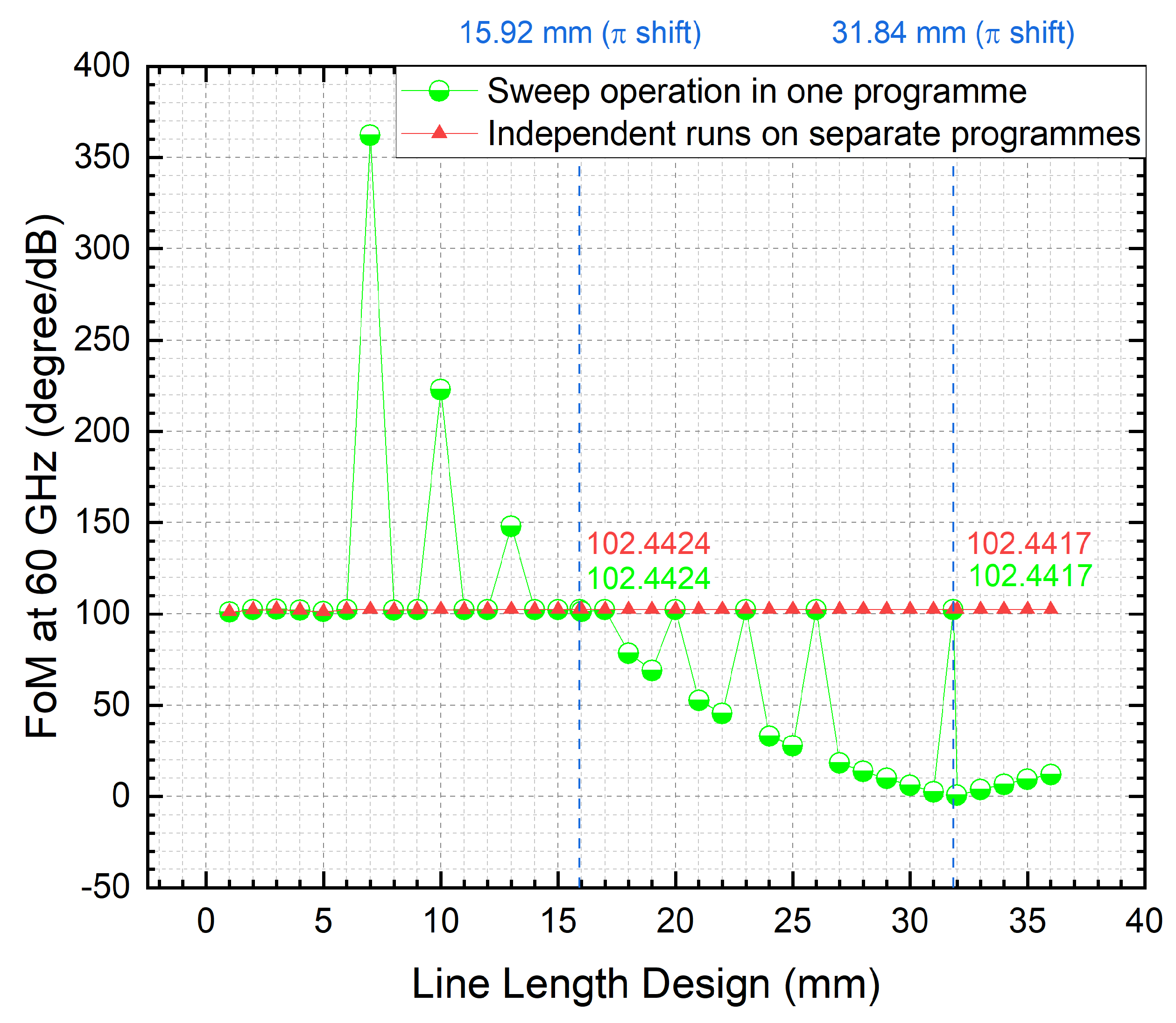
For a decently reliable simulator, the results should arguably reflect that the device is phase-shift-worthy and in good condition in theory. Figure 4 reveals that the running method of LLP in a single program fails to always meet this expectation (instead, it deviates largely and significantly, as evidenced in the fluctuating peaks), while the independent running separately in individual models always matches well with the theoretically derived DPS results (equations as per [25]). Notably, the 180° (π) shift (length of 15.92 mm) and 360° (2π) shift (length of 31.84 mm) are fortunately free of the deviating issue by the vulnerable length-sweeping method (in a single model).
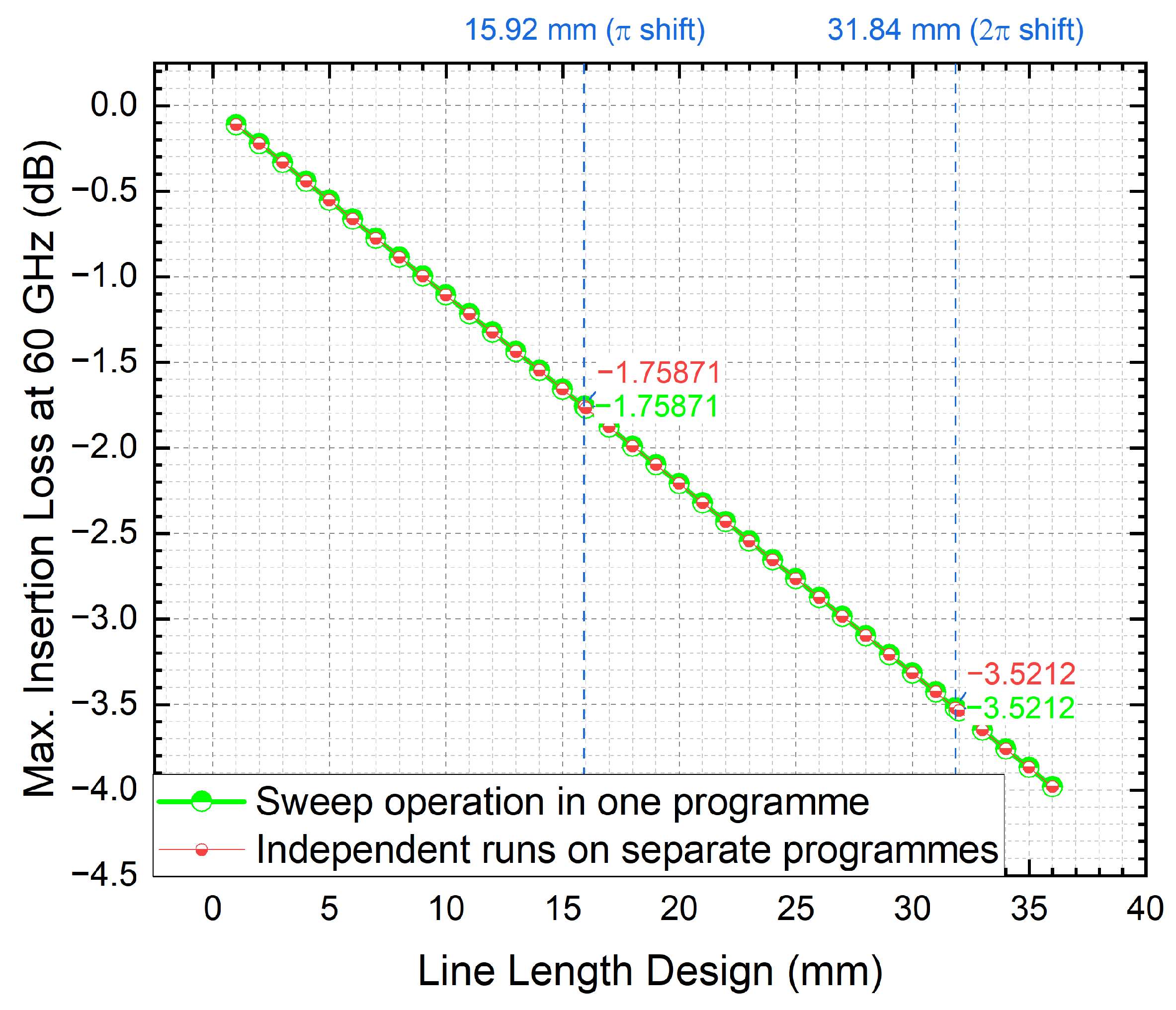
However, this does not rule out the vulnerability as indicated in the outcome (the green curve for the DPS of coaxial lines of different lengths obtained by sweeping in a single program), wherein the processed DPS results of different lengths are fluctuating but nearly symmetrical about the vertical line of 16 mm in the interval from 1 mm to 31 mm. As shown in Figure 5 regarding the division into the maximum (max.) insertion loss of LC-filled coaxial lines of various lengths simulated at 60 GHz under the optimal LC thickness (fixed), the results are identical among the two running methods, i.e., both are linearly related to the length of the coaxial line and increase with frequency. Particularly, the max. insertion loss amounts to 1.75871 dB for the 180° shifting design, and 3.5212 dB for the 360° (2π) shifting design. From the overlapped curves in Figure 5, the vulnerability does not apply to the power dissipation analysis, i.e., the computed insertion loss is insensitive to the parametric approach.
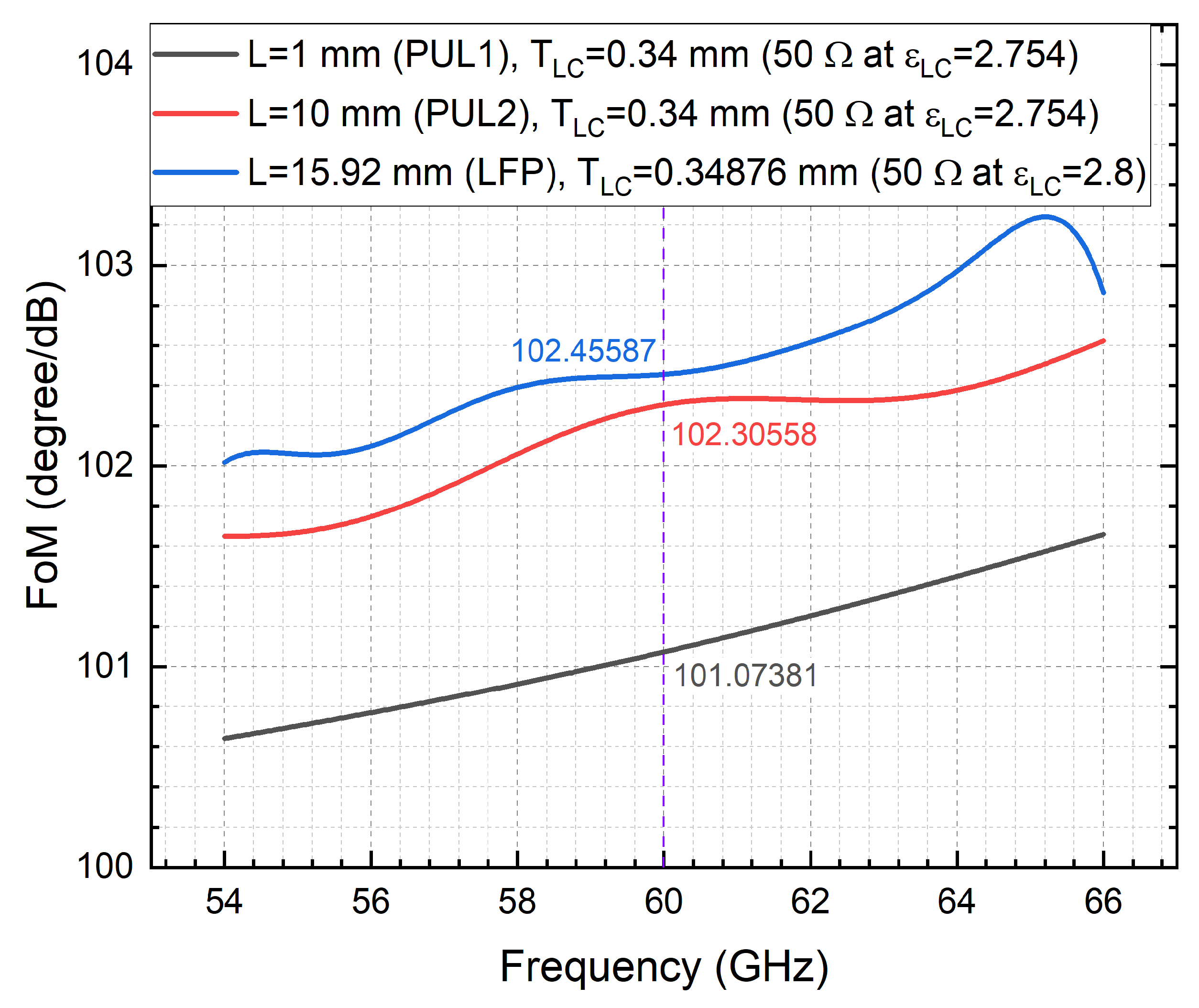
Combining the results of Figure 4 and Figure 5, the FoM are identified accordingly (as per the classically defined ratio [24,25]) and compared in Figure 6. With the length-sweeping operation is run in a single model, the comprehensive performance of phase shift-to-insertion loss is maximized when the length is 7 mm. When the length is over 17 mm, the FoM tends to decrease as the length increases. Nevertheless, the independent running approach (free of the phase shifting deviation issue as shown earlier) reports a relatively stable FoM behavior (leveling-off at 102.4°/dB) with the line length (from 1 mm to 36 mm).

2.2. Discussions and Implications

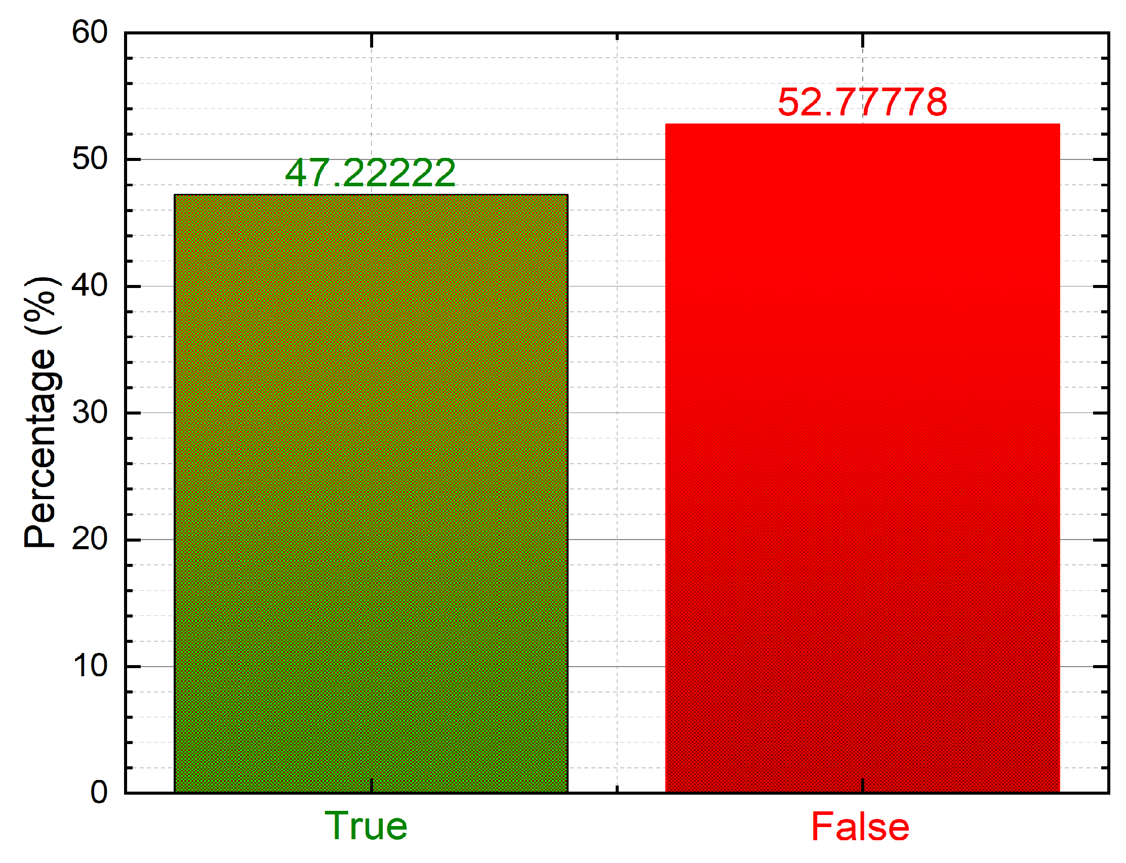
This work concerns the quantitative impact of the delay line length on FoM and the computational cost of LC-enabled continuously modifiable phase shifters at the 60 GHz band. Similarly, unreasonable simulation results (disagreeing with device physics) occur in our LC-sandwiched bandpass filter designs that are underway when scanning the coupled line lengths for predicting the corresponding S-parameters at 60 GHz. Since the optimization landscape is universally restricted by the knowledge of FoM, the single model length-sweeping operation is highly vulnerable to misleading the device design and prototype process, with an error rate surged (52.78% as quantified in Figure 7 below) for the coaxial phase shifter case.
As evidenced by the benchmark (Figure 4, Figure 5 and Figure 6), a reasonably practicable countermeasure is proposed, i.e., by implementing each line length model individually, i.e., running a host of independent models with different line lengths (accuracy of 100% demonstrated), instead of running a single parameterizing length model (accuracy of only 47.22% as per the statistics in Figure 7).
To generalize the findings of this study, we investigate the root cause of the differential phase-shifting (DPS) prediction discrepancies between the two approaches illustrated in Figure 2 for line length parameterization (LLP) simulations. The occurrence of DPS errors is attributed to the port-to-port phase calibration ambiguity in HFSS, specifically related to the definition of each port’s zero-degree phase reference. To address this ambiguity, an integration (calibration) line must be established for each port. In the single-program sweeping paradigm (Figure 2 on the left), where line length is parameterized within a single program, integration lines for mode calibration are defined for both port 1 and port 2; however, these lines are valid only for the solved center frequency and initial geometry (more specifically, valid for the port 1 that is fixed, but not for port 2 that is moving away from port 1). When the geometry varies during automatic line length sweeps (e.g., when increasing the line length from 1 mm to 36 mm, as in this study), inconsistencies in the zero-phase reference may arise (e.g., port 2 moving farther from port 1), leading to DPS errors, as shown in Figure 4. We quantify the likelihood of these errors at 52.78% for the first time (Figure 7).
In contrast, the proposed approach of running LLP in separate independent programs (Figure 2 on the right) avoids this vulnerability, as each model defines its own integration lines for both ports, thereby mitigating phase ambiguity. Interestingly, the two computational paradigms (including the vulnerable sweep-in-one-program approach) are both secure in the insertion loss prediction, as evidenced in the identical S21 (dB) results in Figure 5 among the two approaches. This is because the DPS error is only phase-related and has no relation to the power (signal amplitude). This further supports our judgment of the root cause investigation. With these in mind (i.e., the DPS errors in Figure 4 due to the phase ambiguity by the sweep-in-one-program approach, combined with the running method-insensitive insertion loss in Figure 5), the complicated patterns presented in Figure 6 for the figure-of-merit (FoM) can be reasonably deciphered with ease for the first time.

2.3. Computational Time and Memory Usage of the Vulnerability-Free Approach

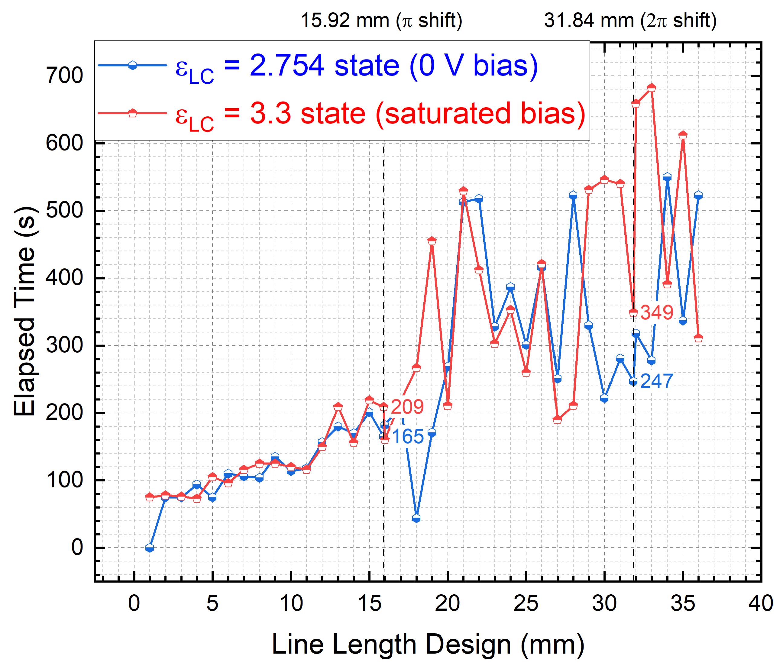
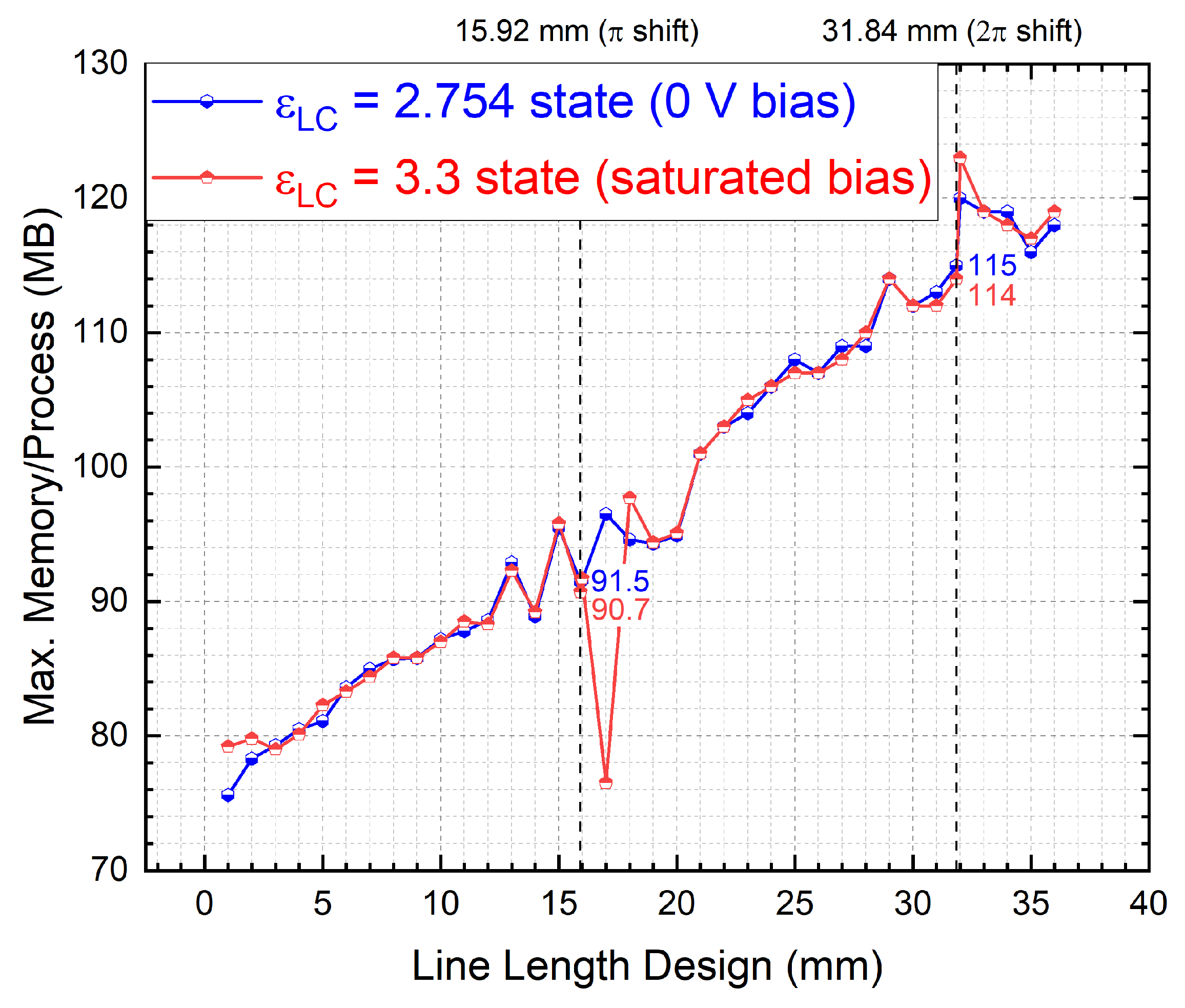
Notably, running the full-wave models for the LC-based phase shifters of a long length (e.g., targeting up to 2π of phase shift at a specific RF spectrum) demands significant computing and memory resources, hence the need for balancing the model’s effectiveness, memory usage, and computational cost. By reaching behind the scenes for running independent models with different line lengths (i.e., free of the vulnerability in Section 2.1), we identify the computation time and memory consumed (upon convergence) in Figure 8 and Figure 9, respectively, as well as the corresponding mesh elements solved in Figure 10, concerning the two extreme bias states (operational tuning range) of LC, i.e., the 0 V bias (isotropic) state with ε L C of 2.754 and the saturated bias state with ε L C of 3.3, as the key enabling property specifically for an LC-filled coaxial delay line, as we first raised in [25].
The computational costs (time and memory) rise with the increase in the line length in a largely linear manner. The two extreme tuning states of LC play a minimal role in the computational statistics of the meshing elements (as evidenced by Figure 10) and the consumed memory (deviated by less than 1 MB as evidenced by Figure 9). The convergence time of the two biasing states largely agrees with each other for the line lengths below 12 mm, beyond which the fluctuations become more pronounced. By way of illustration, the deviation rises from 44 s (the line length of 15.92 mm for π shift) to 102 s (the line length of 31.84 mm for 2π shift). More specifically, the saturated bias state (with a higher dielectric constant) constitutes the more time-consuming part.
With regard to the specific meshes (tetrahedral) implemented in the constitutive materials (dielectric volumes and conductor surfaces), LC is most computationally intensive as it occupies the most significant integral part of the volume (dielectric) with the increase in the line length, as compared with the surface integral upon the grounding surface (inner) and core line surface (outer).

3. Vulnerabilities of Mainstream Per-Unit-Length (PUL) Paradigm

The status and challenges ahead for unlocking liquid crystal (LC) reconfigurable delay line phase shifters (RDLPS) in the evolution from 5G to 6G have been concisely described and documented in [18]. Despite the vastly diverse geometries developed for RDLPS with LC, the principles of phase shifting [14,25,44] (as well as the cost function concerning the insertion loss [31]) are identical in terms of integrating the anisotropy (of various scales) over the line length of the device. As such, to facilitate iterative designs and bring device optimizations to life (theoretically or computationally) without incurring heavy computational burden (complexity and cost), the per-unit-length (PUL) framework [45,46,47,48,49] has been widely employed in microwave (and optical) transmission line studies, wherein the transferable knowledge and practice also guides quick assessment of a phase shifter device’s performance concerning the capability of the differential phase shift, the insertion loss, and hence, the FoM [24].
However, limitations of the PUL methodology have yet to be clear for LC-based RDLPS across the globe. For the first time, we observe and discuss vulnerabilities of the PUL metric by identifying a vulnerable case (Section 3.1) and proposing remediating recommendations (Section 3.2) based on S 21 quantifications of similar coaxial cross-section designs but differing in the propagating line lengths incorporated into the study.

3.1. Limitation of PUL on Predicting Insertion Loss’s Frequency Response

The first-observed vulnerability concerns the maximum insertion loss state prediction of the LC RDLPS, which is traditionally believed to occur at the 0 V bias state of LC (wherein the dielectric absorption is peaking) [27] and believed to be increasing with frequency, as depicted in the simulated 54 GHz to 66 GHz example case at Figure 11 below for evidence. The results agreeing with the rule of thumb here are based on the line length of 1 mm, i.e., the per-unit-length (PUL) paradigm for a coaxially filled LC RDLPS design with the tunable dielectric thickness of 0.41 mm (for 50 Ω impedance matching at the LC’s upper extreme biasing status of ε L C = 3.3). All the S-parameters mentioned here are renormalized to 50 Ω. The mathematics, underlying physics, as well as coaxially filled LC material’s dielectric properties, are extensively detailed in our past work [25], to which interested readers can refer for more technical background information.
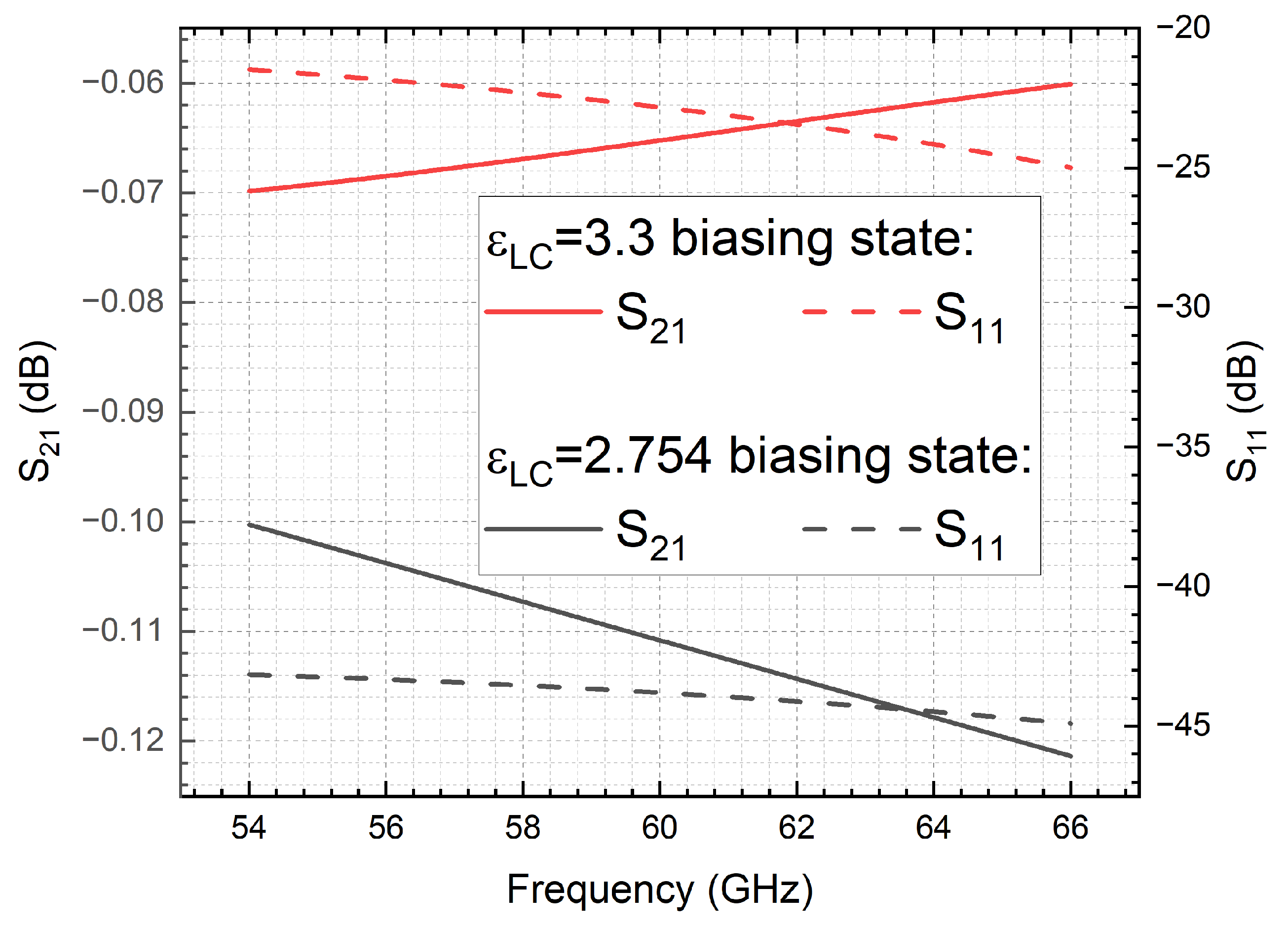
However, a design that disagrees with the aforementioned conclusions is showcased in Figure 12 below, following the same line length of 1 mm, i.e., the per-unit-length (PUL) paradigm for the same coaxially filled LC RDLPS design (identical core line diameter) but with the tunable dielectric thickness of 0.34 mm (for 50 Ω impedance matching at the LC’s lower extreme biasing status of ε L C = 2.754). Here, the insertion loss for the biased ε L C = 3.3 state is unexpectedly declining with the frequency from 54 GHz to 66 GHz, albeit the maximum insertion loss case still holds for the ε L C = 2.754 bias. The unexpected frequency reverting phenomenon is because of the unneglectable return loss (for the ε L C = 3.3 biasing state that is least matched with 50 Ω) that is reducing with the frequency, indicating an improved transmission.

3.2. Recommendations for Figure-of-Merit Prediction

As illustrated above on the line length-incurred different trends of insertion loss versus frequency for impedance matching and mismatching cases (return loss matters), it is not trivial (or even becomes a fresh engineering challenge) to compare fairly with other people’s work (on RDLPS), as people normally design, measure, and report at different lengths, different frequencies, etc. As such, it is strategically imperative to thoroughly understand the line length effect on the overall performance, i.e., figure-of-merit (FoM), for which the current studies are missing. More specifically, the accuracy (validity) of the FoM (i.e., defined as the maximum phase-shift-to-maximum-insertion-loss ratio) is directly affected by the predicted maximum insertion loss state that is not linearly varying with the frequency (whereas the differential phase shift is theoretically increasing with frequency linearly). Arguably, the effectiveness of this vulnerability due to the return loss dominance begins to fade as the level of impedance matching improves.
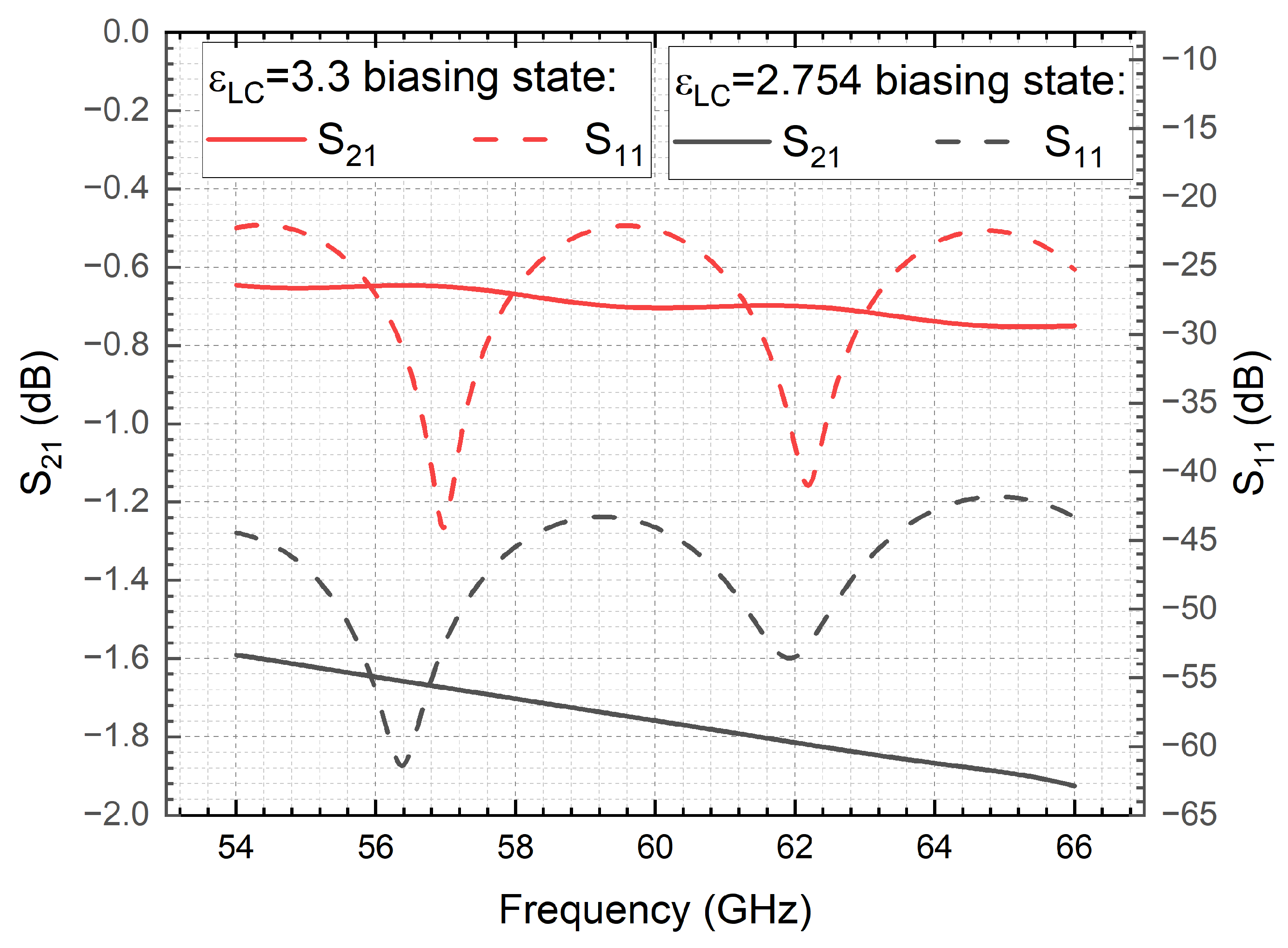
An alternative method of performance benchmarking (as recommended in this work) is obtaining the necessary line length for a fixed phase shift (e.g., π or 2π) and computing the corresponding maximum (and minimum) insertion loss. This method is useful to rule out the aforementioned deficiency (uncertainty) of the frequency reverting and FoM metrics. By way of illustration in Figure 13, a line length of 15.92 mm computed for a maximum phase-shifting range of 0 to π at 60 GHz is selected for a similar case study, with a minor perturbation on the cross-session geometry that is optimized by [25] with the tunable dielectric thickness of 0.34876 mm (for 50 Ω impedance matching at one of the LC’s intermediate biasing statuses of ε L C = 2.8), whilst keeping the same core line diameter.
Interestingly, the discrepancy can happen regarding the estimated FoM for different lengths, i.e., the FoM predicted by the PUL framework may deviate from that based on the length for π shifting (LFP paradigm). Furthermore, the FoM predicted by the 1 mm-oriented PUL framework (e.g., denoted as PUL1) can deviate from that by the 10 mm (1 cm)-oriented PUL2 approach, as depicted in Figure 14. These deviations report up to 1.38206°/dB at 60 GHz, i.e., the L = 1 mm (PUL1) underestimates the FoM performance by 1.38206°/dB as compared with the proposed LFP framework.
In this context, care must be taken on the usage of PUL in predicting the FoM for various lengths, wherein the PUL approach virtually fails to convey the big picture of the device operation. For FoM comparison purposes, among different geometry designs and diverse technologies, the PUL-based results may deviate from the more practical LFP paradigm, i.e., the line length effect tips the balance in decision-making.
Arguably, the PUL approach is unresponsive for the return loss characterization and hence cannot be a substitute for full-length-based performance prediction. Instead of using the common PUL metric, deploying the uniquely diverse approach based on the length-for-π (LFP) framework specifically catered toward the industry-standard phase shifter component design can remediate the susceptibilities raised above, and hence deliver real-world impact.

4. Conclusions and Future Research Outlook

In conclusion, the emerging perspectives derived in this work alert the relevant researchers and academics to familiarize themselves with the HFSS’s deficiency of the differential phase shift (DPS) parameterized with the line length, so that they do not inadvertently obtain unreasonable results, more specifically, encompassing the DPS and figure-of-merit (FoM) for decision-making. Both foundational science (device physics) and engineering (computational) implications (parallel computing and execution time) are delivered, unveiling the hidden truths of line-length-dependent FoM vulnerability. Despite HFSS’s prevalence in the full-wave simulation market and the significant advantages acknowledged around the globe, so far, the newly raised line-length varying-induced matter spotted in this work demonstrates that the embedded single parametric model has not been able to reliably and stably predict the DPS of the LC-based reconfigurable phase shifters at mmW frequencies due to the phase ambiguity concern identified and the error rate quantified in this work.
Besides the remediation strategy of running individual models (least-risky pathway, albeit time-consuming and human-invention intensive), a sub-routine in line length sweeping with the phase calibration automatically adjusted for digital twinning is highly suggested to be developed for agile reconfigurable applications (e.g., variable phase shifters and tunable filters), catering to addressing the DPS prediction instability issue (for phase shifters); band rejection misjudgment (for filters) occurred at the automatic line length scanning operation of the closed-source simulator, the early diagnostic of which dramatically mitigates the follow-up re-investigation time and associated costs for revisiting the problem. Rather, the technical implications derived in this work enable practitioners to design LC phase shifters unaided (hassle-free) for the first time, toward a loftier goal of formulating an open-sourced tool to navigate the complex instabilities in DPS estimations for maintaining a standardized definition of FoM. Last but not least, while the use of FoM accelerates the decision-making process, it is a one-dimensional index that compromises the multi-modality representation, e.g., phase shift, insertion loss, return loss, weight, tuning speed, tuning power consumption, footprint, cost, fabrication time, etc. In the decision-making phase, the device designers and engineers are still key. Fundamentally, researchers always intend to understand as well as predict the device.
In addition, the previously unthinkable value of data and rigorousness of information regarding the insertion loss per unit length (PUL) and the accordingly derived FoM need a re-evaluation to inform more accurate decision-making, for example, when conducting a comparative study into different solutions or geometries of liquid crystal (LC) reconfigurable delay line phase shifters (RDLPS) for feeding phased array antennas that underpin the next-generation wireless communications, detections, sensing, navigation, etc. In this paper, we raised this issue and identified clues about particularly vulnerable insertion loss misjudgment cases due to the use of the conventional PUL paradigm that is likely to lead to misleading decision-making and easily be overlooked. The chief challenges inherent in simply using the PUL method to reflect on the insertion loss performance are owing to the non-linear dependency of the return loss on the line length. Remediation strategies are proposed based on a tailored scenario-based approach, i.e., assessing the insertion loss performance by either restricting the same-length comparison or by the length-for-π framework, the insight of which broadens the horizons of LC-based RDLPS technology, as diverse voices in the use of the mainstream PUL framework are first registered and engaged into the discussion of the standardized performance comparison metric.
Ongoing research is delving into the results in Figure 14 with more quantitative detail, i.e., investigating and confirming whether the FoM is monotonously increasing (or insensitive) with the delay line length. Answering this question will further extend the boundary of knowledge in LC-based RDLPS concerning the optimization dimension beyond the classic cross-sectional polarization (mode) dependency. A pivotal element entails the utilization of simulations to augment the formulation of experimental designs and facilitate the elucidation of experimental outcomes. Simulation data are the main outputs of the study, which is quite reasonable given the nature of the research, yet the application of experimental data would strengthen the given findings as to the existence of the problems and the efficiency of the proposed solutions. Another scope of our future development is expanding the current PUL implications drawn from the 60 GHz millimeter-wave (V band) regime to the optical wavelength ranges and benchmark with state-of-the-art LC-enabled optical waveguide delay line phase shifters, e.g., examining the work from [50] that relies on the classical PUL relation and hence deriving the frequency applicability of the PUL vulnerabilities spotted in the current work.

Author Contributions

Conceptualization and methodology, J.L.; software, H.L. and J.L.; validation and formal analysis, J.L. and H.L.; investigation and data curation, J.L. and H.L.; writing—original draft preparation, J.L. and H.L.; writing—review and editing, J.L.; visualization, J.L. and H.L.; supervision, J.L.; project administration and funding acquisition, J.L. All authors have read and agreed to the published version of the manuscript.

Funding

This research is funded in part by the National Natural Science Foundation of China, grant number 62301043.

Data Availability Statement

The data presented in this study are available on request from the corresponding author.

Conflicts of Interest

The authors declare no conflicts of interest. The funders had no role in the design of the study; in the collection, analyses, or interpretation of data; in the writing of the manuscript; or in the decision to publish the results.

Abbreviations

The nomenclatures and their abbreviations that appeared in this work are provided below.
NomenclaturesAbbreviations
Differential phase shiftDPS
Inverted microstrip lineIMS
Reconfigurable delay line phase shifterRDLPS
Figure-of-meritFoM
Liquid crystalLC
Liquid crystal displayLCD
Coplanar waveguideCPW
Shielded coplanar waveguideSCPW
Line length parameterizationLLP
Radio frequencyRF
Microwave-waveMW
Millimeter-wavemmW
MegabyteMB
GigahertzGHz
TerahertzTHz
Transverse electromagneticTEM
Scattering parametersS parameters
Forward transmission coefficientS21
Forward reflection coefficientS11
Effective permittivityeff
Three dimensional3D
Fifth-generation wireless5G
Sixth-generation wireless6G
High-frequency structure simulatorHFSS
Per-unit-lengthPUL

References

  1. White, J.F. Review of semiconductor microwave phase shifters. Proc. IEEE 1968, 56, 1924–1931. [Google Scholar] [CrossRef]
  2. Nagra, A.S.; York, R.A. Distributed analog phase shifters with low insertion loss. IEEE Trans. Microw. Theory Tech. 1999, 47, 1705–1711. [Google Scholar] [CrossRef]
  3. Iseghem, L.V.; Picavet, E.; Takabayashi, A.Y.; Edinger, P.; Khan, U.; Verheyen, P.; Quack, N.; Gylfason, K.B.; Buysser, K.D.; Beeckman, J. Low power optical phase shifter using liquid crystal actuation on a silicon photonics platform. Opt. Mater. Express 2022, 12, 2181–2198. [Google Scholar] [CrossRef]
  4. Anjos, E.V.P.; Schreurs, D.M.M.P.; Vandenbosch, G.A.E.; Geurts, M. A 14–50-GHz Phase Shifter with All-Pass Networks for 5G Mobile Applications. IEEE Trans. Microw. Theory Tech. 2020, 68, 762–774. [Google Scholar] [CrossRef]
  5. Grottke, T.; Hartmann, W.; Schuck, C.; Pernice, W.H. Optoelectromechanical phase shifter with low insertion loss and a 13π tuning range. Opt. Express 2021, 29, 5525–5537. [Google Scholar] [CrossRef]
  6. Stark, L. Microwave theory of phased-array antennas—A review. Proc. IEEE 1974, 62, 1661–1701. [Google Scholar] [CrossRef]
  7. Rao, J.B.L.; Patel, D.P.; Sengupta, L.C. Phased array antennas based on bulk phase shifting with ferroelectrics. Integr. Ferroelectr. 1998, 22, 307–316. [Google Scholar] [CrossRef]
  8. Scardelletti, M.C.; Ponchak, G.E.; Zaman, A.J.; Lee, R.Q. RF MEMS phase shifters and their application in phase array antennas. In Proceedings of the 2005 IEEE Annual Conference Wireless and Micrwave Technology, Clearwater Beach, FL, USA, 6–7 April 2005; pp. 191–194. [Google Scholar]
  9. Adomnitei, C.I.; Lesanu, C.E.; Done, A.; Yu, A.; Dimian, M.; Lavric, A. The Design and Implementation of a Phased Antenna Array System for LEO Satellite Communications. Sensors 2024, 24, 1915. [Google Scholar] [CrossRef]
  10. Abdalmalak, K.A.; Santamaría Botello, G.; Llorente-Romano, S.; Rivera-Lavado, A.; Flygare, J.; López Fernándezs, J.A.; Serna Puente, J.M.; García-Castillo, L.E.; Segovia-Vargas, D.; Pantaleev, M.; et al. Ultrawideband Conical Log-Spiral Circularly Polarized Feed for Radio Astronomy. IEEE Trans. Antennas Propag. 2020, 68, 1995–2007. [Google Scholar] [CrossRef]
  11. Rocca, P.; Mailloux, R.J.; Herd, J.S.; Massa, A. Recent Trends on Unconventional Phased Array Architectures for Communication, Sensing and Wireless Power Transmission. In Proceedings of the 2022 IEEE International Symposium on Antennas and Propagation and USNC-URSI Radio Science Meeting (AP-S/URSI), Denver, CO, USA, 10–15 July 2022; pp. 1610–1611. [Google Scholar]
  12. Eid, A.; Hester, J.G.D.; Tentzeris, M.M. 5G as a wireless power grid. Sci. Rep. 2021, 11, 636. [Google Scholar] [CrossRef]
  13. Kawamoto, H. The history of liquid-crystal display and its industry. In Proceedings of the 2012 Third IEEE History of Electro-Technology Conference (HISTELCON), Pavia, Italy, 5–7 September 2012; pp. 1–6. [Google Scholar]
  14. Weil, C.; Luessem, G.; Jakoby, R. Tunable inverted-microstrip phase shifter device using nematic liquid crystals. In Proceedings of the 2002 IEEE MTT-S International Microwave Symposium Digest, Seattle, WA, USA, 2–7 June 2002; pp. 367–371. [Google Scholar]
  15. Kuki, T.; Fujikake, H.; Nomoto, T. Microwave variable delay line using dual-frequency switching-mode liquid crystal. IEEE Trans. Microw. Theory Tech. 2002, 50, 2604–2609. [Google Scholar] [CrossRef]
  16. Muller, S.; Scheele, P.; Weil, C.; Wittek, M.; Hock, C.; Jakoby, R. Tunable passive phase shifter for microwave applications using highly anisotropic liquid crystals. In Proceedings of the 2004 IEEE MTT-S International Microwave Symposium Digest, Fort Worth, TX, USA, 6–11 June 2004; pp. 1153–1156. [Google Scholar]
  17. Yaghmaee, P.; Karabey, O.H.; Bates, B.; Fumeaux, C.; Jakoby, R. Electrically Tuned Microwave Devices Using Liquid Crystal Technology. Int. J. Antennas Propag. 2013, 2013, 824214. [Google Scholar] [CrossRef]
  18. Li, J. Challenges and Opportunities for Nematic Liquid Crystals in Radio Frequency and Beyond. Crystals 2022, 12, 632. [Google Scholar] [CrossRef]
  19. Quintana, D.P.; Aguirre, E.; Olariaga, E.; Kuznetsov, S.A.; Lapanik, V.I.; Sutormin, V.S.; Zyryanov, V.Y.; Marcotegui, J.A.; Beruete, M. Reconfigurable Millimeter-Wave Reflectarray Based on Low-Loss Liquid Crystals. IEEE Trans. Antennas Propag. 2024, 72, 531–541. [Google Scholar] [CrossRef]
  20. Oikonomou, V.K. Engineering and Materials: Editorial. Symmetry 2023, 15, 1902. [Google Scholar] [CrossRef]
  21. Ishihara, S.; Uto, S. Symmetry and Liquid Crystals. Symmetry 2023, 15, 691. [Google Scholar] [CrossRef]
  22. Koul, S.K.; Dey, S.; Poddar, A.K.; Rohde, U.L. Ka-band reliable and compact 3-bit true-time-delay phase shifter using MEMS single-pole-eight-throw switching networks. J. Micromech. Microeng. 2016, 26, 104002. [Google Scholar] [CrossRef]
  23. Neuder, R.; Späth, M.; Schüßler, M.; Sáez, A.J. Architecture for sub-100 ms liquid crystal reconfigurable intelligent surface based on defected delay lines. Commun. Eng. 2024, 3, 70. [Google Scholar] [CrossRef]
  24. Jakoby, R.; Gaebler, A.; Weickhmann, C. Microwave Liquid Crystal Enabling Technology for Electronically Steerable Antennas in SATCOM and 5G Millimeter-Wave Systems. Crystals 2020, 10, 514. [Google Scholar] [CrossRef]
  25. Li, J.; Li, H. Liquid Crystal-Filled 60 GHz Coaxially Structured Phase Shifter Design and Simulation with Enhanced Figure of Merit by Novel Permittivity-Dependent Impedance Matching. Electronics 2024, 13, 626. [Google Scholar] [CrossRef]
  26. Sahbani, F.; Hrizi, H.; Tentillier, N.; Gharsallah, A.; Legrand, C. High Birefringence Liquid Crystal for Tunable Microwave Phase Shifter: Design, Characterization and Performance Analysis. In Proceedings of the 2023 22nd Mediterranean Microwave Symposium (MMS), Sousse, Tunisia, 30 October–1 November 2023; pp. 1–4. [Google Scholar]
  27. Zografopoulos, D.C.; Ferraro, A.; Beccherelli, R. Liquid-crystal high-frequency microwave technology: Materials and Characterization. Adv. Mater. Technol. 2018, 4, 1800447. [Google Scholar] [CrossRef]
  28. Koperwas, K.; Adrjanowicz, K.; Grzybowski, A.; Paluch, M. The role of the dipole moment orientations in the crystallization tendency of the van der Waals liquids—Molecular dynamics simulations. Sci. Rep. 2020, 10, 283. [Google Scholar] [CrossRef] [PubMed]
  29. Li, J.; Li, H. Effective Dielectric Constant Benchmark of 60 GHz Liquid Crystal-Filled Coaxial Delay Line. In Proceedings of the 2024 IEEE International Conference on Computational Electromagnetics (ICCEM), Nanjing, China, 15–17 April 2024; pp. 1–3. [Google Scholar]
  30. White, J.F. Diode Phase Shifters for Array Antennas. IEEE Trans. Microw. Theory Techn 1974, 22, 658–674. [Google Scholar] [CrossRef]
  31. Li, J. Rethinking Liquid Crystal Tunable Phase Shifter Design with Inverted Microstrip Lines at 1–67 GHz by Dissipative Loss Analysis. Electronics 2023, 12, 421. [Google Scholar] [CrossRef]
  32. Massoni, E.; Bozzi, M.; Perregrini, L.; Tamburini, U.A.; Tomassoni, C. A novel class of high dielectric resonator filters in microstrip line technology. In Proceedings of the 2017 IEEE MTT-S International Microwave Workshop Series on Advanced Materials and Processes for RF and THz Applications (IMWS-AMP), Pavia, Italy, 20–22 September 2017; pp. 1–3. [Google Scholar]
  33. Abdulkarim, Y.I.; Deng, L.; Karaaslan, M.; Altıntaş, O.; Awl, H.N.; Muhammadsharif, F.F.; Liao, C.; Unal, E.; Luo, H. Novel Metamaterials-Based Hypersensitized Liquid Sensor Integrating Omega-Shaped Resonator with Microstrip Transmission Line. Sensors 2020, 20, 943. [Google Scholar] [CrossRef]
  34. Li, J.; Chu, D. Liquid Crystal-Based Enclosed Coplanar Waveguide Phase Shifter for 54–66 GHz Applications. Crystals 2019, 9, 650. [Google Scholar] [CrossRef]
  35. Li, J.; Xu, H.; Chu, D. Design of liquid crystal based coplanar waveguide tunable phase shifter with no floating electrodes for 60–90 GHz applications. In Proceedings of the 2016 46th European Microwave Conference (EuMC), London, UK, 4–6 October 2016; pp. 1047–1050. [Google Scholar]
  36. Nose, T.; Chien, L.C.; Catanescu, O.; Golvin, A.; Ito, Y.; Sasamori, T.; Isota, Y.; Ito, R.; Honma, M. Improved High-Frequency Performance of Microstrip-Line-Type Liquid Crystal Phase Shifter. Jpn. J. Appl. Phys. 2013, 52, 091701. [Google Scholar] [CrossRef]
  37. Neuder, R.; Wang, D.; Schüßler, M.; Jakoby, R.; Sáez, A.J. Compact Liquid Crystal-based Defective Ground Structure Phase Shifter for Reconfigurable Intelligent Surfaces. In Proceedings of the 2023 17th European Conference on Antennas and Propagation (EuCAP), Florence, Italy, 26–31 March 2023; pp. 1–5. [Google Scholar]
  38. Garbovskiy, Y.; Zagorodnii, V.; Krivosik, P.; Lovejoy, J.; Camley, R.E.; Celinski1, Z.; Glushchenko, A.; Dziaduszek, J.; Dąbrowski, R. Liquid crystal phase shifters at millimetre wave frequencies. J. Appl. Phys. 2012, 111, 054504. [Google Scholar] [CrossRef]
  39. Bilotti, F.; Barbuto, M.; Zarghani, Z.H.; Karamirad, M.; Longhi, M.; Monti, A.; Ramaccia, D.; Stefanini, L.; Toscano, A.; Vellucci, S. Reconfigurable intelligent surfaces as the key-enabling technology for smart electromagnetic environments. Adv. Phys. X 2024, 9, 2299543. [Google Scholar] [CrossRef]
  40. Anand, P.; Sharma, S.; Sood, D.; Tripathi, C.C. Design of compact reconfigurable switched line microstrip phase shifters for phased array antenna. In Proceedings of the 2012 1st International Conference on Emerging Technology Trends in Electronics, Communication & Networking, Surat, India, 19–21 December 2012; pp. 1–3. [Google Scholar]
  41. Antony, A.J.; Sudesh, A.A.; Mohamed, A.; Gopika, R.; Mitra, A.; Sarkar, D.; Saha, C. Design of a 360° Continuously Variable Phase Shifter using Improved Regression Algorithm for X-band Phased Array Applications. In Proceedings of the 2021 IEEE MTT-S International Microwave and RF Conference (IMARC), Kanpur, India, 17–19 December 2021; pp. 1–4. [Google Scholar]
  42. Zhang, X.; Daryoush, A.S. Full 360 degrees phase shifting of injection-locked oscillators. IEEE Microw. Wirel. Compon. Lett. 1993, 3, 14–16. [Google Scholar] [CrossRef]
  43. Li, J.; Li, H. Symmetry Implications of a 60 GHz Inverted Microstrip Line Phase Shifter with Nematic Liquid Crystals in Diverse Packaging Boundary Conditions. Symmetry 2024, 16, 798. [Google Scholar] [CrossRef]
  44. Lim, K.C.; Margerum, J.D.; Lackner, A.M. Liquid crystal millimeter wave electronic phase shifter. Appl. Phys. Lett. 1993, 62, 1065–1067. [Google Scholar] [CrossRef]
  45. Inan, A.S.; Osterberg, P.M. Calculating the per-unit-length circuit parameters of a coaxial transmission line using singularity functions. In Proceedings of the IEEE Antennas and Propagation Society Symposium, Monterey, CA, USA, 20–25 June 2004; pp. 2067–2070. [Google Scholar]
  46. Südekum, S.; Leone, M. Improved Per-Unit-Length Parameter Definition for Non-Uniform and Lossy Multiconductor Transmission Lines. In Proceedings of the 2018 International Symposium on Electromagnetic Compatibility (EMC EUROPE), Amsterdam, The Netherlands, 27–30 August 2018; pp. 1–6. [Google Scholar]
  47. Matsuki, M.; Matsushima, A. Efficient numerical method for computing per-unit-length impedance of transmission lines with lossy substrate. In Proceedings of the 2012 International Symposium on Antennas and Propagation (ISAP), Nagoya, Japan, 29 October–2 November 2012; pp. 963–966. [Google Scholar]
  48. Azadeh, S.S.; Merget, F.; García, S.R.; Mártir, A.M.; Driesch, N.V.D.; Müller, J.; Mantl, S.; Buca, D.; Witzens, J. Low Vπ Silicon photonics modulators with highly linear epitaxially grown phase shifters. Opt. Express 2015, 23, 23526–23550. [Google Scholar] [CrossRef] [PubMed]
  49. Maksimov, A.E.; Kuksenko, S.P. On the Features of Calculating per-Unit-Length Parameters and Characteristics of Multiconductor Transmission Lines. J. Commun. Technol. Electron. 2023, 68, 1412–1429. [Google Scholar] [CrossRef]
  50. Alam, B.; Cornaggia, F.; Alessandro, A.; Asquini, R. Design and analysis of high performance phase shifters on polymeric slot waveguides within liquid crystal cladding. Opt. Quant. Electron. 2022, 54, 800. [Google Scholar] [CrossRef]
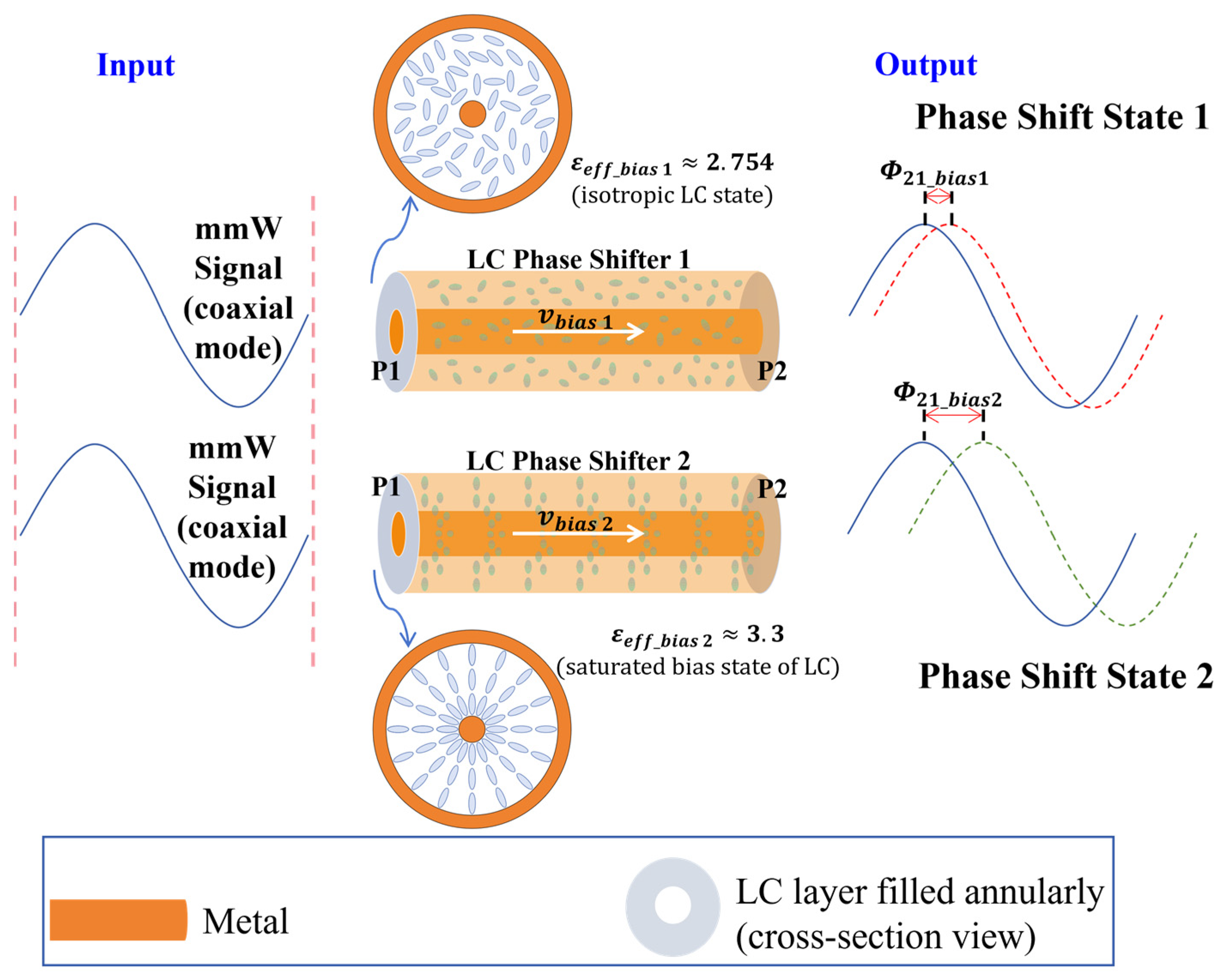
Figure 1. Illustration of the LC-enabled mmW phase-modulating mechanism via a coaxial delay line filled with tunable dielectrics (i.e., LC) from the isotropic state (0 V bias) to fully-aligned state (saturated bias), leading to the effective permittivity (eff) variation in line with the LC dielectric constant variation as derived by [25,29] for the mmW signal fully-occupied in the single-dielectric coaxial transmission line system.
Symmetry 16 01261 g001
Figure 2. Illustrations of two distinct operation routines of running LLP (lengths varying from design 1 to design N) for LC-filled coaxial delay line’s differential phase shift prediction at 60 GHz.
Symmetry 16 01261 g002
Figure 3. Photograph of our fabricated and assembled 60 GHz LC-filled phase shifters designed in two lengths for 0 to 180° (π) shifting and 0 to 360° (2π) shifting functionalities, respectively.
Symmetry 16 01261 g003
Figure 4. DPS of coaxial lines of different lengths working at 60 GHz under the optimal cross-section size (fixed LC thickness T L C = 0.34876 mm). Length-varying-induced DPS evolution is compared among two computational operating approaches and benchmarked with theory [25].
Symmetry 16 01261 g004
Figure 5. Maximum insertion loss of LC-filled coaxial delay lines of various lengths at 60 GHz under an optimal cross-section dimension (fixed LC thickness T L C = 0.34876 mm).
Symmetry 16 01261 g005
Figure 6. The 60 GHz FoM vs. line length of LC-filled coaxial phase shifter based on line length scanning run in the same model vs. run in separate models.
Symmetry 16 01261 g006
Figure 7. Accuracy statistics of DPS (and FoM) by line length scanning (from 1 mm to 36 mm) run in a single HFSS parametric model of LC-filled coaxial phase shifter at 60 GHz.
Symmetry 16 01261 g007
Figure 8. Elapsed time (in seconds) upon convergence for LC-filled coaxial delay lines of various lengths (from 1 mm to 36 mm) at 60 GHz under an optimal cross-section dimension (fixed LC thickness T L C = 0.34876 mm) and subject to two extreme biasing states of LC.
Symmetry 16 01261 g008
Figure 9. Memory consumed (in MB) upon convergence for LC-filled coaxial delay lines of various lengths (from 1 mm to 36 mm) at 60 GHz under an optimal cross-section dimension (fixed LC thickness T L C = 0.34876 mm) and subject to two extreme biasing states of LC.
Symmetry 16 01261 g009
Figure 10. The number of meshed elements solved upon convergence for LC-filled coaxial delay lines of various lengths (from 1 mm to 36 mm) at 60 GHz under an optimal cross-section dimension (fixed LC thickness T L C = 0.34876 mm) and subject to two extreme biasing states of LC.
Symmetry 16 01261 g010
Figure 11. L = 1 mm: forward transmission ( S 21 ) and forward reflection ( S 11 ) coefficients for the coaxially tunable dielectric thickness of 0.41 mm design (50 Ω matched at ε L C = 3.3). Simulated results were renormalized to 50 Ω and recorded for two extreme biasing states of LC.
Symmetry 16 01261 g011
Figure 12. L = 1 mm: forward transmission ( S 21 ) and forward reflection ( S 11 ) coefficients for the coaxially tunable dielectric thickness of 0.34 mm design (50 Ω matched at ε L C = 2.754). Simulated results were renormalized to 50 Ω and recorded for two extreme biasing states of LC.
Symmetry 16 01261 g012
Figure 13. L = 15.92 mm for π shifting: forward transmission ( S 21 ) and forward reflection ( S 11 ) coefficients for the coaxially tunable dielectric thickness of T L C = 0.34876 mm (50 Ω matched at ε L C = 2.8). Simulated results were renormalized to 50 Ω and recorded for two extreme biasing states of LC.
Symmetry 16 01261 g013
Figure 14. Frequency response of FoM for three designs of a similar cross-section geometry but differing in line lengths: L = 1 mm (per-unit-length framework 1), 10 mm (per-unit-length framework 2), and 15.92 mm (length for π shifting).
Symmetry 16 01261 g014
Disclaimer/Publisher’s Note: The statements, opinions and data contained in all publications are solely those of the individual author(s) and contributor(s) and not of MDPI and/or the editor(s). MDPI and/or the editor(s) disclaim responsibility for any injury to people or property resulting from any ideas, methods, instructions or products referred to in the content.