Article

Spin Wave Chiral Scattering by Skyrmion Lattice in Ferromagnetic Nanotubes

1
Department of Physics, Shanghai University, Shanghai 200444, China
2
Department of Mathematics, Shanghai University, Shanghai 200444, China
*
Author to whom correspondence should be addressed.
Symmetry 2024, 16(10), 1336; https://doi.org/10.3390/sym16101336
Submission received: 2 July 2024 / Revised: 15 September 2024 / Accepted: 8 October 2024 / Published: 10 October 2024
(This article belongs to the Special Issue Spin Chirality and Molecular Magnetism)

Abstract

:
Previous studies have demonstrated that the surface curvature of cylindrical magnetic nonawires can induce fascinating dynamic magnetization properties. It was recently proposed that ferromagnetic nanotubes can be utilized as skyrmion guides, enabling the avoidance of the annihilation of skyrmions in the lateral boundaries as in flat thin-film strips. In this work, we demonstrate via micromagnetic simulation that multiple skyrmions can be stabilized in a cross-section of a ferromagnetic nanotube with interfacial Dzyaloshinskii–Moriya interaction (iDMI). When uniformly arranged, these skyrmions together can perform as a crystal lattice for spin waves (SWs) propagating in the nanotube. Our simulations show that the skyrmion lattice can contribute a chiral effect to the SW passing through, namely a circular polarization of the SW. The handedness of the polarization is found to be determined by the polarity of the skyrmions. A physical explanation of the observed effect is provided based on the exchange of angular momentum between SWs and skyrmions during the scattering process. Our results display more possibilities to exploit magnetic nanotubes as SW and skyrmion guide in the development of novel spintronic devices.

1. Introduction

Magnetic skyrmions have been intensively studied since the first experimental observation over a decade ago [1,2,3,4,5]. In addition to fundamental interests, magnetic skyrmions are considered as a promising candidate for information carriers in future spintronic devices, such as a skyrmion racetrack memory [6]. It is basically a magnetic quasiparticle that tolerates room temperature with an nm size, topologically protected stability and much lower threshold current density compared to magnetic domain walls [7,8,9,10]. The formation of magnetic skyrmions usually requires the lack of reversal symmetry of the system, for instance, the presence of the asymmetric exchange interaction, i.e., the Dzyaloshinskii–Moriya interaction (DMI) [11,12,13]. Previous studies have mostly focused on the creation, stabilization and dynamics of skyrmions in magnetic thin films [14]. However, skyrmion motion in flat strips, usually driven by a spin-polarized current, suffers from a characteristic effect, namely, the skyrmion Hall effect [15,16,17,18]. Due to a Magnus force exerted on the skyrmion, it acquires a transverse component of velocity during its motion, which leads to the annihilation at the lateral boundaries of the strip [19,20,21]. It has been recently proposed that ferromagnetic nanotubes can be exploited as skyrmion guides [22,23,24], which feature a spiraling motion of the skyrmion around the tube. Consequently, the annihilation is avoided radically.
Owing to its topological nature, it is also interesting to study the response of skyrmions to other stimulations, such as spin waves (SWs) [25]. Due to the absence of Joule heat, SWs are considered as candidates for ultra-low power consumption information carriers [26,27,28,29,30]. It has been reported that in magnetic thin films, propagating SWs can interact with skyrmions in the system [31,32,33]. On the one hand, the skyrmion is driven to move by the SW. On the other hand, the wave vector of the SW is altered after a skew scattering caused by the skyrmion [34,35,36]. This process is attributed to the exchange of linear momentum between the SW and skyrmion [34,35]. In this paper, we study the influence of skyrmion lattice formed in ferromagnetic nanotubes on SWs propagating through. The previous studies have revealed several chiral effects of SW dynamics in cylindrical nanowires, such as the SW non-reciprocity [37,38] and the relevant so-called magnonic activity [39,40]. Our simulations show that the presence of skyrmions in nanotubes can significantly modify the profile of SW modes passing through. Specifically, a normal planar SW mode becomes circularly polarized after transmission with the handedness determined by the polarity of the skyrmions. We argue that this effect is attributed to the exchange of angular momentum between SWs and skyrmions in a tubular geometry. Our results provide possibilities for the manipulations of SW properties by using spin textures containing multiple magnetic skyrmions.

2. Materials and Methods

In micromagnetism, the magnetization dynamics of ferromagnetic nanostructures are described by the Landau–Lifshitz–Gilbert (LLG) equation, which is given by
d M d t = γ H eff × M + α M s [ M × d M d t ] ,
where M is the local magnetization, M s = M is the saturation magnetization, γ is the gyromagnetic ratio, α is the Gilbert damping parameter, and H e f f is the effective field, which usually takes into account the exchange interaction, dipolar interaction, external field and magneto-crystalline anisotropy. In our case, an interfacial Dzyaloshinskii–Moriya interaction (iDMI) is also assumed to be present in the studied system, which is taken into account in H e f f . The DMI, which is an asymmetric exchange interaction [11,12], is essential for the formation of skyrmions in the magnetic system. An electric current applied to the sample can influence the magnetization dynamics via the so-called spin-transfer torque (STT) [41,42], which has been incorporated into the extended LLG equation [43,44].
We perform micromagnetic simulations by numerically solving the LLG equation using the MuMax3 package [45]. Our studied sample is a 1000 nm cylindrical hollow wire with various inner and outer radii, which is discretized into 1 nm × 1 nm × 1 nm cubic cells in simulations. The material is assumed to be a rolled Co/Pt multilayer film with parameters as [24,46,47]: saturation magnetization M s = 580   k A / m , exchange stiffness A e x = 15   P J / m , easy–normal anisotropy K u = 800   k J / m 3 , and iDMI constant D = 1.9   m J / m 2 . The simulations were performed at zero temperature.

3. Results

Due to the anisotropy, the nanotube in equilibrium is magnetized in the radial direction either pointing outward or inward [48]. In simulations, one can artificially create a skyrmion by setting up a small region in the tube with opposite magnetization and letting the system relax. In our study, we position multiple skyrmions in one cross-section of the tube. As shown in Figure 1, four skyrmions are formed simultaneously, which are located symmetrically in a cross-section of a 25 nm outer radius tube. Without external stimulus, a stable coexistence of four skyrmions is acquired in this case. Further studies show that other numbers of skyrmions can also be arranged in one cross-section of the tube with various radii. For instance, a stable state of six skyrmions can be obtained in a 40 nm radius tube.
Before we study the influence of the skyrmion lattice on propagating SWs, we show that those multiple skyrmions can have a synchronous motion when driven by an electric current. The current-driven dynamics of a single skyrmion in nanotubes have been studied previously [22,23,24], featuring a spiraling motion of the skyrmion around the axis of the tube. Figure 2 shows the trajectory of two skyrmions formed in a cross-section driven by an electric current. Clearly, the skyrmion motion is not affected by the existence of its partner, still following a spiraling trace. The translational and rotational speeds of the two skyrmions are found to be exactly the same, making the relative position of the two skyrmions unchanged at any moment during the motion. Such a collective and synchronous motion is also observed for other amounts of skyrmions.
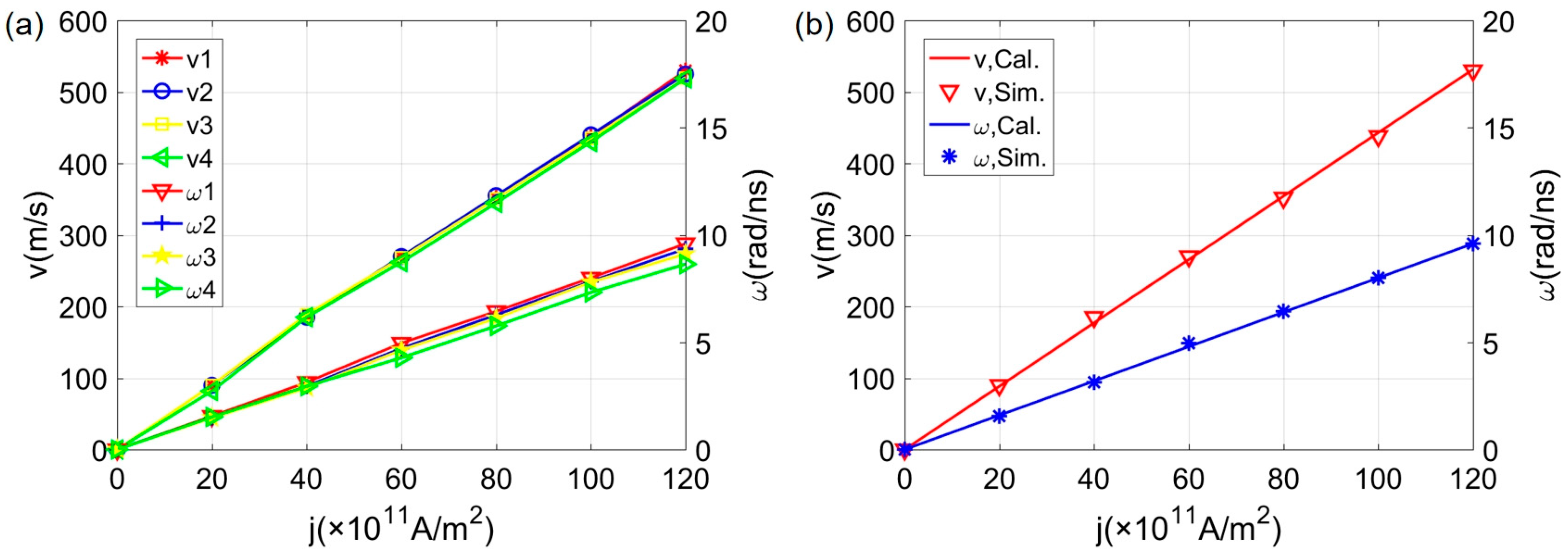
Figure 3 summarizes the numerical data of the skyrmion velocity as a function of the current density. Both the translational speed v and angular speed ω of various amounts of skyrmions are plotted. It is clearly demonstrated in Figure 3a that for the collective motion of two, three and four skyrmions, the current dependence of the skyrmion speed is almost the same as that of a single one. An analytical expression for the current dependence of the motion for a single skyrmion in nanotubes was derived in ref. [24] based on the Thiele equation. Figure 3b compares the numerical result of a single skyrmion in our system to an analytical calculation, which yields a perfect agreement.
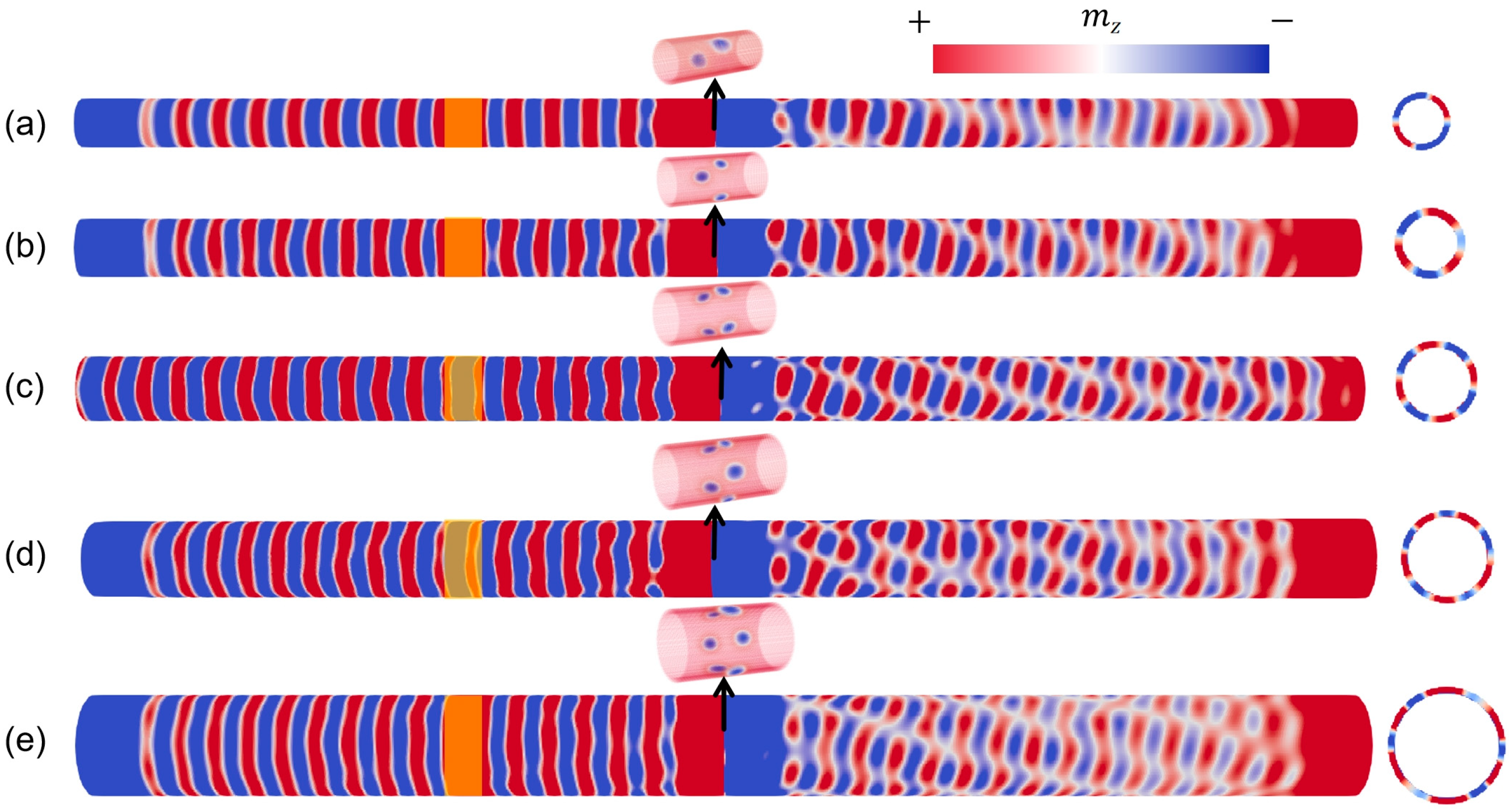
In the following, we focus on the influence of the skyrmion lattice formed in the tube in propagating SWs. As shown in Figure 4, various amounts of skyrmions are positioned in a cross-section in the middle of the tube. In the left part of the tube, a localized rf field is applied in the yellow region, which serves as a SW source. Two branches of SWs are then excited in order to propagate to opposite directions, respectively. The one that propagates to the right will transmit and interact with the skyrmion lattice. The SW mode excited by the rf field is monochromatic, with its frequency equal to the field frequency. Here, the SW mode excited by the rf filed has a uniform spatial distribution in the azimuthal direction, which corresponds to an ordinary planar wave in the flat space. In terms of an order number n defined in the azimuthal direction, such a mode is labeled as the n = 0 mode. The damping parameter α is set to be 0.01 when simulating the spin wave propagating in the tube and to be much larger (1) at the ends of the tube to mitigate the edge effect.
In principle, the SW profile in a tubular geometry can have a non-uniform spatial distribution in the azimuthal direction with n > 0. Due to the periodic boundary condition, n must be an integer number. For the sake of a later discussion, we mention that a mode with n > 0, which forms a circular standing wave in the azimuthal direction, can be considered as the superposition of two eigen modes of the system. By neglecting the thickness dependence, the SW eigen mode in a nanotube is mathematically expressed by A e i ( ω t + l φ k z z ) , where A is the amplitude, ω the angular frequency, k z the wave number and l the integer azimuthal number. For l > 0 (<0), the mode is referred as to an R (L) mode characterized by an azimuthally rotating wave profile, thus analogous to the right-handed (left-handed) circularly polarized light in optics. The superposition of R and L modes with opposite azimuthal numbers thus results in the formation of a standing wave around the tube.
Figure 4 displays the SW profiles after passing through the skyrmion lattices consisting of various numbers of skyrmions, from 2 to 6 in (a)~(e), respectively. Clearly, a significant modification of the SW profile is induced in the process. First of all, the transmitting SW is no longer a planar-wave-like mode anymore. This can be clearly seen by looking at the wave profile in a cross-section of the tube, as demonstrated on the right side of each tube in Figure 4. A non-uniform distribution is acquired in the azimuthal direction, which forms roughly a standing-wave pattern with its order corresponding to the number of the skyrmions that the SW passes through. However, one notices that the nodal lines of the SWs (the white lines in Figure 4) are tilted, not parallel to the axis of the tube as an ordinary wave propagating in a tubular wave guide. The tilting direction is found to be determined by the polarity of the skyrmions. For instance, the nodal lines shown in Figure 4 are all tilted downwards with the magnetization of the skyrmion core pointing inward. In the opposite case, all the nodal lines are tilted upward, with the skyrmion core pointing outward (not shown).

4. Discussion

In the following, we explain the nature of the SWs after passing through the skyrmion lattice observed in our simulations and give a physical understanding of the phenomena.
At first, we demonstrate the nontriviality of this effect by replacing the skyrmions by just some pinholes positioned in a cross-section of the tube. Figure 5 shows the profile of the SW propagating through the middle of the tube containing four holes. As shown by the profile of just one cross-section of the tube, a perfect standing-wave pattern with n = 4 is formed in the azimuthal direction. The nodal lines are parallel to the tube axis without any tilting. This result means that the scattering of the SWs by the skyrmions is fundamentally different with just normal obstacles.
Secondly, we emphasize that the SW effect observed in our case is not the recently reported magnonic activity effect in ferromagnetic nanotubes [39,40]. As aforementioned, a typical SW mode propagating in a tubular geometry is characterized by a standing wave formed in the azimuthal direction. In a longitudinally magnetized tube or a circularly magnetized one with DMI, the location of the standing-wave nodes undergoes a continuous rotation during the propagation of the SW along the tube. This effect, referred to as magnonic activity because of its direct analogy to the optical activity, is originated in the asymmetry between the dispersion relations of the left-(L) and right-handed (R) modes, into which a circular standing wave can be decomposed [39,40]. In our case, however, the SW after transmitting the skyrmion lattice does not form a perfect standing-wave pattern in the cross-section of the tube, as shown in Figure 4. Indeed, magnonic activity does not occur in our case, which will be shown directly later in the paper. The reason is that the tube studied in our case is magnetized in the radial direction, which yields symmetric dispersion relation between the L and R modes.
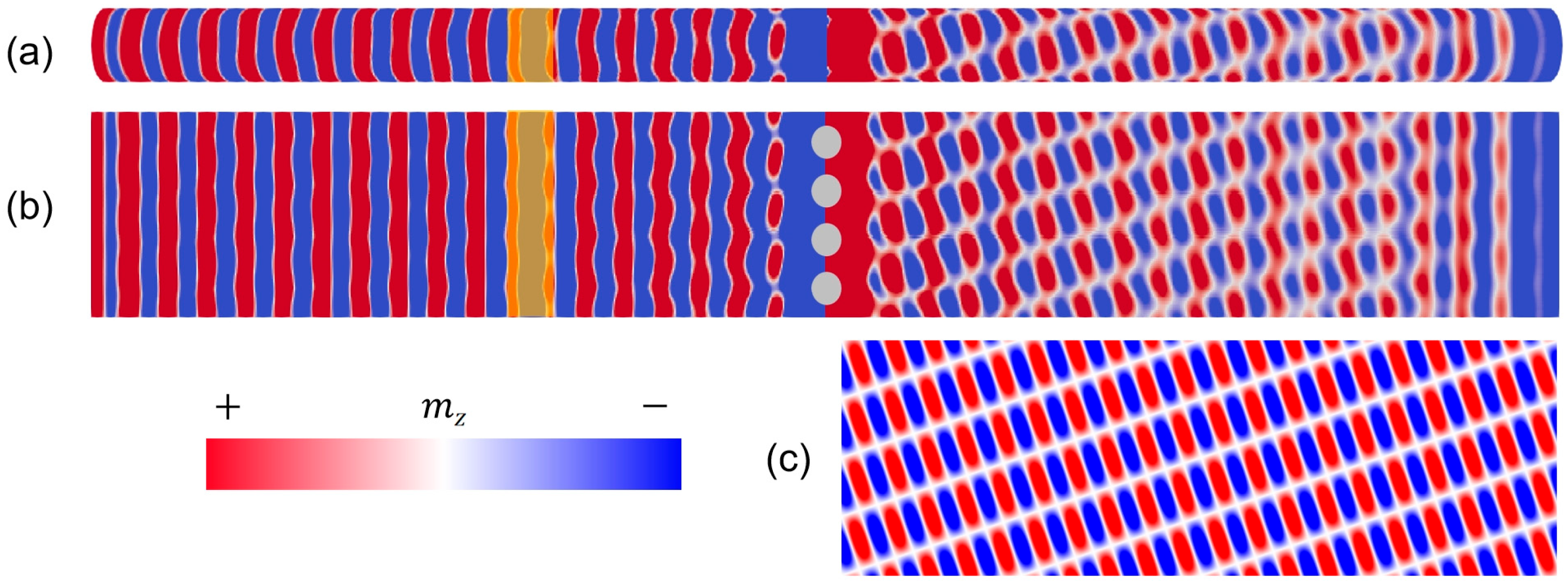
By careful examination, we conclude that the transmitted SWs shown in Figure 4 are superpositions of a planar wave and a circularly polarized mode. This interpretation is unambiguously corroborated in Figure 6, in which the case of a skyrminon lattice with four skyrmions is taken as an example. For better visualization, the tube is mathematically ‘unrolled’ into a flat strip, as shown in Figure 6b. The azimuthal direction of the tube is thus converted to the transverse direction of the strip, with the two lateral boundaries actually connected to each other. The SW before transmission is just a planar wave after unrolling. As shown in Figure 6c, the wave configuration after transmission can be reconstructed artificially by drawing a wave pattern given by
A 1 e i ( ω t k z z + φ 0 ) + A 2 e i ( ω t + 4 φ k z z )
The first term represents a planar wave propagating along the tube with amplitude A1, angular frequency ω , wave number k z and an initial phase φ 0 , and the second term is an R mode with amplitude A2, wave number k z and azimuthal number l = 4. Clearly, such a superposition results in the formation of a non-perfect standing-wave pattern in each cross-section of the tube and the tilt of the nodal lines. As pointed out earlier, the tilting direction is determined by the polarity of the skyrmions. In the mathematical reconstruction, it is described by the sign of the azimuthal number l. This means that the SW scattering by the skyrmion lattice is chiral, yielding either a left- or right-handed mode depending on the polarity of the skyrmions.
The SWs discussed above just become partially circularly polarized after transmission. We observed in our simulations that the SW can sometimes become fully polarized. In Figure 7, an n = 2 mode is excited by an rf field in the left part of the tube and propagates through a skyrmion lattice consisting of four skyrmions. Note that the wave excited is just an ordinary mode expected for a tubular geometry, which does not assume the effect of magnonic activity. Depending on the skyrmion polarity, the transmitted wave becomes either a pure L or R mode, shown in Figure 7a and Figure 7b, respectively.
Finally, we give a physical explanation for the generation of circularly polarized SW modes by the skyrmion lattices. As previously reported [34,35,36], propagating SWs can interact with skyrmions formed in flat samples, causing skew scattering of the SWs. In this process, the skyrmion is driven to move in a direction with an angle relative to the SW propagation direction and the SW wave vector changes its direction correspondingly. The skew direction was found to be dependent on the polarity of the skyrmion. This effect is attributed to the exchange of linear momentum between the SW and skyrmion [34,35]. In our case, it is observed that the skyrmions are also driven to move when SWs propagating the skyrmion lattice formed in the tube. The motion of the skyrmions is identified to be spiraling around the tube (the linear motion is evident in our simulations but the rotational motion is too slow to be quantized due to our limited computational capacity). We point out that the skyrmion speed (in the order of tens m/s) is much less than that of the SW propagation (thousands of m/s). Therefore, the skyrmions can be considered to be stationary in the scattering process.
In such a tubular geometry possessing a cylindrical symmetry, the rotation of the skyrmions implies generation of angular momentum in the direction along the tube axis. Due to the conservation law, the SW must provide the angular momentum acquired by the skyrmions in the process and change its azimuthal number, which is also the quantum number of the magnon angular momentum. The rotational direction, and thus the angular moment of the skyrmion, is determined by its polarity, which also decides the change in the azimuthal number of the SW. This results in the circular polarization of the SWs after scattering with the skyrmions. All the qualitative features observed in the simulations can be understood by considering the exchange of angular momentum between SWs and skyrmions, although an analytical model enabling quantitative calculations is out of scope of this paper. We mention that although a perfect tubular geometry is assumed in our study, the sample simulated actually acquires a surface roughness due to the finite difference approach used in the discretization [45]. This means that our results can tolerate the sample roughness to a certain extent, which in principle can influence the SW modes in ferromagnetic nanostructures [49].

5. Conclusions

In summary, we study, through micromagnetic simulations, the dynamic properties of SWs propagating through a skyrmion lattice formed in a cross-section of ferromagnetic nanotubes. It is found that the SW profiles are significantly altered by the scattering of the skyrmions, bringing about a circular polarization to the transmitted wave, with the handedness associated with the polarity of the skyrmions. The wave profiles obtained in our simulations are successfully reproduced mathematically, supporting our interpretation about the nature of the scattered SWs. This physical effect is attributed to the transfer of angular momentum to the skyrmions by the propagating SWs, causing the change in the azimuthal number of the magnon mode. Our results may bear potential applications in the development of spintronic devices based on orbital angular momentum carried by propagating SWs in ferromagnetic nanostructures [50,51].

Author Contributions

Conceptualization, M.Y. and X.Z.; methodology, M.Y., N.L. and M.F.; software, N.L. and M.F.; validation, M.Y., N.L., M.F. and X.Z.; formal analysis, M.Y, N.L. and M.F.; investigation, N.L, M.F. and M.Y.; resources, M.Y. and X.Z.; data curation, N.L. and M.F.; writing—original draft preparation, M.Y., N.L., M.F. and X.Z.; writing—review and editing, M.Y., N.L., M.F. and X.Z.; visualization, N.L. and M.F.; supervision, M.Y.; project administration, M.Y.; funding acquisition, M.Y. and X.Z. All authors have read and agreed to the published version of the manuscript.

Funding

This work is supported by the National Natural Science Foundation of China (Grant No. 11774218) and Shanghai Key Laboratory of High Temperature Superconductors (Grant No. 14DZ2260700).

Data Availability Statement

Data are contained within the article.

Acknowledgments

Thanks to the anonymous reviewers and editor from the journal.

Conflicts of Interest

The authors declare no conflicts of interest.

References

  1. Roßler, U.K.; Bogdanov, A.N.; Pfleiderer, C. Spontaneous skyrmion ground states in magnetic metals. Nature 2006, 442, 797–801. [Google Scholar] [CrossRef]
  2. Muhlbauer, S.; Binz, B.; Jonietz, F.; Pfleiderer, C.; Rosch, A.; Neubauer, A.; Georgii, R.; Böni, P. Skyrmion lattice in a chiral magnet. Science 2009, 323, 915–919. [Google Scholar] [CrossRef] [PubMed]
  3. Munzer, W.; Neubauer, A.; Adams, T.; Mühlbauer, C.; Franz, F.; Jonietz, R.; Böni, P.; Pedersen, B.; Schmidt, M.; Rosch, A.; et al. Skyrmion lattice in the doped semiconductor Fe1−xCoxSi. Phys. Rev. B 2010, 81, 041203. [Google Scholar] [CrossRef]
  4. Yu, X.Z.; Onose, Y.; Kanazawa, N.; Park, J.H.; Han, J.H.; Nagaosa, N.; Tokura, Y. Real-space observation of a two-dimensional skyrmion crystal. Nature 2010, 465, 901–904. [Google Scholar] [CrossRef] [PubMed]
  5. Derras-Chouk, A.; Chudnovsky, E.M.; Garanin, D.A. Dynamics of the collapse of a ferromagnetic skyrmion in a centrosymmetric lattice. Phys. Rev. B 2022, 105, 134432. [Google Scholar] [CrossRef]
  6. Fert, A.; Cros, V.; Sampaio, J. Skyrmions on the track. Nat. Nanotechnol. 2013, 8, 152–156. [Google Scholar] [CrossRef]
  7. Yu, X.Z.; Kanazawa, N.; Zhang, W.Z.; Nagai, T.; Hara, T.; Kimoto, K.; Matsui, Y.; Onose, Y.; Tokura, Y. Skyrmion flow near room temperature in an ultralow current density. Nat. Commun. 2012, 3, 988. [Google Scholar] [CrossRef]
  8. Iwasaki, J.; Mochizuki, M.; Nagaosa, N. Current-induced skyrmion dynamics in constricted geometries. Nat. Nanotechnol. 2013, 8, 742–747. [Google Scholar] [CrossRef]
  9. Jonietz, F.; Mühlbauer, S.; Pfleiderer, C.; Neubauer, A.; Münzer, W.; Bauer, A.; Adams, T.; Georgii, R.; Böni, P.; Duine, R.A.; et al. Spin transfer torques in MnSi at ultralow current densities. Sciencce 2010, 330, 1648–1651. [Google Scholar] [CrossRef]
  10. Yang, S.H.; Ryu, K.S.; Parkin, S. Domain-wall velocities of up to 750 m s−1 driven by exchange-coupling torque in synthetic antiferromagnets. Nat. Nanotechnol. 2015, 10, 221–226. [Google Scholar] [CrossRef]
  11. Dzyaloshinsky, I. A thermodynamic theory of “weak” ferromagnetism of antiferromagnetics. J. Phys. Chem. Solids 1958, 4, 241–255. [Google Scholar] [CrossRef]
  12. Moriya, T. Anisotropic superexchange interaction and weak ferromagnetism. Phys. Rev. 1960, 120, 91. [Google Scholar] [CrossRef]
  13. Di, K.; Zhang, V.L.; Lim, H.S.; Ng, S.C.; Kuok, M.H.; Yu, J.; Yoon, J.; Qiu, X.; Yang, H. Direct Observation of the DzyaloshinskiiMoriya Interaction in a Pt/Co/Ni Film. Phys. Rev. Lett. 2015, 114, 047201. [Google Scholar] [CrossRef] [PubMed]
  14. Schütte, C.; Iwasaki, J.; Rosch, A.; Nagaosa, N. Inertia, diffusion, and dynamics of a driven skyrmion. Phys. Rev. B 2014, 90, 174434. [Google Scholar] [CrossRef]
  15. Neubauer, A.; Pfleiderer, C.; Binz, B.; Rosch, A.; Ritz, R.; Niklowitz, P.G.; Böni, P. Topological Hall effect in the a phase of MnSi. Phys. Rev. Lett. 2009, 102, 186602. [Google Scholar] [CrossRef]
  16. Yi, S.D.; Onoda, S.; Nagaosa, N.; Han, J.H. Skyrmions and anomalous Hall effect in a Dzyaloshinskii -Moriya spiral magnet. Phys. Rev. B 2009, 80, 054416. [Google Scholar] [CrossRef]
  17. Chen, G. Skyrmion Hall effect. Nat. Phys. 2017, 13, 112–113. [Google Scholar] [CrossRef]
  18. Zang, J.; Mostovoy, M.; Han, J.H.; Nagaosa, N. Dynamics of skyrmion crystals in metallic thin films. Phys. Rev. Lett. 2011, 107, 136804. [Google Scholar] [CrossRef]
  19. Peng, L.; Karube, K.; Taguchi, Y.; Nagaosa, N.; Tokura, Y.; Yu, X. Dynamic transition of current-driven single-skyrmion motion in a room-temperature chiral-lattice magnet. Nat. Commun. 2021, 12, 6797. [Google Scholar] [CrossRef]
  20. Feilhauer, J.; Saha, S.; Tobik, J.; Zelent, M.; Heyderman, L.J.; Mruczkiewicz, M. Controlled motion of skyrmions in a magnetic antidot lattice. Phys. Rev. B 2020, 102, 184425. [Google Scholar] [CrossRef]
  21. Yang, S.; Wu, K.; Zhao, Y.; Liang, X.; Xia, J.; Zhou, Y.; Xing, X.; Zhou, Y. Inhibition of Skyrmion Hall Effect by a Stripe Domain Wall. Phys. Rev. Appl. 2022, 18, 024030. [Google Scholar] [CrossRef]
  22. Wang, X.; Wang, X.S.; Wang, C.; Yang, H.; Cao, Y.; Yan, P. Current-induced skyrmion motion on magnetic nanotubes. J. Phys. D Appl. Phys. 2019, 52, 225001. [Google Scholar] [CrossRef]
  23. Wang, W.; Hu, P.; Kong, L.; Song, D.; Du, H. Magnetic skyrmion Walker breakdown in cylindrical nanotubes. Phys. Rev. B 2023, 107, 134407. [Google Scholar] [CrossRef]
  24. Bao, B.; Yang, M.; Yan, M. Asymmetric motion of magnetic skyrmions in ferromagnetic nanotubes induced by a magnetic field. Symmetry 2022, 14, 1195. [Google Scholar] [CrossRef]
  25. Holanda, J. Analyzing the magnetic interactions in nanostructures that are candidates for applications in spintronics. J. Phys. D Appl. Phys. 2021, 54, 245004. [Google Scholar] [CrossRef]
  26. Jamali, M.; Kwon, J.H.; Seo, S.M.; Lee, J.; Yang, H. Spin wave nonreciprocity for logic device applications. Sci. Rep. 2013, 3, 3160. [Google Scholar] [CrossRef]
  27. Chumak, A.V.; Vasyuchka, V.I.; Serga, A.A.; Hillebrands, B. Magnon spintronics. Nat. Phys. 2015, 11, 453–461. [Google Scholar] [CrossRef]
  28. Cornelissen, L.J.; Liu, J.; Duine, R.A.; Ben Youssef, J.; van Wees, B.J. Long-distance transport of magnon spin information in a magnetic insulator at room temperature. Nat. Phys. 2015, 11, 1022–1026. [Google Scholar] [CrossRef]
  29. Liu, C.P.; Chen, J.L.; Liu, T.; Heimbach, F.; Yu, H.M.; Xiao, Y.; Hu, J.F.; Liu, M.C.; Chang, H.C.; Stueckler, T.; et al. Long-distance propagation of short-wavelength spin waves. Nat. Commun. 2018, 9, 738. [Google Scholar] [CrossRef]
  30. Chumak, A.V.; Serga, A.A.; Hillebrands, B. Magnon transistor for all-magnon data processing. Nat. Commun. 2014, 5, 4700. [Google Scholar] [CrossRef]
  31. Zhang, X.; Ezawa, M.; Xiao, D.; Zhao, G.P.; Liu, Y.; Zhou, Y. All-magnetic control of skyrmions in nanowires by a spin wave. Nanotechnology 2015, 26, 225701. [Google Scholar] [CrossRef] [PubMed]
  32. Zhang, X.; Müller, J.; Xia, J.; Garst, M.; Liu, X.; Zhou, Y. Motion of skyrmions in nanowires driven by magnonic momentum-transfer forces. New J. Phys. 2017, 19, 065001. [Google Scholar] [CrossRef]
  33. Bo, L.; Hu, C.; Kong, L.; Ji, L.; Li, Y.; Zhang, J.; Zhao, R.; Zhang, X. Velocity increase of skyrmion motion by constructing wedge nanotracks. J. Magn. Magn. Mater. 2022, 546, 168877. [Google Scholar] [CrossRef]
  34. Schütte, C.; Garst, M. Magnon-skyrmion scattering in chiral magnets. Phys. Rev. B 2014, 90, 094423. [Google Scholar] [CrossRef]
  35. Iwasaki, J.; Beekman, A.J.; Nagaosa, N. Theory of magnon-skyrmion scattering in chiral magnets. Phys. Rev. B 2014, 89, 064412. [Google Scholar] [CrossRef]
  36. Ma, X.; Ai, X.; Yang, X.; Cai, M.; Shim, J.; Piao, H. Gyromotion of skyrmion along the nanofilm edge driven by spin waves. J. Magn. Magn. Mater. 2023, 581, 170665. [Google Scholar] [CrossRef]
  37. Otálora, J.A.; Yan, M.; Schultheiss, H.; Hertel, R.; Kákay, A. Curvature-Induced Asymmetric Spin-Wave Dispersion. Phys. Rev. Lett. 2016, 117, 227203. [Google Scholar] [CrossRef]
  38. Otálora, J.A.; Yan, M.; Schultheiss, H.; Hertel, R.; Kákay, A. Asymmetric spin-wave dispersion in ferromagnetic nanotubes induced by surface curvature. Phys. Rev. B 2017, 95, 184415. [Google Scholar] [CrossRef]
  39. Yang, M.; Yin, B.; Li, Z.; Zeng, X.; Yan, M. magnonic activity of ferromagnetic nanocylinders. Phys. Rev. B 2021, 103, 094404. [Google Scholar] [CrossRef]
  40. Yang, M.; Zeng, X.; Yan, M. Magnonic activity of circularly magnetized ferromagnetic nanotubes induced by dzyalonshinskii-moriya interaction. Symmetry 2022, 14, 1771. [Google Scholar] [CrossRef]
  41. Slonczewski, J.C. Current-driven excitation of magnetic multilayers. J. Magn. Magn. Mater. 1996, 159, L1–L7. [Google Scholar] [CrossRef]
  42. Zare, M. Resonance spin-transfer torque in ferromagnetic/normal-metal/ferromagnetic spin-valve structure of topological insulators. J. Magn. Magn. Mater. 2019, 492, 165605. [Google Scholar] [CrossRef]
  43. Gilbert, T.L. A Lagrangian formulation of the gyromagnetic equation of the magnetization field. Phys. Rev. 1955, 100, 1243. [Google Scholar]
  44. Zhang, S.; Li, Z. Roles of Nonequilibrium Conduction Electrons on the Magnetization Dynamics of Ferromagnets. Phys. Rev. Lett. 2004, 93, 127204. [Google Scholar] [CrossRef] [PubMed]
  45. Vansteenkiste, A.; Leliaert, J.; Dvornik, M.; Helsen, M.; Garcia-Sanchez, F.; Van Waeyenberge, B. The design and verification of MuMax3. AIP Adv. 2014, 4, 107133. [Google Scholar] [CrossRef]
  46. Sampaio, J.; Cros, V.; Rohart, S.; Thiaville, A.; Fert, A. Nucleation, stability and current-induced motion of isolated magnetic skyrmions in nanostructures. Nat. Nanotechnol. 2013, 8, 839–844. [Google Scholar] [CrossRef]
  47. Xie, K.; Sang, H. Three layers of skyrmions in the magnetic triple-layer structure without the Dzyaloshinsky-Moriya interaction. J. Appl. Phys. 2014, 116, 223901. [Google Scholar] [CrossRef]
  48. Holanda, J.; Campos, C.L.A.V.; Franca, C.A.; Padrón-Hernández, E. Effective surface anisotropy in polycrystalline ferromagnetic nanowires. J. Alloys Compd. 2014, 617, 639–641. [Google Scholar] [CrossRef]
  49. Abeed, M.A.; Sahoo, S.; Winters, D.; Barman, A.; Bandyopadhyay, S. The effect of material defects on resonant spin wave modes in a nanomagnet. Sci. Rep. 2019, 9, 16635. [Google Scholar] [CrossRef]
  50. Yan, P.; Kamra, A.; Cao, Y.; Bauer, G. Angular and linear momentum of excited ferromagnets. Phys. Rev. B 2013, 88, 144413. [Google Scholar] [CrossRef]
  51. Jiang, Y.; Yuan, H.; Li, Z.; Wang, Z.; Zhang, H.; Cao, Y.; Yan, P. Twisted Magnon as a Magnetic Tweezer. Phys. Rev. Lett. 2020, 124, 217204. [Google Scholar] [CrossRef] [PubMed]
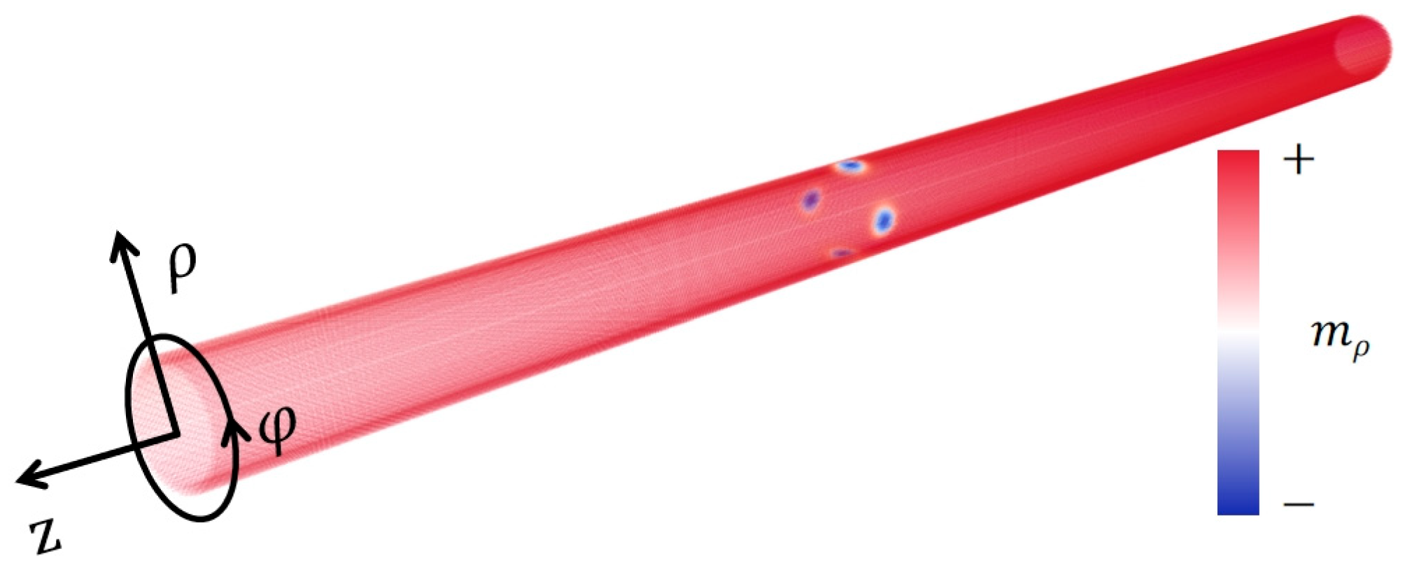
Figure 1. A Stable state of 4 magnetic skyrmions (blue dots) formed in a cross-section of a Co/Pt cylindrical nanotube obtained in micromagnetic simulations. The tube is 1000 nm long, with a 25 nm outer radius and 4 nm thickness. A cylindrical coordinate system used in the paper is also drawn here.
Symmetry 16 01336 g001
Figure 2. A synchronous spiraling motion of 2 skyrmions (trajectories indicated by the yellow lines) driven by an electric current observed in micromagnetic simulations. The 2 skyrmions are initially formed in a cross-section of a tube with a 25 nm outer and 21 nm inner radii.
Symmetry 16 01336 g002
Figure 3. (a) Numerical data of the translational speed v and angular speed ω of multiple skyrmions as a function of the current density. The index of v and ω indicates the number of skyrmions that move together. The lines are used to connect the data points. (b) Comparison of the simulated skyrmion speeds (dots) and theoretical calculations (lines). In the calculations, a spin polarization rate P = 0.5 and non-adiabaticity parameter β = 0.5 are used for the electrical current [24].
Symmetry 16 01336 g003
Figure 4. SW profile modification when passing through a skyrmion lattice formed in a cross-section of the tube. A n = 0 SW mode is excited by an rf field located in the yellow region. The right-running SW transmits a skyrmion lattice composed of 2~6 skyrmions, as shown in (ae), respectively. A cross-section of the right-half of the tube is displayed in each case, showing imperfect standing-wave patterns of the SW after passing through the skyrmions. The frequency of the rf field is 120 GHz in (a) and 140 GHz in (be).
Symmetry 16 01336 g004
Figure 5. Instead of 4 skyrmions, 4 pinholes were positioned in a cross-section of the tube. The same SW mode is excited as in Figure 4 by an rf field located in the yellow region. After propagating through the holes, a conventional wave configuration in a wave guide is observed, showing a perfect standing-wave pattern formed in the cross-section of the tube. The frequency of the rf field is 140 GHz.
Symmetry 16 01336 g005
Figure 6. For a better visualization of the SW pattern, tube (a) is “unrolled” into a flat strip (b) with the lower and upper edges are actually the same. The SW is excited by an rf field applied in the yellow region in the left half of the tube. Clearly, the SW is a planar wave before transmitting the skyrmion lattice consisting of 4 skyrmions indicated by the gray dots in (b). The wave pattern after passing through the skyrmion lattice is reconstructed artificially by the superposition of a planar wave and a circularly polarized wave, as shown in (c). The mathematical expression of the wave superposition is given in Equation (2). The frequency of the rf field is 140 GHz.
Symmetry 16 01336 g006
Figure 7. A n = 2 SW mode excited by an rf field in the left part of the tube, which passes through a skyrmion lattice consisting of 4 skyrmions. Depending on the polarity of the skyrmions, the transmitting wave becomes either a purely left-handed (a) or right-handed (b) circularly polarized mode. The frequency of the rf field is 120 GHz.
Symmetry 16 01336 g007
Disclaimer/Publisher’s Note: The statements, opinions and data contained in all publications are solely those of the individual author(s) and contributor(s) and not of MDPI and/or the editor(s). MDPI and/or the editor(s) disclaim responsibility for any injury to people or property resulting from any ideas, methods, instructions or products referred to in the content.