Article

Adaptive Feedback Control of Nonminimum Phase Boost Converter with Constant Power Load

1
Laboratory of Advanced Systems, Polytechnic School of Tunisia (EPT), B.P. 743, Marsa 2078, Tunisia
2
Department of Electrical Engineering, College of Engineering, University of Business and Technology (UBT), Jeddah 21361, Saudi Arabia
*
Author to whom correspondence should be addressed.
Symmetry 2024, 16(3), 352; https://doi.org/10.3390/sym16030352
Submission received: 20 January 2024 / Revised: 21 February 2024 / Accepted: 28 February 2024 / Published: 14 March 2024
(This article belongs to the Special Issue Active Control of Asymmetrical Wake Flow in Wind Energy Systems)

Abstract

:
The inherent negative impedance characteristics of a Constant Power Load (CPL) pose a potential threat to the stability of the bus voltage in a DC microgrid consisting of a symmetrical parallel boost converter. We suggest an adaptive feedback control technique using the input–output exact feedback linearization theory for a boost converter integrated into a DC microgrid to improve the stability of the DC bus voltage. This approach involves a transformation of the model into a Brunovsky canonical form, effectively addressing the nonlinear challenges arising from the CPL and the nonminimum phase characteristics of the boost converter. Subsequently, guided by the Lyapunov approach, an adaptation law is established to fine-tune the controller’s gain vector, facilitating the tracking of a predefined linearizing feedback control. We methodically create a method to choose the gains of the adaptive controller in order to guarantee an adequate output response. We validate our suggested controller’s performance using simulation.

1. Introduction

Power system modeling and analysis are related to symmetry in the shift from conventional power networks to smart grids. Because they enable impedance coupling in electric source and load connections, electronic converters are frequently used in modern electronics. Asymmetrical electrical designs often increase unique features for better overall performance.
In modern times, power electronic converters play a pivotal role in advanced electrical systems for vehicles and DC microgrids, as documented in works such as [1,2,3,4,5]. Within DC-distributed power systems, these converters are often connected in a cascaded manner. Some of these converters serve as closely regulated loads, consuming constant power and behaving as what are known as constant power loads (CPLs). These CPLs exhibit negative incremental impedances, which can result in severe instability issues, posing a significant challenge in the development of stabilizing controllers forsupplying DC-DC converters.
In the literature, you can find a multitude of controller designs for DC-DC converters that provide power to CPLs. For instance, active damping techniques were introduced in [6], while passive damping approaches were employed in [7,8,9] to counteract the destabilizing effects of CPLs in DC-DC power converters.
References [10,11] provide passivity-based control solutions for a boost converter that consider the load dynamics similar to a mainly constant power load. The passivity-based controller derived from these works takes the form of a nonlinear inverse quadratic proportional derivative (PD) controller [10,12]. An adaptive output feedback controller for a boost converter is proposed in work [13] in order to rebuild the load conductance and inductor current.
However, it is essential to acknowledge that passivity-based control exhibits a notable drawback: It is limited to systems with a relative degree of one and weakly minimum phase systems, at the very least [14]. The authors of [10] difficulty that the unstable internal dynamics of the boost converter present stability challenges for the suggested passivity-based controller. Moreover, controllers derived from PD principles are susceptible to issues related to noise.
An alternative approach, as presented in [11], introduces passivity-based control with interconnection. Nonetheless, this implementation has its own limitation; it is organized for a specific operating point of the constant power load [15]. In summary, passivity-based control exhibits limited noise suppression primarily because of the presence of a differentiator, and it tends to respond slowly [15]. On the other hand, references [16,17,18,19,20] provide alternative nonlinear control methods, including sliding mode control, synergetic-based control, current mode control, and model predictive control. Sliding mode control, owing to its straightforward implementation and robustness, finds extensive applications and has been employed in the stabilization of DC-DC converters and the mitigation of instabilities caused by constant power loads (CPLs) [15,21,22]. Nonetheless, a significant drawback of sliding mode control is the phenomenon known as “chattering” and variable switching frequencies, which can impact the filtering requirements of the DC-DC boost converter. Furthermore, sliding mode control is a form of inversion control that necessitates the internal dynamics to possess stability.
In [23], synergetic based regulation is used; however, a disadvantage of this approach is that it is highly susceptible to noise of high frequencies. In [16], current mode control has been studied with an emphasis on system stability analysis in a small-signal setting.
Model predictive control has also been explored for the stabilization of multi-converter systems supplying CPLs, representing a relatively new avenue for researchers with many challenges yet to be fully addressed [20].
In theory, feedback linearization has the potential to offset any degree of constant power load (CPL) and achieve system stabilization in a comprehensive, large-signal context, as supported by references [15,24]. Feedback linearization typically revolves around the pursuit of a nonlinear feedback mechanism that, when applied, effectively nullifies the system’s inherent nonlinearity. This, in turn, allows for the application of conventional linear control techniques in controller design [21]. However, the application of feedback linearization is conventionally restricted to nonminimum phase systems. In the case of a nonminimum phase boost converter, this limitation can be overcome by circumventing the minimum phase requirement through the application of an input-state linearization approach instead of input_output linearization, as discussed in [25].
It is important to note, however, that input-state linearization has a major limitation in that it is not the best option for output tracking control unless there is a way to describe the reference states in terms of the reference output trajectory. An alternative method for controlling nonminimum phase boost converters involves the regulation of the output voltage by indirectly regulating the inductor current, as proposed in [26]. The issue with indirect regulation lies in its inability to shape the output response effectively. The response of the output voltage follows the open-loop dynamics, leading to slower response times and potential overshooting or undershooting. Moreover, this method exhibits high sensitivity to changes in circuit parameters and variations in the load, as highlighted in references [27,28]. An alternative approach to regulating nonminimum phase systems involves redefining the output in a way that transforms the system, with respect to this redefined output, into a minimum-phase system, as suggested in [29,30,31,32].
In [33], exact linearization is used as an output redefinition technique to control the DCDC boost converter. It achieves this by redefining the system’s output as a linear combination of inductor current and output current, effectively converting it into a minimum phase system. However, a notable drawback is the presence of significant output voltage errors in steady-state. Additionally, precise knowledge of the load resistance is required when calculating the reference current, and this parameter can vary, potentially complicating implementation for constant power loads (CPLs). Furthermore, the system is susceptible to transitioning between minimum and nonminimum phase states during transient conditions, which may share similar limitations with non direct voltage control. The use of voltage mode control in [34] and a loop-cancellation technique in [24] are two examples of active damping methodologies that use feedback linearization. But, the way it is described in [24] uses a highly noise-sensitive differentiator block and a reciprocal block, both of which can be difficult to apply. Furthermore, by adding a new state to the system’s modeling, this approach makes the system more complex. In [34], the authors employ an active damping method to establish small-signal stability. It is important to mention that the strategies outlined in [24,34] do not modify the internal dynamics of the system, which leads to a system that is band-limited and, as a result, responds more slowly. Stable Shortest Horizon FCS-MPC Output Voltage Control in Nonminimum Phase Boost-Type Converters Based on Input-State Linearization is an alternate method that is introduced in [35].
However, in order to ensure proper system functioning, a short-horizon FCS-MPC controller based on input-state linearization is suggested. This implementation must address the issue of the unstable internal dynamic.
Additional research exploring input-output feedback linearization methods can be found in references [24,36,37,38]. In [24,36], the stabilization of a boost converter is achieved for a combination load comprising a constant power load and a resistive load.
The authors in [39] use a full-order feedback controller for applying feedback linearization using coordinate transformation for a system that is solely CPL-driven.
The previous literature review shows that the origin instability issues introduced by a boost converter with a CPL can be traced to the nonminimum phase behavior. It has been found that nonminimum phase behavior imposes limits on the control performance, and the stability of dynamical systems is difficult to control.
It is evident that there is no universal solution to these challenges, and further research is essential in this domain.
In order to address the challenges outlined above, this paper introduces an innovative adaptive feedback nonlinear control approach. This approach combines the Input–Output Exact Feedback Linearization technique with the Lyapunov approach to control a nonminimum phase boost converter system that supplies power to a constant power load (CPL).
The method we propose involves a redefinition of the output by introducing a current signal into the node voltage. This transformation converts the system model into a canonical Brunovsky form. Our approach focuses on adjusting the gain vector of a nonlinear adaptive controller as the control procedure unfolds. We aim to update this gain vector through a suitable adaptation law, enabling the adaptive control to closely follow a predetermined input_output feedback linearizing controller. By employing the principles of Lyapunov theory, we establish that the desired trajectory can be effectively tracked by the output signal.
By taking the boost converter with a CPL as our control subject, we thoroughly analyze the design steps of our proposed control strategy. Ultimately, we validate the effectiveness of our proposed controller through simulations.
The paper is structured as follows: Section 2 introduces the establishment of the affine nonlinear model for the boost converter with a constant power load in a DC microgrid. Section 3 delves into a discussion on the zero dynamic stability of the system under varying output functions, all based on the input_output feedback linearizing controller technique. In Section 4, we put forth the nonlinear adaptive strategy and present proof of the global asymptotic stability of the closed-loop system, drawing upon the principles of Lyapunov stability theory. Simulation results are reported in Section 5. Finally, in Section 6, we provide our concluding remarks.

2. System Description and Modeling

2.1. System Description

A typical DC microgrid configuration is seen in Figure 1 [13]. Through a DC-DC converter, the DC source supplies the necessary voltage for the DC bus, and several electronic loads attached to the DC bus, such as the controlled rectifier or the inverter, can be regarded as CPLs. In order to guarantee the appropriate operation of the different loads, the bus voltage supplies a constant power to the CPLs as well as a constant voltage for the resistive load.
The DC bus voltage may fluctuate, and, possibly, the entire DC microgrid may become unstable due to the CPL’s negative impedance characteristics, variations in the load, and changes in the distributed power source. A condensed DC distribution system is displayed in Figure 2. The resistive load and the CPL are linked in parallel to the DC bus in the system, which is powered by the distributed power supply through a boost converter.
Where E is the distributed power supply’s total input voltage, Lfil is its filter inductor, Cf is its filter capacitor, R is its total resistive load, Vbus is its bus voltage, I L f i l is the filter inductor current, PCPL is its lumped constant power load, Io is its output current, Dd is its diode, and Qs is its switching device. IP = PCPL/Vbus, where IP is the instantaneous value of the CPL’s input current, gives the voltage current characteristics of a CPL.

2.2. Modeling System

As shown in Figure 2, assuming that the system operates in Continuous Current Mode (CCM), state space averaging is used to create the average model of the boost converter with a CPL, which can be expressed by the following equations:
d I L f i l d t =       V b u s L f i l   +     E L f i l +     V b u s L f i l d   d V b u s d t   =           V b u s R C f   +     I L f i l C f           P b u s C f   V C     I L f i l C f d
where d is the duty cycle.
Let x 1 x 2 T   =   I L f i l V b u s T and u = d, then the Equation (1) can be rewritten as follows:
d x 1 d t   =       x 2 L f i l   +     E L f i l +     x 2 L f i l u   d x 2 d t   =           x 2 R C f   +     x 1 C f           P C P L C f   x 2     x 1 C f u
The following dynamical form is used to write the model (2) that represents the dynamics of a DC distribution system:
x ˙ =   f x   +   g x   u y   =   h x
With f x =         x 2 L f i l   +     E L f i l       x 2 R C f   +     x 1 C f           P C P L C f   x 2   and g x =     x 2 L f i l     x 1 C f .

3. System Analysis and Problem Formulation

3.1. System Analysis

With respect to the nonlinear affine model presented in (2), if the two conditions listed below satisfy [13], there is without any question a set of output functions h(x) that correspond to the achievement of the following linearization criteria: the total number of orders r equals the number of dimensions n of the system at x = x0, and the relative order of this system has a definition.
(i).
The rank of the matrix g x     a d f g x         a d f n 2 g x     a d f n 1 g x is constant and equal to n for any x near x0.
(ii).
The vector field set g x     a d f g x         a d f n 2 g x   is involutory at x = x0.
A function f(x) is required in order to accurately linearize the degree of connection r of the provided system on an open set of x = x0 into a controlled linear Brunovsky canonical form [19]. Here, denotes the Lie bracket a d f g x of the vector fields g(x) and f(x), respectively.
If the system (2) does not succeed in satisfying all of the linearization criteria (i) and (ii), it will develop unstable zero dynamics and turn into a nonminimum phase system.

3.2. Problem Formulation

The concept of input_output feedback linearization has been well-established in the literature on nonlinear control systems [13].
The output (y) of a Single Input Single Output nonlinear system (3) is differentiated until the control input (u) appears in the resultant equation in order to apply input_output feedback linearization to the system. The relative degree (r) is equivalent to how often the output is differentiated. The dynamics of a nonlinear system may be divided into an internal subsystem (n–r dimension unobservable) and an exterior linear subsystem (input_output of r dimension) when a coordinate transform is used. The system’s order is represented by ‘n’ in this case. With linear state feedback control, the linear subsystem is stabilized. When the states of the linear subsystem are at rest, the dynamics of the unobservable subsystem, also known as zero dynamics, describe the internal dynamics [5,13].
If we use the capacitor voltage as the output function, then y = x 2 . The nonlinear system (2) has a relative degree of r = 1, which is lower than the system’s order n = 2.
The dynamics of the system (2) are, therefore, split into an internal, unobservable component and an input_output component. The boost converter with the CPL model will be changed to the normal form by utilizing the change of state transformation as follows:
T x   =     ξ x z x
In order to resolve the following equation, an expression of the dynamic compensator z(x) is determined in accordance with the input_output feedback linearization theory [19]:
L g z x =   0
Equation (6), which reads as follows, translates to a potential resolution to this issue:
z x =   C f 2 x 2 2     +     L f i l 2 x 1 2
Consequently, the following is the system’s internal dynamic equation:
z ˙ x =   P C P L + ξ 2 R     +     E C f 2 ξ 2     +     L f i l 2 z 1 2
Allowing for ξ = 0 , the system’s zero dynamics are as follows:
z ˙ x =       P C P L     +     E     L f i l 2 z 1 2
The Jacobian matrix and an equilibrium point may both be determined using the formulas Υ =       L f i l P C P L 2 2 E 2 and z ˙ z =       E 2 2 z L f i l 1 2 , respectively, as shown in Equation (8). Since the eigenvalue of Equation (8) at the Υ is equal to λ = E 2 P C P L L f i l and is situated in the right half of the complex plane, the zero dynamics given in Equation (6) is unstable. As a result, when the capacitor voltage serves as the system output feedback value, the system is a nonminimum phase.

4. Nonlinear Adaptative Feedback Controller

As can be shown from the analysis above, an unstable boost converter system with unstable internal dynamics cannot have input_output feedback linearization applied except, as was said in Section 3.2, by stabilizing the internal dynamics.
In order to comply with the constraints of input_output feedback linearization, we redefine the output function h(x).
As a result of the analysis above, h(x) may be thought of as the following:
y =   1 2 C f   x 2 2     +     L f i l   x 1 2
The control variable (u) is subjected to the concepts of precise input-output feedback linearization and Lyapunov stability theory in order to stabilize the zero dynamics (6) and create a control structure that enables asymptotic output tracking. Therefore, by adjusting the inductor current and capacitor voltage, the stability of the bus voltage may be indirectly managed.
Our main objective is to design a Lyapunov controller that, due to its performance in output tracking, mimics a predefined input_output linearizing controller.
First of all, we derive the output y =   1 2 C f   x 2 2     +     L f i l   x 1 2 to the relative degree
y ˙   = C f x 2       x 2 R C f   +     x 1 C f           P C f   x 2     x 1 C f u   +     L f i l   x 1       x 2 L f i l   +     E L f i l +     x 2 L f i l u           =       x 2 2 R   P C P L +   E x 1           =   L f   h x y ¨   =     2   x 2 R       x 2 R C f   +     x 1 C f           P C P L C f   x 2     x 1 C f u   + E       x 2 L f i l   +     E L f i l +     x 2 L f i l u         = E E     x 2 L f i l   2   x 2 R C f   x 1     x 2 R     P C P L x 2   + E L f i l   +   2 x 1 x 2 R C f   u       =   L f 2 h x   +   L g L f x u
The order of the system (2) corresponds to the relative degree r = 2 in the relationship.
The boost converter with the CPL model will be changed to the normal form by utilizing the change of state transformation as follows:
T x   =   ξ 1 x ξ 2 x       =         1 2 C f   x 2 2     +     L f i l   x 1 2       x 2 2 R   P C P L +   E x 1    
The nonlinear system (2) may be made linear in Brunovsky canonical form by applying the coordinate transformation (11) as shown below:
ξ ˙ 1 =   ξ 2 ξ ˙ 2   =   L f 2 h x   +   L g L f h x u I o l = v  
where ξ 2 and ξ 1 are state variables of converted linear systems (12) and the relationship between the new control variable v and the existing nonlinear boost converter system’s control variable u is as follows:
u I o l x   =   E E     x 2 L f i l   + 2   x 2 R C f   x 1     x 2 R     P C P L x 2   +   v E L f i l   +   2 x 1 x 2 R C f
The tracking error and its first derivative are defined as follows using the Lyapunov design idea:
e 1   =   ξ 1   ξ r e f     e 2   =   ξ 2   ξ ˙ r e f  
where ξ r e f is the reference trajectory using the state transformation (11) and the linearized feedback control (13), the system (12) is written as follows:
e ˙ 1         = e 2       e ˙ 2   = L f 2 h x + L g L f 1 h x   u I O L ξ ¨ r e f  
and we choose an input–output linearizing controller:
u I o l =   1 L g L f 1 h x   L f 2 h x   + ξ ¨ r e f   +   k 1 e 1     +   k 2 e 2
With K   =   k 1   k 2 T , the closed-loop system can be written as e ˙ = A c e :
e ˙ 1 e ˙ 2 = 0 1 k 1 k 2   e 1 e 2
Should K be a Hurwitz vector, that is, all the roots of the polynomial P s   = s 2   +   k 2 s     +     k 1 have negative real parts, then the error is stable at the origin.
To perform this, we choose an input_output linearizing controller:
u I o l x   =   R   C f L f i l E C f R   + 2   L f i l x 1 x 2     E E     x 2 L f i l   + 2   x 2 R C f   x 1     x 2 R     P C P L x 2   +   ξ ¨ r e f   3 e 1 4.3   e 2  
Consequently, the closed-loop system is made linear, and one has the following:
e ˙ 1 e ˙ 2 = 0 1 3 4.3   e 1 e 2
However, it is possible that nonlinear controllers do better overall than linear controllers at regulating nonlinear systems. The implementation of the nonlinear component, in addition to the requirement for precise knowledge of the system model, is one of the key limitations of the input_output linearizing controller. Here, we propose the creation of an adaptive feedback controller as a solution to this issue.
The following adaptive feedback controller analytical formulation is taken into consideration:
u I o l   =   Γ T e t Γ T =     Γ 1 Γ 2
in which Γ is adjusted so that we have in the limit
u A d a p t a t i v e   =   Γ ˜ T e t =     u I o l
The ideal gain vector is indicated by an asterisk in Γ ˜ . The following equation is created by replacing off u ˜ A d a p t a t i v e in Equation (12):
ξ ˙ 2   = L f 2 h x   +   L g L f h x u A d a p t a t i v e
The following is a rewrite of this equation:
ξ ˙ 2   =   ξ ¨ r e f     3 e 1 4.3 e 2       E C f R   + 2   L f i l x 1 x 2 R C f L f i l u I o l   u A d a p t a t i v e
As a result, we obtain the following:
e ˙ 1 =   e 2 e ˙ 2 =     3   e 1 4.3   e 2   +   E C f R   + 2   L f i l x 1 x 2 R C f L f i l   Γ ˜   Γ T e 1 e 2 T
If we define A   =   0 0 3 4.3 and B   =   0 E C f R   + 2   L f i l x 1 x 2 R C f L f i l
As a result, the closed-loop system (24) below is obtained:
e ˙ 1 e ˙ 2 e ˙   =     0 0 3 4.3 A   e 1 e 2 e       +         0 E C f R   + 2   L f i l x 1 x 2 R C f L f i l B   Γ ˜ 1 Γ 1 Γ ˜ 2 Γ 2 T Γ ˜       Γ   T e 1 e 2 e
It should be demonstrated that because is Hurwitz stable, there exists a positive definite matrix for any positive definite matrix that fulfills the next Lyapunov equation:
A   T   P     +     P   A     =         Q
We use a Lyapunov candidate function with respect to system (25):
V   e   ,   Γ     =   e T   P   e       +       1 γ   Γ ˜       Γ     T     Γ ˜       Γ  
By adjusting Γ so that, the adaptive feedback controller u A d a p t a t i v e     =     Γ T   e   t is thus effectively specified,
Γ     =     γ   0 t e   t T   P   B     e   t       d t Γ     0
As a result, the output of the adaptive feedback controller may be expressed as follows:
u A d a p t a t i v e   =   Γ 1   ξ 1     ξ 1 r e f   +   Γ 2   ξ ˙ 1     ξ ˙ 1 r e f
where
Γ 1   =   0.56 R C f L f i l E C f R   + 2   L f i l x 1 x 2   0 t 7.34 ξ 1     ξ 1 r e f 2   + 10.32 ξ 1     ξ 1 r e f   ξ ˙ 1     ξ ˙ 1 r e f   d t  
and
Γ 2   =   0.45 R C f L f i l E C f R   + 2   L f i l x 1 x 2   0 t 8.64 ξ 1     ξ 1 r e f   ξ ˙ 1     ξ ˙ 1 r e f   + 9.44 ξ ˙ 1     ξ ˙ 1 r e f 2   d t  
The adaptative feedback controller in (29) is utilized to validate the system represented in (12), and the closed-loop system (25) is Lyapunov stable. Along the trajectories of (25), the time derivative of V ˙   e   ,   Γ   is provided with
V ˙   e   ,   Γ     =   e T   A   T P     +     P   A e       +   2   e T   P   B       Γ ˜       Γ   T e           2 γ   Γ ˜       Γ   T Γ ˙                                     =     e T   Q   e     2   Γ ˜       Γ   T       Γ ˜ γ       e T   P   B                                    
if we select Γ ˙   =   γ e T P   B , then
V ˙   e   ,   Γ     =     e T   Q   e     <   δ m i n Q   e 2  
where δ m i n Q is lowest eigenvalue of Q.
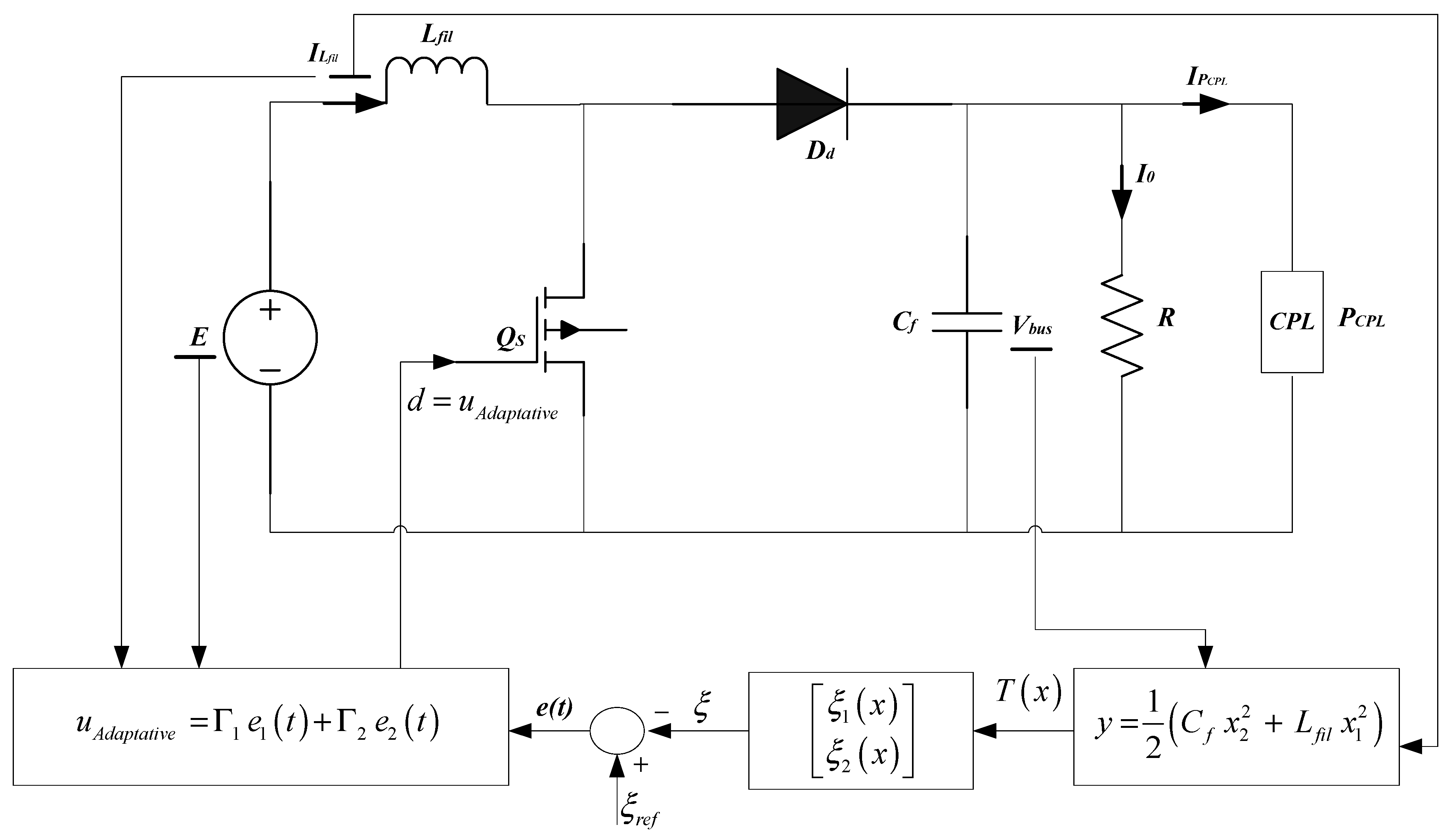
Once the system (12) reaches global stability, the suggested adaptive feedback controller’s design is complete. The parameters Γ 1   , Γ 2   , and γ values can be changed to enhance the system’s dynamic quality. Figure 3 displays the control block diagram for it.

Remarks

According to the working principle and actual working conditions of the boost converter with a CPL, the variation in the inductance of the filter, capacitor, and load is limited. The adaptive controller proposed above has an advantage in that knowledge of external disturbances is not necessary to build the controller. This control method guarantees robustness. To this end, the proposed control algorithm is designed with the control objective of enabling the system to accurately track the target value under the influence of unknown disturbances.

5. Simulation Results

Using the MATLAB/Simulink platform, a system simulation model was created in this study to evaluate the effects of the nonlinear adaptive feedback control strategy, as shown in Figure 3. Vin = 12 V, Vcref = 24 V, L = 1 mH, C = 100 μF, R = 50 Ω, fs = 50 kHz, and PCPL = 10 W are the system’s simulation parameters.

5.1. Case 1

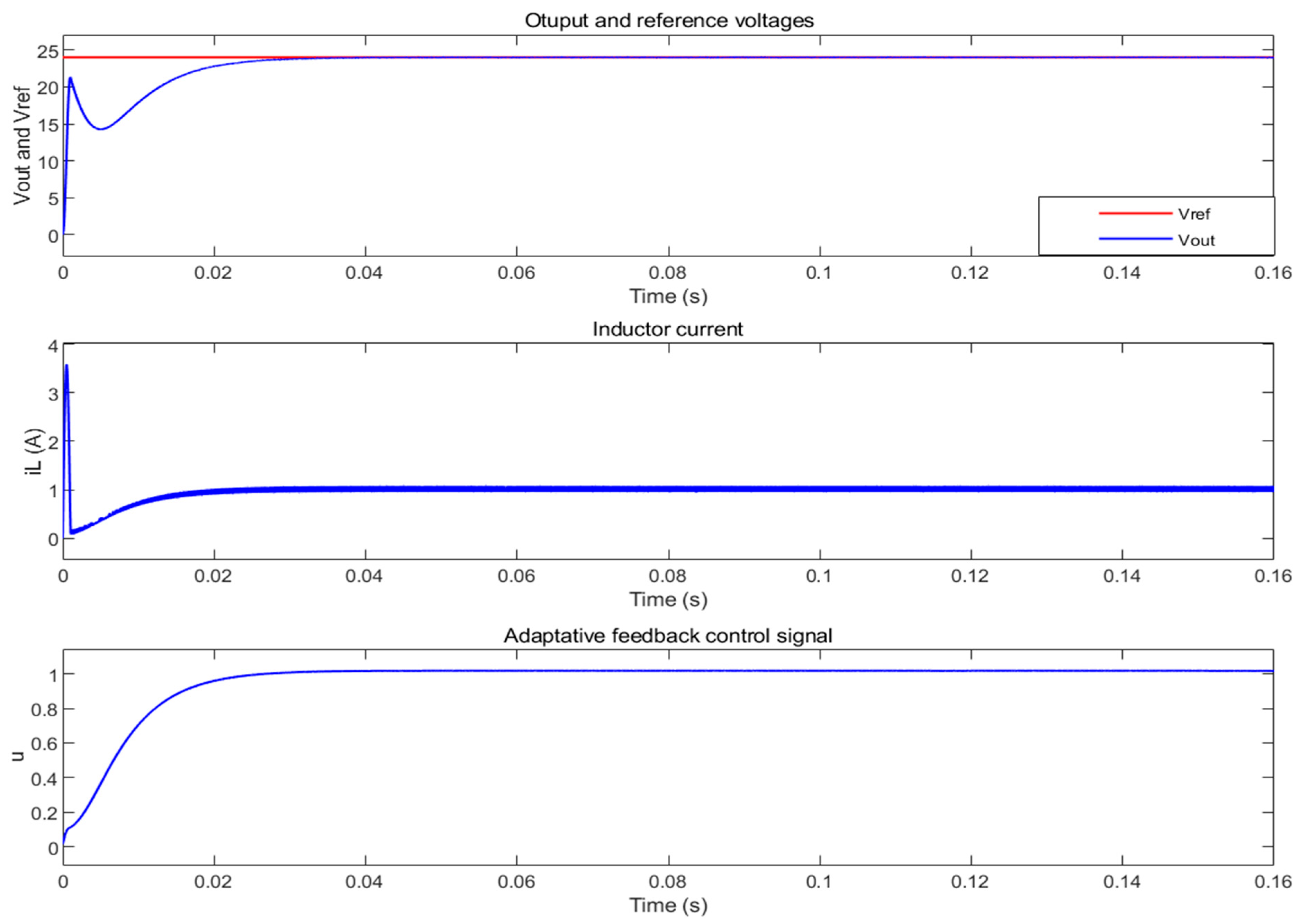
In the first case, the reference voltage remains constant (Vcref = 24 V). This scenario is employed to elucidate the application of the proposed nonlinear adaptive feedback control strategy for the DC-DC boost converter.
Figure 4 displays the dynamic response waveforms of the system. Notably, the capacitor voltage stabilizes at the prescribed reference value of 24 V. The introduced control strategy effectively attains its control objective, upholding system stability, enhancing dynamic response speed, and fortifying resistance to interference.

5.2. Case 2

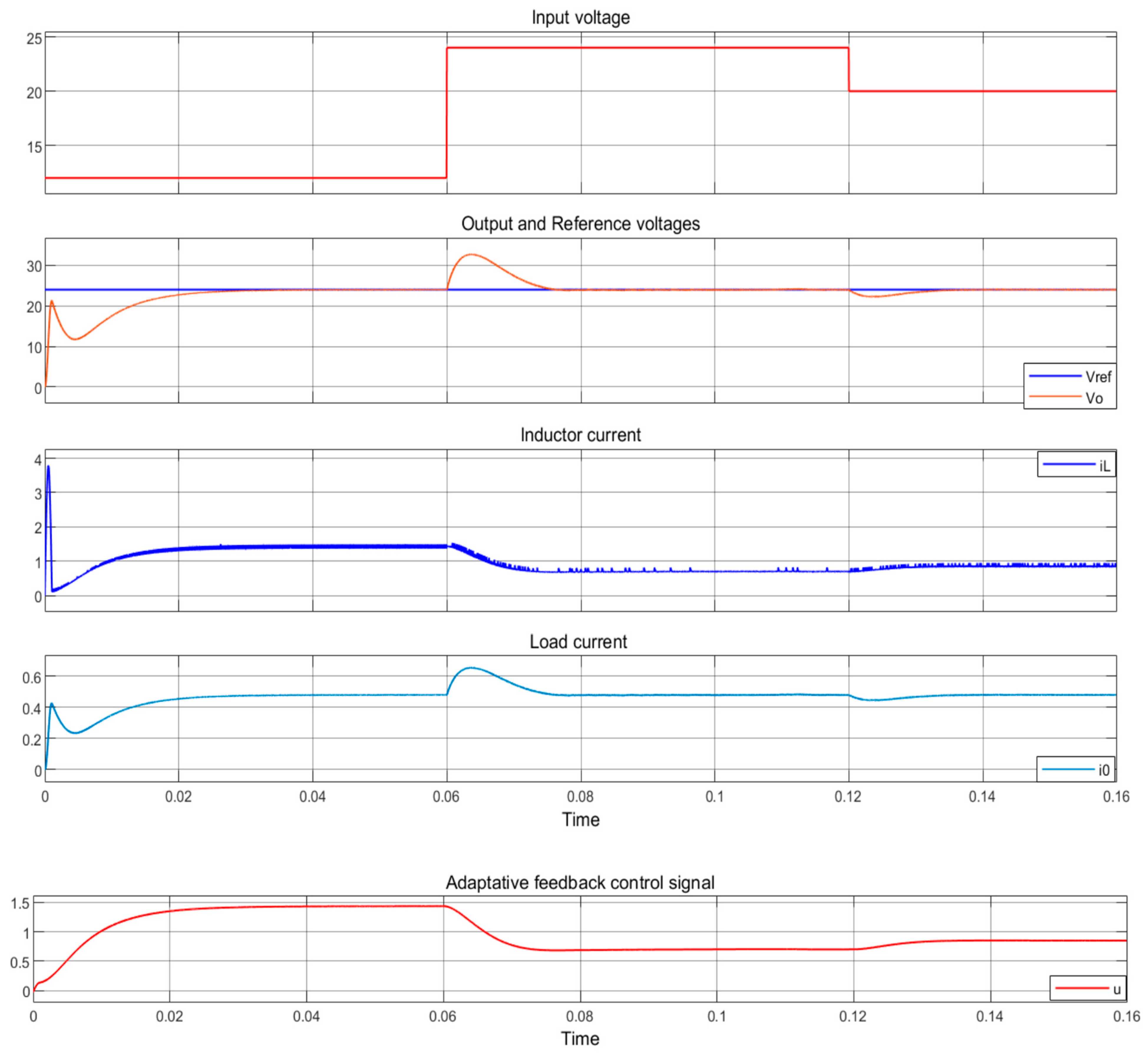
The second case assesses the effectiveness of the proposed controller strategy when subjected to abrupt changes in the input voltage.
In Figure 5, the dynamic response waveforms of the system depict the response to step changes in Vin, transitioning from 12 V to 24 V at 0.06 s and from 24 V to 20 V at 0.12 s. Notably, the DC bus voltage stabilizes precisely at the prescribed reference value of 24 V at the instant of the input voltage shift.
Upon close examination of Figure 5, it becomes evident that the adaptive feedback control strategy introduced exhibits a distinct absence of oscillations and showcases significantly reduced overshoot.

5.3. Case 3

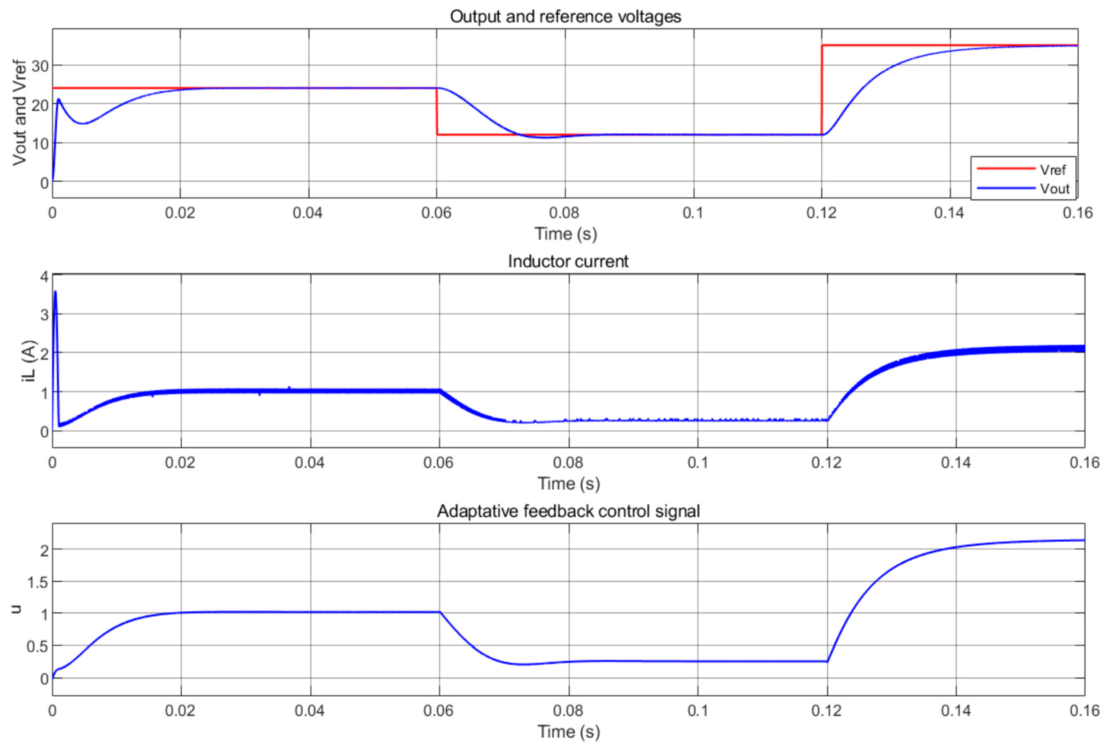
The third case examines the proficiency of the adaptive feedback controller in tracking a reference voltage that undergoes step changes. The reference voltage sequence includes a transition to 24 V in the initial 0.06 s, a subsequent increase to 12 V in the following 0.12 s, and then reverting to 34 V for the remaining duration.
As illustrated in Figure 6, the DC bus voltage stabilizes in line with the reference voltage alterations, as directed by the adaptive feedback control strategy. Remarkably, the proposed control approach achieves a swifter response rate and shorter adjustment time for the system. Consequently, it ensures heightened system stability and superior resistance to interference.

5.4. Case 4

In this case, we introduce step changes in the resistance as a variable of interest. Figure 7 provides a visual representation of the system’s dynamic response waveforms, where R initially stands at 50 Ω and then transitions to 100 Ω at 0.06 s. As depicted in Figure 7, the DC bus voltage is adeptly stabilized at the prescribed 24 V reference value through the employed adaptive control strategy. Furthermore, upon closer examination of Figure 7, it becomes evident that the adaptive parameters result in diminished overshoots for both the bus voltage and inductor current.
The simulation results substantiate the efficacy of the provided method and confirm that the boost converter can successfully control the boost converter with a CPL when it integrates the recommended output redefinition and control strategy.

6. Conclusions

In this research, we introduce a novel nonlinear adaptive feedback controller designed for the regulation of a boost converter operating within a DC microgrid with a constant power load. Our approach is rooted in the principles of exact feedback linearization and Lyapunov theory.
Upon examining the stability of the zero dynamics of the system, it becomes evident that controlling the direct capacitor voltage leads to unstable zero dynamics, rendering the system a nonminimum phase system. We delve into the analysis and simulation of the nonminimum phase characteristics of the boost converter across various scenarios, including input voltage variations, load resistance changes, and reference voltage adjustments.
In forthcoming research, we plan to conduct a comprehensive comparative analysis of the proposed control strategy and other existing controllers. This analysis will encompass aspects such as stability, tracking error, switching efficiency, harmonics reduction, current and voltage ripple, and more, all through a rigorous and systematic methodology.
Our proposed control method effectively addresses the limitations of exact feedback linearization, notably its reliance on precise mathematical models and its inapplicability to unstable zero-dynamic systems. Additionally, our approach successfully resolves the instability issue induced by constant power loads, ensuring the stability of the DC bus voltage.
It is worth noting that the nonlinear adaptive feedback control strategy introduced in this study has the potential for broader applicability to other converters with constant power loads, including DC-DC buck boost converters.

Author Contributions

Conceptualization, K.J.; methodology, K.J. and M.A.; software, M.C.; validation, K.J., M.C. and M.A.; formal analysis, K.J.; investigation, K.J.; resources, K.J.; data curation, K.J.; writing—original draft preparation, M.A.; writing—review and editing, M.C.; visualization, M.A.; supervision, K.J.; project administration, M.A.; funding acquisition, M.C. All authors have read and agreed to the published version of the manuscript.

Funding

This research was funded by the Deanship of Scientific Research at University of Business and Technology (UBT), Jeddah 21361, Saudi Arabia.

Data Availability Statement

Data are contained within the article.

Conflicts of Interest

The authors declare no conflict of interest.

References

  1. Rahimi, A.M.; Emadi, A. An analytical investigation of DC/DC power electronic converters with constant power loads in vehicular power systems. Trans. Veh. Technol. 2009, 58, 2689–2702. [Google Scholar] [CrossRef]
  2. Lu, X.; Sun, K.; Guerrero, J.M.; Vasquez, J.C.; Huang, L.; Wang, J. Stability enhancement based on virtual impedance for dc microgrids with constant power loads. IEEE Trans. Smart Grid 2015, 6, 2770–2783. [Google Scholar] [CrossRef]
  3. Chang, X.; Li, Y.; Li, X.; Chen, X. An active damping method based on a supercapacitor energy storage system to overcome the destabilizing effect of instantaneous constant power loads in DC microgrids. IEEE Trans. Energy Convers. 2017, 32, 36–47. [Google Scholar] [CrossRef]
  4. Khaligh, A.; Rahimi, A.M.; Emadi, A. Negative Impedance Stabilizing Pulse Adjustment Control Technique for DC/DC Converters Operating in Discontinuous Conduction Mode and Driving Constant Power Loads. IEEE Trans. Veh. Technol. 2007, 56, 2005–2016. [Google Scholar] [CrossRef]
  5. Zhang, X.; He, W.; Zhang, Y. An Adaptive Output Feedback Controller for Boost Converter. Electronics 2022, 11, 905–914. [Google Scholar] [CrossRef]
  6. Cespedes, M.; Xing, L.; Sun, J. Constant power load system stabilization by passive damping. IEEE Trans. Power Electron. 2011, 26, 1832–1836. [Google Scholar] [CrossRef]
  7. Jouili, K.; Madani, A. Nonlinear Lyapunov control of a photovoltaic water pumping system. Energies 2023, 16, 2241. [Google Scholar] [CrossRef]
  8. Jouili, K.; Belhadj, W. Robust stabilization for uncertain non-minimum phase switched nonlinear System under arbitrary switchings. Symmetry 2023, 15, 596. [Google Scholar] [CrossRef]
  9. Rahimi, A.; Emadi, A. Discontinuous-Conduction Mode DC/DC Converters Feeding Constant-Power Loads. IEEE Trans. Ind. Electron. 2010, 57, 1318–1329. [Google Scholar] [CrossRef]
  10. Kwasinski, A.; Krein, P.T. Stabilization of constant power loads in dc-dc converters using passivity-based control. In Proceedings of the INTELEC 07–29th International Telecommunications Energy Conference, Rome, Italy, 30 September–4 October 2007; pp. 867–874. [Google Scholar]
  11. Zeng, J.; Zhang, Z.; Qiao, W. An interconnection and damping assignment passivity-based controller for a dc-dc boost converter with a constant power load. IEEE Trans. Ind. Appl. 2014, 50, 2314–2322. [Google Scholar] [CrossRef]
  12. Kwasinski, A. Dynamic behavior and stabilization of dc microgrids with instantaneous constant-power loads. IEEE Trans. Power Electron. 2011, 26, 822–834. [Google Scholar] [CrossRef]
  13. Villarroel, F.A.; Espinoza, J.R.; Pérez, M.A.; Ramírez, R.O.; Baier, C.R.; Sbárbaro, D.; Silva, J.J.; Reyes, M.A. Stable Shortest Horizon FCS-MPC Output Voltage Control in Non-Minimum Phase Boost-Type Converters Based on Input-State Linearization. IEEE Trans. Energy Convers. 2021, 36, 1378–1390. [Google Scholar] [CrossRef]
  14. Byrnes, C.; Isidori, A.; Willems, J. Passivity, feedback equivalence, and the global stabilization of minimum phase nonlinearsystems. IEEE Trans. Autom. Control 1991, 36, 1228–1240. [Google Scholar] [CrossRef]
  15. Singh, S.; Gautam, A.R.; Fulwani, D. Constant power loads and their effects in DC distributed power systems: A review. Renew. Sustain. Energy Rev. 2017, 72, 407–421. [Google Scholar] [CrossRef]
  16. Li, Y.; Vannorsdel, K.R.; Zirger, A.J.; Norris, M.; Maksimovic, D. Current mode control for boost converters with constant power loads. IEEE Trans. Circuits Syst. 2012, 59, 198–206. [Google Scholar] [CrossRef]
  17. Santi, E.; Li, D.; Monti, A.; Stankovic, A.M. A geometric approach to large-signal stability of switching converters under sliding mode control and synergetic control. In Proceedings of the Power Electronics Specialists Conference, Recife, Barazil, 16 June 2005; pp. 1389–1395. [Google Scholar]
  18. Jouili, K. Robuststabilization of non-minimum phase switched nonlinear systems with uncertainty. J. Syst. Sci. Complex. 2020, 33, 289–311. [Google Scholar]
  19. Zengshi, C.; Wenzhong, G.; Jiangang, H.; Xiao, Y. Closed-Loop Analysis and Cascade Control of a Nonminimum Phase Boost Converter. IEEE Trans. Power Electron. 2011, 26, 1237–1252. [Google Scholar]
  20. Mahmoudi, H.; Aleenejad, M.; Ahmadi, R. A new modulated model predictive control method for mitigation of effects of constant power loads. In Proceedings of the IEEE Power and Energy Conference at Illinois, Urbana, IL, USA, 19–20 February 2016; pp. 1–5. [Google Scholar]
  21. Emadi, A.; Khaligh, A.; Rivetta, C.; Williamson, G. Constant power loads and negative impedance instability in automotive systems:definition, modeling, stability, and control of power electronic converters and motor drives. IEEE Trans. Veh. Technol. 2006, 55, 1112–1125. [Google Scholar] [CrossRef]
  22. Zhao, Y.; Qiao, W.; Ha, D. A sliding-mode duty-ratio controller for dc/dc buck converters with constant power loads. IEEE Trans. Ind. Appl. 2014, 50, 1448–1458. [Google Scholar] [CrossRef]
  23. Baev, S.; Sheessel, Y. Causal output tracking in nonminimum phase boost DC/DC converter using sliding mode techniques. In Proceedings of the 2009 American Control Conference, St. Louis, MO, USA, 10–12 June 2009; pp. 77–82. [Google Scholar]
  24. Talebi, H.A.; Patel, R.V.; Khorasani, K. Control of Flexible-Link Manipulators Using Neural Networks; Springer Science & Business Media: Berlin/Heidelberg, Germany, 2001; p. 261. [Google Scholar]
  25. Sira-Ramirez, H.; Ortega, R. Passivity-basedcontrollers for the stabilization of dc-to-dc power converters, Decision and Control. In Proceedings of the 1995 34th IEEE Conference on Decision and Control, New Orleans, LA, USA, 13–15 December 1995; Volume 4, pp. 3471–3476. [Google Scholar]
  26. Escobar, G.; Ortega, R.; Sira-Ramirez, H.; Vilain, J.; Zein, I. An experimental comparison of several nonlinear controllers for power converters. IEEE Control. Syst. Mag. 1999, 19, 66–82. [Google Scholar]
  27. Ortega, R.; Perez, J.A.L.; Nicklasson, P.J.; Sira-Ramirez, H. Passivity-Based Control of Euler-Lagrange Systems: Mechanical, Electrical and Electromechanical Applications; Springer Science & Business Media: Berlin/Heidelberg, Germany, 2013. [Google Scholar]
  28. Slotine, J.-J.E.; Li, W. Applied Nonlinear Control; Prentice Hall: Englewood Cliffs, NJ, USA, 1991. [Google Scholar]
  29. Roshan, Y.M.; Moallem, M. Control of nonminimum phase loadcurrent in a boost converterusing output redefinition. IEEE Trans. Power Electron. 2014, 29, 5054–5062. [Google Scholar] [CrossRef]
  30. Jouili, K.; Braiek, N.B. Controllers design for stabilization of non-minimum phase of switched nonlinear systems. JCEAI Control. Eng. Appl. Inform. J. 2019, 21, 21–30. [Google Scholar]
  31. Alam, Z.; Ghosh, S.K.; Alkhateeb, A.F.; Roy, T.K.; Islam, M.S.; Saha, S.; Hussain, M.A. Robust hybrid nonlinear control approach for stability enhancement of a constant power load DC-DC boost converter. Alex. Eng. J. 2023, 74, 535–545. [Google Scholar] [CrossRef]
  32. Rahimi, A.; Khalilgh, A.; Emadi, A. Sub-Harmonic Problem in Multi-Converter Vehicular Power Systems. In Proceedings of the 2006 IEEE Vehicle Power and Propulsion Conference, Windsor, UK, 6–8 September 2006. [Google Scholar]
  33. Antonio, M.; Licea, R. Polytopic Robust Stability for a Dual-Capacitor Boost Converter in Symmetric and Non-Symmetric Configurations. Symmetry 2022, 14, 2331–2339. [Google Scholar]
  34. Emadi, A.; Ehsani, M. Negative impedance stabilizing controls for pwm dc-dc converters using feedback linearization techniques, Collection of Technical Papers. In Proceedings of the 35th Intersociety Energy Conversion Engineering Conference and Exhibit, Las Vegas, NV, USA, 24–28 July 2000; Volume 1, pp. 613–620. [Google Scholar]
  35. Trujillo, S.C.; Candelo-Becerra, J.E.; Hoyos, F.E. Numerical Validation of a Boost Converter Controlled by a Quasi-Sliding Mode Control Technique with Bifurcation Diagrams. Symmetry 2022, 14, 694–709. [Google Scholar] [CrossRef]
  36. Zhou, J.; Hassan, M.A.; Zhang, J.; Hou, M.; Wu, S.; Xing, G.; Chi, S. Stabilization of Constant Power Loads in DC Microgrid Systems Using an Adaptive Continuous Control Set Model Predictive Control. Symmetry 2021, 13, 1112–1140. [Google Scholar] [CrossRef]
  37. Bhavani, S.; Sivaprakasam, A. Dual Mode Symmetrical Proportional Resonant Controlled Quadratic Boost Converter for PMSM-Drive. Symmetry 2023, 15, 147–166. [Google Scholar] [CrossRef]
  38. Jiarong, W.; Yimin, L. Adaptive Backstepping Sliding Mode Control for Boost Converter with Constant Power Load. IEEE Access 2019, 7, 50797–50807. [Google Scholar]
  39. Villarroel, F.A.; Espinoza, J.R.; Pérez, M.A.; Ramírez, R.O.; Baier, C.R.; Sbárbaro, D.; Silva, J.J.; Reyes, M.A. A Predictive Shortest-Horizon Voltage Control Algorithm for Non-Minimum Phase Three-Phase Rectifiers. IEEE Access 2022, 10, 107598–107615. [Google Scholar] [CrossRef]
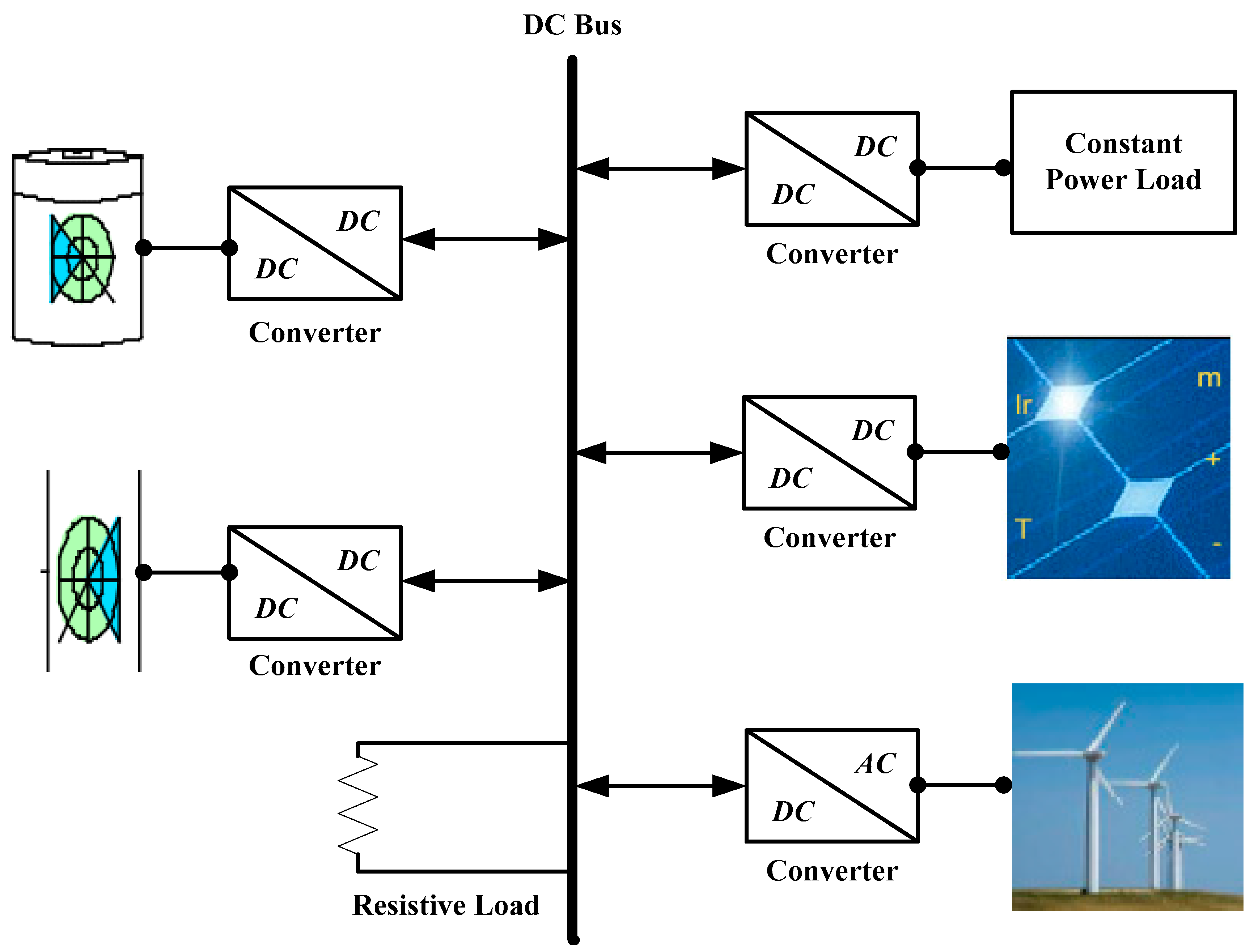
Figure 1. DC microgrid system configuration.
Symmetry 16 00352 g001
Figure 2. The DC distribution system in a simplified form with feeding a CPL.
Symmetry 16 00352 g002
Figure 3. Adaptive feedback control block diagram.
Symmetry 16 00352 g003
Figure 4. Output and reference voltages, inductor current, and the adaptative feedback control signal for Case 1.
Symmetry 16 00352 g004
Figure 5. Input voltage, output voltage, inductor current, load current, and the adaptative feedback control signal for Case 2.
Symmetry 16 00352 g005
Figure 6. Output voltage, inductor current, and the adaptative feedback control signal for Case 3.
Symmetry 16 00352 g006
Figure 7. Output voltage, inductor current, and the adaptative feedback control signal for Case 4.
Symmetry 16 00352 g007
Disclaimer/Publisher’s Note: The statements, opinions and data contained in all publications are solely those of the individual author(s) and contributor(s) and not of MDPI and/or the editor(s). MDPI and/or the editor(s) disclaim responsibility for any injury to people or property resulting from any ideas, methods, instructions or products referred to in the content.