
Comment on Lu et al. Ultrathin Terahertz Dual-Band Perfect Metamaterial Absorber Using Asymmetric Double-Split Rings Resonator. Symmetry 2018, 10, 293
Abstract
:1. Introduction and Background
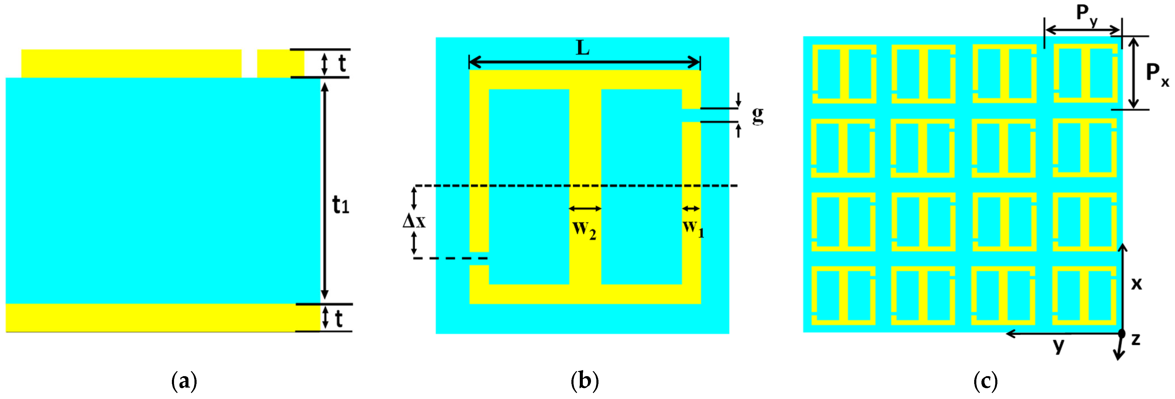
2. Design Details
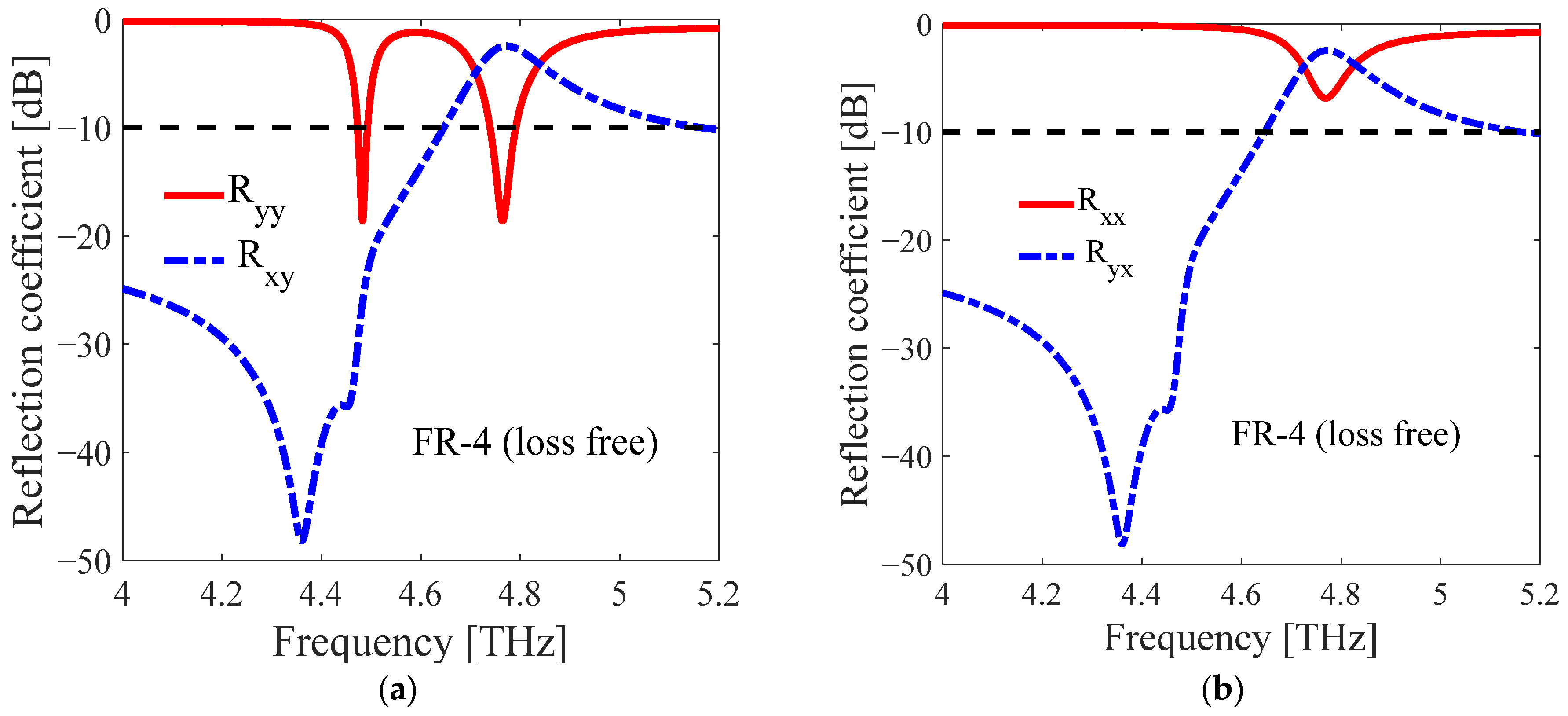
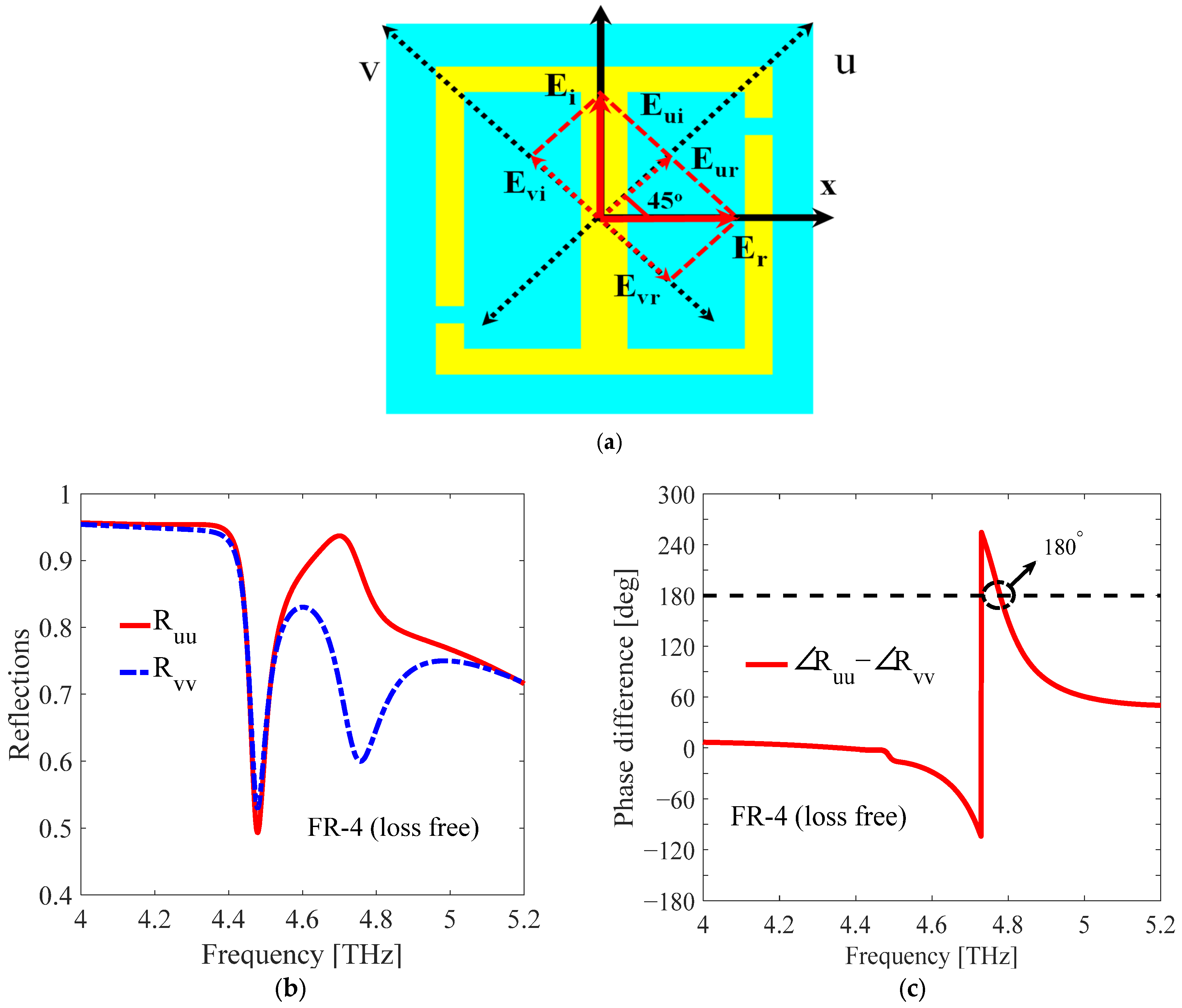
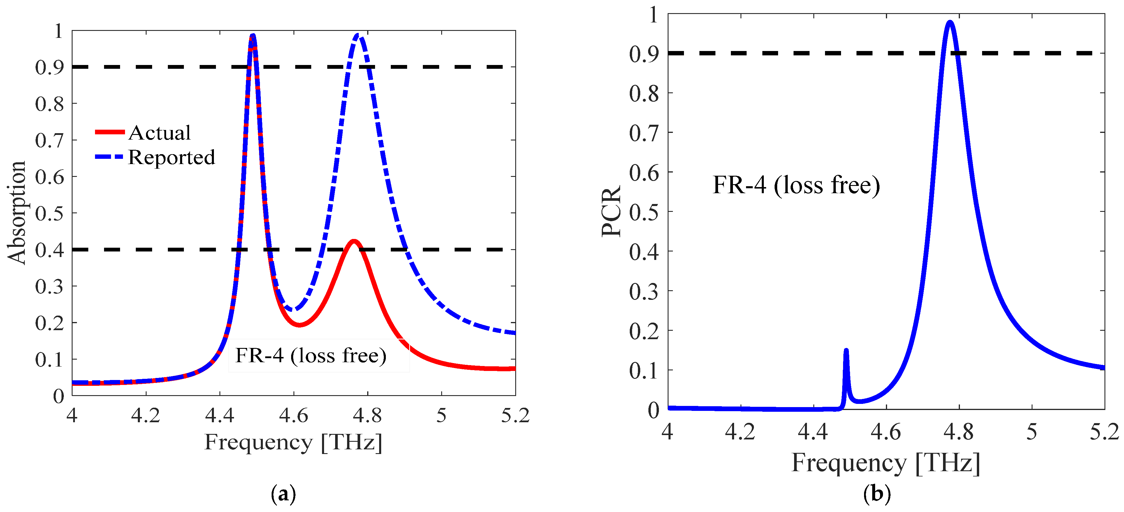
3. Results and Discussion
4. Conclusions
Conflicts of Interest
References
- Lu, T.; Zhang, D.; Qiu, P.; Lian, J.; Jing, M.; Yu, B.; Wen, J. Ultrathin terahertz dual-band perfect metamaterial absorber using asymmetric double-split rings resonator. Symmetry 2018, 10, 293. [Google Scholar] [CrossRef]
- Zhu, J.F.; Ma, Z.F.; Sun, W.J.; Ding, F.; He, Q.; Zhou, L.; Ma, Y.G. Ultra-broadband terahertz metamaterial absorber. Appl. Phys. Lett. 2014, 105, 021102. [Google Scholar] [CrossRef]
- Landy, N.I.; Sajuyigbe, S.; Mock, J.J.; Smith, D.R.; Padilla, W.J. Perfect metamaterial absorber. Phys. Rev. Lett. 2008, 100, 207402. [Google Scholar] [CrossRef] [PubMed]
- Sitara, B.; Rashid, A.; Tahir, F.A. A Multi-band Polarization Insensitive Metasurface Based Microwave Absorber Using Square and Circular Loop with Lumped Elements. In Proceedings of the 2021 1st International Conference on Microwave, Antennas & Circuits (ICMAC), Islamabad, Pakistan, 21–22 December 2021; pp. 1–4. [Google Scholar] [CrossRef]
- Lu, T.; Zhang, D.; Qiu, P.; Lian, J.; Jing, M.; Yu, B.; Wen, J.; Zhuang, S. Dual-band perfect metamaterial absorber based on an asymmetric H-shaped structure for terahertz waves. Materials 2018, 11, 2193. [Google Scholar] [CrossRef] [PubMed]
- Sood, D.; Tripathi, C.C. A wideband wide-angle ultra-thin metamaterial microwave absorber. Prog. Electromagn. Res. M 2018, 65, 135–136. [Google Scholar] [CrossRef]
- Wang, B.-Y.; Liu, S.-B.; Bian, B.-R.; Mao, Z.-W.; Liu, X.-C.; Ma, B.; Chen, L. A novel ultrathin and broadband microwave metamaterial absorber. J. Appl. Phys. 2014, 116. [Google Scholar] [CrossRef]
- Xiong, H.; Hong, J.S.; Luo, C.M.; Zhong, L.L. An ultrathin and broadband metamaterial absorber using multi-layer structures. J. Appl. Phys. 2013, 114, 064109. [Google Scholar] [CrossRef]
- Agrawal, A.; Misra, M.; Singh, A. Wide incidence angle and polarization insensitive dual broad-band metamaterial absorber based on concentric split and continuous rings resonator structure. Mater. Res. Epress 2018, 5, 9–12. [Google Scholar] [CrossRef]
- Ren, Y.H.; Ding, J.; Guo, C.J.; Qu, Y.; Song, Y.C. Design of a Quad-Band Wide-Angle Microwave Metamaterial Absorber. J. Electron. Mater. 2017, 46, 370–376. [Google Scholar] [CrossRef]
- Ahmed, F.; Ahmed, A.; Tamoor, T.; Hassan, T. Comment on Dual-Band Perfect Metamaterial. no. 2018. Materials 2019, 12, 3914. [Google Scholar] [CrossRef] [PubMed]
- Zafar, M.F.; Masud, U.; Rashid, A.; Murtaza, M.; Ullah, T. Comment on An ultrathin and broadband radar absorber using metamaterials. Waves Random Complex Media 2021, 32, 2872–2877. [Google Scholar] [CrossRef]
- Wahidi, M.S.; Mustafa, M.E.; Tahir, F.A. Comment on an ultrathin and broadband metamaterial absorber using multi-layer structures. [J. Appl. Phys. 114, 064109 (2013)]. J. Appl. Phys. 2019, 125, 166101. [Google Scholar] [CrossRef]
- Lakhtakia, A.; Bhattacharyya, S.; Ghosh, S.K. Comment on Wide incidence angle and polarization insensitive dual broad-band metamaterial absorber based on concentric split and continuous rings resonator structure. Mater. Res. Express 2019, 6, 9–12. [Google Scholar] [CrossRef]
- Kong, X.; Zhang, H.; Dao, R.; Liu, G. Comment on Design of a Quad-Band Wide-Angle Microwave Metamaterial Absorber. J. Electron. Mater. 2019, 48, 4166–4169. [Google Scholar] [CrossRef]
- Li, J.; Yuan, Y.; Yang, G.; Wu, Q.; Zhang, W.; Burokur, S.N.; Zhang, K. Hybrid Dispersion Engineering based on Chiral Metamirror. Laser Photonics Rev. 2023, 17, 2200777. [Google Scholar] [CrossRef]
- Yuan, Y.; Sun, S.; Chen, Y.; Zhang, K.; Ding, X.; Ratni, B.; Wu, Q.; Burokur, S.N.; Qiu, C.-W. A Fully Phase-Modulated Metasurface as An Energy-Controllable Circular Polarization Router. Adv. Sci. 2020, 7, 2001437. [Google Scholar] [CrossRef] [PubMed]


Disclaimer/Publisher’s Note: The statements, opinions and data contained in all publications are solely those of the individual author(s) and contributor(s) and not of MDPI and/or the editor(s). MDPI and/or the editor(s) disclaim responsibility for any injury to people or property resulting from any ideas, methods, instructions or products referred to in the content. |
© 2024 by the authors. Licensee MDPI, Basel, Switzerland. This article is an open access article distributed under the terms and conditions of the Creative Commons Attribution (CC BY) license (https://creativecommons.org/licenses/by/4.0/).
Share and Cite
Ullah, T.; Rashid, A. Comment on Lu et al. Ultrathin Terahertz Dual-Band Perfect Metamaterial Absorber Using Asymmetric Double-Split Rings Resonator. Symmetry 2018, 10, 293. Symmetry 2024, 16, 445. https://doi.org/10.3390/sym16040445
Ullah T, Rashid A. Comment on Lu et al. Ultrathin Terahertz Dual-Band Perfect Metamaterial Absorber Using Asymmetric Double-Split Rings Resonator. Symmetry 2018, 10, 293. Symmetry. 2024; 16(4):445. https://doi.org/10.3390/sym16040445
Chicago/Turabian StyleUllah, Tariq, and Aamir Rashid. 2024. "Comment on Lu et al. Ultrathin Terahertz Dual-Band Perfect Metamaterial Absorber Using Asymmetric Double-Split Rings Resonator. Symmetry 2018, 10, 293" Symmetry 16, no. 4: 445. https://doi.org/10.3390/sym16040445