Abstract
In this work, the vibration analysis of a layered, cylinder-shaped shell is undertaken. The structure of the shell layers is composed of functionally graded and isotropic materials. The vibrations of four-layered cylindrical shells with a ring support along the axial direction are investigated in this research. The two internal layers are composed of isotropic materials, and the external two layers are composed of functionally graded materials. The outer functionally graded material layers considered are stainless steel, zirconia, and nickel. The inner two isotropic layers considered are aluminum and stainless steel. The shell frequency equation is acquired by employing the Rayleigh–Ritz method under the shell theory of Sanders. The trigonometric volume fraction law is used to sort the functionally graded material composition of the FGM layers. The natural frequencies are attained under two boundary conditions, namely simply supported–simply supported and clamped–clamped.
MSC:
35A09; 35A35
1. Introduction
In the analysis of structures, a cylindrical shell is a major feature. Various mechanical facets of these shell structures are analyzed in addition to their potential implementation, one of which is shell vibration. In areas of technology such as liquid gases at high pressure, nuclear power stations, networks of pipes, and other marine and aircraft systems, the examination of such shells plays a crucial role. The biography for the past scientific work has been developed based on Love’s theory. Utilizing Sanders’ shell theory and the Ritz composition, many researchers [1,2,3,4,5,6,7,8] have analyzed the frequency of dimensionally stable cylindrical shells under ring support over many end situations. Zang et al. [9] described the study of a hypothesis in which, contrary to Love’s results, all strains disappear from any rigid body. It offered formulations for the stress effects and couples that satisfy the homogeneous equilibrium conditions based on three stress frictions. The effect of the boundary conditions on the free vibrations for a multilayered cylindrical shell was investigated using the concept based on Love’s first theorem and the beam functions utilized for the Ritz as inertial structural features. There were nine boundary conditions taken into account, four of which had the same finishing criterion as their starting criterion. The other five conditions had different end requirements. Zang et al. [10] created heat-resistant structures for space plane fusion reactors and airframes. Zhi et al. [11] compared the frequency parameters with a precise three-dimensional linear elasticity analysis to test the analysis. The vibrational analysis of the functionally graded materials (FGMs) also discussed the behavior of natural frequencies.
Iqbal et al. [12] discussed the vibrational analysis of cylindrical shells and natural frequencies (NFs) under different boundary conditions and investigated new precise programs for the motions of the circular cylindrical shell with intermediate ring support based on the Goldenviezer–Novozhilov shell principle. The analytical method investigated the vibrational behavior of the ring support cylinder, while the state-space technique was used to operate the homogeneous comparative methodology for the shell component, and the domain decomposition technique was investigated for the continuity criteria among shell parts in the sense of the previously described method. Iqbal et al. [13] suggested 3D anisotropic elasticity fundamental equations, from which time visibility with differential equations is constructed in a coherent matrix form, and examined numerous techniques such as power law, sigmoid, and exponential FGMs, and we will focus on the numerical solution that was predominantly derived from the theoretical formulation and calculated using the MARC system. With reference to the effects of the application of P-FGM to S-FGM and E-FGM, Li et al. [14] introduced four sets of in-plane boundary conditions for the strictly assisted FG cylindrical shell for which the free vibration analysis was conducted. Sofiyev et al. [15] investigated physical properties that were thought to be temperature-dependent and eventually modified in the stress distribution of the shell. The results of the temperature increase were studied by specifying an approximate elevated temperature on the cylinder’s outer surface and the average temperature on the cylinder’s inner surface. The properties were temperature-dependent and gradually changed as the intensity of the shell increased.
By evaluating the elevated temperature, Arshad et al. [16] also mentioned the rising temperature effect. The entire study examined the strength of cylindrical shells supported on Winkler–Pasternak frameworks and made of ceramic, FGM, and metal layers that were exposed to an axial load. The revised stability and durability equations of the Donnell form on the Pasternak base were gathered. Galerkin’s process analysis values were obtained for the critical axial load of three-layered cylindrical shells with and without an elastic foundation. Extensive parametric experiments were performed to investigate the effects of FGM sheet thickness differences on the radius-to-thickness ratio. Naeem et al. [17] studied the vibration properties of two-layered cylindrical shells made of isotropic material on a single layer and functionally graded material on another. A bi-layered cylindrical shell’s vibration frequency analysis consisting of two distinct functionally graded layers is proposed by Arshad et al. [18]. The thicknesses of the shell’s layers are considered to be constant and equivalent. It is anticipated that the components of the material of the bi-layered dynamically graded cylindrical shell will differ seamlessly.
Ghamkhar et al. [19] investigated the vibration analysis of a three-layered cylindrical shell, with the anterior and posterior layers made of mechanically graded materials and the buffer part made of isotropic material. Love’s thin shell theorem was applied to the relationships of strain vs. displacement and curvature vs. displacement. To manipulate the intensity formulas, the Rayleigh–Ritz method (RRM) was used to grow the computational Lagrangian to be expressed as an eigenvalue query. The frequency wavelengths for long, simple-assisted end states were calculated by altering the thickness-to-radius and length-to-radius ratios; two non-dimensional geometrical parameters; and small, dense, and thin CSs. Ghamkhar et al. [20] examined a three-layered FGM cylindrical shell’s vibration frequency with an FGM central layer and homogeneous material as the interior and posterior layers. The relationships between the strain and the stress were drawn from the shell theory of Sanders. By utilizing the RRM, the shell frequency result was derived. The effect of natural frequencies (NFs) was evaluated for different middle-layer thicknesses. The beam functions of the features were used to approximate the axial modal dependency. The fundamental natural frequency of a cylindrical shell against the time span and thickness-to-radius percentage in a broad range was reported and investigated through this research.
Liu et al. [21] focused on determining the axial buckling load of stiffened multilayer cylindrical shell panels made of functionally graded graphene-reinforced composites (FG-GPL RCs). They used rings and stringers as stiffening tools. The study utilized Halpin–Tsai relations for elastic properties and implemented the virtual work principle and finite element approach based on the first-order shear deformation theory and Lekhnitskii’s smeared stiffener approach to derive stability equations. It examined four nanofiller dispersion types (FG-X, FG-A, FG-O, and UD) and systematically investigated the effects of geometric and material parameters on buckling loads and mode shapes, providing valuable design insights. The present research investigates the vibrations of four-layered cylindrical shells with ring support along the axial direction. The shell layers consist of a combination of functionally graded and isotropic materials. Specifically, the two internal layers are made of isotropic materials, while the two external layers are composed of functionally graded materials. The outer layers are assumed to be made of stainless steel, zirconia, and nickel, whereas the inner isotropic layers are composed of aluminum and stainless steel. The shell frequency equation is derived using the Rayleigh–Ritz method based on Sander’s shell theory. It utilizes energy principles (strain energy and kinetic energy) to derive the governing equations in an approximate form. The resulting system of algebraic equations is solved as an eigenvalue problem to determine natural frequencies and mode shapes.
2. Materials and Methods
A coordinate mechanism of cylinders is represented as the shell of the center reference surface with x, θ, and z as the axial, angular, and thickness coordinates, respectively, where , , and denote the deformations of the displacement functions in the longitudinal, tangential, and transverse instructions accordingly (see Figure 1).
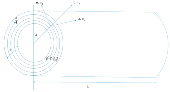
Figure 1.
Structure of CS with a ring support that is located along the length.
The strain energy relation is given below
where
The matrix [C] is represented as follows:
where express the strains that consist of the reference surface, indicate the curvatures, and ,, and (i, j = 1, 2, 6) represent the extensional, coupling, and bending stiffness [5] (Loy et al. 1999).
They are defined by the following formulas:
The reduced stiffness for isotropic materials is stated as,
And
The matrix is for isotropic circular-shaped CS, and is for FG CS; considering its structure and the characteristics of its constituents, the expressions from (2) and (3) in (1), , are rewritten as:
The expressions that follow are extracted from [19,20] and written as follows:
By substituting expressions (7) and (8) into Equation (6), expression (6) becomes as follows:
Shell kinetic energy is stated as
where
where is the mass density.
The Lagrange energy functional for a CS is described as follows as a function of the strain and kinetic energies:
Numerical Procedure
The RR method controls the normal frequencies of CS. The distortion defects in the longitudinal , transverse , and angular directions are taken into account. The displacement domains are now assumed by the following relationships:
And
where , and reflect the vibrational amplitudes in the x, θ, and t direction accordingly; the axial and circumferential wave numbers of mode shapes are indicated by n and m; ω symbolizes the angular vibration frequency of the shell wave; and , and which indicates the axial function that satisfies the end point conditions. In the longitudinal direction at , ring support is present. Here and represent with and without a ring support, respectively. m is the circumferential wave number and ω is the angular vibration frequency. And n denotes the axial model dependence in the longitudinal, circumferential, and transverse directions, respectively.
- symbolizes the axial function that meets the geometric edge condition requirement and is defined as
represents the roots of some transcendental equations, parameters depend on the values of , and change with respect to the edge conditions.
The geometric boundary conditions, namely simply supported and clamped boundary conditions, can be expressed mathematically in terms of the characteristic beam function as follows:
Simply supported boundary conditions .
Clamped boundary conditions .
The following non-dimensional parameters are used to expand this problem.
Expression (13) alters the structure as follows:
The Lagrangian function is transformed by employing the principle of maximum energy.
Lagrangian energy functional is extremized with respect to vibrational amplitudes , and , as shown below:
The resulting relation is defined in the form of a matrix as
where
and are the stiffness and mass matrices corresponding to the cylindrical shell.
3. Classification of Material
In the current study, a CS is taken into consideration, which is made up of four layers: isotropic material is used to construct the internal layers, while nickel, zirconia, and stainless steel are used to construct the outermost layers(see Figure 2).

Figure 2.
Component materials of shell layers.
The two elements using the trigonometric volume fraction law (VFL) are as follows:
This relation fulfills the VFL, i.e., , where is the shell’s thickness and indicates the power law exponent. Every layer is assumed to be the same thickness . The material parameters are as follows: for nickel; for zirconia; for stainless steel; for aluminum; for stainless steel and zirconia. Then, the effective material quantities are as follows:
For the expression above at
and
, respectively.
The stiffness moduli are altered as follows:
where and iso signify the two internal isotropic layers, and FGM symbolizes the two outer FGM layers.
4. Results and Discussion
To explain the accuracy and knowledge of the exact outcome, the current outcome is used by FGM and isotropic CS for SS edge conditions. RRM is used to achieve the current result. Table 1 represents the comparison of frequency parameters for simply supported isotropic cylindrical shells (n = 1, L = 20, R = 1, H = 0.01, and λ = 0.3) with those in [4]. Three materials are used to make two types of FG materials known as FGM cylindrical layers: stainless steel, zirconia, and nickel. Two FGM variations for the form of substance are found. Table 2 represents the material distribution.

Table 1.
Comparison of frequency parameters for simply supported isotropic cylindrical shell (n = 1, L = 20, R = 1, H = 0.01, and λ = 0.3).
Table 2.
Configurations of shell types.
- Type 1:
In type 1 FGM CS, inner surfaces are made of nickel and zirconia; on the other hand, outer layers are composed of stainless steel and zirconia.
- Type 2:
In type 2 FGM CS, inner surfaces are made with zirconia and nickel, and the outer layers are composed of zirconia and stainless steel.
In Table 3, the variation in natural frequencies (NFs) is presented under SS to SS edge conditions observed with (n = 1, R = 1, d = 0.01, H = 0.002, and L = 20). As the value of circumferential wave number m increases from 1 to 10, the value of NFs decreases. For power law exponent ranging from N = 1 to N = 9, the values of NFs also decrease, but slowly. For values ranging from N = 1 to 20, the values change from 366.3000 to 363.0547.
Table 3.
Vibration of NFs (Hz) against n for FGM CS under SS-SS boundary conditions when (n = 1, L = 20, H = 0.02, R = 1, and d = 0.1).
In Table 4, the variation in NFs for length-to-radius ratios is presented against the circumference wave number m for shell I with parameters (n = 2, R = 1, d = 0.01, H = 0.002, and L = 20) under the S-S Edge condition. As the value of m increases from 1 to 10, the values of NFs change, and for N = 1 to 11, the values of NFs change from 362.6197 to 359.2090.
Table 4.
Vibration of NFs (Hz) against n for FGM CS under SS-SS boundary conditions when (n = 2, L = 20, H = 0.02, R = 1, and d = 0.1).
In Table 5, the variation is the same as in Table 3 with parameters (n = 3, R = 1, d = 0.03, H = 0.002, and L = 90).
Table 5.
Behavior of NFs (Hz) against n for FGM CS under SS-SS boundary conditions when (n = 1, L = 20, N = 1, R = 1, and d = 0.4).
Table 6 represents the variation in NFs for length-to-radius ratios against m for shell I with parameters (n = 4, R = 1, d = 0.04, H = 0.02, and L = 20) under the S-S Edge condition. NFs increase up to 10. The value of NFs decreases from 4755.773 to 4575.089.
Table 6.
Behavior of NFs (Hz) when (n = 1, L = 20, N = 5, R = 1, and d = 0.5).
Configurations of shells:
The composition of the four-layered cylindrical shell made by FGM and the isotropic type of material is defined below in Table 2.
Table 7 describes the variation in NFs for length-to-radius ratios against m for shell I with parameters (n = 1, d = 0.4, R = 1, N = 5, and L = 20) under the S-S edge condition, and it was observed that NFs change from 4493.442 to 798.6292 for m.
Table 7.
Behavior of NFs (Hz) against n for FGM cylindrical shell when (n = 4, H = 0.005, N = 1, R = 1, and d = 1).
Table 8 presents the variation in NFs for length-to-radius ratios against m for the shell I with parameters (n = 1, R = 1, N = 5, and L = 20). It was observed and noted that the values of NFs change from 4313.561 to 792.0536 for m = 1 to m = 10. And for exponential law H = 0.001 to H = 0.07, the values change from 4313.561 to 4314.682.
Table 8.
Variation in NFs (Hz) against n for FGM cylindrical shell under the SS-SS boundary condition (n = 1, R = 1, H = 0.002, L = 20, and d = 0.1).
Table 9 shows the variation in NFs for length-to-radius ratios against m for the shell I with parameters (n = 1, R = 1, N = 10, d = 0.06, and L = 20) under the S-S Edge condition, and it is noted that NFs vary from 4280.537 to 4280.562.
Table 9.
Variation in NFs (Hz) against n for FGM cylindrical shell under SS-SS when (n = 2, R = 1, H = 0.002, L = 20, and d = 0.2).
Table 10 shows NFs for length-to-radius ratios against m for shell I with parameters (n = 1, R = 1, d = 0.7, N = 20, and L = 20). It is observed that its variation for m = 1 to m = 10 changes from 425.7616 to 425,7638. It has been noticed that a very small change occurs throughout the region.
Table 10.
Variation in NFs (Hz) against n for FGM cylindrical shell under the SS-SS boundary condition (N = 1, R = 1, n = 1, H = 0.005, and d = 0.8).
Table 11 shows NFs for length-to-radius ratios against circumference wave number n for shell I with parameters (n = 1, R = 1, N = 1, H = 0.005, and d = 0.8) under the S-S Edge condition by changing the value of H. The value of NFs changes from 418.758 to 594.9993 as n increases from 1 to 10. As the thickness of the shell varies, NFs remain nearly the same for different thicknesses from 0.001 to 0.07. It is noticed that for small changes in thickness, the values of NFs remain the same. Another noticeable variation for L is that the value of NFs increases when the range is from L = 10 to L = 70, increasing from 418.758 to 439.2311, indicating an increase in the frequency value.
Table 11.
Variation in NFs (Hz) against n for FGM CS under SS-SS boundary condition (N = 10, R = 1, n = 1, H = 0.005, and d = 0.9).
Figure 3 represents the variation in natural frequencies against circumferential wave number m for type 1 shell. The lower line shows the behavior of NFs for N = 1 and the upper line presents the behavior of NFs for N = 2. Natural frequencies increased swiftly from m = 1 to 2 and then increased slowly. Figure 4 represents the same for N = 1 and N = 3 under simply supported end point conditions for type 2 shell.
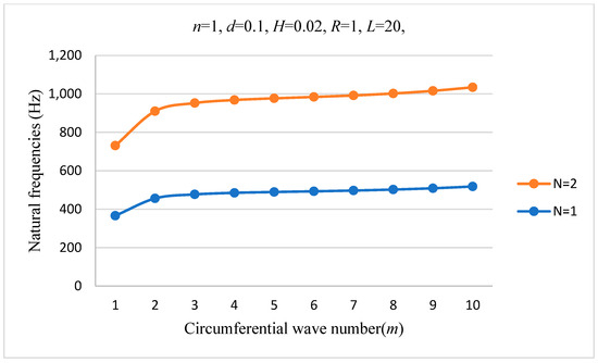
Figure 3.
Variation in NFs against m of type 1 SS-SS four-layer CS (n = 1, d = 0.1, H = 0.002, R = 1, and L = 20).

Figure 4.
Variation in NFs against m of type 2 SS-SS four-layer CS (n = 2, d = 0.1, H = 0.002, R = 1, L = 20).
Figure 5 presents the behavior of NFs against m for type 1 four-layered cylinder-shaped shell. The natural frequencies are obtained under simply supported edge conditions. Natural frequencies rapidly decreased from m = 1 to 2 and then slowly increased for m = 3, after which they behaved smoothly. The results are acquired for thicknesses 0.001 and 0.005 of type 1 shell. In Figure 6, the same behavior of NFs is observed for thicknesses 0.001, 0.005, and 0.007 of type 2 shell.
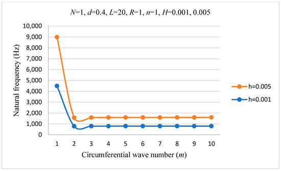
Figure 5.
Variation in NFs against m of type 1 SS-SS four-layer CS (n = 1, d = 0.4, N = 1, R = 1, L = 20, and H = 0.001, 0.005).

Figure 6.
Variation in NFs against m of type 2 SS-SS four-layer CS (n = 1, d = 0.5, N = 5, R = 1, L = 20, and H = 0.001, 0.005, and 0.007).
Figure 7 represents the variation in NFs against m of type 2 SS-SS four-layer CS with n = 2, d = 0.9, N = 1, R = 1, and H = 0.005. It is noticed that NFs are very close for L = 10, 20, and 40. The results increased rapidly from m = 1 to 2 and then increased slowly with increasing m.

Figure 7.
Variation in NFs against m of type 2 SS-SS four-layer CS (n = 2, d = 0.9, N = 1, R = 1, and H = 0.005).
Figure 8 shows the vibrations of NFs (Hz) for a four-layered clamped–simply supported circular cylinder-shaped shell against the position of the ring support with different H/R ratios .

Figure 8.
Vibrations of NFs (Hz) for a three-layered free circular cylinder-shaped shell against the position of the ring support with different H/R ratios .
Figure 8 describes the vibrations of NFs (Hz) for a four-layered free circular cylinder-shaped shell against the position of the ring support with different H/R ratios . The extreme lower line is obtained for H/R = 0.001, the extreme upper line is obtained for H/R = 0.01, and the middle line represents H/R = 0.05. It is clearly seen that NFs behave symmetrically as they increase from d = 0 to 0.5, attain their maximum value at d = 0.5, and then decrease from d = 0.05 to d = 1.
5. Discussion
The study presented in this work delves into the intricate vibration behavior and natural frequencies of layered cylindrical structures composed of functionally graded and isotropic materials. By investigating the vibrations of four-layered cylindrical shells assisted by a ring over their length, this research aims to uncover valuable insights into the dynamics of such composite structures. One of the distinctive features of this study is the composition of the layered cylindrical shells. The internal two layers are constructed by using isotropic materials, specifically aluminum and stainless steel, while the external two layers consist of functionally graded materials (FGM), namely stainless steel, zirconia, and nickel. This combination offers a diverse range of mechanical properties, making it an intriguing subject for exploration. The research involves a cylindrical shell with each of its four layers having an equal thickness, denoted as h/4.
To effectively analyze the vibration behavior and natural frequencies of these layered cylindrical shells, the Rayleigh–Ritz method (RRM) is employed within the framework of Sander’s shell theory. This method allows for the derivation of the shell frequency equation, providing valuable insights into the system’s dynamic response. Furthermore, the research investigates the natural frequencies of the shells under two distinct boundary conditions: simply supported–simply supported (SS-SS) and clamped–clamped (C-C). By exploring these boundary conditions, the study aims to provide a thorough understanding of how different support configurations impact the vibrational characteristics of the cylindrical shells.
In summary, this research contributes significantly to the understanding of vibration behavior and natural frequencies in layered cylindrical structures composed of functionally graded and isotropic materials. By leveraging advanced analytical techniques and exploring various material compositions and boundary conditions, the study sheds light on the complex dynamics of such composite systems, with potential implications for a wide range of engineering applications.
6. Conclusions
The current study was conducted to check the vibration characteristics of thin circular CS formed from FGM. The FG cylindrical shell constituents are made of stainless steel, nickel, zirconia, and aluminum. These four types were studied by changing the configuration of the layers of FG material. These constituents in type 1 of the cylindrical shells vary across the shell’s thickness constantly, seamlessly, and steadily from the FG layer’s inner to its outermost layer. The basic objectives were to obtain shell frequency equations with the help of these theories and techniques. Sander’s shell theory was applied to solve the shell frequency equations based on Kirchhoff’s assumptions. RRM was used to solve the shell vibration problems by utilizing the Lagrangian energy relation to obtain the shell’s frequency equation in numerical form. Axial modal dependence was approximated by trigonometric functions for simply supported end conditions and characteristic beam functions for number-clamped boundary conditions.
The study found that the minimum frequency occurs at specific wave numbers for all boundary conditions and is influenced directly by increasing the value of N, L, n, d, H, and L/R. The NFs decreased by varying N under different conditions. All the results were very close to each other. This analysis may be extended for the study of different shell problems, such as changing parameters like the thickness or length of the shell and the position of the ring. The frequency curves of the shell with ring support at different positions obtain symmetric shapes because of the same edge conditions. They are not symmetrical around the center because of different end point conditions. The induction of ring support on a cylinder-shaped shell has a significant effect on the NFs compared to the shell frequencies without ring support.
For the presented cylindrical shell, the results were obtained using MATLAB software version 2019 under simply supported–simply supported and clamped–clamped boundary conditions. These results illustrate the natural frequency behavior as a function of the circumferential wave number. Significant findings are as follows: The natural frequency increases as the power law index N″ increases. An increase in the length L″ of the shell leads to an increase in the natural frequency. Increasing the shell thickness h″ results in higher natural frequencies. Varying the ring support position along the longitudinal path shows that the natural frequency increases, reaching its maximum when the ring is at the central position of the shell, and then decreases as the ring position moves beyond the center.
These findings highlight the critical influence of geometric and material parameters on the vibrational behavior of cylindrical shells, providing insights for optimizing design and performance.
Author Contributions
Conceptualization, M.G. and N.H.; methodology, M.G., A.N.A.-K. and N.H.; validation, A.N.A.-K., M.G. and N.H.; writing draft, editing, M.G., A.N.A.-K. and N.H.; review, M.G., A.N.A.-K. and N.H.; funding, A.N.A.-K.; supervision, M.G. All authors have read and agreed to the published version of the manuscript.
Funding
This research received no external funding.
Data Availability Statement
Data are contained within the article.
Conflicts of Interest
The authors declare no conflicts of interest.
References
- Niino, M.; Hirai, T. Functionally gradient materials. In pursuit of super heat-resisting materials for spacecraft. J. Jpn. Soc. Compos. Mater. 1987, 13, 257–264. [Google Scholar]
- Lam, K.Y.; Loy, C.T. Effects of boundary conditions on frequencies of a multi-layered cylindrical shell. J. Sound Vib. 1995, 188, 363–384. [Google Scholar] [CrossRef]
- Swaddiwudhipong, S.; Tian, J. Vibrations of cylindrical shells with intermediate supports. J. Sound Vib. 1995, 187, 69–93. [Google Scholar] [CrossRef]
- Loy, C.T.; Lam, K.Y. Vibration of cylindrical shells with ring support. Int. J. Mech. Sci. 1997, 39, 455–471. [Google Scholar] [CrossRef]
- Loy, C.T.; Lam, K.Y. Vibration of functionally graded cylindrical shells. Int. J. Mech. Sci. 1999, 41, 309–324. [Google Scholar] [CrossRef]
- Pradhan, S.C.; Loy, C.T. Vibration characteristics of functionally graded cylindrical shells under various boundary conditions. Appl. Acoust. 2000, 61, 111–129. [Google Scholar] [CrossRef]
- Xiang, Y.; Ma, Y.F. Exact solutions for vibration of cylindrical shells with intermediate ring supports. Int. J. Mech. Sci. 2002, 44, 1907–1924. [Google Scholar] [CrossRef]
- Chen, W.Q.; Bian, Z.G. Three-dimensional vibration analysis of fluid-filled orthotropic FGM cylindrical shells. Int. J. Mech. Sci. 2004, 46, 159–171. [Google Scholar] [CrossRef]
- Zhang, L.; Xiang, Y. Vibration of open circular cylindrical shells with intermediate ring supports. Int. J. Solids Struct. 2006, 43, 3705–3722. [Google Scholar] [CrossRef]
- Zhang, L.; Xiang, Y. Local adaptive differential quadrature for free vibration analysis of cylindrical shells with various boundary conditions. Int. J. Mech. Sci. 2006, 48, 1126–1138. [Google Scholar] [CrossRef]
- Zhi-Yuan, C.; Hua-Ning, W. Free vibration of FGM cylindrical shells with holes under various boundary conditions. J. Sound Vib. 2007, 306, 227–237. [Google Scholar] [CrossRef]
- Iqbal, Z.; Naeem, M.N. Vibration characteristics of FGM circular cylindrical shells using wave propagation approach. Acta Mech. 2009, 208, 237–248. [Google Scholar] [CrossRef]
- Iqbal, Z.; Naeem, M.N. Vibration characteristics of FGM circular cylindrical shells filled with fluid using wave propagation approach. Appl. Math. Mech. 2009, 30, 1393–1404. [Google Scholar] [CrossRef]
- Li, S.R.; Fu, X.H. Free vibration of three-layer circular cylindrical shells with functionally graded middle layer. Mech. Res. Commun. 2010, 37, 577–580. [Google Scholar] [CrossRef]
- Sofiyev, A.H.; Avcar, M. The stability of cylindrical shells containing an FGM layer subjected to axial load on the Pasternak foundation. Engineering 2010, 2, 228. [Google Scholar] [CrossRef]
- Arshad, S.H.; Naeem, M.N. Vibration of bilayered cylindrical shells with layers of different materials. J. Mech. Sci. Technol. 2010, 24, 805–810. [Google Scholar] [CrossRef]
- Naeem, M.N.; Khan, A.G. Vibration of three-layered FGM cylindrical shells with a middle layer of isotropic material for various boundary conditions. World J. Mech. 2014, 4, 315–331. [Google Scholar] [CrossRef][Green Version]
- Arshad, S.H.; Naeem, M.N. Influence of ring support on free vibration of sandwich functionally graded cylindrical shells with a middle layer of isotropic material. J. Eng. Res. 2016, 4, 9. [Google Scholar] [CrossRef]
- Ghamkhar, M.; Naeem, M.N. Vibration frequency analysis of three-layered cylinder-shaped shell with the effect of FGM central layer thickness. Sci. Rep. 2019, 9, 1566. [Google Scholar] [CrossRef]
- Ghamkhar, M.; Naeem, M.N. Vibration analysis of a three-layered FGM cylindrical shell including the effect of ring support. Open Phys. 2019, 17, 587–600. [Google Scholar] [CrossRef]
- Liu, Z.; Tornabene, F.; Dimitri, R.; Babaei, M. Numerical Study of the Buckling Response of Stiffened FG Graphene-Reinforced Multilayer Composite Cylindrical Panels. Processes 2024, 12, 430. [Google Scholar] [CrossRef]


Disclaimer/Publisher’s Note: The statements, opinions and data contained in all publications are solely those of the individual author(s) and contributor(s) and not of MDPI and/or the editor(s). MDPI and/or the editor(s) disclaim responsibility for any injury to people or property resulting from any ideas, methods, instructions or products referred to in the content. |
© 2024 by the authors. Licensee MDPI, Basel, Switzerland. This article is an open access article distributed under the terms and conditions of the Creative Commons Attribution (CC BY) license (https://creativecommons.org/licenses/by/4.0/).