Article

The Aesthetics and Pragmatics of Symmetry in High-Gain and Wideband Circularly Polarized Antenna Design

School of Electronic Engineering and Intelligence, Dongguan University of Technology, Dongguan 523808, China
*
Author to whom correspondence should be addressed.
Symmetry 2024, 16(8), 1016; https://doi.org/10.3390/sym16081016
Submission received: 15 July 2024 / Revised: 2 August 2024 / Accepted: 5 August 2024 / Published: 9 August 2024

Abstract

:
In this study, a high-gain broadband circularly polarized crossed dipole antenna is designed. This antenna utilizes two pairs of cross dipoles and a pair of phase delay lines to form circularly polarized radiation. Open-circuit stubs are symmetrically loaded on the four arms of these dipole pairs to introduce new circularly polarized resonating frequencies. Additionally, a symmetrically positioned rectangular ring patch is introduced directly beneath the cross dipoles to generate the third circularly polarized resonating frequency, thereby enhancing the axial ratio bandwidth of the antenna symmetrically. Furthermore, metal posts are symmetrically loaded at the four right angles of the rectangular ring patch to augment the antenna gain, maintaining the overall symmetrical balance crucial for optimal circularly polarized radiation performance. This symmetric design ensures that the antenna achieves a 3dB axial ratio bandwidth of 29.2% (1.9–2.55 GHz) and sustains a gain of 7.5 dB within the passband, showcasing excellent circularly polarized radiation attributes.

1. Introduction

Circularly polarized antennas have advantages such as reducing polarization mismatch, resisting multipath interference, and suppressing the Faraday rotation effect. Therefore, circularly polarized antennas are widely used in various wireless communication systems, including global positioning systems (GPSs) [1], wireless local area networks (WLANs) [2,3,4], satellite communication systems [5,6], etc. With the development of modern wireless communication, improving the axial ratio bandwidth and gain of circularly polarized antennas has become an urgent problem to be solved.
Traditional methods for achieving circularly polarized radiation include corner truncation, surface slotting, and adding parasitic elements, but the axial ratio bandwidth of antennas designed by these methods generally does not exceed 5% [7,8,9]. In 2008, a new type of printed cross-dipole antenna proposed by Baik et al. received widespread attention [10]. This antenna uses a pair of printed three-quarter circular rings to create a 90° phase difference between two pairs of dipoles, forming a circular polarization frequency and achieving an axial ratio bandwidth of 15.6% (2.13–2.49 GHz). By changing the shape of the dipoles, these antennas achieved 27% (2.30–2.9 GHz), 26.4% (0.97–1.265 GHz), 25.3% ((2.16–2.78 GHz), and 23.2% (2.1–2.65 GHz) axial ratio bandwidths, respectively [11,12,13,14], and the average gains of these antennas were 6.8 dB, 8 dB, 7 dB, and 7.1 dB within the passband, respectively. By adding parasitic elements, the axial ratio bandwidth of these antennas reached 22.89% (2.52–3.17 GHz), with an average gain of 7.6 dB [15]. The antenna designed in [11] achieved a wide circularly polarized bandwidth, but the gain within the passband was 6.8 dB; the antennas designed in articles [12,13,14,15] achieved high gains but did not achieve wide circularly polarized bandwidths. In [16], the realization of wideband circularly polarized performance was achieved by feeding four vertically positioned linearly polarized dipole antenna elements through a phase-shifting feed network. Although an axial ratio bandwidth of 80.7% (1.7–4.0 GHz)) was attained, the in-band gain demonstrated significant variation, ranging from 1dB to 8 dB. A wideband circularly polarized cross-dipole antenna with a folded ground plane, discussed in [17], possessed an axial ratio bandwidth of 85.7% (1.3–3.25 GHz). However, the in-band gain was not stable and rapidly decreased to 3dB after 2.8 GHz. In [18], a truncated-corner patch antenna based on a substrate-integrated waveguide achieves circular polarization performance, with a stable gain of 6.5 dB (11.5–12 GHz) and an axial ratio bandwidth of 6.4%. The dual-fed wideband circular-polarized antenna (1.75–2.30 GHz), which operates on a common mode and differential mode as described in [19], exhibits an unstable in-band gain (ranging from −2–2 dB). An all-metal wideband circularly polarized single-patch antenna was introduced in [20]. This antenna boasts an axial ratio bandwidth of 6.4% (1.52–1.62 GHz) and an in-band gain ranging from 2 dB to 7 dB. However, the above antennas could not simultaneously achieve wide axial ratio bandwidth and high gain.
To simultaneously achieve wide axial ratio bandwidth and high gain, this paper proposes a high-gain broadband circularly polarized crossed dipole antenna. Utilizing two pairs of crossed dipoles and a pair of three-quarter circular rings forms the first circularly polarized resonating frequency. Subsequently, open-circuit stubs are loaded on the four arms of these two pairs of crossed dipoles to introduce new circularly polarized resonating frequency. Finally, a rectangular ring patch is printed on the substrate directly below the crossed dipoles to form the third circularly polarized resonating frequency, thereby broadening the axial ratio bandwidth of the antenna. It is worth noting that loading metal posts at the four right angles of the rectangular ring patch can increase the antenna gain. The results show that the antenna achieves a 3 dB axial ratio bandwidth of 29.2% (1.9–2.55 GHz) and maintains a gain of 7.5 dB within the passband, exhibiting good circularly polarized radiation performance.

2. Antenna Design

2.1. Antenna Configuration

The configuration of the proposed circularly polarized crossed dipole antenna is shown in Figure 1. This antenna consisted of three layers of dielectric substrates. A square ground plane ( S 1 × S 1 ) was printed on the back surface of the bottom layer ( tan δ = 0.02 , ε r = 4.4 ) with a height of h1. A rectangular metal ring patch ( W 4 , S 3 × S 3 ) was printed on the upper surface of the middle layer ( tan δ = 0.02 , ε r = 4.4 ) with a height of h3. In addition, four metal posts ( r 3 , h 3 + h 4 ) were loaded at the four right angles of the rectangular ring patch, forming a square cavity structure and then suppressing surface waves and improving the gain of the antenna. Meanwhile, two pairs of cross-dipole arms ( L 1 , W 1 , L 2 , W 2 , L 4 ) with open-circuit branches ( L 3 × W 3 ) were printed on both the upper and lower surfaces of the top layer ( tan δ = 0.0025 , ε r = 3.38 ) with a thickness of h 1 . Rogers substrates have the characteristics of low loss and high cost compared with FR4. Considering the cost and loss, the Rogers substrate was only used for printing the cross-dipole arm, rather than having all the substrates be FR4 or Rogers. The two pairs of cross-dipole arms were connected by the phase delay lines ( r 1 , r 2 ) to provide a 90° phase difference, achieving circular polarization radiation. Compared to existing broadband circular polarization cross dipole antennas, the proposed antenna extends the axial ratio bandwidth by loading branches on the folded cross-dipole arm and a rectangular ring patch directly below the dipole arm, effectively eliminating the antenna’s transverse size. Additionally, four metal posts were loaded to form a metal cavity, which enhanced the antenna’s directional radiation and improved its gain.

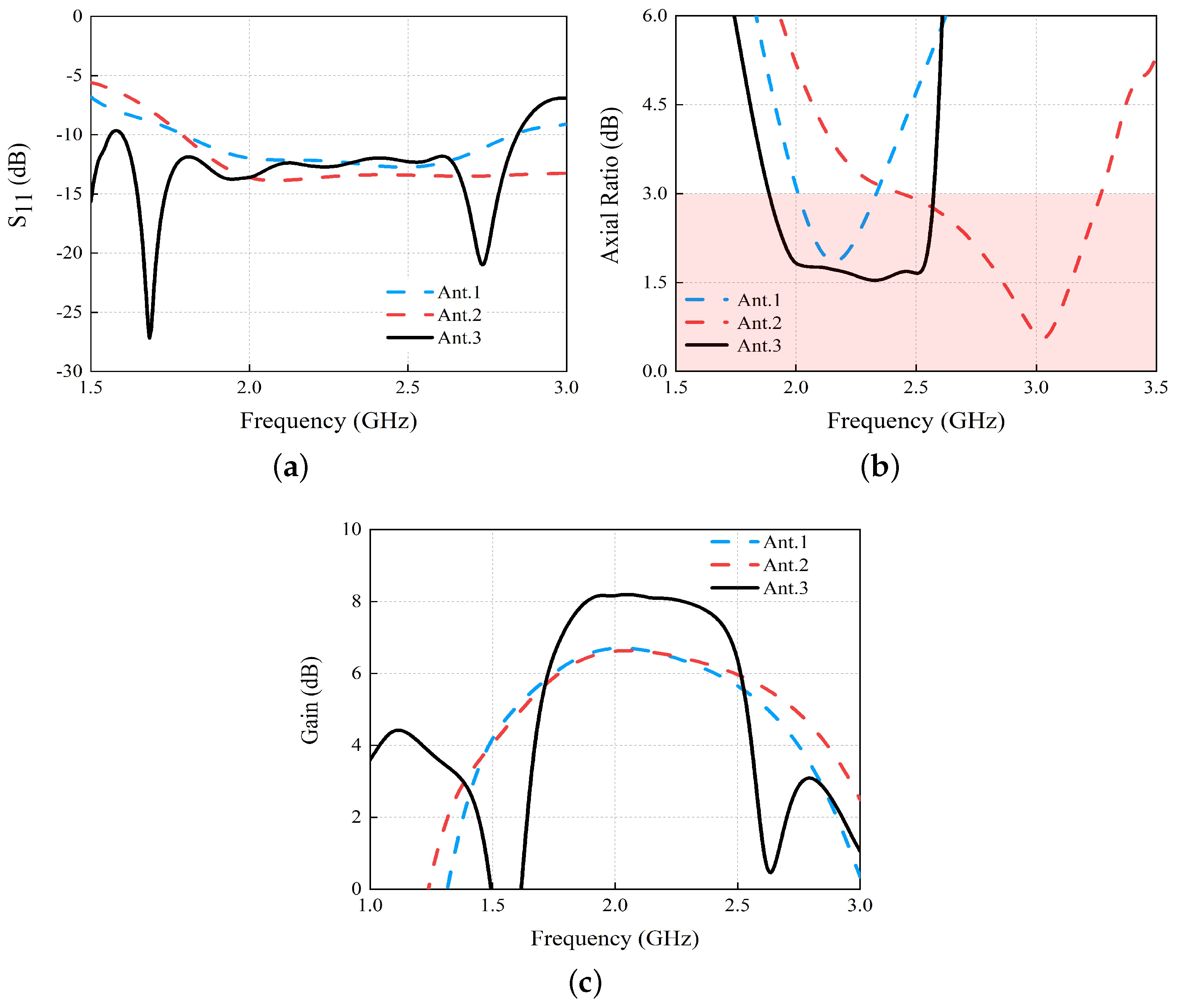
2.2. Step-by-Step Design Process

Figure 2 shows the design process of the antenna. Ant.I was designed based on traditional cross dipoles. In Ant.II, open-circuit branches were loaded on each dipole arm. In Ant.III, the dipole arm was improved to a windmill shape, and a dielectric substrate was added between the cross-dipole arms and the ground plane. A rectangular ring metal patch was printed on the upper surface of this dielectric substrate, with metal posts loaded at the four right angles of the rectangular ring metal patch.
To reveal the mechanism of the proposed antenna, the S 11 , AR, and gain results of Ant.I, Ant.II, and Ant.III are shown in Figure 3. It can be seen that the impedance bandwidth of Ant.I is 45.3% (1.79–2.84 GHz), and only a circularly polarized resonating frequency is produced. The 3dB axial ratio bandwidth is 14.7% (2.01–2.33 GHz). By loading open-circuit branches on each dipole arm in Ant.II, a new circularly polarized resonant frequency was introduced and the axial ratio bandwidth was broadened to 29% (2.44–3.27 GHz). The rectangular ring metal patch introduced in Ant.III also generated a circularly polarized resonant frequency and the axial ratio bandwidth is further improved to 30.5% (1.89–2.57 GHz). Moreover, four metal posts were loaded at the four right angles of the rectangular ring patch in Ant.III, forming a square cavity structure, and then the surface waves were suppressed and the gain of Ant.III was increased by about 1.5 dB compared to Ant.I and Ant.II. Finally, the high gain and broadband circularly polarized performance were realized. It should be mentioned that the resonant frequency of the rectangular ring metal patch can be calculated by the empirical formula [21]:
f 11 = c 2 ( l 1 + l 2 ) × ( 1 + ε r 2 ε r ) 1 / 2 ,
wherein c is the speed of light in free space, 2( l 1 + l 2 ) is the average circumference of the ring antenna, and f 11 is the fundamental mode of the square ring antenna [21].

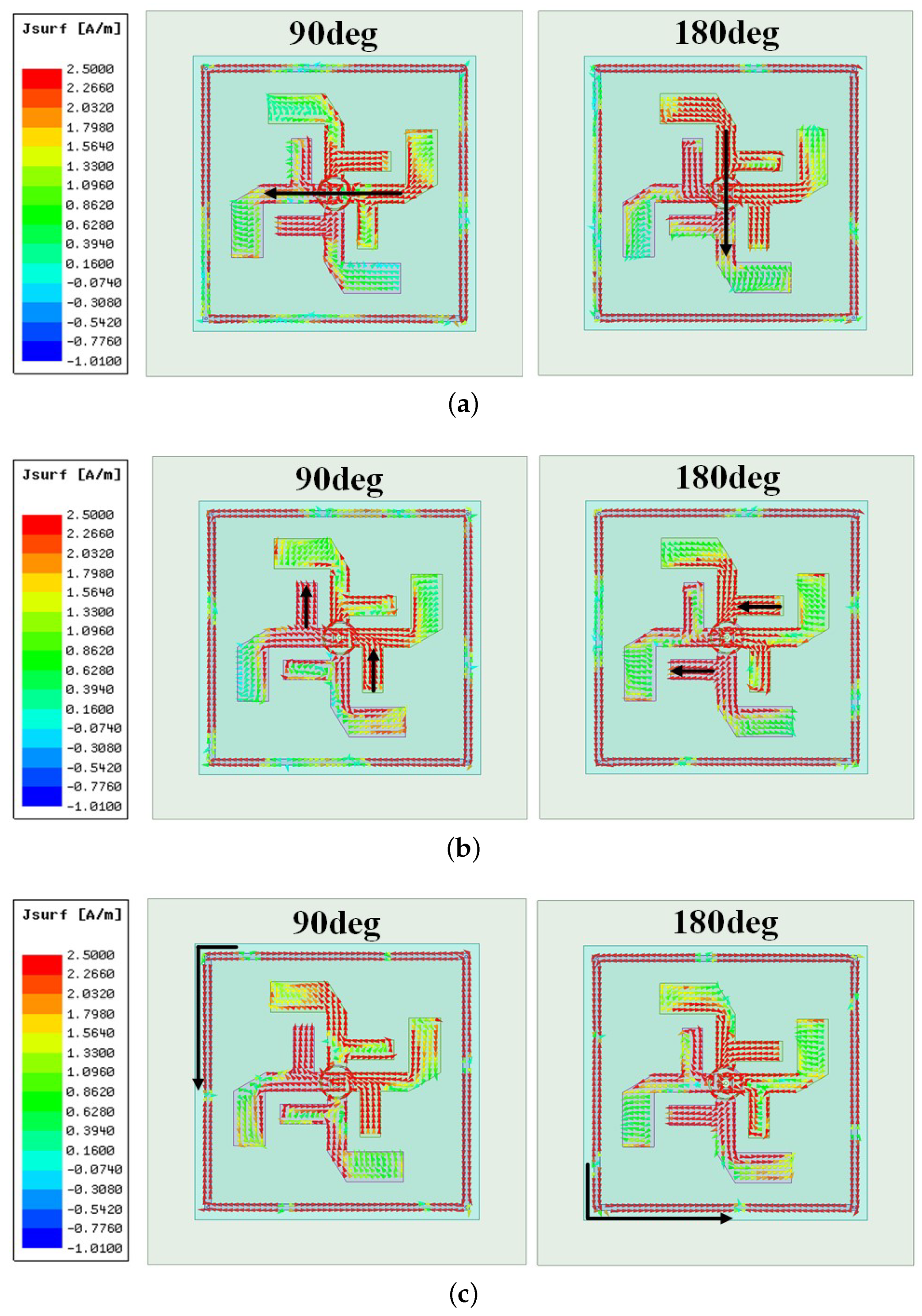
2.3. Surface Current Analysis

The current distribution at T/4 (90 deg) and T/2 (180 deg) on the cross dipole and the rectangular ring metal patch at the three circularly polarized resonating frequencies of 2.01 GHz, 2.33 GHz, and 2.51 GHz are shown in Figure 4. The direction of the current is marked with black arrows. It can be seen that the main current distribution at 2.01 GHz is on the cross-dipole arms and rotating counterclockwise. This indicates that the radiation of this operating frequency is a right-hand circularly polarized wave (RHCP). Similarly, the current at 2.33 GHz is mainly distributed on the loaded open-circuit branches, while the current at 2.51 GHz is mainly distributed on the rectangular ring patch. The current distributions show that the three circularly polarized resonating frequencies are generated by the cross dipole, the loaded open-circuit branches, and the rectangular ring patch, respectively, and all three circularly polarized resonating frequencies show RHCP performance. Thus, a broadband circularly polarized performance can be realized.

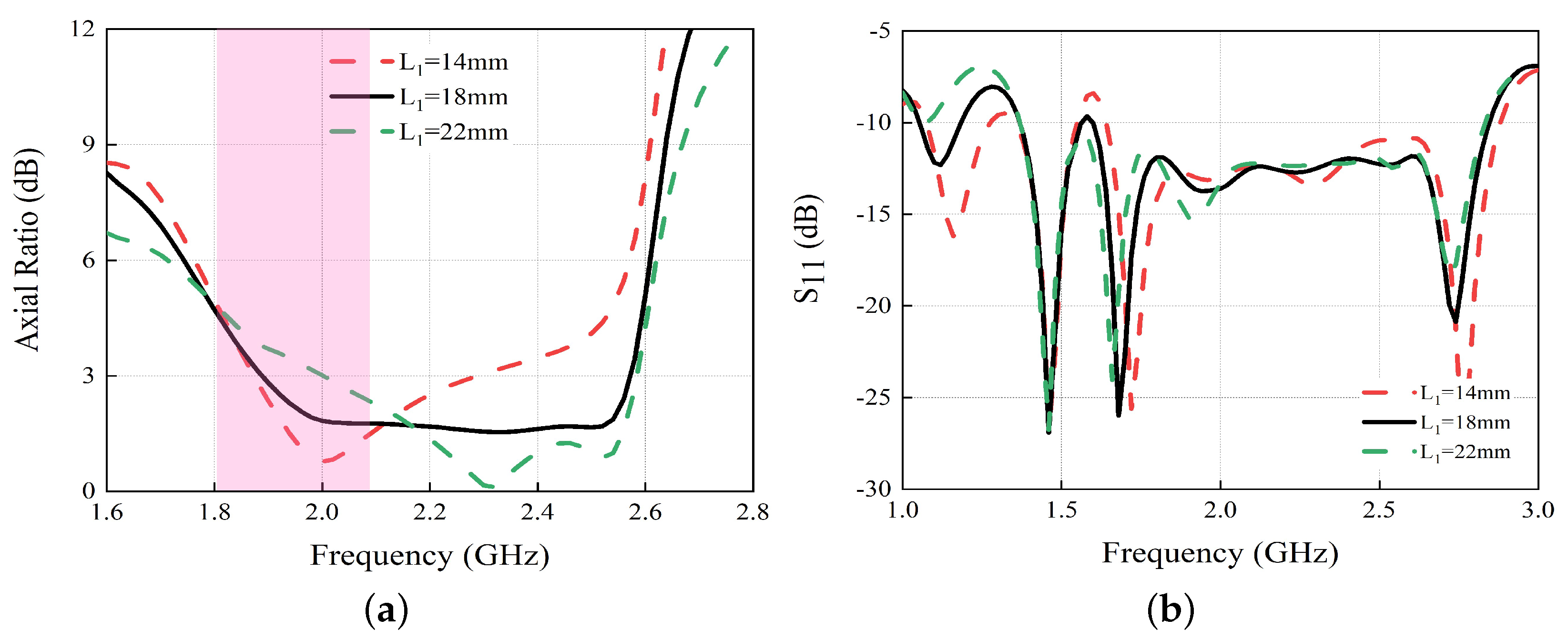
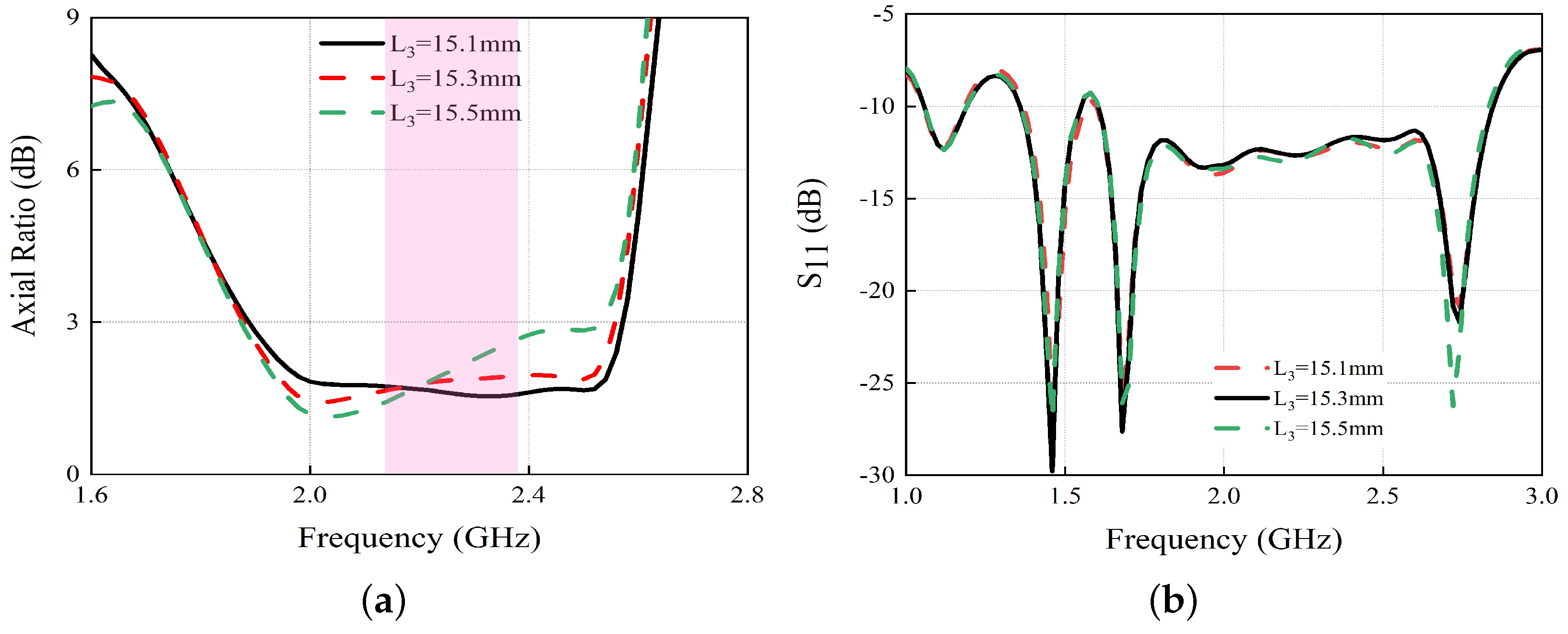
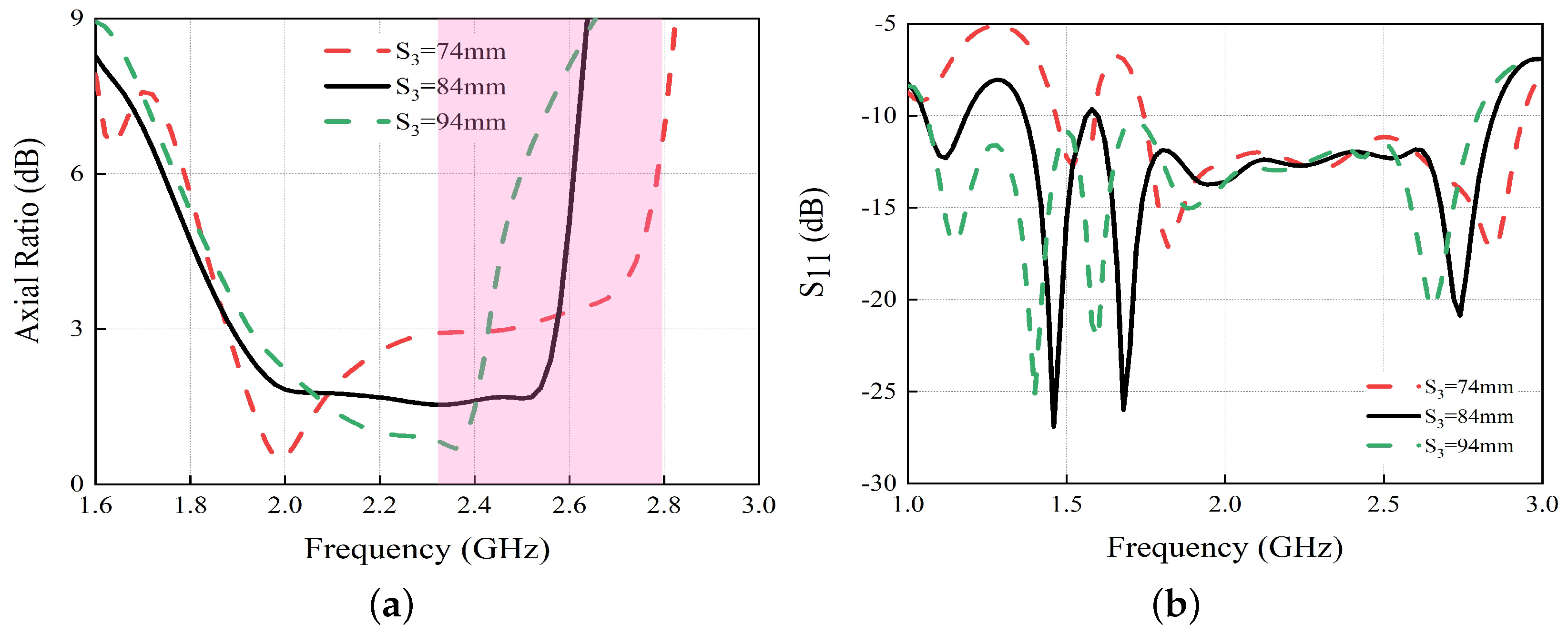
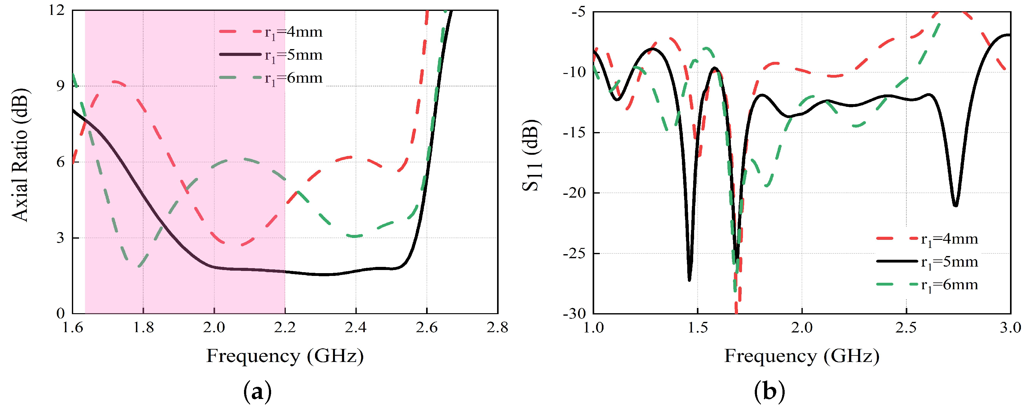
2.4. Antenna Parameter Analysis

To validate the aforementioned analysis, Figure 5, Figure 6, Figure 7 and Figure 8 illustrate the primary parameters’ influences on the axial ratio of the proposed antenna. Initially, the impact of the cross-dipole arm length ( L 1 ) on antenna performance is examined. Our observations indicate that adjusting L 1 leads to a shift in the circularly polarized resonating frequency at 2.01 GHz, while the other two resonant frequencies at 2.33 GHz and 2.51 GHz remain unchanged. This confirms that the operating frequency is generated by the cross-dipole arms. Moreover, the parameter r 1 also affects the circularly polarized resonating frequency at 2.01 GHz. This is because the main structure of the cross-dipole antenna is formed by the three-quarter circular ring ( r 1 ) and dipole arms and the parameter r 1 has some influences on the impedance matching. Next, the effect of the loaded open-circuit stub length ( L 3 ) is examined. It is found that the operating frequency at 2.33 GHz shifts towards higher frequencies when L 3 is shortened and towards lower frequencies when L 3 is elongated. The other two frequencies remain stable, verifying that this particular operating frequency is produced by the loaded open-circuit stubs. Lastly, the influence of the rectangular ring metal patch length ( S 3 ) on antenna performance is assessed. The results show that this parameter significantly affects the operating frequency at 2.51 GHz, confirming that this frequency is generated by the rectangular ring patch and that L 1 and L 3 have little impact on S 11 and gain, while S 3 has a more significant effect on the operating frequencies; the operating frequencies move towards lower frequencies when S 3 increases, and vice versa. The antenna parameters were optimized using H F S S 19.2. Optimal circularly polarized performance was achieved when L 1 = 18 mm, r 1 = 5 mm, S 3 = 84 mm, and L 3 = 15.1 mm.

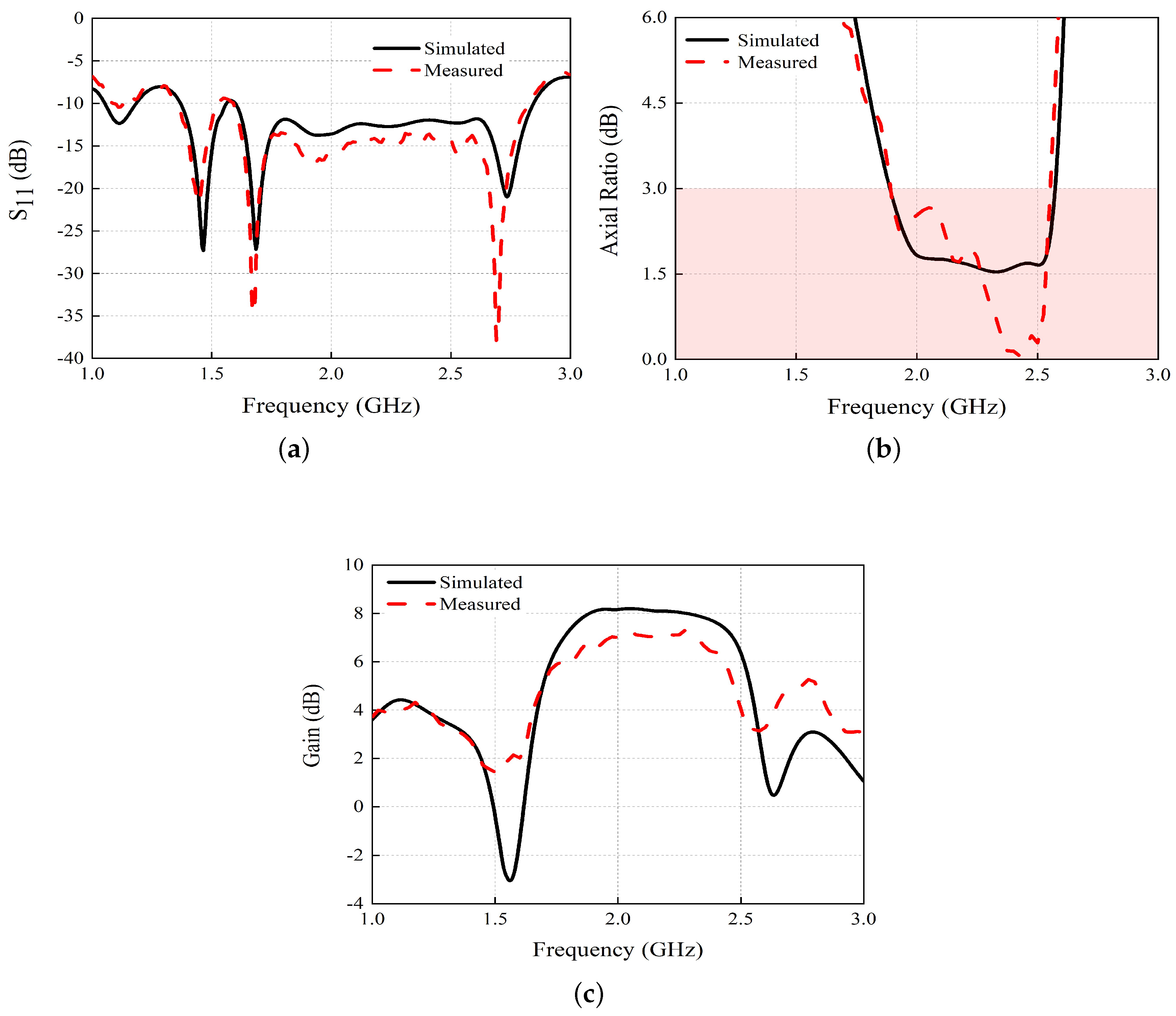
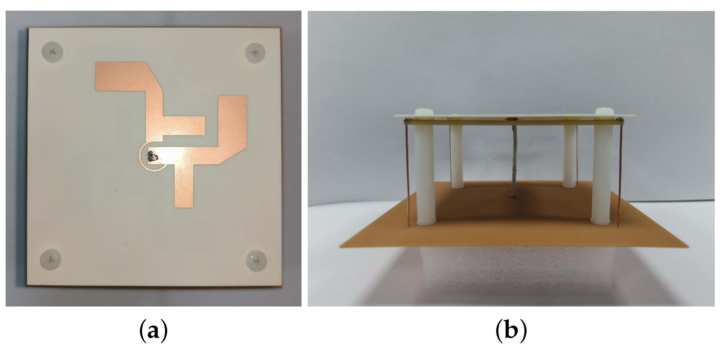
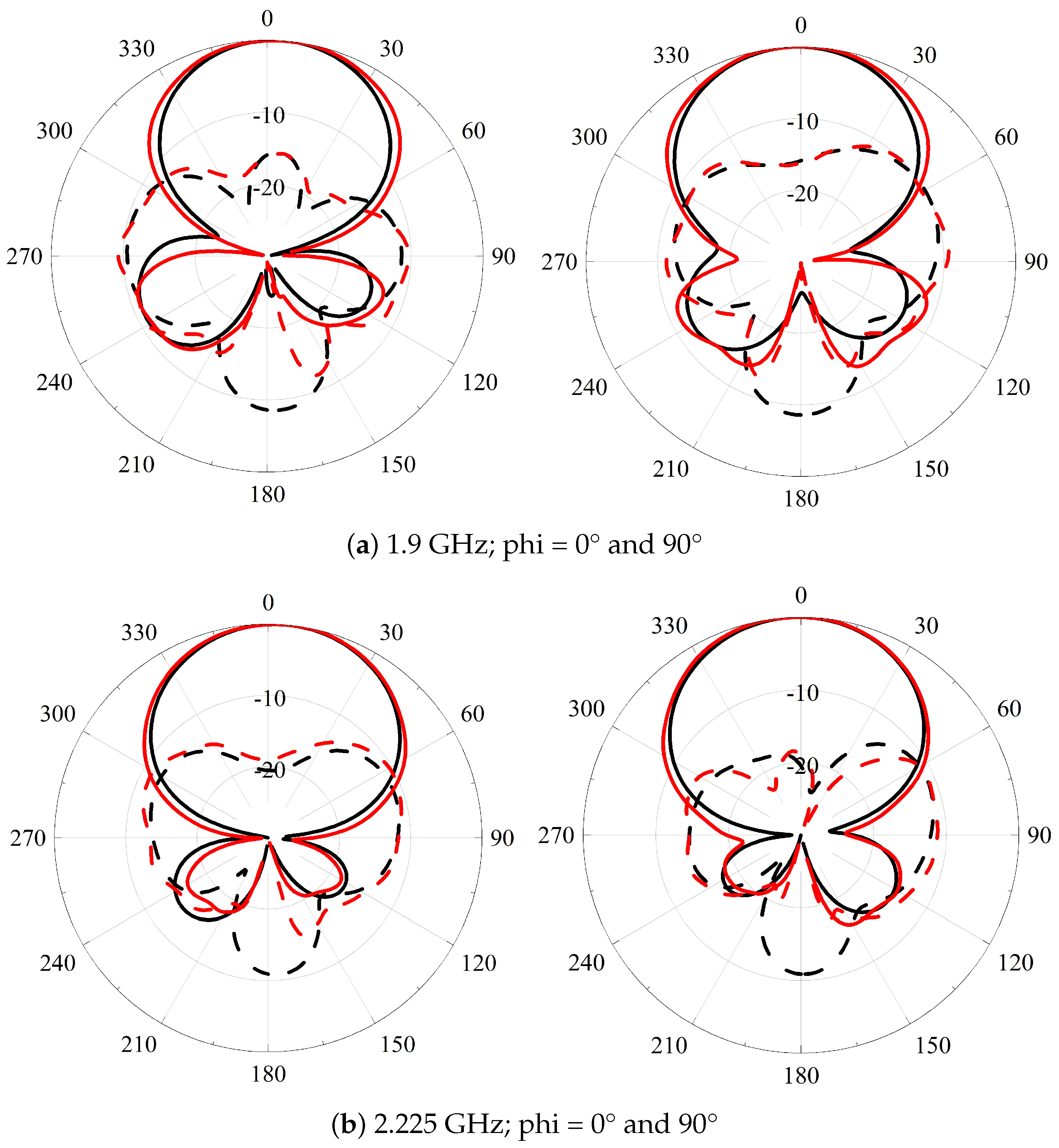
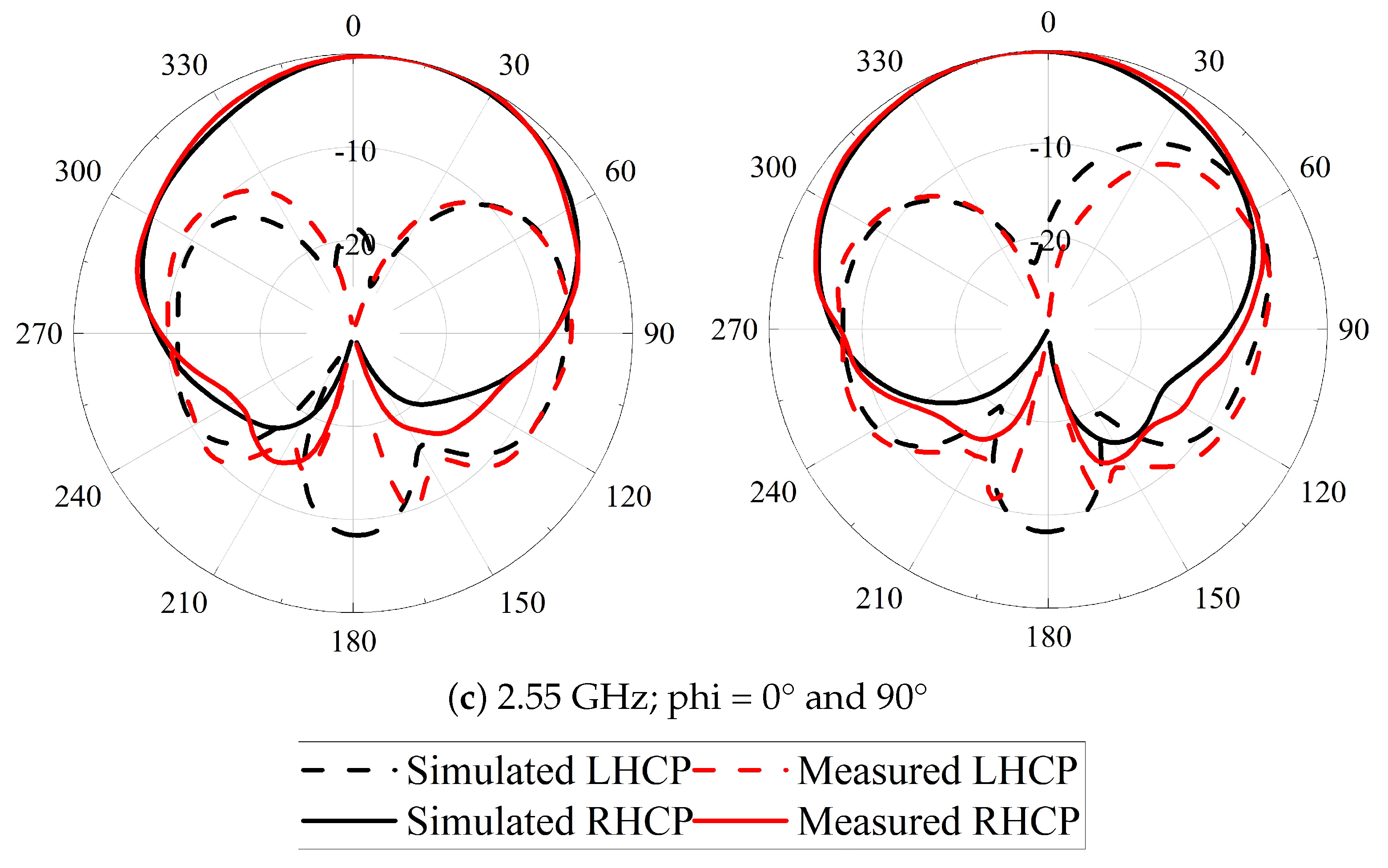
3. Experiment Results

To address the advantages of the proposed work, a performance comparison of the relevant circularly polarized antennas is shown in Table 1. It can be seen that the proposed antenna has both broadband and high gain performance.
The proposed broadband circularly polarized cross-dipole antenna was fabricated and tested. The S-parameters were measured using an Agilent N5227A vector network analyzer, while the axial ratio (AR), gain, and radiation pattern results were obtained with a Satimo system. Figure 9 displays the simulated and measured S-parameters, axial ratio, and realized gain. It is evident that the simulation impedance bandwidth of −10 dB spans 56.1% (1.60 GHz to 2.85 GHz). The antenna’s 3 dB axial ratio bandwidth is 30.5% (1.89 GHz to 2.57 GHz), with a consistent gain of 8.1 dB within the passband. The measured impedance bandwidth of −10 dB is 44.5% (1.78 GHz to 2.80 GHz). The 3 dB axial ratio bandwidth is 29.2% (1.9 GHz to 2.55 GHz), and the gain within the passband is maintained at 7.5 dB. When compared to the simulation results, the impedance bandwidth remains largely unchanged. However, the gain in the passband is reduced by approximately 0.6 dB, which can be attributed to fabrication and testing inaccuracies. The fabricated antenna is shown in Figure 10. And the normalized radiation patterns of the proposed antenna at 1.9 GHz, 2.225 GHz, and 2.55 GHz are illustrated in Figure 11. These patterns show a strong agreement between the simulation and measurement results. The antenna’s primary radiation direction is stable throughout the entire operational bandwidth. In the radiation direction, the strength of the main polarization field (right circular polarization) is approximately 20 dB stronger than the cross-polarization field (left circular polarization). This confirms that the antenna exhibits effective right circular polarization.
Table 1 summarizes the performance comparison of the relevant circularly polarized antennas, highlighting the advantages of the proposed design. Notably, the proposed antenna offers both broadband capabilities and high gain performance.

4. Conclusions

A high-gain broadband circularly polarized cross-dipole antenna has been proposed. The antenna employs two pairs of cross dipoles and a pair of three-quarter rings to generate circular polarization radiation. By loading open-circuit branches onto the four arms of the two pairs of crossed dipoles, a new circular polarization radiation frequency is introduced. A rectangular ring patch placed directly beneath the crossed dipoles creates a third axial ratio frequency, effectively enhancing the axial ratio bandwidth of the antenna. Metal posts positioned at the four right angles of the rectangular ring patch serve to boost the antenna’s gain. The experimental results reveal that the antenna’s 3 dB axial ratio bandwidth spans 29.2% (1.9 GHz to 2.55 GHz), with a consistent gain of 7.5 dB throughout the passband, demonstrating good circular polarization radiation characteristics. Consequently, the proposed antenna holds significant potential for applications in satellite communication, emergency communication, and environment monitoring systems.

Author Contributions

Conceptualization, X.L. and W.L.; methodology, W.L.; software, C.L.; validation, X.L., W.L. and C.L.; formal analysis, W.L.; investigation, W.L.; resources, C.L.; data curation, C.L.; writing—original draft preparation, W.L.; writing—review and editing, X.L.; visualization, C.L.; supervision, X.L.; project administration, X.L.; funding acquisition, C.L. All authors have read and agreed to the published version of the manuscript.

Funding

This work was supported by the College Student Innovation and Entrepreneurship Training Program Project under Grant 202411819058. (Corresponding author: X.L.)

Data Availability Statement

Data are contained within the article.

Conflicts of Interest

The authors declare no conflicts of interest.

References

  1. Chen, H.M.; Wang, Y.K.; Lin, Y.F.; Lin, C.Y.; Pan, S.C. Microstrip-Fed Circularly Polarized Square-Ring Patch Antenna for GPS Applications. IEEE Trans. Antennas Propag. 2009, 4, 1264–1267. [Google Scholar] [CrossRef]
  2. Tan, M.T.; Wang, B.Z. A Dual-Band Circularly Polarized Planar Monopole Antenna for WLAN/Wi-Fi Applications. IEEE Antennas Wirel. Propag. Lett. 2016, 15, 670–673. [Google Scholar] [CrossRef]
  3. Narbudowicz, A.; John, M.; Sipal, V.; Bao, X.; Ammann, M.J. Design Method for Wideband Circularly Polarized Slot Antennas. IEEE Trans. Antennas Propag. 2015, 10, 4271–4279. [Google Scholar] [CrossRef]
  4. Ge, L.; Li, M.; Li, Y.; Wong, H.; Luk, K.M. Linearly Polarized and Circularly Polarized Wideband Dipole Antennas With Reconfigurable Beam Direction. IEEE Trans. Antennas Propag. 2018, 4, 1747–1755. [Google Scholar] [CrossRef]
  5. Hasani, H.; Silva, J.S.; Capdevila, S.; García-Vigueras, M.; Mosig, J.R. Dual-Band Circularly Polarized Transmitarray Antenna for Satellite Communications at (20, 30) GHz. IEEE Trans. Antennas Propag. 2019, 8, 5325–5333. [Google Scholar] [CrossRef]
  6. So, K.K.; Wong, H.; Luk, K.M.; Chan, C.H. Miniaturized Circularly Polarized Patch Antenna With Low Back Radiation for GPS Satellite Communications. IEEE Trans. Antennas Propag. 2015, 12, 5934–5938. [Google Scholar] [CrossRef]
  7. Lin, Q.W.; Wong, H.; Zhang, X.Y.; Lai, H.W. Printed Meandering Probe-Fed Circularly Polarized Patch Antenna with Wide Bandwidth. IEEE Antennas Wirel. Propag. Lett. 2014, 13, 654–657. [Google Scholar] [CrossRef]
  8. Yang, F.; Zhang, X.X.; Ye, X.; Rahmat-Samii, Y. Wide-band E-shaped patch antennas for wireless communications. IEEE Trans. Antennas Propag. 2001, 7, 1094–1100. [Google Scholar] [CrossRef]
  9. Dai, W.J.; Huang, Z.F. A broadband circularly polarized stacked microstrip patch antenna with parasitic elements. Int. J. Microw.-Comput.-Aided Eng. 2021, 11, e22842. [Google Scholar] [CrossRef]
  10. Baik, J.-W.; Lee, K.-J.; Yoon, W.-S.; Lee, T.-H.; Kim, Y.-S. Circularly polarised printed crossed dipole antennas with broadband axial ratio. Electron. Lett. 2008, 6, 785–786. [Google Scholar] [CrossRef]
  11. He, Y.; He, W.; Wong, H. A Wideband Circularly Polarized Cross-Dipole Antenna. IEEE Antennas Wirel. Propag. Lett. 2014, 13, 67–70. [Google Scholar] [CrossRef]
  12. Elsaid, M.; Mahmoud, K.R.; Hussein, M.; Hameed, M.F.; Yahia, A.; Obayya, S.S. Ultra-wideband circularly polarized crossed-dual-arm bowtie dipole antenna backed by an artificial magnetic conductor. Microw. Opt. Technol. Lett. 2019, 12, 2801–2810. [Google Scholar] [CrossRef]
  13. He, W.; He, Y.; Zhang, L.; Wong, S.W. An Improved Broadband Circularly Polarized Cross-Dipole Antenna with an AMC Reflector. In Proceedings of the 2019 IEEE International Conference on Microwaves, Antennas, Communications and Electronic Systems (COMCAS), Tel-Aviv, Israel, 4–6 November 2019; pp. 1–3. [Google Scholar] [CrossRef]
  14. Chen, Q.; Zhang, H.; Yang, L.C.; Zhong, T. A metasurface-based slit-loaded wideband circularly polarized crossed dipole antenna. Int. J. Microw.-Comput.-Aided Eng. 2018, 1, e21173. [Google Scholar] [CrossRef]
  15. Saurav, K.; Sarkar, D.; Srivastava, K.V. Wide-band circularly polarized cavity backed crossed dipole antenna. In Proceedings of the 2017 XXXIInd General Assembly and Scientific Symposium of the International Union of Radio Science (URSI GASS), Montreal, QC, Canada, 19–26 August 2017; pp. 1–4. [Google Scholar] [CrossRef]
  16. Li, R.; Li, B.; Du, G.; Sun, H.; Sun, X. A wideband circularly polarized antenna array with sequential rotation feed. Int. J. Microw.-Comput.-Aided Eng. 2020, 9, e22322. [Google Scholar] [CrossRef]
  17. Wang, L.; Chen, K.W.; Huang, Q.; Shao, W.H.; Fang, W.X.; Lu, G.G.; Huang, Y.; En, Y.F. Wideband circularly polarized cross-dipole antenna with folded ground plane. IET Microw. Antennas Propag. 2021, 5, 451–456. [Google Scholar] [CrossRef]
  18. Agrawal, M.; Kumar, T. A Wideband Circularly Polarized Antenna Using Substrate Integrated Waveguide and Truncated-Corner Patch Loaded Slot. Wirel. Pers. Commun. 2023, 131, 399–413. [Google Scholar] [CrossRef]
  19. Luo, Y.; Chen, Z.; Hu, Z.; Li, C. Wideband circularly polarised antenna with dual-fed strategy simplification based on common mode and differential mode. IET Microw. Antennas Propag. 2023, 11, 840–845. [Google Scholar] [CrossRef]
  20. Wu, Q.S.; Tang, X.Y.; Du, Z.X.; Zhang, X. An all-metal wideband circularly polarized single-patch antenna based on TM11 mode. Electron. Lett. 2024, 3, e13102. [Google Scholar] [CrossRef]
  21. Ding, K.; Gao, C.; Qu, D.; Yin, Q. Compact Broadband Circularly Polarized Antenna with Parasitic Patches. IEEE Trans. Antennas Propag. 2017, 9, 4854–4857. [Google Scholar] [CrossRef]
Figure 1. A high-gain broadband circularly polarized cross-dipole antenna. (a) Top view. (b) Side view. ( S 1 = 120 , S 2 = 90.4 , S 3 = 84 , W 1 = 10 , W 2 = 6 , W 3 = 6.5 , W 4 = 2 , L 1 = 18 ,   L 2 = 17.8 , L 3 = 15.1 , L 4 = 7.2 , h 1 = 0.8 , h 2 = 1 , h 3 = 2 , h 4 = 41 , r 0 = 0.46 , r 1 = 5 , r 2 = 5.5 , q = 2.3 , all   in   mm ).
Symmetry 16 01016 g001
Figure 2. Reference antenna structure diagrams. (a) Ant.I. (b) Ant.II. (c) Ant.III.
Symmetry 16 01016 g002
Figure 3. Results of reference antenna. (a) S 11 . (b) AR. (c) Gain.
Symmetry 16 01016 g003
Figure 4. Current distribution of the antenna from 90 degrees to 180 degrees at 2.01 GHz, 2.33 GHz, and 2.51 GHz, respectively. (a) 2.01 GHz. (b) 2.33 GHz. (c) 2.51 GHz.
Symmetry 16 01016 g004
Figure 5. Simulation results for Ant.III with varying lengths of the dipole arm L 1 . (a) AR. (b) S 11 .
Symmetry 16 01016 g005
Figure 6. Simulation results for Ant.III with varying lengths of the loaded open-circuit stub L 3 . (a) AR. (b) S 11 .
Symmetry 16 01016 g006
Figure 7. Simulation results for Ant.III with varying lengths of the rectangular ring metal patch S 3 . (a) AR. (b) S 11 .
Symmetry 16 01016 g007
Figure 8. Simulation results for Ant.III with varying radius of the three-quarter circular ring r 1 . (a) AR. (b) S 11 .
Symmetry 16 01016 g008
Figure 9. Simulated and measured results of the antenna. (a) S 11 . (b) AR. (c) Gain.
Symmetry 16 01016 g009
Figure 10. Photographs of the fabricated antenna. (a) Top view. (b) Side view.
Symmetry 16 01016 g010
Figure 11. Radiation patterns of the proposed antenna at (a) 1.9 GHz, (b) 2.225 GHz and (c) 2.55 GHz (black lines: simulation, red lines: measurement).
Symmetry 16 01016 g011aSymmetry 16 01016 g011b
Table 1. Comparison of the proposed and reported CP cross-dipole antennas.
Ref.Size
( λ 0 × λ 0 × λ 0 )
Type S 11
BW (%)
AR
BW (%)
Overl.
BW (%)
Ave.
Gain (dB)
[11]0.36 × 0.36 × 0.2cross-dipole50.2 (1.99–3.22 GHz)2753.76.8
[12]0.77 × 0.77 × 0.14cross-dipole50.5 (0.8–1.34 GHz)26.452.28
[13]0.65 × 0.65 × 0.1cross-dipole47.3 (1.81–2.93 GHz)25.353.47
[14]0.37 × 0.37 × 0.14cross-dipole31.6 (2–2.75 GHz)23.273.47.1
[15]0.68 × 0.68 × 0.21cross-dipole64.6 (2.05–3.67 GHz)22.8935.47.6
[16]0.42 × 0.42 × 0.12dipole
feed network
93 (1.56–4.27 GHz)80.789.75
[17]0.49 × 0.49 × 0.12patch
circle ring
100 (0.95–2.85 GHz)85.785.74
[18]1 × 1 × 0.06patch
SIW
20 (10.87–3.275 GHz)6.40.326
[19]0.53 × 0.35 × 0.005dual-feed
dipole
40 (1.6–2.40 GHz)27.167.80
[20]0.96 × 0.96 × 0.03all mental
patch
12.2 (1.44–1.62 GHz)6.956.63
Pro.0.64 × 0.64 × 0.03cross-dipole55.2 (1.60–2.85 GHz)29.252.97.5
Disclaimer/Publisher’s Note: The statements, opinions and data contained in all publications are solely those of the individual author(s) and contributor(s) and not of MDPI and/or the editor(s). MDPI and/or the editor(s) disclaim responsibility for any injury to people or property resulting from any ideas, methods, instructions or products referred to in the content.

