Article

Formation of Symmetric Gradient Microstructure in Carbon Steel Bars

by
Irina Volokitina
1,*,
Andrey Volokitin
2,* and
Bolat Makhmutov
3
1
Department of Metallurgy and Material Science, Karaganda Industrial University, Temirtau 101400, Kazakhstan
2
Department of Metal Forming, Karaganda Industrial University, Temirtau 101400, Kazakhstan
3
Vice-Rector for Research and International Cooperation, Karaganda Industrial University, Temirtau 101400, Kazakhstan
*
Authors to whom correspondence should be addressed.
Symmetry 2024, 16(8), 997; https://doi.org/10.3390/sym16080997
Submission received: 25 June 2024 / Revised: 25 July 2024 / Accepted: 26 July 2024 / Published: 6 August 2024

Abstract

:
In recent years, severe plastic deformation has attracted the most attention as a way to improve the mechanical properties of steel bars. Obtaining ultrafine grains and nanostructures in such bars leads to a strong increase in strength properties but strongly reduces their plastic properties. This study shows that the formation of a gradient microstructure allows simultaneous improvement in the strength and plastic properties of carbon steel bars, taking into account the symmetry of the microstructure distribution from the center of machining. A new combined technology is proposed to obtain such a microstructure. This technology consists of drawing bars from medium carbon steel on a radial-displacement rolling mill and carrying out subsequent drawing. Steel bars with a diameter of 30 mm were strained in three passes to a diameter of 16 mm at room temperature. The results show that the average value of microhardness in the center, neutral, and surface areas for the three straining cycles were 1890 MPa, 2335 MPa, and 2920 MPa, respectively. This symmetrical distribution of microhardness confirms the gradient microstructure. Strength characteristics also increased almost twofold: the yield strength increased from 330 to 735 MPa, and the ultimate strength increased from 600 MPa to 1025 MPa. Relative elongation decreased from 18 to 14 MPa, and relative reduction decreased from 40 to 31%, but remained at a fairly good level for AISI 1045 steel. The validity of all results was confirmed through numerous experiments using a set of traditional and modern research methods, which included optical, scanning, and transmission microscopy. EBSD analysis allowed precise positioning of the field of vision for studying microstructural changes across the entire bar cross-section. All of these methods used together, including tensile testing of the mechanical properties and the fractographic method, allow us to assess changes in microhardness and the reproduction of results.

1. Introduction

The main purpose of using rebar in construction is to strengthen concrete. Concrete in its pure form has little resistance to tensile and bending loads. Reinforcement bars distribute the load more evenly throughout the structure, allowing it to withstand the effects of heavy loads and external factors such as wind and earthquakes. Any construction process of reinforcing concrete structures is associated with the use of various types of rebars. The standard length of a rebar in its original state is 6 or 12 m. Accordingly, scraps of various lengths remain when creating the reinforcing part of the concrete base. These are then subject to utilization and subsequent remelting. This entails the use of additional energy resources related to heating for melting, the production of rolled products, etc. [1,2].
We propose the recycling of rebar scraps to save energy resources. For this purpose, rebar scraps were sorted depending on their original diameter and subjected to additional processing using the new radial-displacement drawing technology. This produced a finished product in the form of thinner bars from recycled scraps [3,4].
In recent years, there has been a steady trend in the production of reinforcement bars for reinforced concrete structures to increase the strength of rolled products while reducing the consumption of expensive alloying elements [5,6]. When reinforcement bars are used in reinforced concrete structures, they shall meet such requirements as sufficient ductility under long-term and short-term loads and operation at high and low temperatures, as well as the required high-strength characteristics.
It is possible to improve the mechanical and processing properties of carbon steel by grinding the microstructure to ultra- and nano-scale dimensions. Severe plastic deformation (SPD) techniques are the most recently used methods for microstructure refinement [7,8,9,10,11,12,13]. As a result of the SPD of metallic materials, the length of grain boundaries increases several times and the dynamic and static dilatation of the atoms of the crystal lattice is significantly changed. As a result of microstructure fragmentation, dislocations create additional boundaries, resulting in the grain and sub-grain boundary lengths increasing by several orders of magnitude. On the other hand, high stresses and distortions of the crystal lattice lead to lattice dilatations, which are reflected in changes in the interatomic distances and significant static and dynamic atomic displacements. Therefore, even non-ferrous metals and alloys processed in this way can be harder than high-strength steel [14,15,16]. However, achieving this strength often leads to increased brittleness and results in in-service failure. Hence, the main challenge lies in achieving a compromise between the strength and plastic properties of the metal.
Also, the implementation of SPD methods is possible in discrete processes. However, it is difficult to achieve in the production of long products with unavoidable tensile stresses where rolling or drawing is used [17,18]. Such methods are not suitable for rebar processing. One of the solutions to this problem is to obtain a gradient microstructure in the material [19,20,21,22,23,24]. The grain size in such metals increases from a nano-scale state at the surface to a coarse-grained state in the center. This distribution of microstructure is an efficient way to increase the overall ductility of the bar and its surface strength [25,26,27]. This method will increase the prospects for the use of such bars with a gradient microstructure in mechanical engineering and construction. There is an increased plasticity reserve in such a microstructure distribution in comparison with the traditional drawing process. Then, such bars can be further processed with large degrees of deformation without carrying out intermediate annealing. Therefore, it is of interest to study the formation of such gradient microstructures in carbon steel bars, since the combination of a hard surface layer and a relatively “soft” core relieves the stress concentration and improves the overall ductility of the product, its wear resistance, and its load distribution.
One of the promising processes allowing us to obtain gradient microstructures in bars is cross rolling (CR) and radial-displacement rolling (RDR), the latter of which is one of the varieties patented in the literature [28]. Its difference from cross rolling is that it involves the rolling of a solid bar using a three-roll pattern with large values of feed angles. Compared to known processes such as equal-channel angular pressing or Bridgman anvil deformation, RDR has a number of advantages: in particular, it requires lower values of deformation force, it entails no restrictions on the length of the final workpiece, and it is suitable for rolling with significant drawing ratios without fracture [29].
According to [28], it is convenient to divide the cross-section of a bar after deformation with the RDR method into three parts: central, neutral, and surface parts. The thickness of the surface zone is equal to 0.3–0.7 of the workpiece radius (measured from the workpiece surface). The value of the neutral zone is 0.05–0.1 of the radius, and that of the central zone is 0.25–0.6 of the radius (measured from the workpiece center) [28]. Based on this, it can be concluded that a stress-state scheme close to all-round compression with large shear deformations is implemented in the deformation zone in RDR. In the outer layer, each small trajectory-oriented element is subjected to compression deformation along the radius (diameter) of the workpiece; deformation occurs along the direction of displacement and tensile deformation occurs across the helical trajectory. Elements of the metal structure take an isotropic isolated form, separated from each other by particles of high dispersity. The structural banding and reticulation trend are suppressed due to the overall drawing of the workpiece. Such conditions of metal deformation do not exist in any of the known fixed processes of bar production. In the whole volume of the workpiece, a helicoidal flow of metal in the gauge along the specified trajectories with the braking of surface layers and acceleration of central ones creates the effect of a volumetric macroshift. Macroshift deformations are maximally favorable for achieving the defect-free plastic deformation of metal, and at the same time contribute to a significant increase in the technological deformability of workpieces [28].
However, bars of only limited length can be deformed by this method. The authors of [30] noted that very expensive planetary stands are used for deforming long bars using the RDR method.
Although gradient materials have shown promising results, most research is still focused on non-ferrous metals and alloys [31,32,33]. In [31], it was found that high-temperature RDR affects the distribution of strains and stresses along the cross-section of aluminum bars. The bars were subjected to RDR at 480 °C in four passes. The simulations revealed a gradient distribution of strain across the cross-section of the deformed aluminum bars. The strain was lowest in the center part of the samples, while the peripheral zones had the highest strain with a ratio greater than 1.5 in both alloys. In accordance with the gradient structure concept, alloy 7075 has the ability to combine high ductility and strength that is equivalent to those achieved with other industrial techniques under much more severe deformation conditions. Thus, RDR can be considered as an effective industrial technology for the production of high-strength aluminum alloys providing a combination of high strength and ductility of the processed material.
Experimental studies of the technological capabilities of RDR for obtaining titanium alloy bars with gradient microstructure from small diameter bars have been carried out in the literature [32]. The influence of rolling routes and thermal deformation conditions on the macro- and microstructure of the obtained bars, as well as on their mechanical properties, was studied. The production scheme, which has been experimentally confirmed at RDR mills, can be proposed as a basis for the high-tech production of mini rolled products with flexible production programs.
There are studies that consider the possibility of combining RDR and drawing [34]. Traditional drawing as a final operation after various SPD processes can eliminate all the disadvantages (geometric irregularities, pores, etc.) caused by pre-deformation [35,36,37].
Reference [35] describes how the microstructure and mechanical properties of copper wire change during wire deformation in a rotating equal-channel step matrix and subsequent drawing. As a result of deformation, an ultrafine-grained gradient microstructure with a high component of high-angle grain boundaries was obtained. The use of such hardened copper wire in construction will reduce the weight of the structure by decreasing the diameter of the wire.
“Pressing-drawing” is a new method of wire deformation that was developed in the literature [36]. This method is more effective than the previously known methods of obtaining metal with ultrafine-grained structure. Thus, technically pure copper deformed by the pressing–drawing process was taken as an example. It is shown that the combination of ECAP technology and traditional drawing leads to the formation of a structure with fine, homogeneous, equiaxed grains with predominantly large-angle boundaries. These results were achieved by applying shear deformations occurring in an equal-channel matrix, which led to the formation of a material structure different from that formed by standard methods.
Based on the above literature review, it can be concluded that it is necessary to pay special attention to both traditional and modern rolling and drawing methods in the context of modern production tasks related to the production of high-quality bars. Traditional methods based on years of experience have certain advantages such as stability and predictability of results. However, they can be limited in terms of achieving the highest quality standards and are often characterized by higher production costs. On the other hand, new technologies such as SPD offer new opportunities to improve bar quality, reduce costs and increase productivity. The key approach to solving the problem of bar production is the creation of modular technological processes combining the advantages of traditional and modern methods [38,39,40]. This approach improves the production process, taking into account specific product quality requirements, reduces the disadvantages of each individual method and reduces the overall production time.
The use of heat treatment in the production of carbon steel bars results in an increase in both the length of the technological cycle and increases the cost of bar production. The development of new technical processes for producing bars requires methods that enhance application efficiency, specifically metal pressure treatment of metals. We propose a completely new combined technology for deforming carbon steel bars on this basis. It consists of the combination of radial-shift broaching (where the deformation is carried out in rolls disconnected from the drive) and traditional drawing. The rolls are disconnected from the drive in order to allow the bar to be drawn. In this case, conventional RDR cannot be combined with drawing due to the high axial rotation frequency of the bar during deformation.
The material used for reinforcing concrete can have a smooth or ribbed surface. A ribbed surface can be eliminated in the process of deformation by our proposed technology by drawing process.
The practical significance and scientific novelty of this work is the development of a completely new technology of combined deformation and study of its influence on the evolution of microstructure and change in mechanical characteristics of carbon steel bars.
The economic effect will be achieved due to the possibility of obtaining high-strength long bars from carbon steel with symmetrical gradient structure when implementing the results obtained in the course of this work. It is possible to predict the physical and mechanical properties of the finished product by obtaining symmetrically distributed microstructure in the workpiece from the center to the periphery, which will allow increasing its operational properties.

2. Materials and Methods

Modern materials science is constantly developing technologies to obtain materials with improved properties. Special attention is paid to the development of new methods of metal processing aimed at improving strength, wear resistance and other key characteristics.
The combined technology of radial-shift broaching and drawing (RSB-drawing) was studied through laboratory experiments on bars made of carbon steel AISI 1045 (with added manganese). Their chemical composition is shown in Table 1. Workpieces were annealed at 740 °C before deformation to eliminate the influence of other manufacturing processes and to obtain a more homogeneous microstructure. After that, the following mechanical properties were obtained: microhardness is 1515 MPa, ultimate strength is 600 MPa, yield strength is 330 MPa, relative reduction is 40%, and relative elongation is 18%.
There was a task at the university to obtain long bars with given characteristics. Standard methods such as radial displacement rolling in planetary stands were not suitable due to lack of appropriate equipment. An alternative solution such as a combination of radial-shift broaching (deformation will be carried out in rolls disconnected from the drive) on the PCP-10/30 mill (MISIS, Moscow, Russia) and conventional drawing on the B-1/550 M mill (Chelyabinsk, Russia) was proposed (Figure 1). The process involves pulling a bar through cone rolls that are arranged at an angle of 120° to each other. This configuration ensures simultaneous tensile, compressive and torsional movement of the workpiece resulting in uniform strain distribution and increased homogeneity of the material structure. The combination of broaching and drawing reduces the machining time as the bar is deformed and profiled simultaneously. The pull of the bar through the rolls and die simultaneously causes tensile stresses that decrease the drawing force. The force is reduced because of the formation of helical dips on the bar (Figure 2) following the radial-shift broaching stage. These dips do not come into contact with the die during the drawing stage. This results in a 15–17% reduction in force. The bar is deformed through both deforming tools because of the gripper action. The bar is twisted in the gap between these tools. The PCP-10/30 mill has been upgraded by installing a pulling device, which is shown under number 1 in Figure 1.
The deformation was performed at room temperature in 3 passes as shown in Table 2.
The diameter of the bar up to the radial shear broaching (D1) was 30 mm. The bar was fed into the roll bite of the PCP-10/30 mill. Next, radial-shift broaching was performed up to a diameter (D2) of 25 mm. The velocity of the workpiece at the roll inlet (V1) during the first pass was 0.01 m/s and at the outlet (V2) was 0.014 m/s. The degree of deformation (ε) for the first pass was 30.56%; the logarithmic degree of deformation (εln) was 0.36. Next, a 25 mm diameter workpiece was fed into a die, where it was reduced to 23 mm (D3). The velocity of the workpiece at the die inlet (V2) was 0.014 m/s, and the velocity at the outlet (V3) was 0.017 m/s. The degree of deformation in this case reached 15.36%. The logarithmic degree of deformation was 0.17. Then, 2 more deformation passes were performed in the same way. The total logarithmic degree of deformation for all three passes was 1.52. This implies that SPD is the name of this technology.
Metallographic analysis was performed on all investigated samples in longitudinal and cross sections after the experiments. Optical, scanning and transmission microscopy were used for analysis. A Lobotom-3 cutting machine (Struers, Switzerland) was used to the bars in half and separate them into small blanks for the study. After that, the samples were studied on a Leica optical microscope (OM) (Wetzlar, Germany). Next, they were poured with liquid epoxy resin, ground, polished on a Tegra Pol grinding and polishing machine (Struers, Switzerland) and pickled. A solution consisting of 2% nitric acid and 98% ethanol was used for pickling. After metallographic analysis on an optical microscope, the same samples were subjected to mechanical tests to determine their hardness according to the Vickers method.
Preparation of samples for the study by transmission microscopy (TEM) on a microscope JEM2100 (Jeol Ltd., Tokyo, Japan) was carried out on a high-precision cutting machine AccuTom-5 (Struers, Switzerland). For this purpose, 0.3 mm thick plates were cut in the cross-section of the bar. Then, 3 mm diameter disks were punched out with a special Gatan puncher. Picking of disks was conducted in automatic mode on electropolishing unit TenuPol (Struers, Switzerland) in A2 electrolyte until a hole appeared in the sample. After that, the process was automatically stopped. The prepared samples were studied under an accelerating voltage of 100 kV.
Additionally, EBSD analysis (electron-probe back grating diffraction microanalysis) was performed. This allows precise positioning of the field of vision to study microstructure changes across the bar cross-section on a Philips XL-30 REM (MEMS and Nanotechnology Exchange, Arlington, VA, USA) field cathode device. Low-angle grain boundaries (LAGBs) and high-angle grain boundaries (HAGBs) were distinguished using statistical analysis. Grain boundaries with angles less than 15° were classified as LAGBs, and those from 15 to 62° were classified as HAGBs.
Vickers microhardness was measured on an Anton Paar hardness tester (LLC Aurora, Russia) according to GOST 9450-76 [41] by pushing in a diamond pyramid with an angle of 136° between opposite faces, with 1 N load and 2 s loading time. The microhardness value was determined by averaging five measurements.
Mechanical uniaxial tensile tests were performed in accordance with GOST 1497-2023 [42] at room temperature on an Instron 5882 (Instron, Norwood, MA, USA) with a strain rate of 1.0 mm/min. The sample strain was measured using an Instron strain gauge (Instron, Norwood, MA, USA). Ten-fold samples of d = 10 mm were used. After tensile testing, the surfaces of the fractured samples were analyzed by scanning electron microscopy on a JEM5910 microscope (Jeol Ltd., Tokyo, Japan).
A total of 75 samples were used for all studies (metallographic analysis, EBSD analysis, uniaxial tensile tests and microhardness measurements), with at least 20 samples for each type of study. Some samples were used for more than one study.

3. Results and Discussion

After the stage of radial-shift broaching only, spiral-shaped dips were observed on the surface of the carbon steel bar (Figure 2). The spiral shape indicates that the material flows through the surface layer of the steel bar during forming in the rolling direction. During deformation, there was rotational movement of particles on the bar surface as well as longitudinal movement of particles throughout the entire bar volume. The drawing stage eliminated this defect (Figure 3).

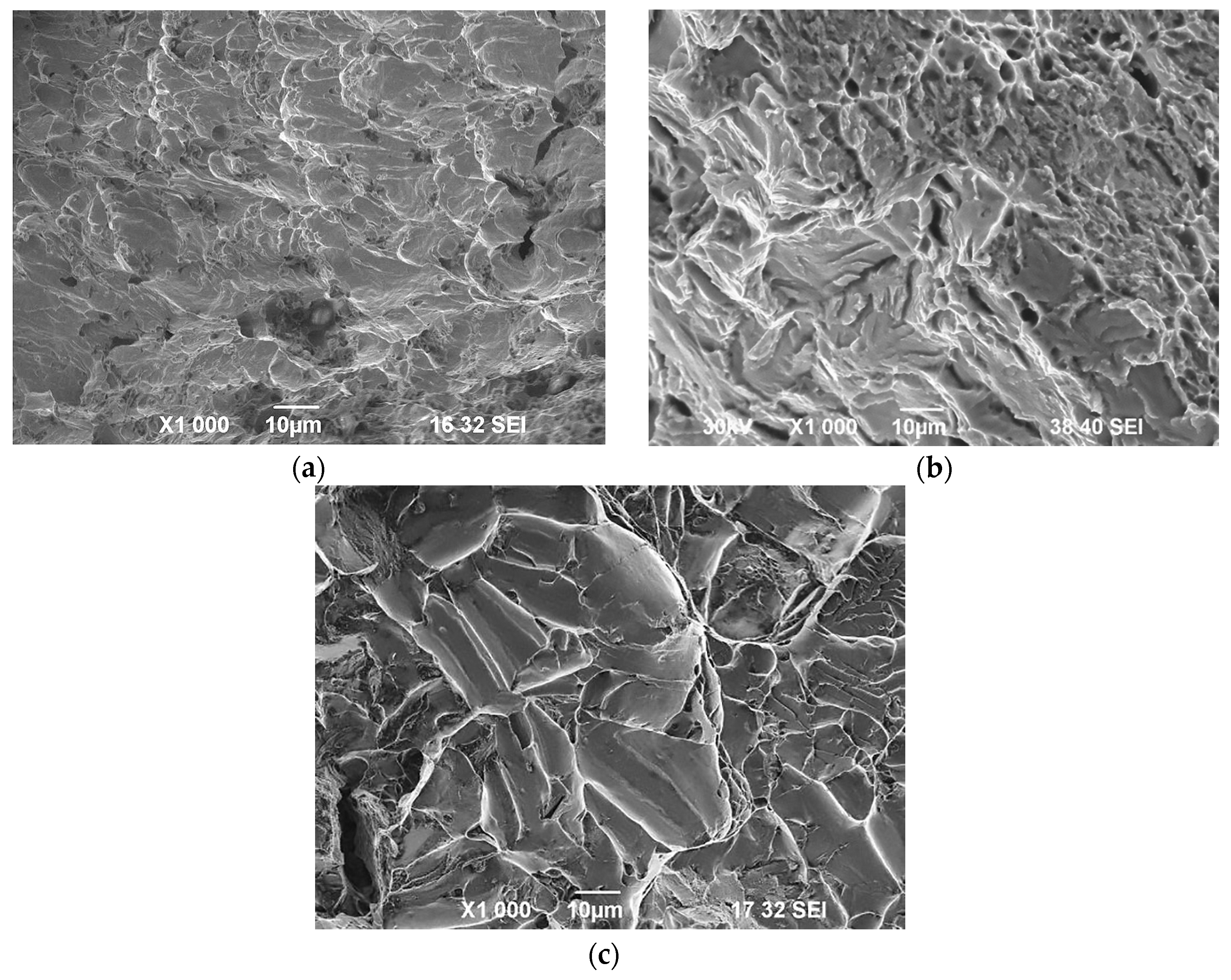
3.1. Metallographic Analysis

The microstructure of the undeformed bar consisted of ferrite–perlite grains. The volume fraction of pearlite is 58% and the distance between pearlite plates is 0.7 µm. The average grain size for ferrite grains is 26 µm.
The study of the metal’s microstructure after deformation by the new method is key to understanding its behavior and properties. A gradient ferro-perlitic structure is observed in the cross section of the bar after deformation by the RSB-drawing method (Figure 4a). According to [28], the bar was divided into three zones, the surface, neutral and central zones, for a more detailed analysis of the gradient microstructure.
Figure 4a shows that the surface zone, where deformation was the most intense, has a significant grain refinement. The average size of ferrite within this zone is approximately 0.5 µm. In the neutral zone, where deformation proceeds less intensively, the structure was also refined, and the sizes of ferrite grains were refined to 2 μm. In the central zone, where the deformation is least significant, the material structure remains almost original, with large ferrite and pearlite grains with an average size of about 7 µm.
TEM was used for a more detailed analysis, and the results are shown in Figure 4b–d. The studies indicate that within the surface zone (Figure 4b), ferrite grains acquire almost equiaxed shape and have thin rectilinear boundaries free of dislocations. The pearlitic plates that make up the steel structure are also crushed, and the distance between them is reduced to 0.2 mm.
In the neutral zone, a bimodal structure consisting of nano- or submicron-scale grains and some fraction of micron-scale grains is observed (Figure 4c). Such a bimodal grain microstructure is formed as a result of partial recrystallization of a highly deformed structure. The volume fraction of fragmented ferrite is not large. Both small grains with a large number of dislocations and large grains with developed substructure were found. The formation of such different grains in the material structure in this case is not related to recrystallization processes, since deformation occurs at room temperature. The heating in the die occurs in the range of 150–165 °C. This indicates that the recrystallization process proceeds by a diffusionless mechanism, so grain enlargement is not due to diffusion but due to textural fusion.
The central zone of the bar (Figure 4d) consists of large grains of deformation origin, with both few and many sub-boundaries.
Next, we analyzed the deformed bar using the EBSD method to quantify the large-angle boundaries in different zones of the bar (Figure 5). Large-angle boundaries are boundaries between crystallites with a difference in lattice orientation of more than 15°. They are an “obstacle” to the movement of dislocations which increases the strength of the material. The formation of new grains occurs as a result of an increase in the disorientation of individual sub-borders as dislocations accumulate within them during deformation, resulting in the transformation of sub-borders into conventional high-angle grain boundaries.
The highest number of HAGBs was observed in the surface zone subjected to the highest stresses. During three deformation cycles, about 50% of grains formed during deformation had an orientation angle of 30° or more. This is because cyclic deformations stimulate the formation of new grains that differ from each other in orientation. Elongated areas separated by both LAGBs and HAGBs are observed in the neutral zone. The central zone underwent the least amount of shear deformation, resulting in the highest concentration of LAGBs.
The disorientation angle diagram (Figure 6) additionally illustrates the distribution of boundaries by disorientation angles in various zones of the bar.
Figure 6 indicates that the proportion of HAGBs decreases as one moves away from the surface zone to the central zone. The distribution of HAGBs share in the superficial zone reaches 65%, in the neutral zone reaches 49%, and in the central zone reaches 28%.
The formation of a gradient microstructure with a high HAGB content in the surface zone is the result of a complex interaction between two technologies: radial-shift broaching and drawing. Radial-shear broaching is a key factor affecting the microstructure of the material. It provides grinding of ferrite grains due to the shear stresses that are generated by the rotational motion of the tool. This leads to the formation of more HAGBs, which are characterized by high dislocation density and, therefore, increased strength. Drawing, which is performed subsequent to radial-shift broaching, is characterized by tensile stresses along the workpiece. This process does not result in the formation of new grains, but instead results in a more uniform and smooth profile of the broached bar.

3.2. Analysis of Mechanical Properties

The initial microhardness of carbon steel bars was 1515 MPa throughout its entire circumference. After deformation by the RSB-drawing method from a diameter of 30 mm to a diameter of 17 mm, the microhardness measured 2920 MPa in the surface zone, 2335 MPa in the neutral zone and 1890 MPa in the center of the bar. This symmetrical distribution of microhardness supports the gradient microstructure. The increase in the microhardness of the bar subsequent to deformation was nearly twofold in comparison to the initial condition. The plots of steel microhardness measurements following each deformation cycle are depicted in Figure 7. From the above plot, it is clear that the microhardness in the surface zone is the highest after each deformation cycle. Therefore, the average value of microhardness in the surface zone after the first deformation cycle is 2097 MPa, after the second cycle is 2510 MPa, and after the third cycle is 2920 MPa. The curved lines in the diagram have different lengths because the microhardness measurements were taken every 2 mm, and the workpiece diameter decreased after each deformation cycle. The mark 0 on the horizontal line corresponds to the most central point of cross-section of the bar.
Figure 8 shows a graphical representation of the tensile test results of a carbon steel bar subjected to cyclic deformation. The tests demonstrated an interesting feature.
There was a significant change in the strength characteristics of the steel after three cycles of deformation in the surface zone. The ultimate strength, which characterizes the maximum stress a material can withstand before fracture, increased from 600 MPa to 1025 MPa, which is a 70% increase in strength (Figure 9a). Yield strength, which is the stress at which a material begins to deform irreversibly, increased from 330 to 735 MPa (123% increase). The plastic characteristics of steel, which are responsible for its ability to deform without fracture, show the opposite trend—a decrease in plastic characteristics. Relative reduction, which determines how much the cross-section of the sample decreases at fracture, decreased over three cycles of deformation from 40% to 31% (decreased by 22%) (Figure 9b). Similarly, the relative elongation, which determines the increase in sample length prior to fracture, decreased from 18% to 14% (decreased by 22%). Despite the decrease in plasticity, its values remain at a fairly high level. This is caused by the formation of a gradient microstructure of the material as a result of cyclic deformation. In this case, the gradient microstructure permits the steel to maintain a certain degree of ductility despite the increase in strength. It is important to note that when steel is deformed using other SPD methods such as cold rolling or drawing the plastic characteristics tend to be at a lower level. This is due to the fact that these deformation techniques fail to produce a gradient microstructure that allows for the preservation of plasticity while simultaneously enhancing strength. Therefore, the proposed technology proves to be an efficient approach to enhance the strength of steel while maintaining a relatively high degree of ductility.
The fractographic analysis of fractured samples after drawing revealed an unusual gradient in the fracture mechanism depending on the distance from the surface. The surface zone is characterized by small fatigue plateaus with micro-slits which occur due to cyclic loads during drawing (Figure 10a). The absence of shear zones indicates that this zone is predominantly ductile. Areas exhibiting chipping facets are observed within the neutral zone, indicating a combination of brittle and ductile fractures (Figure 10b). This phenomenon is associated with both brittle areas (chipping facets) and pitted topography, which is characteristic of ductile fracture. In the central zone, the share of the viscous component increases further and the fracture becomes fully viscous, but the size of the pits increases (Figure 10c). The high density of HAGBs in the surface zone due to shear stresses under radial-shear deformation influences the fracture mechanism, leading to combined fracture in the surface and neutral zones and ductile fracture in the center zone.
This study presents the obtaining of a gradient microstructure in a metallic material with enhanced mechanical properties. This is of great importance for many industries where a combination of high strength and wear resistance is required. It should be noted that gradient microstructure, which is a structure with a smooth change in properties along the thickness of the material, has already been obtained by various methods [43,44,45]. For instance, it was formed through conventional radial-displacement rolling [43], twisting in an equal-channel stepped matrix followed by drawing [44], and subjected to sliding friction deformation [45]. Unlike these methods, however, the gradient microstructure in our developed technology is worked out to a much greater depth.

4. Conclusions

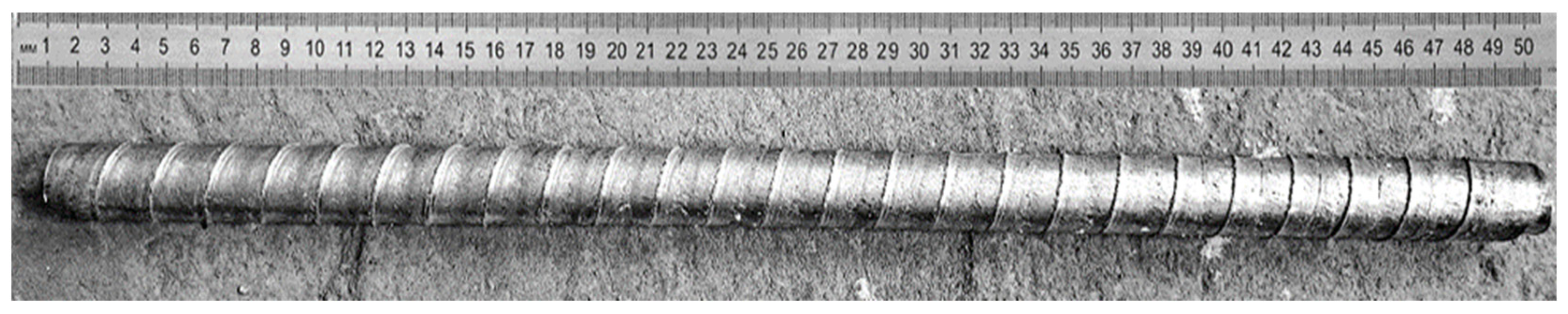
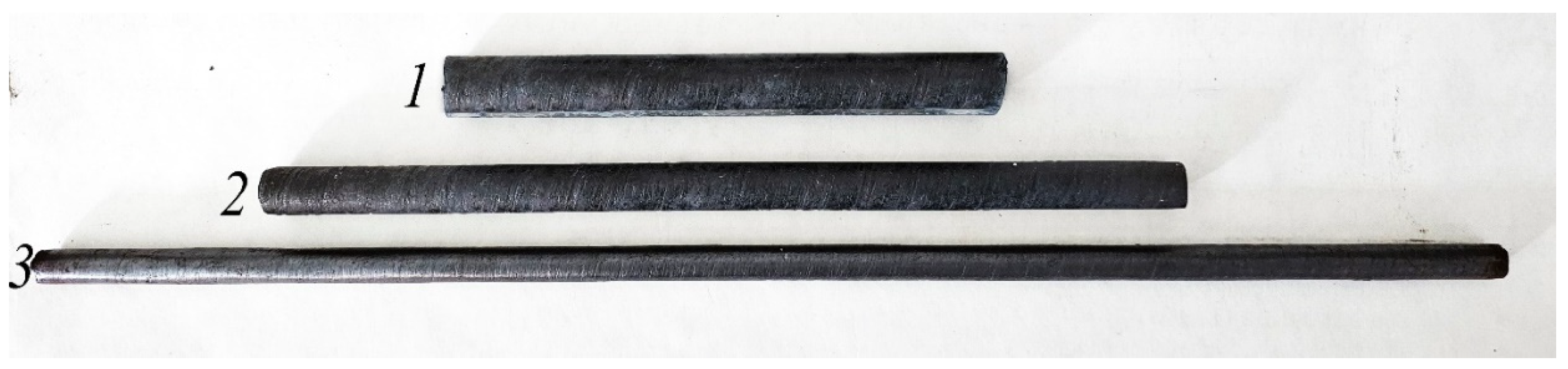
  • A completely new technology of combined deformation has been developed, which makes it possible to produce steel bars with enhanced strength and plastic characteristics. This technology consists of drawing medium carbon steel bars on a radial-displacement rolling mill and subsequent drawing.
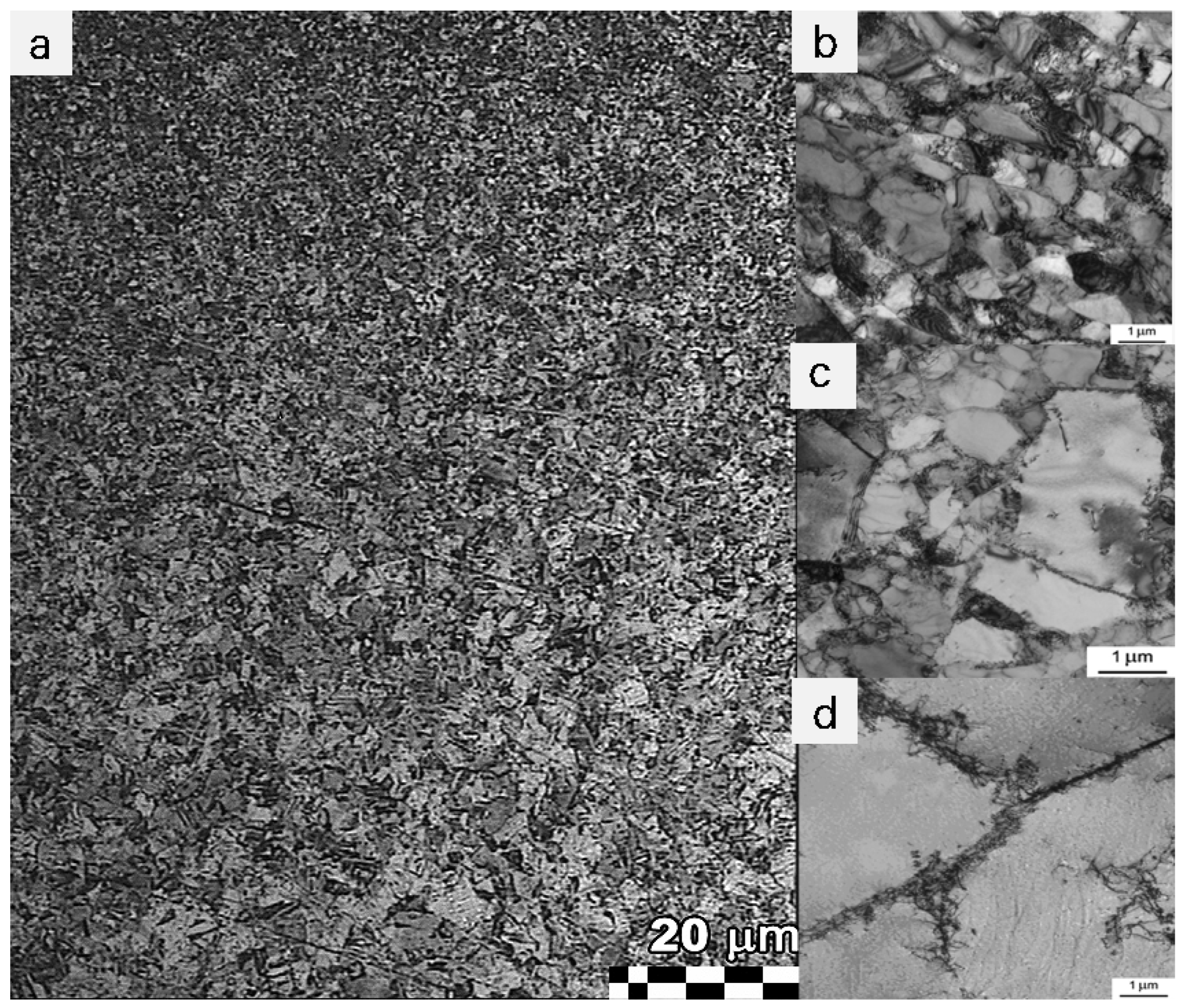
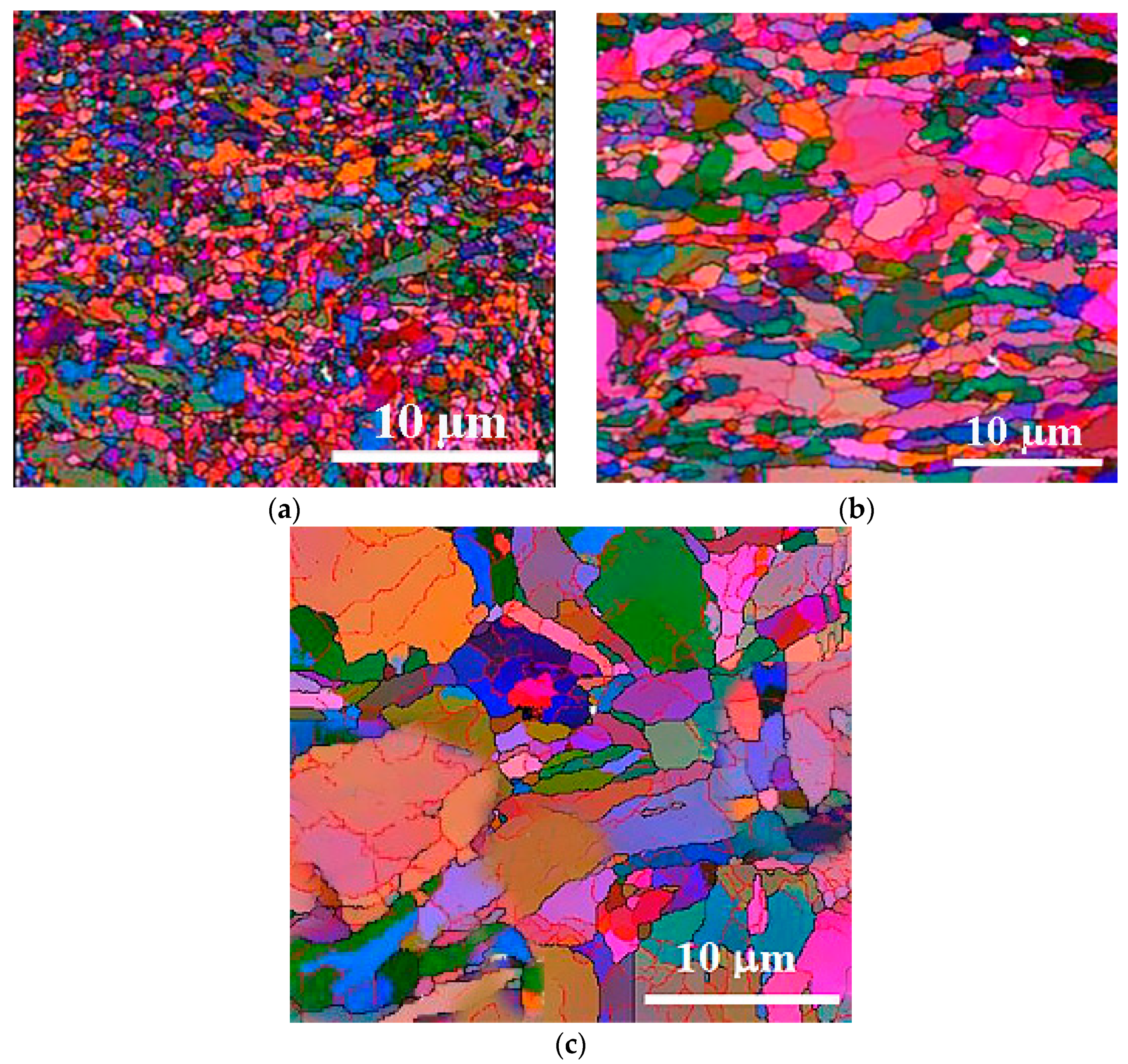
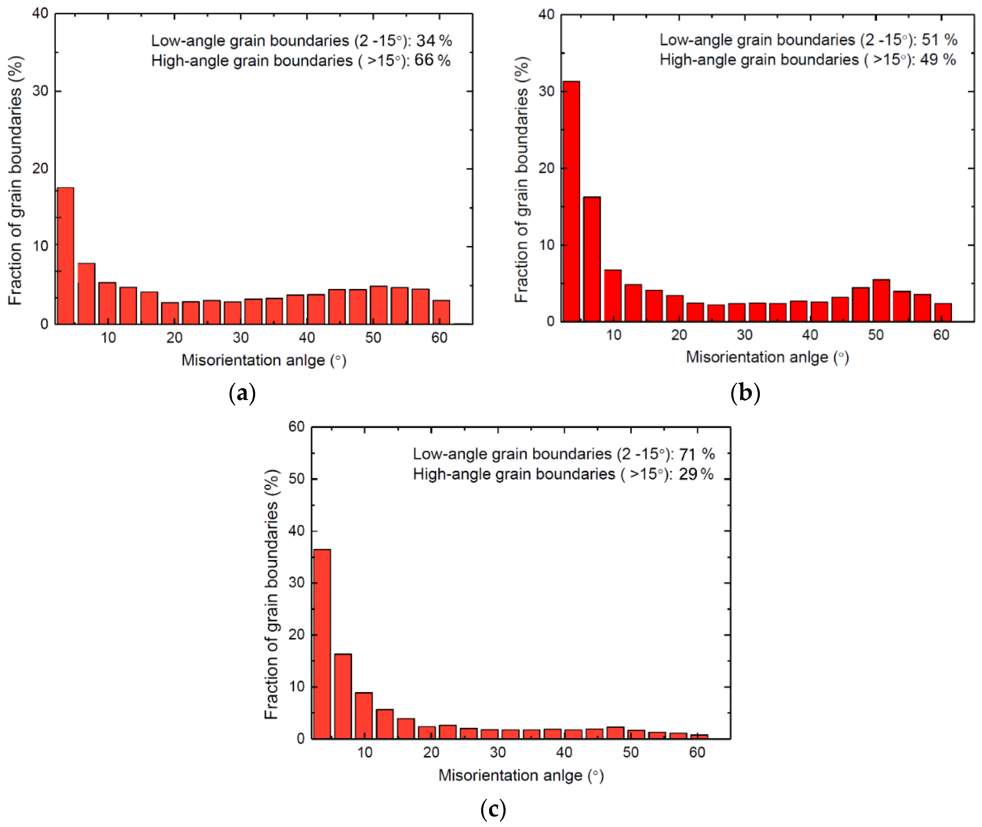
  • The deformation resulted in bars with gradient microstructure. The surface area of the bar is significantly ground; the average ferrite size is 0.5 µm. The deformation is not large enough in the neutral zone, so the structure is not so as strongly refined. Ferrite grains are reduced to 2 µm. In the central zone, the microstructure is composed of large grains with an average size of 7 µm.
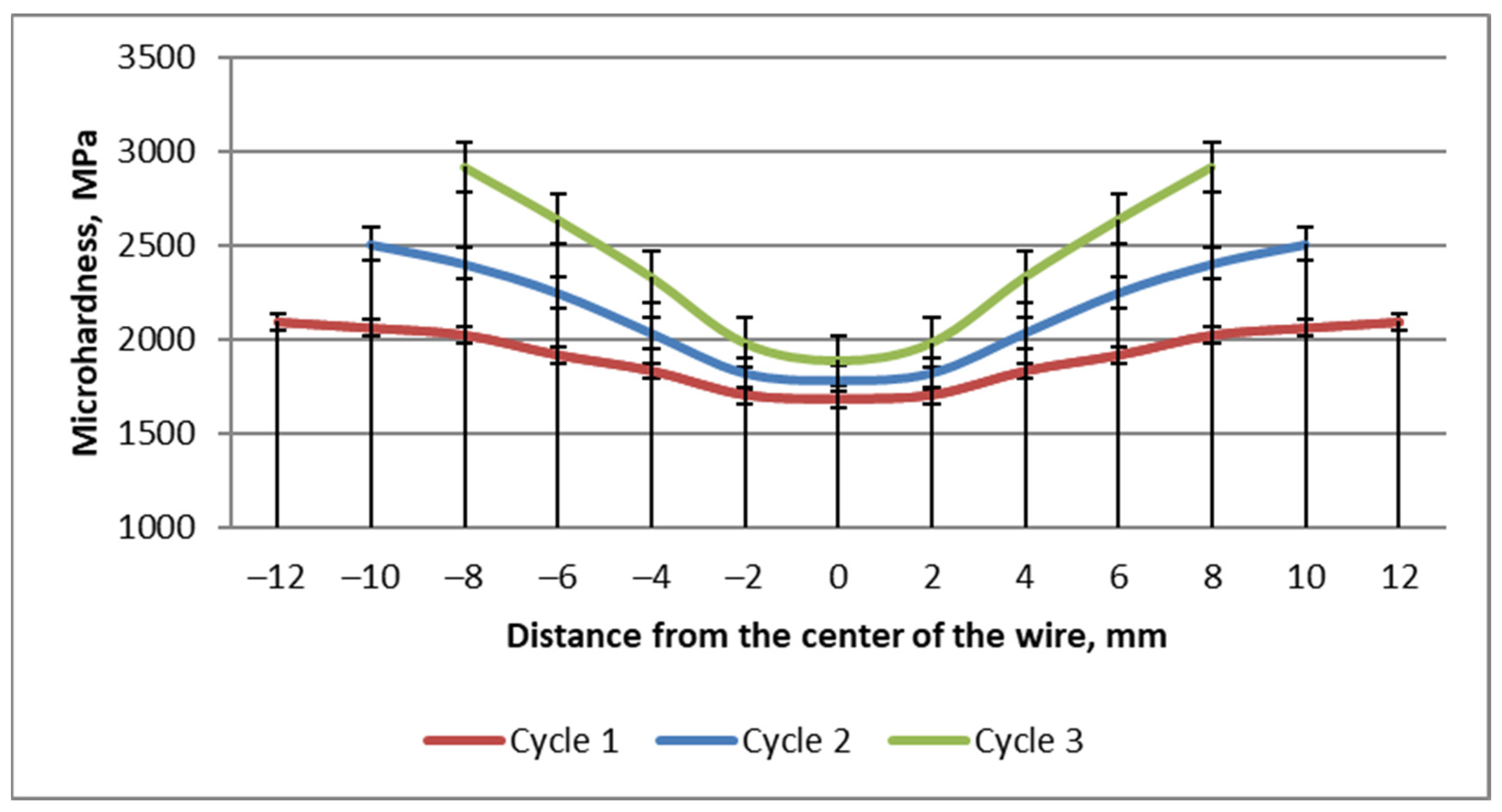
  • The initial microhardness of carbon steel bars was 1515 MPa throughout their entire circumference. Microhardness was 2920 MPa in the surface zone, 2335 MPa in the neutral zone and 1890 MPa in the center of the bar after deformation by RSB-drawing method, and the diameter decreased from 30 mm to 17 mm. This symmetrical spread of the microhardness confirms the gradient microstructure.
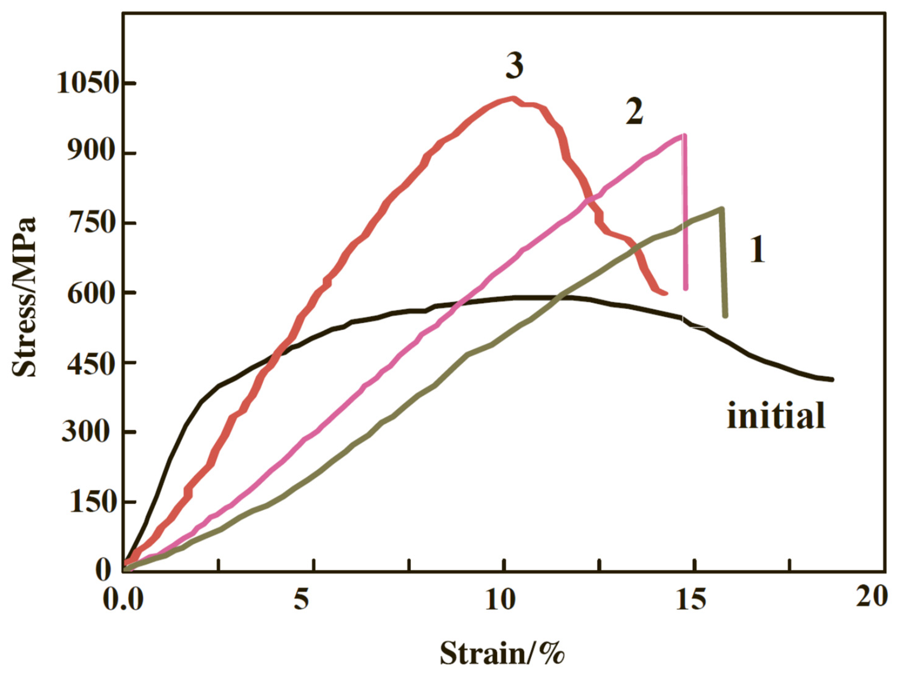
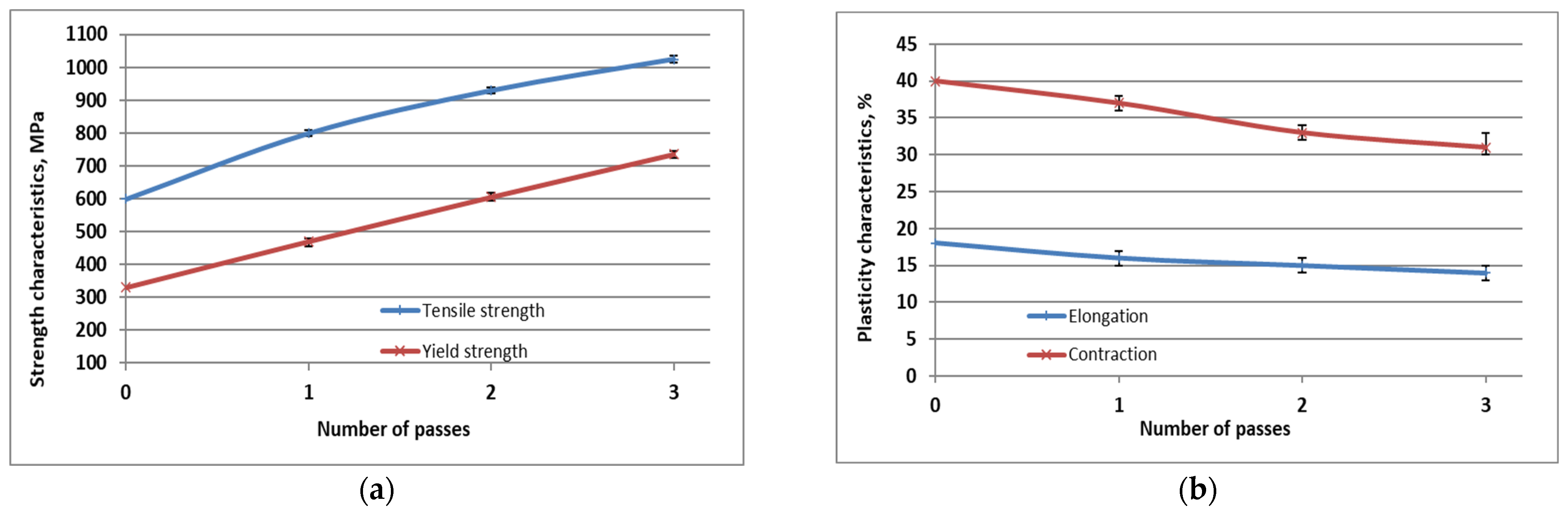
  • After three cycles of deformation in the surface zone, the ultimate strength increased by 70%, and the yield strength increased by 123%. Relative reduction and elongation decreased by 22%. Despite a decrease in plasticity, its values remain at a relatively high level.
  • The obtained results outcomes attest to the efficiency of the proposed technique of combining radial-shift broaching and drawing to produce long bars with enhanced mechanical properties. It is possible to obtain the required physical and mechanical properties of materials by controlling the process of symmetry of such a structure. This method can be successfully applied to various industries where the production of high-quality and reliable materials is required.

Author Contributions

Conceptualization, I.V. and A.V.; methodology, I.V.; investigation, I.V. and A.V.; data curation, B.M.; writing—original draft preparation, I.V. and A.V.; writing—review and editing, I.V., A.V. and B.M.; supervision, I.V. and A.V.; project administration, B.M.; funding acquisition, B.M. All authors have read and agreed to the published version of the manuscript.

Funding

This research has been/was/is funded by the Science Committee of the Ministry of Science and Higher Education of the Republic of Kazakhstan (Grant No. AP19678974).

Data Availability Statement

Data are contained within the article.

Conflicts of Interest

The authors declare no conflicts of interest.

References

  1. Sherov, K.; Serova, R.; Yessirkepova, A.; Mussayev, M.; Zhanakov, K.; Smailova, B.; Turusbekova, A.; Mazhitova, L. Enhancing the efficiency of rebar use in reinforced concrete products’ manufacturing. IOP Conf. Ser. Mater. Sci. Eng. 2021, 1047, 012025. [Google Scholar] [CrossRef]
  2. Neamat, S.; Shamsborhan, M. The Investigation of The Different Types of the Ground Rebar Spacers with Proposing New Design Rebar Space Mixed of Concrete Palstic. J. Civ. Eng. Front. 2020, 1, 1–6. [Google Scholar] [CrossRef]
  3. Lezhnev, S.; Naizabekov, A.; Panin, E. Radial-shear rolling as a new technological solution for recycling bar scrap of ferrous metals. Mater. Sci. Forum 2022, 1052, 498–503. [Google Scholar] [CrossRef]
  4. Volokitina, I.; Volokitin, A.; Panin, E. Gradient microstructure formation in carbon steel bars. J. Mater. Res. Technol. 2024, 31, 2985–2993. [Google Scholar] [CrossRef]
  5. Skripalenko, M.M.; Romantsev, B.A.; Galkin, S.P.; Skripalenko, M.N.; Kaputkina, L.M.; Huy, T.B. Prediction of the Fracture of Metal in the Process of Screw Rolling in a Two-Roll Mill. Metallurgist 2018, 61, 925–933. [Google Scholar] [CrossRef]
  6. Naizabekov, A.; Panin, E. Structure and mechanical properties of steel in the process “pressing-drawing”. J. Mater. Eng. Perform. 2019, 28, 1762–1771. [Google Scholar] [CrossRef]
  7. Snopiński, P. Electron Microscopy Study of Structural Defects Formed in Additively Manufactured AlSi10Mg Alloy Processed by Equal Channel Angular Pressing. Symmetry 2023, 15, 860. [Google Scholar] [CrossRef]
  8. Xu, J.; Li, J.; Shan, D.; Guo, B. Microstructural evolution and micro/meso-deformation behavior in pure copper processed by equal-channel angular pressing. Mater. Sci. Eng. A 2016, 664, 114–125. [Google Scholar] [CrossRef]
  9. Latypova, M.A.; Chigirinsky, V.V.; Kolesnikov, A.S. Effect of Controlled Rolling on the Structural and Phase Transformations. Prog. Phys. Met. 2023, 24, 132–156. [Google Scholar] [CrossRef]
  10. Segal, V.M. Materials processing by simple shear. Mater. Sci. Eng. A 1995, 197, 157–164. [Google Scholar] [CrossRef]
  11. Dao, M.; Lu, L.; Asaro, R.; De Hosson, J.T.M.; Ma, E. Toward a quantitative understanding of mechanical behavior of nanocrystalline metals. Acta Mater. 2007, 55, 4041–4065. [Google Scholar] [CrossRef]
  12. Mythili, R.; Kirana, R.; Herojit Singh, L.; Govindaraj, R.; Sinha, A.; Singh, M.; Saroja, S.; Vijayalakshmi, M.; Deb, S. Identification of Retained Austenite in 9Cr-1.4W-0.06Ta-0.12C Reduced Activation Ferritic Martensitic Steel. Symmetry 2022, 14, 196. [Google Scholar] [CrossRef]
  13. Muszka, K.; Zych, D.; Lisiecka-Graca, P.; Madej, L.; Majta, J. Experimental and Molecular Dynamic Study of Grain Refinement and Dislocation Substructure Evolution in HSLA and IF Steels after Severe Plastic Deformation. Metals 2020, 10, 1122. [Google Scholar] [CrossRef]
  14. Bychkov, A.; Volokitin, A.; Kolesnikov, A. Natural Aging of Aluminum Alloy 2024 After Severe Plastic Deformation. Metallogr. Microstruct. Anal. 2023, 12, 564–566. [Google Scholar] [CrossRef]
  15. Vasilyeva, N.; Fedorova, E.; Kolesnikov, A. Big Data as a Tool for Building a Predictive Model of Mill Roll Wear. Symmetry 2021, 13, 859. [Google Scholar] [CrossRef]
  16. Sapargaliyeva, B.; Agabekova, A.; Syrlybekkyzy, S.; Ulyeva, G.; Yerzhanov, A.; Kozlov, P. Study of changes in microstructure and metal interface Cu/Al during bimetallic construction wire straining. Case Stud. Constr. Mater. 2023, 18, e02162. [Google Scholar] [CrossRef]
  17. Kolesnikov, A.S.; Kolesnikova, O.G. Effect of Deformation by High-Pressure Torsion in a Combined Matrix on the Properties of Brass. Metallurgist 2023, 66, 1601–1606. [Google Scholar] [CrossRef]
  18. Lezhnev, S.; Panin, E. Research of combined process rolling-pressing influence on the microstructure and mechanical properties of aluminium. Adv. Mater. Res. 2013, 814, 68–75. [Google Scholar] [CrossRef]
  19. Murashkin, M.Y.; Sabirov, I.; Kazykhanov, V.U. Enhanced mechanical properties and electrical conductivity in ultrafine-grained Al alloy processed via ECAP-PC. J. Mater. Sci. 2013, 48, 4501–4509. [Google Scholar] [CrossRef]
  20. Chukin, M.V.; Korchunov, A.G.; Polyakova, M.A.; Emaleeva, D.G. Forming ultrafine-grain structure in steel wire by continuous deformation. Steel Transl. 2010, 40, 595–597. [Google Scholar] [CrossRef]
  21. Kurapov, G.; Orlova, E.; Turdaliev, A. Plasticity as a physical-chemical process of deformation of crystalline solids. J. Chem. Technol. Metall. 2016, 51, 451–457. [Google Scholar]
  22. Zhang, X.; Hansen, N.; Gao, Y.; Huang, X. Hall-Petch and dislocation strengthening in graded nanostructured steel. Acta Mater. 2012, 60, 5933–5943. [Google Scholar] [CrossRef]
  23. Wang, K.; Tao, N.R.; Liu, G.; Lu, J.; Lu, K. Plastic strain-induced grain refinement at the nanometer scale in copper. Acta Mater. 2006, 54, 5281–5291. [Google Scholar] [CrossRef]
  24. Li, W.L.; Tao, N.R.; Lu, K. Fabrication of a gradient nano-micro-structured surface layer on bulk copper by means of a surface mechanical grinding treatment. Scripta Mater. 2008, 59, 546–549. [Google Scholar] [CrossRef]
  25. Lezhnev, S.; Koinov, T. Research of influence equal channel angular pressing on the microstructure of copper. J. Chem. Technol. Metall. 2014, 49, 621–630. [Google Scholar]
  26. Nayan, N.; Narayana Murty, S.V.S.; Jha, A.K.; Pant, B.; Sharma, S.C.; George, K.M.; Sastry, G.V.S. Mechanical properties of aluminium-copper-lithium alloy AA2195 at cryogenic temperatures. Mater. Des. 2014, 58, 445–450. [Google Scholar] [CrossRef]
  27. Li, J.; Mei, Q.; Li, Y.; Wang, T. Production of Surface Layer with Gradient Microstructure and Microhardess on Copper by High Pressure Surface Rolling. Metals 2020, 10, 73. [Google Scholar] [CrossRef]
  28. Galkin, S.P. Moscow State Institute of Steel and Alloys. Method of Helical Rolling. Russian Patent No. 2293619, 20 February 2007. (In Russian). [Google Scholar]
  29. Galkin, S.P. Radial shear rolling as an optimal technology for lean production. Steel Transl. 2014, 44, 61–64. [Google Scholar] [CrossRef]
  30. Kharitonov, V.A.; Usanov, M. Study of Radial-Shear Wire Broaching Based on Modelling. Metallurgist 2014, 57, 1015–1021. [Google Scholar] [CrossRef]
  31. Akopyan, T.K.; Gamin, Y.V.; Galkin, S.P.; Prosviryakov, A.S.; Aleshchenko, A.S.; Noshin, M.A.; Koshmin, A.N.; Fomin, A.V. Radial-Shear Rolling of High-Strength Aluminum Alloys: Finite Element Simulation and Analysis of Microstructure and Mechanical Properties. Mater. Sci. Eng. A 2020, 786, 139424. [Google Scholar] [CrossRef]
  32. Karpov, B.V.; Patrin, P.V.; Galkin, S.P.; Kharitonov, E.A.; Karpov, I.B. Radial-Shear Rolling of Titanium Alloy VT-8 Bars with Controlled Structure for Small Diameter Ingots (≤200 mm). Metallurgist 2018, 61, 884–890. [Google Scholar] [CrossRef]
  33. Nurumgaliyev, A.; Zhuniskaliyev, T.; Shevko, V.; Yerekeyeva, G. Modeling and development of technology for smelting a complex alloy (ligature) Fe-Si-Mn-Al from manganese-containing briquettes and high-ash coals. Sci. Rep. 2024, 14, 7456. [Google Scholar] [CrossRef] [PubMed]
  34. Lezhnev, S.; Naizabekov, A.; Kuis, D.; Kasperovich, A.; Panin, E. Modeling of the rebar products recycling technology by radial-shear rolling and drawing. In Proceedings of the METAL 2021—30th Anniversary International Conference on Metallurgy and Materials, Brno, Czech Republic, 26–28 May 2021; pp. 193–198. [Google Scholar] [CrossRef]
  35. Sapargaliyeva, B.; Agabekova, A.; Liseitsev, Y.; Vavrenyuk, S. Increasing strength and performance properties of bimetallic rods during severe plastic deformation. Case Stud. Constr. Mater. 2023, 19, e02256. [Google Scholar] [CrossRef]
  36. Volokitina, I.E.; Volokitin, A.V. Changes in Microstructure and Mechanical Properties of Steel-Copper Wire During Deformation. Metallurgist 2023, 67, 232–239. [Google Scholar] [CrossRef]
  37. Raab, G.I.; Gunderov, D.V.; Shafigullin, L.N.; Podrezov, Y.M.; Danylenko, M.I.; Tsenev, N.K.; Bakhtizin, R.N.; Aleshin, G.N.; Raab, A.G. Structural variations in low-carbon steel under severe plastic deformation by drawing, free torsion, and drawing with shear. Mater. Phys. Mech. 2015, 3, 242–252. [Google Scholar]
  38. Liu, M.; Li, J.Y.; Ma, Y.; Yuan, T.Y.; Mei, Q.S. Surface nanocrystallization and property of Ti6Al4V alloy induced by high pressure surface rolling. Sur. Coat. Tech. 2016, 289, 94–100. [Google Scholar] [CrossRef]
  39. Zeng, Z.; Li, X.; Xu, D.; Lu, L.; Gao, H.; Zhu, T. Gradient plasticity in gradient nano-grained metals. Extrem. Mech. Lett. 2016, 8, 213–219. [Google Scholar] [CrossRef]
  40. Yang, X.; Ling, X.; Wang, D.; Wang, W. Deformation behavior and formability of gradient nano-grained AISI 304 stainless steel processed by ultrasonic impact treatment. J. Wuhan Univ. Technol. Mater. Sci. Ed. 2017, 32, 1147–1155. [Google Scholar] [CrossRef]
  41. GOST 9450-76; Measurement of Microhardness by Indentation of Diamond Tips. GOST: Moscow, Russia, 1976.
  42. GOST 1497-2023; Metals. Tensile Test Methods. RussianGost: Moscow, Russia, 2023.
  43. Naizabekov, A.; Lezhnev, S.; Panin, E.; Koinov, T.; Mazur, I. Effect of Combined Rolling–ECAP on Ultrafine-Grained Structure and Properties in 6063 Al Alloy. J. Mater. Eng. Perform. 2019, 28, 200–210. [Google Scholar] [CrossRef]
  44. Volokitina, I.E.; Volokitin, A.V.; Panin, E.; Fedorova, T.; Lawrinuk, D.; Kolesnikov, A.; Yerzhanov, A.; Gelmanova, Z.; Liseitsev, Y. Improvement of strength and performance properties of copper wire during severe plastic deformation and drawing process. Case Stud. Constr. Mater. 2023, 19, e02609. [Google Scholar] [CrossRef]
  45. Deng, S.Q.; Godfrey, A.; Liu, W.; Zhang, C.L. Microstructural evolution of pure copper subjected to friction sliding deformation at room temperature. Mater. Sci. Eng. A 2015, 639, 448–455. [Google Scholar] [CrossRef]
Figure 1. Combined technology scheme for deforming bars: 1—pulling device, 2—bar, 3—drawing die, 4—rolls of PCP-10/30 mill for broaching.
Symmetry 16 00997 g001
Figure 2. Bar only after radial-shift broaching stage.
Symmetry 16 00997 g002
Figure 3. Bar after each deformation cycle of the combined technology: 1—1st deformation cycle, 2—2nd deformation cycle, 3—3rd deformation cycle.
Symmetry 16 00997 g003
Figure 4. Microstructure of bars after 3 deformation passes (cross section): (a) OM, (b–d) TEM.
Symmetry 16 00997 g004
Figure 5. EBSD analysis of deformed bars: (a) surface zone, (b) neutral zone, (c) central zone.
Symmetry 16 00997 g005
Figure 6. Disorientation angle diagrams: (a) surface zone, (b) neutral zone, (c) central zone.
Symmetry 16 00997 g006
Figure 7. Plots of microhardness distribution after each deformation cycle along the steel bar cross section.
Symmetry 16 00997 g007
Figure 8. Tension diagrams after each deformation cycle: 1—1st deformation cycle, 2—2nd deformation cycle, 3—3rd deformation cycle.
Symmetry 16 00997 g008
Figure 9. Plots of mechanical properties of steel bar depending on the deformation cycle: (a) strength properties; (b) plastic properties.
Symmetry 16 00997 g009
Figure 10. Fractography of the fracture surface: (a) surface zone, (b) neutral zone, (c) central zone.
Symmetry 16 00997 g010
Table 1. AISI 1045 steel chemical composition.
ElementCSiMnNiCrCuFe
Mass fraction, %0.450.170.80.20.150.15rest
Table 2. Deformation modes.
Radial-Shift BroachingDrawing
No. of PassD1, mmD2, mmV2, m/sV1, m/sε, %εlnD2, mmD3, mmV3, m/sV2, m/sε, %εln
1 pass30.025.00.0140.0130.560.3625.023.00.0170.01415.360.17
2 pass23.020.00.0130.0124.390.2820.019.00.0150.0139.750.10
3 pass19.017.00.0120.0119.940.2217.016.00.0140.01211.420.12
εΣ, %67.89εlnΣ0.87 εΣ, %59.04εlnΣ0.39
εln(total) = 1.52
Disclaimer/Publisher’s Note: The statements, opinions and data contained in all publications are solely those of the individual author(s) and contributor(s) and not of MDPI and/or the editor(s). MDPI and/or the editor(s) disclaim responsibility for any injury to people or property resulting from any ideas, methods, instructions or products referred to in the content.

