Article

One-Cycle Control with Composite Function Embedded for Boost Converters

1
School of Shipping and Maritime Studies, Guangzhou Maritime University, Guangzhou 510725, China
2
School of Electronic and Electrical Engineering, Chongqing University of Science and Technology, Chongqing 401331, China
*
Author to whom correspondence should be addressed.
Symmetry 2025, 17(4), 559; https://doi.org/10.3390/sym17040559
Submission received: 18 January 2025 / Revised: 14 March 2025 / Accepted: 4 April 2025 / Published: 7 April 2025

Abstract

:
It has been confirmed that a larger stability domain has more advantages for system operation. In this paper, a novel one-cycle control (OCC) embedded with a composite function is proposed. Its control principle is based on maintaining the symmetry of the volt-second value for the inductor in each cycle. Then, selecting the reference voltage as the study variable, the stability boundaries and identify stable parameter domains are studied by establishing a state-space average model. The results demonstrate that, compared with the conventional OCC, the proposed OCC with composite function u embedded achieves an expanded stable parameter domain, effectively delaying the occurrence of instability phenomena from u r e f = 2 u i n to u r e f = 3 u i n . Both the simulation and experimental results conclusively validate the theoretical analysis, confirming the effectiveness and superiority of the proposed control strategy.

1. Introduction

As a power electronic converter, boost converters have been widely used in many fields, such as new energy generation, computer power supply, and automotive electronic system [1,2,3]. Power electronic converters are highly nonlinear systems, so they are prone to exhibit bifurcation, oscillation, chaos, and many other nonlinear behaviors, which cause the system to be unstable. Various existing linear or non-linear control methods, such as current-mode control, adaptive feedback control, bang-bang control, sliding Mode Control, model predictive control (MPC), and one-cycle control (OCC), present different non-linear characteristics and stable parameter domains [4,5,6,7,8,9,10].
However, the stability of the system is essential for normal operation. In fact, the stability of the system is closely related to the control strategy adopted by the system. Thus, many existing control methods have been improved and various non-linear control strategies have been proposed for improving stability. For controlling chaos, the Ott-Grebogi−Yorke (OGY) method has been proposed, but it is difficult to implement [11]. Time-delay feedback control (TDF) has been proposed for improving non-linear characteristics in power electronic converters, which is an effective and popular method, but its delay signal is difficult to produce [12,13]. To avoid these problems, filters have been added to the control strategy for improving the stability of the system; however, the addition of filters often increases the control parameters that need to be determined [14,15]. This leads to greater computational complexity. Further, the resonant parametric perturbation involving non-feedback control confirms that it is able to control the non-linear phenomena in DC−DC converters. The challenge when using this method is that some parameters must be perturbed at appropriate frequencies and amplitudes [16].
Recently, the energy balance control (EBC) strategy has been proposed, which has proven to effectively extend the stable parameter domain of the systems, while avoiding unstable behaviors such as Hopf bifurcation, oscillation, and even chaos [17,18]. By building the sample-data model, the CFOCC method has been verified to have the ability to eliminate the bifurcation of the OCC buck-boost converter [19].
In summary, the majority of stable domain expansion methods used at present have issues such as difficulty determining feedback signals and control parameters as well as increasing the system order. Thus, this paper presents a novel one-cycle control with a composite function embedded. The contributions of this article are as follows: (1) By embedding the composite function, the distribution of the system eigenvalues in the complex plane is changed, then the non-linear stability performance of the OCC boost converter is improved by delaying the appearance of the bifurcation point. (2) The change in distribution of the system eigenvalues enlarges the stable region. (3) The embedding of the function does not increase the order of the system, and thus does not increase the computational complexity. Based on the symmetry concept, the control of the converters is implemented by keeping the balance of absorbing and releasing electrical energy in each cycle. The paper is organized as follows: in Section 2, the average model of a boost converter and stability analysis of the conventional OCC boost converter are discussed. In Section 3, the converter with the proposed OCC with the composite function embedded is introduced and its stability is analyzed using an average model. The proposed method and the non-linear stability theoretical analysis are confirmed through calculations, simulations, and experiments in Section 4 and Section 5. Section 6 concludes this article.

2. The Average Model of a Boost Converter and Stability Analysis of the Conventional OCC Boost Converter

This section presents a comparative stability analysis stability of the boost converter using the average modes of both the conventional OCC and the proposed OCC with the embedded composite function. First, the average model of a boost converter is built, then the working principle and average model of a conventional OCC boost converter are derived.

2.1. The Average Model of a Boost Converter

The structure of a boost converter is shown in Figure 1, where i represents the current of the inductor, ic represents the current across the capacitor, io represents the current of the load, u represents the output voltage, and Ts is the switching cycle.
Under the CCM operation mode, the boost converter operates in two states: state 1 where S is in the on-state, state 2 where S is in the off-state. Thus, according to [20], this boost converter is described as follows:
d i d t = u i n L 1 s L u d u d t = u R C + i 1 s C
where s = 1 denotes that S is in the on-state and s = 0 denotes that S is in the off-state [20].

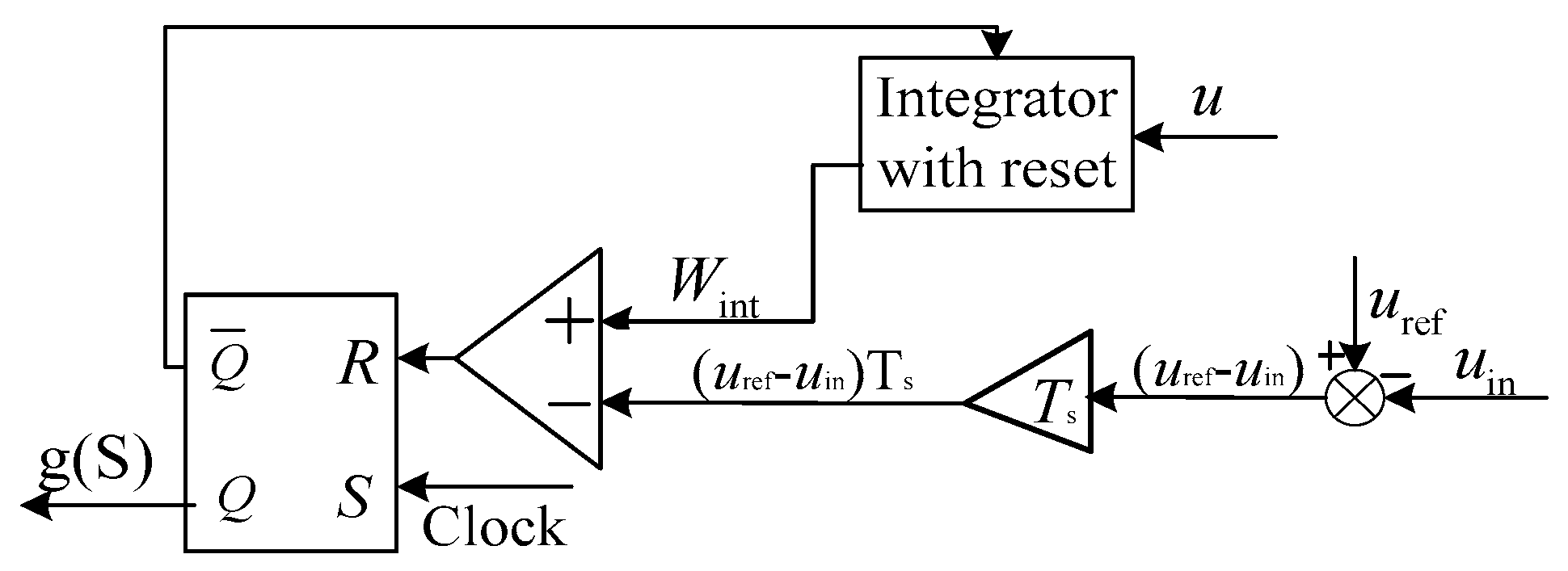
2.2. The Stability Analysis of the OCC Boost Converter

To analyze the stability of a conventional OCC boost converter, its average model is derived according to [20]. As shown in Figure 2, the control equation of the OCC boost converter is obtained as follows:
( n 1 ) T s ( n 1 ) T s + t o n ( n ) u d t = ( u r e f u i n ) T s
Then, the average model of (2) can be obtained as follows:
u d = u r e f u i n
where d, which can be expressed as T o n ( n ) T s , represents the duty ratio of the boost converter.
From (3), d can be derived as follows:
d = u r e f u i n u
Replacing s in (1) with d derived in (4), the average state space model of the conventional OCC boost converter is deduced as
d i d t = u i n L u L [ 1 u r e f u i n u ] , d u d t = u R C + i C [ 1 u r e f u i n u ]
Setting d i d t and d u d t in (5) to be 0, the value of u and i can be derived from (5); here, u = V + u ~ , i = I + 𝚤 ~ . The equilibrium point needs to be derived; during the calculation, u ~ and 𝚤 ~ are ignored when d i d t and d u d t in (5) are set to be 0, thus the equilibrium point can be expressed using only V and I , as follows:
V = u r e f I = u r e f 2 u i n R
At this equilibrium point, the Jacobian matrix can be obtained as follows.
J = 0 1 L V u r e f + u i n C V 1 R C + I ( u r e f u i n ) C V 2
Substituting (6) into the Jacobian matrix (7) obtains
J = 0 1 L u i n C u r e f ( u r e f 2 u i n ) C R u i n
According to det[λIJ] = 0,where I is a 2 × 2 unity matrix, the characteristic equation is derived as follows:
f ( λ ) = λ 2 + [ ( u r e f 2 u i n ) C R u i n ] λ + u i n L C u r e f
To obtain the closed-form expression of the stability of the converter, (9) is rewritten according to the second-order Padé approximation as follows:
a 2 λ 2 + a 1 λ + a 0
where a 2 = 1 , a 1 = ( u r e f 2 u i n ) C R u i n and a 0 = u i n L C u r e f .
According to the Routh criterion, the stable condition of the system is when all roots are on the left side of the complex plane, which means that all a i are positive for a second-degree polynomial. Here, it can be seen that if u r e f < 2 u i n , then a 0 > 0, a 1 > 0, and a 2 > 0 are obtained. Thus, the sufficient and necessary condition for the stability of the OCC boost converter is u r e f < 2 u i n .

3. Stability Analysis of the Boost Converter Using the Proposed OCC with Composite Function Embedded

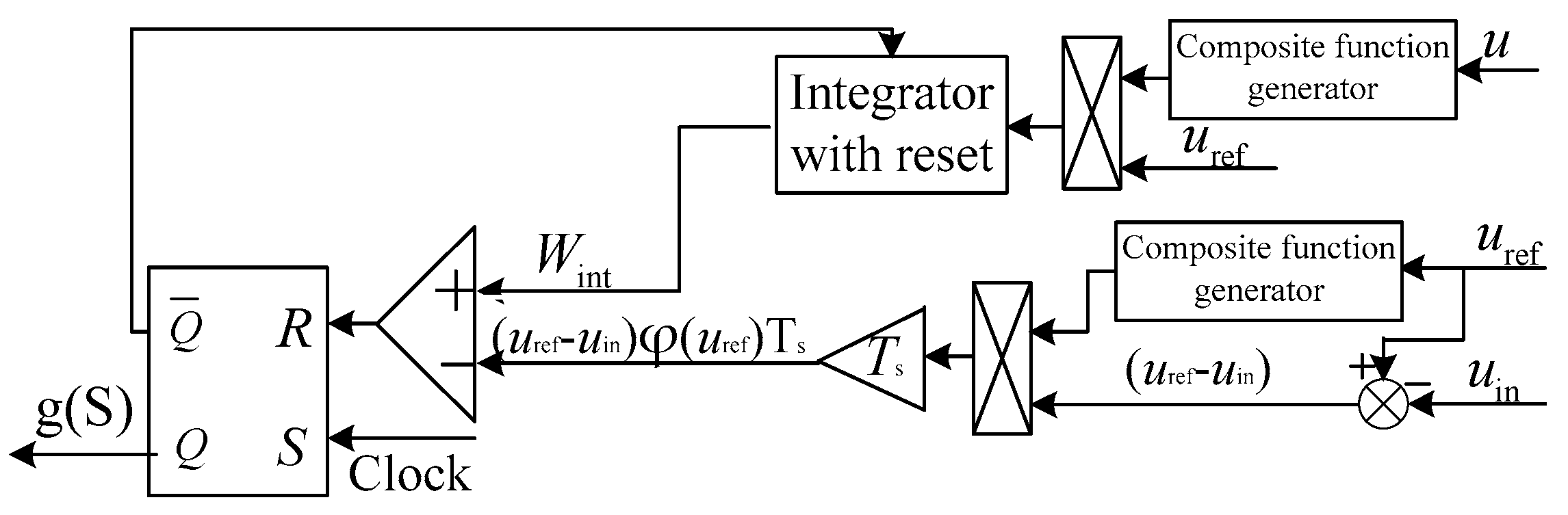
3.1. The Working Principle and Average Model of the Boost Converter Using the Proposed OCC with the Composite Function Embedded

It is known that under fixed circuit parameters, the control principle affects the stability. Thus, based on the conventional OCC, we aimed to embed a composite function in order to change the eigenvalues of the system. The structure of the proposed OCC with the composite function embedded is shown in Figure 3. The structure shows that it is also constituted by a reset integrator, a comparator, and an RS flip-flop but with a composite function.
With the composite function, the control equation of the proposed OCC is written as follows:
( n 1 ) T s ( n 1 ) T s + t o n ( n ) u r e f φ ( u ) d t = ( u r e f u i n ) φ ( u r e f ) T s
where φ ( u ) = u u r e f .
From (10), it can be found that, when φ(u) is a positive strictly increasing function, the system can converge at the equilibrium point in the same way as (2). Here, φ(u) is chosen as φ ( u ) = u . Then, (10) is rewritten as (11):
( n 1 ) T s ( n 1 ) T s + t o n ( n ) u r e f u d t = ( u r e f u i n ) u r e f T s
Then, the average model of (11) is obtained as follows:
u r e f u d = ( u r e f u i n ) u r e f
And d is derived as follows:
d = ( u r e f u i n ) u r e f u r e f u
Replacing s in (1) with d derived in (13), the average state space model of the boost converter for the OCC with the composite function embedded is derived as
d i d t = u i n L u L [ 1 ( u r e f u i n ) u r e f u r e f u ] d u d t = u R C + i C [ 1 ( u r e f u i n ) u r e f u r e f u ]  

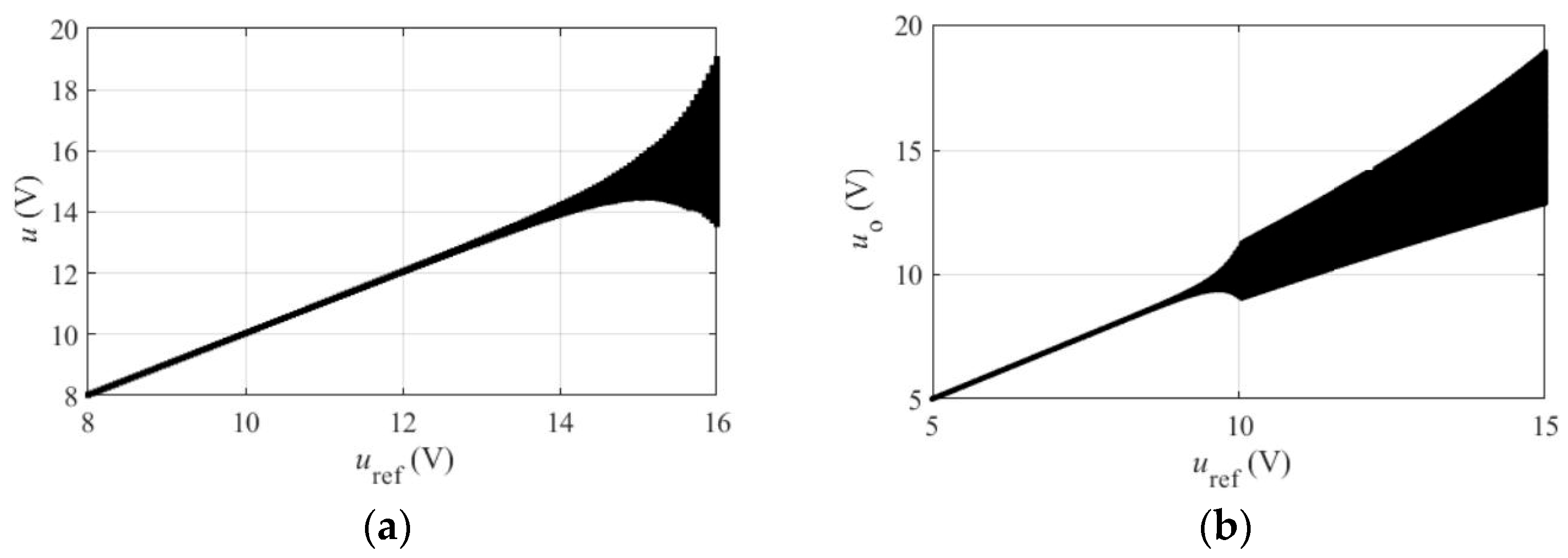
3.2. The Stability Analysis of the Proposed OCC Boost Converter

Setting d i d t and d u d t in (14) to be 0, the equilibrium point can be obtained as follows:
V = u r e f I = u r e f 2 u i n R
Then, the Jacobian matrix evaluated at the equilibrium point is obtained as follows:
J = 0 1 L u r e f u i n 2 L u u r e f 1 C 1 u r e f u i n u r e f u 1 R C + I ( u r e f u i n ) 2 C u u r e f u
Substituting (15) into the Jacobian matrix obtains
J = 0 1 L u r e f u i n 2 L u r e f u i n C u r e f 1 R C + u r e f u i n 2 R C u i n
According to det[λIJ] = 0 and the second-order Padé approximation, the characteristic quasi-polynomial equation can be written as follows:
a 2 λ 2 + a 1 λ + a 0
where a 2 = 1 , a 1 = 3 u i n u r e f 2 R C u i n and a 0 = [ 1 L + ( u r e f u i n ) 2 L u r e f ] u i n C u r e f .
From (18), it is obvious that a 2 > 0 and a 0 > 0 . Here, it can be seen that if u r e f < 3 u i n is satisfied, then a 1 > 0 is obtained. Compared with the stability condition of the conventional OCC, it can be seen that the unstable behavior is delayed; thus, the stable parameter domain is extended by embedding function φ ( u ) , which is chosen as u here.

4. Calculation Verification

The previous sections present the theoretical analysis of the stability of the boost converter using both the proposed OCC with a composite function embedded and the conventional OCC described in the previous section. To verify the results of the above theoretical analysis, take u r e f as the variable parameter, and its characteristic roots can be calculated using the circuit parameters listed in Table 1. These circuit parameters are set based on the laboratory verification. Figure 4 shows the bifurcation diagram of the proposed OCC with the composite function u embedded and the conventional OCC. Figure 4a shows the bifurcation diagram of the proposed OCC with composite function u embedded, as the reference voltage u r e f varies from 8 V to 16 V. From the results, it can be seen that the boost converter with the proposed OCC with the composite function embedded loses its stability when u r e f increases to approximately 15 V. In contrast, Figure 4b shows that when varying u r e f from 5 V to 15 V for the conventional OCC, the boost converter with the conventional OCC losses its stability when u r e f is greater than approximately 10 V. This comparison shows that, compared with the conventional OCC, the proposed OCC with composite function u embedded has a wider stability domain parameter.

5. Simulation and Experimental Verification

To verify the theoretical analysis and the calculation results for the stability of the boost converter in the previous section, according the circuit parameters listed in Table 1, the dynamic stability of the boost converter is tested in simulations and experiments under varying u r e f . Figure 5 and Figure 6 display the simulation results. Figure 7 displays the experimental setup and Figure 8 and Figure 9 display the experimental results.

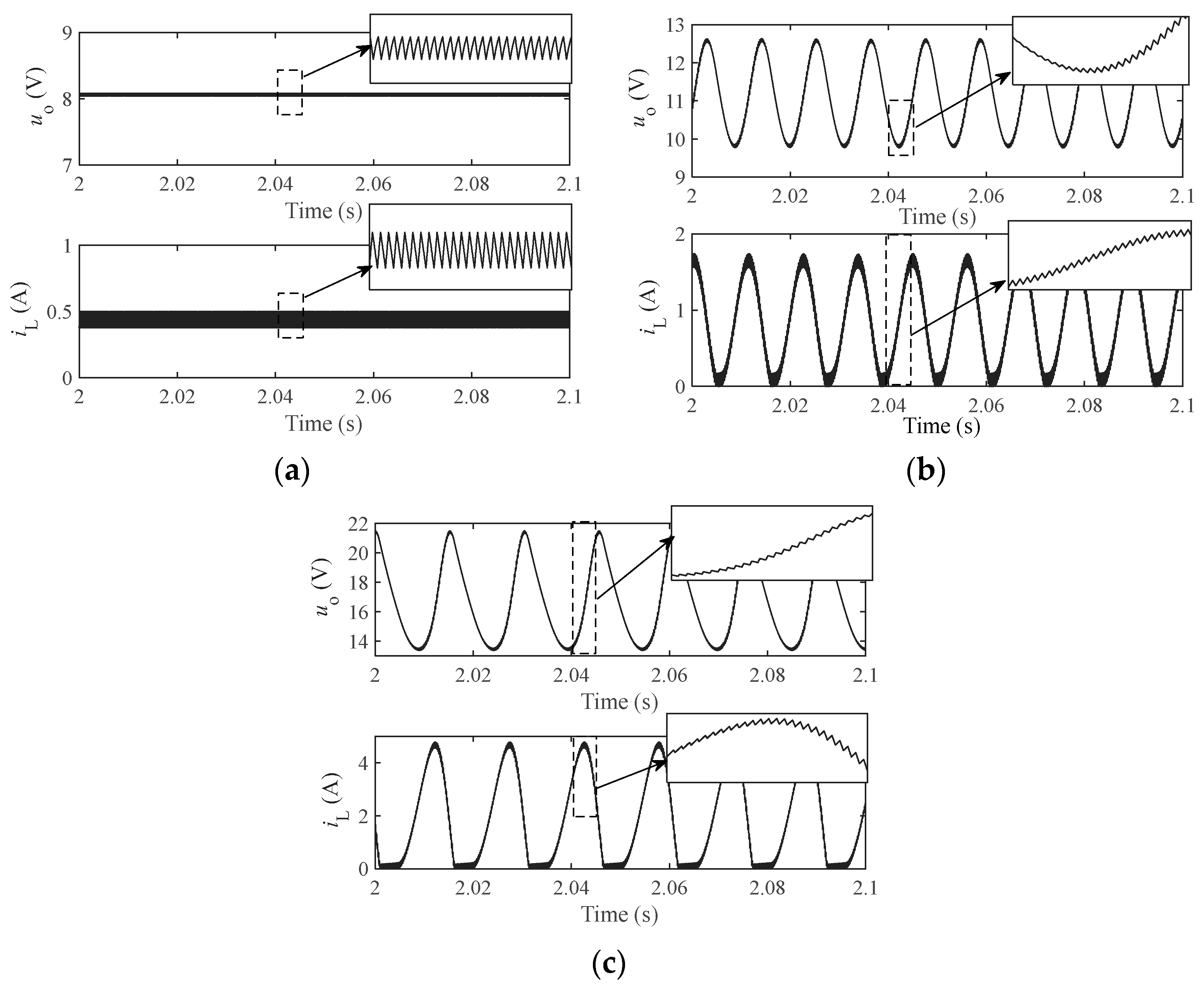
5.1. The Simulation Results

Based on the parameters listed in Table 1, a boost converter is built using Matlab Simulink. Figure 5 and Figure 6 display the results of the boost converter with the proposed OCC, with u embedded and the conventional OCC, respectively. From Figure 5a,b, it can be seen that, under u r e f = 8 V and u r e f = 11 V, the boost converter can operate in a stable manner, and no bifurcation or other non-linear phenomena occur. Figure 5c shows that bifurcation occurs in the boost converter under u r e f = 16 V, which means that the boost converter system using the proposed OCC with u embedded loses its stability.
Figure 6 displays the simulation results of the boost converter with the conventional OCC. The results show that, under u r e f = 8 V, the boost converter can maintain stable operation without any bifurcation or other nonlinear phenomena, as shown in Figure 6a. But, Figure 6b shows that bifurcation occurs in the boost converter under u r e f = 11 V, and with the increase in u r e f , bifurcation becomes increasingly severe, and if u r e f continues to grow, other nonlinear phenomena will even cause chaos. The results show that the simulation results are consistent with the calculation results.

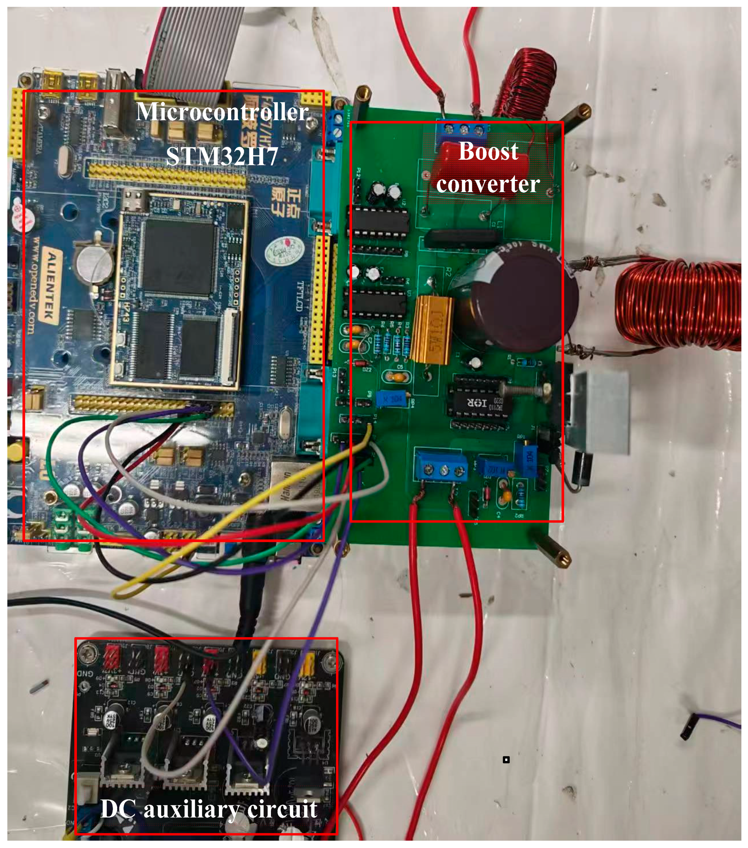
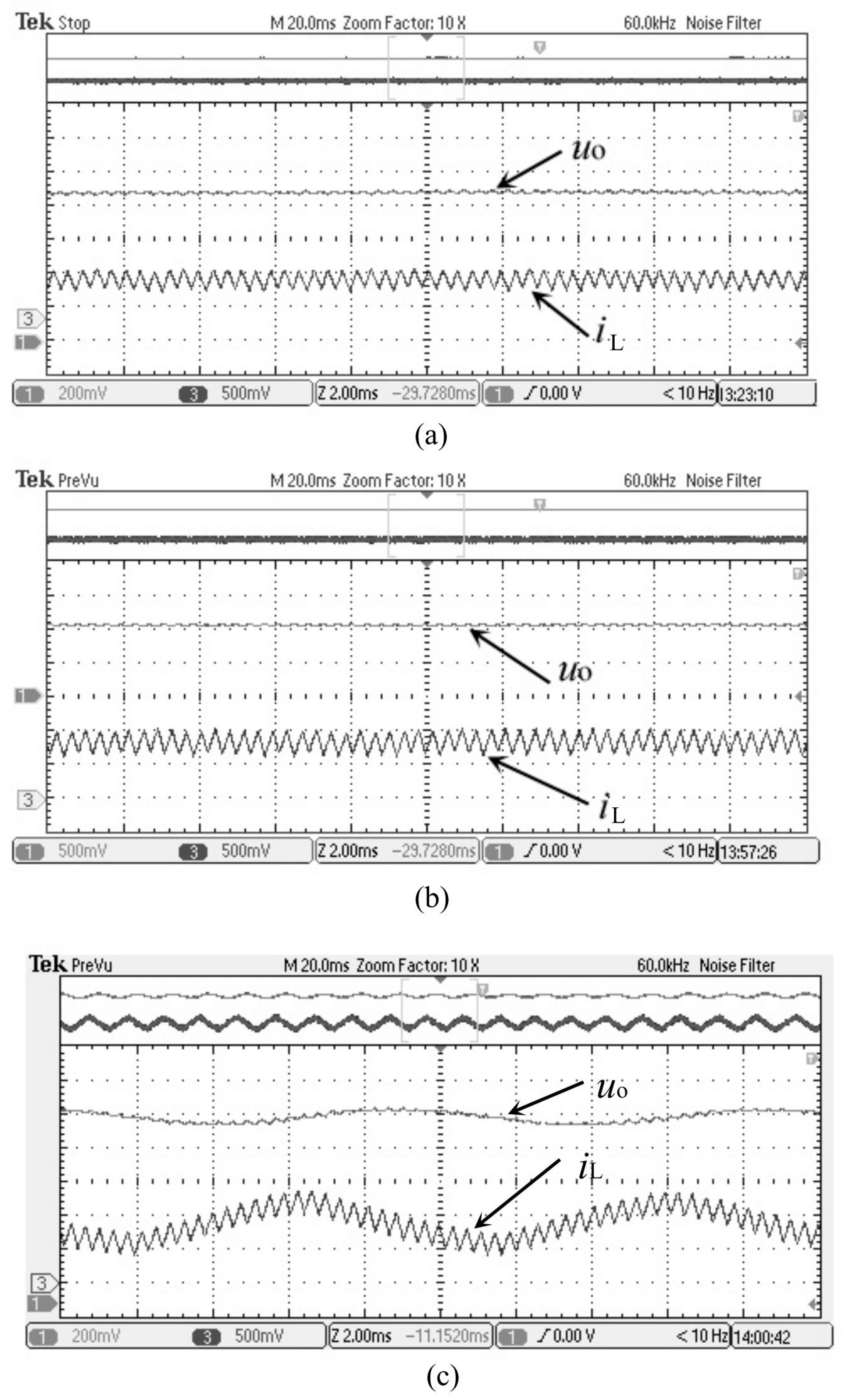
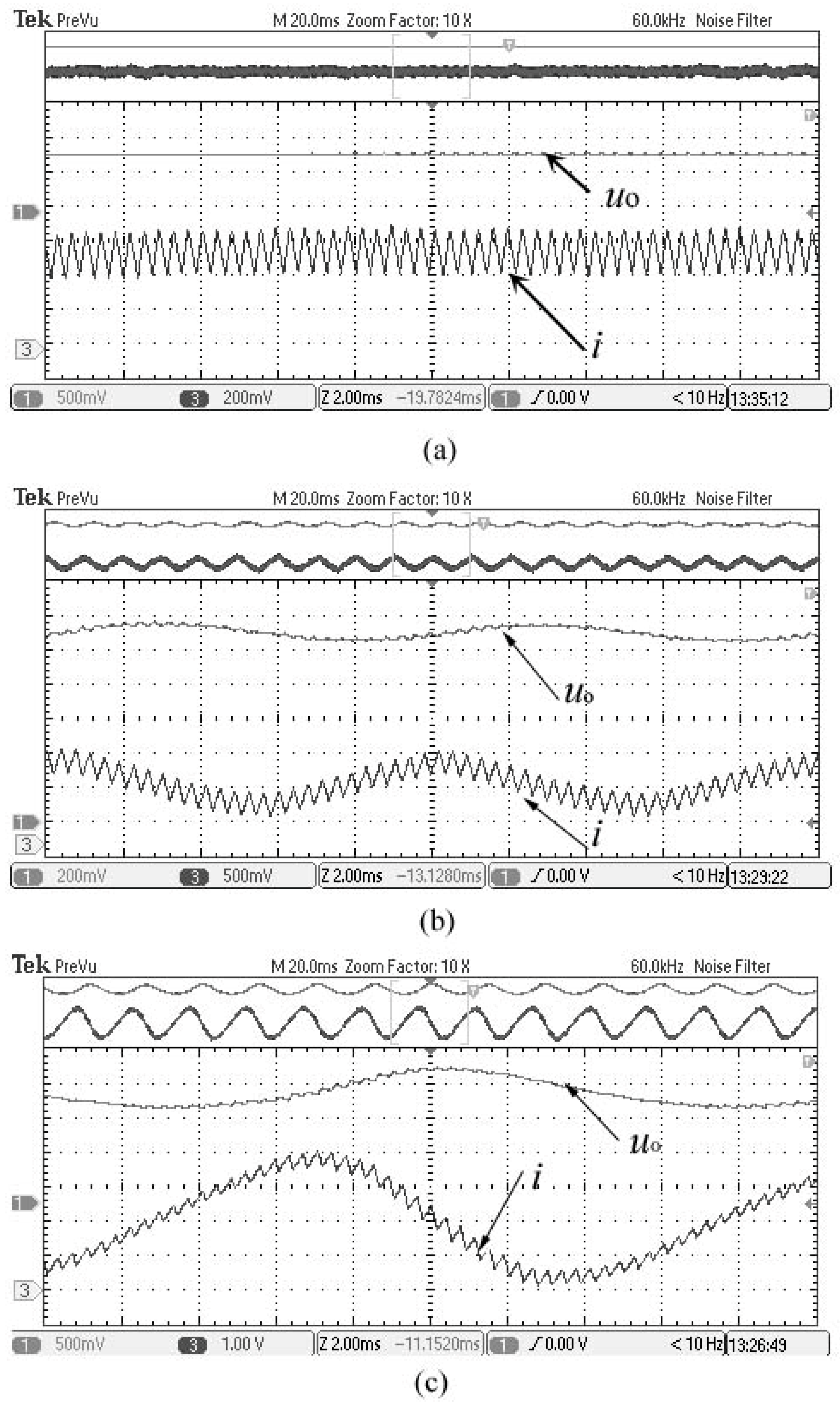
5.2. The Experimental Results

Based on the parameters listed in Table 1 a boost converter is built. The experimental prototype and control platform are shown in Figure 7. A MOSFET switch IRF640N and fast recovery diode BYW29-200 are used for the boost converter experimental prototype. The control is implemented with a Micro controller STM32H7.
The experimental results are shown in Figure 8 and Figure 9. From the results, it can be seen that the experimental results are consistent with the simulation results. Using the proposed OCC with composite function u embedded, the boost converter can maintain stable operation under u r e f = 8 V and u r e f = 11 V, and no bifurcation or other non-linear phenomena occur, as shown in Figure 8a,b. When   u r e f increases to 15 V, bifurcation occurs in the boost converter, just like under u r e f = 16 V, as shown in Figure 8c. As shown in Figure 9, using the conventional OCC, the boost converter works in a stable manner under u r e f = 8 V; however, when   u r e f increases into about 10 V, bifurcation occurs in the boost converter, just like under u r e f = 11 V, as shown in Figure 9b. Obviously, the converter is no longer stable. Further, bifurcation becomes more severe when   u r e f continues to increase, as shown in Figure 9c. From Figure 9c, it can be seen that output voltage oscillates.
Table 2 shows the comparison results of the boost converter with the conventional OCC and the proposed OCC with u embedded. From these results, it can be seen the simulation and experiment results are mostly in agreement with the theories, whereby the boost converter using the proposed OCC with u embedded has wider stable parameter domains.

6. Conclusions

In this study, a novel OCC is proposed by embedding a composite function into the conventional OCC, thus effectively expanding the stable operating region of the boost converters. First, the state-space averaged models are built and the stability boundary is found. Then, stable parameter domains are obtained by analyzing the Jacobian matrix. Then, simulation and experimental models are developed to validate the theoretical predictions. The comparison of these results to the conventional OCC demonstrate that the incorporation of a square function u as the composite function significantly extends the stable operating range from 2uin to 3uin, which effectively delays the occurrence of instability phenomena, including Hopf bifurcation, double frequency bifurcation, and chaotic behavior.
While the current study specifically employs a square function as the composite element, the proposed control method is not limited to this particular function. In fact, various commonly used functions, such as the logarithmic function and arc-tangent function, can be used as the embedded composite functions. Future research will explore these alternatives in order to select the optimal function. Future research will also explore the comparison with other advanced control strategies, i.e., adaptive OCC, to further verify its advantages.

Author Contributions

Conceptualization, L.W. and L.C.; methodology, L.W.; software, J.L.; validation, L.W., J.L. and W.M.; data curation, L.C.; writing—original draft preparation, L.W.; writing—review and editing, W.M. All authors have read and agreed to the published version of the manuscript.

Funding

This research was funded by the National Natural Science Foundation of China, grant number 62001169, and the Guangzhou 2025 Basic and Applied Basic Research Project, grant number SL2024A04J01736.

Data Availability Statement

No new data were created or analyzed in this study. Data sharing is not applicable to this article.

Conflicts of Interest

The authors declare no conflict of interest.

References

  1. Wang, Z.; Li, C.; Zheng, Z.D. A ZVS three-port DC-DC converter based on coupled inductor for fuel cell vehicle. IEEE Trans. Transp. Electrif. 2024, 10, 10314–10327. [Google Scholar] [CrossRef]
  2. Wang, F.L.; Zou, G.B.; Ding, H.X.; Xu, C.H. High voltage gain three-level DC-DC converter with switched-capacitor technique for DC wind farms. IEEE Trans. Ind. Electron. 2024, 71, 12267–12278. [Google Scholar] [CrossRef]
  3. Ertekin, D.A. High gain switched-inductor-capacitor DC-DC boost converter for photovoltaic-based micro-grid applications. CSEE J. Power Energy Syst. 2024, 10, 2398–2410. [Google Scholar]
  4. Trujillo, S.C.; Candelo-Becerra, J.E.; Hoyos, F.E. Numerical validation of a boost converter controlled by a quasi-sliding mode control technique with bifurcation diagrams. Symmetry 2022, 14, 694. [Google Scholar] [CrossRef]
  5. Jouili, K.; Charfeddine, M.; Alqarni, M. Adaptive feedback control of nonminimum phase boost converter with constant power load. Symmetry 2024, 16, 352. [Google Scholar] [CrossRef]
  6. Hu, W.; Zhang, B.; Yang, R.; Qiu, D.Y. Dynamic behaviours of constant on-time one-cycle controlled boost converter. IET Power Electron. 2018, 11, 160–167. [Google Scholar]
  7. Liu, Y.; Xiahou, K.; Wu, Q.H.; Pang, H.; Tang, G. Robust bang-bang control of disturbed nonlinear systems based on nonlinear observers. CSEE J. Power Energy Syst. 2020, 6, 193–202. [Google Scholar] [CrossRef]
  8. Chen, X.B.; Long, X.L.; Hu, W.; Xie, B.S. Bifurcation and chaos behaviors of Lyapunov function controlled PWM boost converter. Energy Rep. 2021, 7, 163–168. [Google Scholar] [CrossRef]
  9. Yu, X.H.; Yang, Y.M.; Xu, L.B.; Ke, D.L.; Zhang, Z.B.; Wang, F.X. Luenberger disturbance observer-based deadbeat predictive control for interleaved boost converter. Symmetry 2022, 14, 924. [Google Scholar] [CrossRef]
  10. Zheng, F.; Su, M.H.; Liu, B.J.; Liu, W.L. Adaptive virtual inertia control strategy for a grid-connected converter of DC microgrid based on an improved model prediction. Symmetry 2023, 15, 2072. [Google Scholar] [CrossRef]
  11. Zhang, L.; Zhang, Z.; Huang, L. Double Hopf bifurcation of time delayed feedback control for Maglev system. Nonlinear Dyn. 2012, 69, 961–967. [Google Scholar] [CrossRef]
  12. El Aroudi, A.; Orabi, M. Stabilizing technique for AC–DC boost PFC converter based on time delay feedback. IEEE Trans. Circuits Syst. II Exp. Briefs 2010, 57, 56–60. [Google Scholar] [CrossRef]
  13. Iu, H.H.C.; Robert, B. Control of chaos in a PWM current mode H-bridge inverter using time-delayed feedback. IEEE Trans. Circuits Syst. I Fundam. Theory Appl. 2003, 50, 1125–1129. [Google Scholar] [CrossRef]
  14. El Aroudi, A.; Haroun, R.; Cid-Pastor, A.; Martinez-Salamero, L. Suppression of line frequency instabilities in PFC AC-DC power supplies by feedback notch filtering the pre-regulator output voltage. IEEE Trans. Circuits Syst. I Reg. Pap. 2013, 60, 796–809. [Google Scholar]
  15. Liu, G.Y.; Caldognetto, T.; Mattavelli, P.; Magnone, P. Suppression of second-order harmonic current for droop-controlled distributed energy resource converters in DC microgrids. IEEE Trans. Ind. Electron. 2020, 67, 358–368. [Google Scholar] [CrossRef]
  16. Kavitha, A.; Uma, G. Resonant parametric perturbation method to control chaos in current mode controlled DC-DC buck-boost converter. J. Electr. Eng. Technol. 2010, 5, 171–178. [Google Scholar] [CrossRef]
  17. Wang, L.; Liu, Y.; Guo, Y.; Wu, Q.-H.; Tang, G. Stability analysis of DC-DC converters with energy balance control. CSEE J. Power Energy Syst. 2023, 9, 1765–1773. [Google Scholar]
  18. Lei, W.; Qinghua, W.; Wei, M.; Wenhu, T. Stability improvement for one cycle controlled boost converters based on energy balance principle. Chin. J. Electron. 2023, 32, 1293–1303. [Google Scholar] [CrossRef]
  19. Guo, Y.L.; Wu, Q.H.; Wang, L.; Tang, G.F. Stability enhancement of one-cycle controlled buck-boost converters with a composite function embedded. IEEE Trans. Circuits Syst. I Regul. Pap. 2020, 67, 3512–3520. [Google Scholar] [CrossRef]
  20. Ma, W.; Wang, M.Y.; Nie, H.L. Control of Hopf bifurcation in the one-cycle controlled boost converter and its experimental implementation. Acta Phys. Sin. 2011, 60, 100202. [Google Scholar] [CrossRef]
Figure 1. The structure of a boost converter [19,20].
Symmetry 17 00559 g001
Figure 2. The structure of the conventional OCC of the boost converter [20].
Symmetry 17 00559 g002
Figure 3. The structure of the proposed OCC with the composite function embedded for the boost converter.
Symmetry 17 00559 g003
Figure 4. The bifurcation diagram of the boost converter: (a) proposed OCC with composite function u embedded; (b) conventional OCC.
Symmetry 17 00559 g004
Figure 5. Simulation results of the proposed OCC with composite function u embedded. (a) uref = 8 V; (b) uref = 11 V; (c) uref = 16 V.
Symmetry 17 00559 g005
Figure 6. Simulation results of the conventional OCC. (a) uref = 8 V; (b) uref = 11 V; (c) uref = 16 V.
Symmetry 17 00559 g006
Figure 7. Experimental setup.
Symmetry 17 00559 g007
Figure 8. Experimental results of the proposed OCC with composite function u embedded. (a) uref = 8 V; (b) uref = 11 V; (c) uref = 16 V.
Symmetry 17 00559 g008
Figure 9. Experimental results of the conventional OCC. (a) uref = 8 V; (b) uref = 11 V; (c) uref = 16 V.
Symmetry 17 00559 g009
Table 1. The circuit parameters of the boost converter.
u i n (V)L (µH)C (µF)R (Ω) f s (Hz)
53000460305000
Table 2. The comparison results.
u r e f (V)Theoretical SimulationExperiment
OCC OCC   with   u EmbeddedOCC OCC   with   u EmbeddedOCC OCC   with   u Embedded
8stablestablestablestablestablestable
11unstablestableunstablestableunstablestable
16unstableunstableunstableunstableunstableunstable
Disclaimer/Publisher’s Note: The statements, opinions and data contained in all publications are solely those of the individual author(s) and contributor(s) and not of MDPI and/or the editor(s). MDPI and/or the editor(s) disclaim responsibility for any injury to people or property resulting from any ideas, methods, instructions or products referred to in the content.

