Article

Efficient Parallel Ray Tracing Algorithm for Electromagnetic Scattering in Inhomogeneous Plasma Using Graphic Processing Unit

1
School of Physics, Xidian University, Xi’an 710071, China
2
Key Laboratory of Optoelectronic Information Perception in Complex Environment, Ministry of Education, Xidian University, Xi’an 710071, China
*
Author to whom correspondence should be addressed.
Symmetry 2025, 17(4), 627; https://doi.org/10.3390/sym17040627
Submission received: 31 March 2025 / Revised: 20 April 2025 / Accepted: 21 April 2025 / Published: 21 April 2025
(This article belongs to the Section Physics)

Abstract

:
This paper presents a parallel ray tracing (RT) algorithm based on a graphic processing unit (GPU) applied to electromagnetic scattering calculations in an inhomogeneous plasma to enhance the computational efficiency of the algorithm. The proposed algorithm utilizes a fourth-order Runge–Kutta method to solve the Haselgrove equation to track ray paths within the inhomogeneous plasma and implements parallel processing of the RT procedure using GPU. By independently assigning single threads to the rays originating from the vertices and the midpoints of each triangulated ray tube, a substantial number of rays are traced in parallel to reduce the algorithm runtime. The results indicate that the parallel RT algorithm based on GPU significantly enhances computation efficiency in inhomogeneous plasma while maintaining accuracy.

1. Introduction

Micro-electric propulsion technology is used for the propulsion of microsatellites and nanosatellites, characterized by their structural simplicity, lightweight construction, and low power requirements. Micro-electric propulsion uses the electric or magnetic field to make the working medium spew backward at a high speed to produce thrust, which has the advantages of higher specific impulse and less fuel consumption than chemical propulsion. Its working medium consists of ionized high-temperature gas, namely plasma, and is inhomogeneous, time-varying, and dispersive properties in practice. Due to the physical effects of plasma on electromagnetic (EM) waves [1,2,3,4,5], including refraction, reflection, and absorption, EM waves experiencing attenuation can complicate communication and target detection when propagating through plasma [6,7,8,9,10,11]. Therefore, studying the propagation characteristics of EM waves in plasma is crucial for applications in the space environments of microsatellites and nanosatellites.
The numerical computation methods are commonly employed in the study of electromagnetic scattering characteristics of plasma targets [12,13,14,15,16]. High-frequency methods focus solely on the medium at points of significant EM contribution and allow for the omission of less critical details by accuracy requirements. So, it can enhance EM computation efficiency and reduce memory resource consumption compared to numerical methods. The high-frequency ray tracing (RT) method does not require stratification of the target medium and solves the propagation trajectories of EM waves by the medium distribution. It also combines high-frequency optics and wave theory to calculate EM wave attenuation, phase, and polarization. Therefore, RT is suitable for analyzing EM wave propagation in inhomogeneous media. The RT method is still very time-consuming in complex plasma scenes, and each ray computation is independent. It is necessary to parallel the RT method to improve computation efficiency. Common parallelization includes CPU parallel and graphic processing unit (GPU) parallel. GPU offers advantages such as a higher number of processing cores and cost-effectiveness to achieve superior parallel performance. GPU parallel computing has been effectively applied in existing research, encompassing time-domain finite difference method [17,18,19,20,21,22,23], finite element method [24,25,26], and high-frequency method [27,28,29,30]. The current applications of the GPU-based parallel RT method primarily focus on image rendering. Zhou et al. proposed a KD-tree-based GPU RT algorithm for global illumination [31]. Yang et al. developed a real-time RT rendering technique characterized by parallelism and high precision [32]. Chen et al. introduced an MGTree parallel RT based on MPI and GPU to simulate wireless channels in indoor environments [33]. In the aspect of EM scattering simulations, Alfonso Breglia et al. compared GPU parallel RT schemes based on kD-tree and SBVH [34]. Meng et al. proposed a GPU-based parallel dual-scale model RT scheme for rapid radar cross-section prediction over large three-dimensional sea surfaces [35]. To the best of the author’s knowledge, no literature reports on GPU parallel RT algorithms for calculating scattering characteristics in inhomogeneous plasma.
This paper proposes a GPU-based parallel RT algorithm to implement the parallelized RT computation of scattering characteristics when a plane wave interacts with a symmetrical inhomogeneous plasma medium. The algorithm parallelizes the ray path tracing process of solving the Haselgrove equation using a fourth-order Runge–Kutta method. This algorithm independently assigns single threads to the vertex rays and midpoint rays of each triangulated ray tube, enabling the parallel tracking of a large number of rays and facilitating heterogeneous computation in conjunction with the CPU. The effectiveness of this method is validated through comparisons with serial results. The numerical results show that the GPU-based parallel RT algorithm achieves significant speed-up while ensuring computational accuracy.

2. The Theoretical Approach

2.1. RT Theoretical for In-Homogeneous Plasma in Scattering Simulation

As shown in Figure 1, the target is an inhomogeneous plasma symmetric about the z-axis. A circular aperture antenna serves as the emission source along the z-axis, and when the antenna frequency is high, the emitted electromagnetic waves can be described using rays. The antenna aperture is discretized into triangular meshes, and to ensure computational accuracy, the maximum mesh size should be less than one-twentieth of the minimum wavelength of the electromagnetic wave. For each triangle, rays emitted from its vertex form a ray tube, all rays with equal initial phases and identical polarization. When calculating backscattering, the observation plane is set on the left side of the target and close to the emission source to reduce computational costs and improve efficiency, meaning both the observation plane and emission source are on the left side of the target. This observation plane serves as the reference surface for subsequent calculations. The distance between the observation plane and the center of the plasma is d. In analyzing backscattering, the curvature of the rays returning to the observation plane is greater than that in forward scattering, and the projected area of a single ray tube on the observation plane, So, is large. To ensure computational accuracy, the discretization of the emission source must also satisfy additional conditions such as the following:
S O < λ / 10 2
Our RT method utilizes the fourth-order Runge–Kutta method to solve the Haselgrove equations, enabling the tracking of ray paths within the inhomogeneous plasma. The phase changes in the rays are calculated through segmented path integration, and the polarization of EM waves is calculated through the refractive index gradient and propagation direction, thereby facilitating the simulation of the variation characteristics of EM waves as they traverse the inhomogeneous plasma medium target.
The propagation of EM waves in the plasma region is satisfied by the following Haselgrove equations
d r d p = c ω k r , d θ d p = c r ω k θ , d φ d p = c r ω sin θ k φ d k r d p = 0.5 ω c ( 1 n 2 ) r + c r ω k θ 2 + c r ω k φ 2 d k θ d p = 1 r 0.5 ω c ( 1 n 2 ) θ c ω k r k θ + c ω k φ 2 cot θ d k φ d p = 1 r sin θ 0.5 ω c ( 1 n 2 ) φ c ω k r k θ sin θ c ω k θ k φ cos θ
where c is the speed of light in a vacuum; p′ = ct denotes the integral path; n is the refractive index of the plasma; r, θ, and φ are the position coordinates in spherical coordinates; kr, kθ, and kφ are the projections in three orthogonal directions of the local coordinates at the observation point in spherical coordinates.
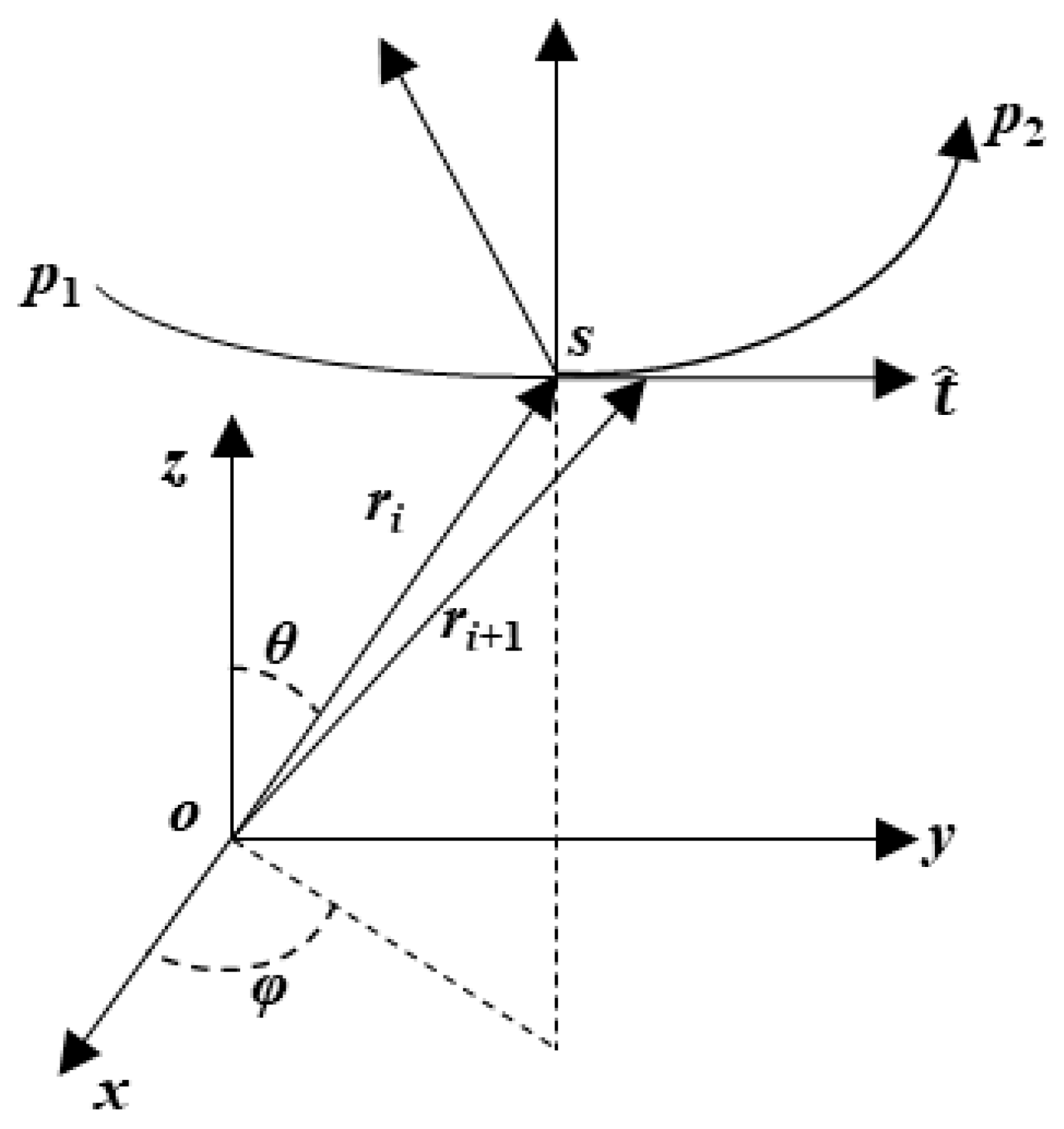
During the tracking process, the position vector and wave vector of points on the ray change along the integration path. Given the initial position, r, θ, φ, and initial wave vector, kr0, kθ0, kφ0, the position vector and wave vector after one step can be obtained by solving the equation set using the Runge–Kutta method. The entire ray tracing process continues by iteratively solving the Haselgrove equation set until the ray intersects the observation plane. As shown in Figure 2, p1 and p2 are the initial and final points of the ray, respectively, and ri is the position at the with i step of the ray tracing. The electric field of electromagnetic rays in spherical coordinates satisfies the following equation:
E s + 1 2 1 n 2 ϕ ln μ s E + E ln n t ^ = 0 ,
where E is the electric field; φ is the potential function; μ is the magnetic permeability; s is the arc length along the curved trajectory; n is the refractive index; t ^ is the tangent direction of the ray. From Equation (3), the direction of the electric field e ^ and its tangential derivative along the ray trajectory can be derived. The polarization direction of the electric field at that point is determined by the tangential direction at a point on the ray and the gradient of the refractive index.
e ^ = E E E * 1 / 2
e ^ s = e ^ Δ ln n t ^
As shown in Figure 3, P1(r0) is the initial point of the ray, ri is the position at the i step of the ray tracing, and P2(rm) is the final point of the ray, where m is the total number of steps in the ray tracing when the ray reaches the observation plane. After determining the ray path, the phase change in the ray can be calculated using segment-by-segment path integration as shown in the following equation:
I = k 0 P 1 p 2 nds ,
where n(i) is the refractive index of Δsi = ri+1ri. Given the initial incident polarization vector, the polarization vector at the intersection point of the ray with the observation surface can be obtained using Equations (4) and (5), denoted as the output polarization vector, e ^ o u t . Given the refractive index, ni, at the initial point of the ray, the refractive index, nf, at the endpoint, and the divergence factor, DF, of the ray tube, the electric field strength, Eout, at the observation surface can be calculated using the following equation:
E o u t = E 0 exp i k 0 I D F n i / n f 1 / 2 e ^ o u t

2.2. GPU Parallel Implementation of RT Method

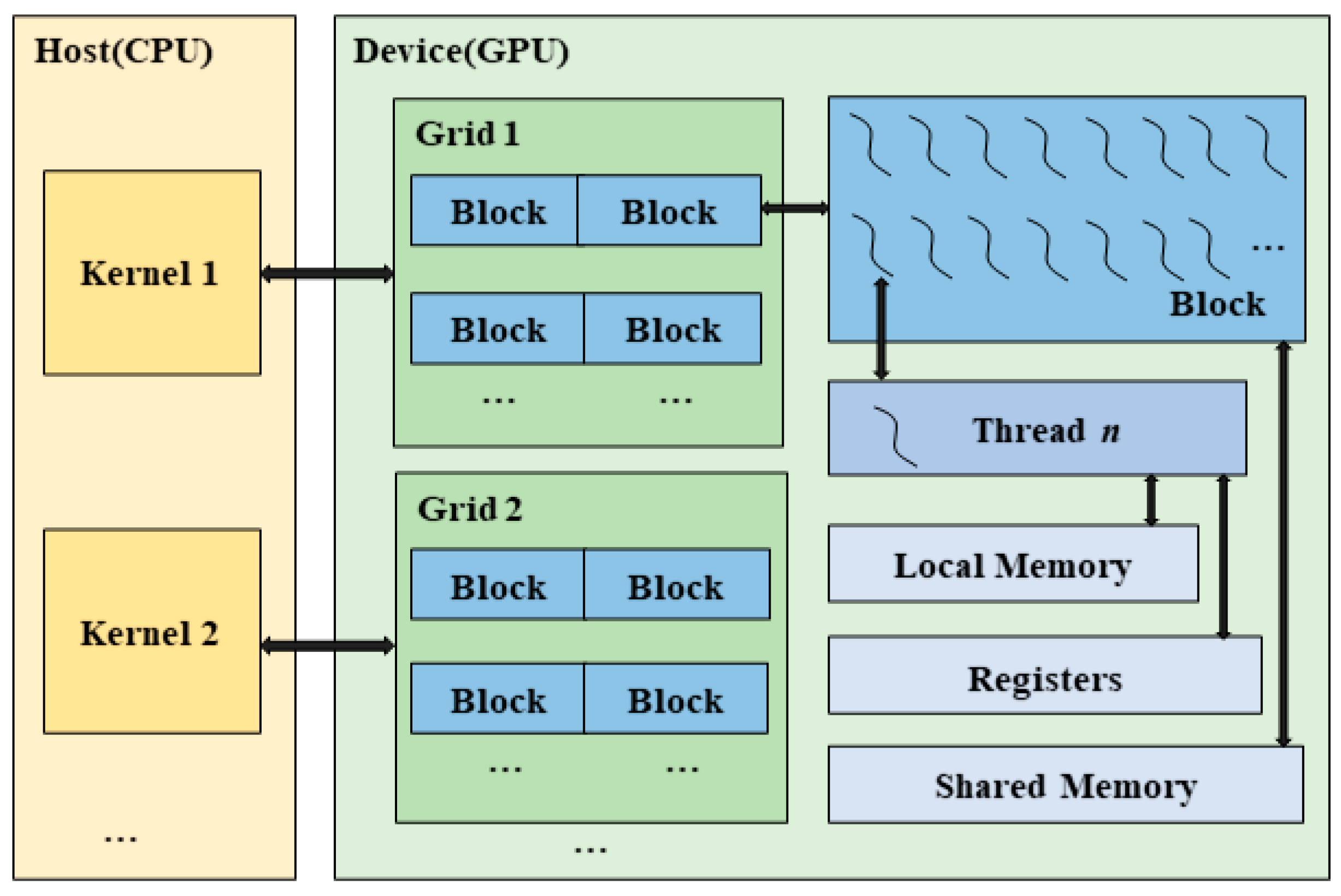
The compute unified device architecture (CUDA) is a general-purpose parallel computing architecture developed by NVIDIA. It is utilized in this paper to leverage its built-in stream multiprocessors to execute multiple threads in parallel, thereby solving computational problems related to inhomogeneous plasmas more efficiently than the CPU. In Figure 4, CUDA employs a heterogeneous programming model, designating the CPU as the host and the GPU as the device. The GPU acts as a coprocessor driven by the CPU, allowing for asynchronous parallel execution of kernel functions on the GPU. During the heterogeneous implementation process, the parallel kernel function set on the host corresponds with the grid on the device. The grid consists of several blocks, each containing multiple threads. These threads are organized into a warp, namely the minimum dispatching unit for the GPU thread, and each warp has 32 threads. Each warp within the same warp executes the same instruction in a single instruction multiple, data manner on the same streaming multiprocessor. Threads can access data from multiple memory spaces throughout execution, and each thread has its private local memory and registers while also having access to shared global memory.
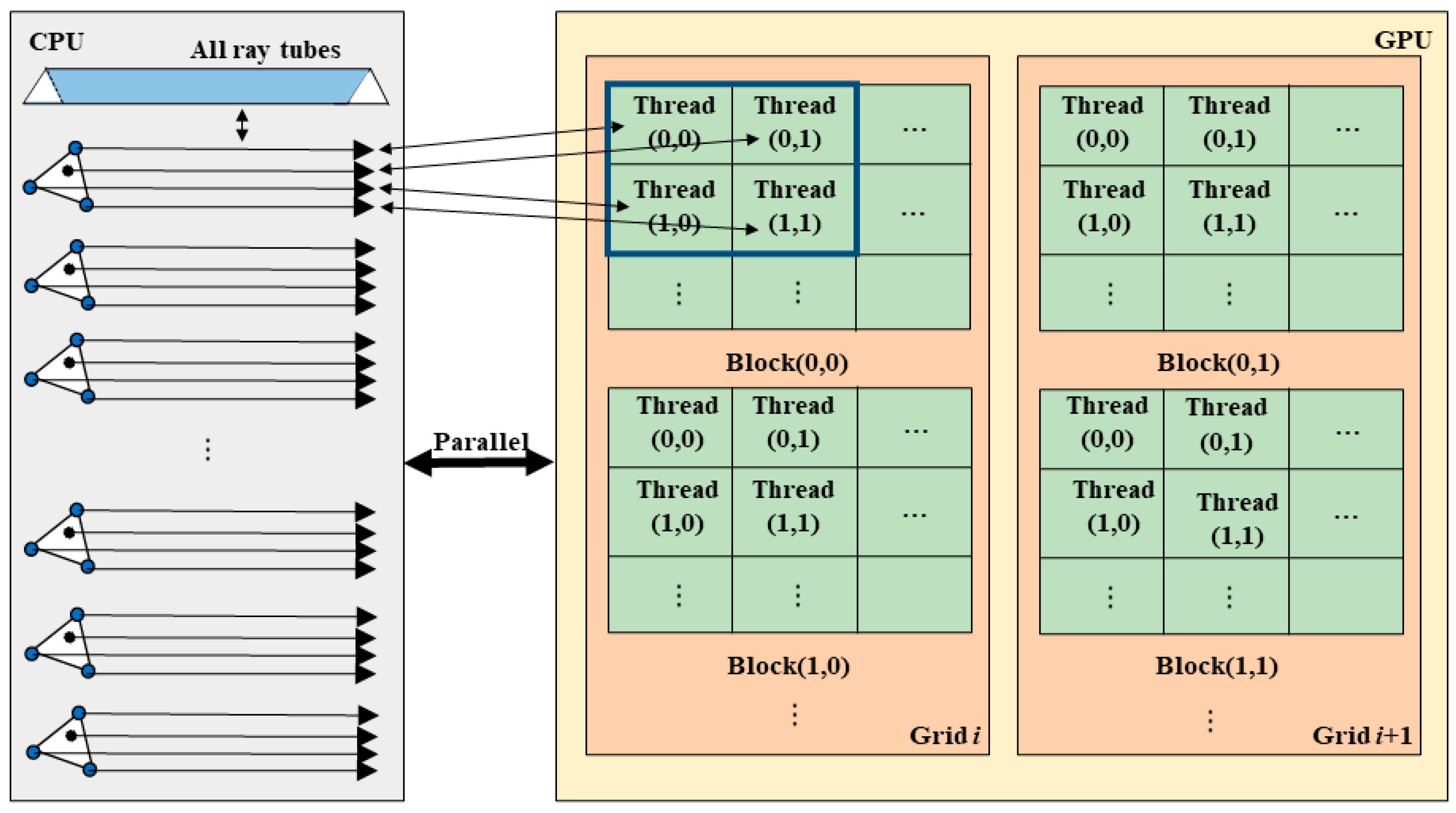
In the RT algorithms, the tracking and scattering field computation of each ray is an independent process that does not require access to other rays, thereby exhibiting high parallelism. This characteristic makes it highly suitable for GPU parallel computing, where a separate thread is used to compute each ray. Therefore, we focus on parallelizing the ray tracking within each ray tube on the GPU, namely parallelizing the process of solving the Haselgrove equations using the fourth-order Runge–Kutta method when an EM wave is incident on an inhomogeneous plasma. Once the incident wave and plasma target medium are determined, the initial ray tubes are established, and the incident wave is divided into a ray grid at each incident direction. Figure 5 illustrates the parallelization principle of the RT method, where the number of ray tubes becomes extremely large as the discretization becomes finer. Each ray tube consists of a central ray and three vertex rays after triangular mesh discretization. Each central ray and vertex ray within a ray tube is assigned to a group of threads within a block, with each group consisting of four threads corresponding to the three vertex rays and one central ray. Consequently, when the incident wave is divided into n ray tubes, we need to allocate n threads for central ray calculations and an additional 3*n threads for vertex ray calculations.
The core of this parallel algorithm program consists of two kernel functions responsible for tracking the vertex rays and central rays within ray tubes. The kernel functions for vertex rays and central rays are each associated with a grid for computation. After compiling the kernel functions with the device instruction set, the generated program is transmitted to the device. When invoking the parallel kernel functions for vertex rays and central rays, each thread computes one central ray or vertex ray and is located using threadID and blockID. Different vertex threads and midpoint threads are independent of each other. Therefore, the threads of vertex rays and midpoint rays perform parallel ray tracing calculations program simultaneously. A large number of threads execute the same tracking computation code in parallel on the device, iteratively solving the Haselgrove equations to track the ray trajectory at each step until the ray intersects the observation plane. Additionally, each block is executed in parallel on a single GPU multiprocessor, with no fixed execution order between blocks. Throughout the whole computation, the GPU calls the required number of threads to perform tracking calculations simultaneously, ultimately obtaining the entire path data for each ray and the final point information on the reference plane. The number of blocks is determined by the number of rays. For instance, when generating 1452 rays, to maximize the number of blocks in an SM while ensuring threads are a multiple of 32 and an SM can have up to 1.5k threads, testing shows that allocating 512 threads per block achieves the highest hardware utilization.
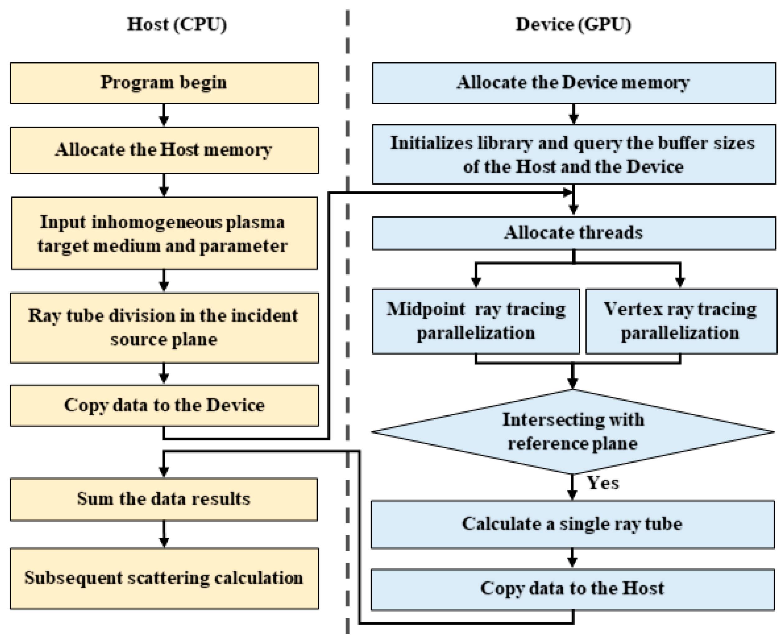
Figure 6 shows the specific workflow of the GPU-based parallel RT algorithm. The GPU parallel algorithm for RT is primarily divided into the host and the device. The host executes the serial computation portion while the device executes the parallel computation portion. According to the CUDA programming model, before launching the kernel functions for the vertex rays and midpoint rays, we allocate memory on both the device and host, select grid and block sizes, and determine the data that need to be transferred between the host and device. Next, the initial data stream for ray path tracking is transmitted from the host to the device. Since the most time-consuming aspect of the RT algorithm is the ray path tracking, parallel computations for path tracking of all rays are performed on the device. After calculating and tracing the ray, we determine whether each ray intersects with the reference plane and return the coordinates of any intersections on the device. Additionally, it is necessary to calculate the wave vector components at the emission point, the phase change variables during the ray propagation process, and the electric field components on the reference plane. Then, these are used to compute the phase change in the ray through segment-by-segment path integration, and the polarization of the electromagnetic wave is calculated based on the gradient of the refractive index and the direction of propagation. Finally, a total calculation for integrating a single ray tube is performed, and the resulting data are transmitted back from the device to the host for subsequent scattering calculations.

3. Results and Discussion

To demonstrate the effectiveness and performance of the EM scattering simulations computation, we employed both the serial RT method and the GPU-based parallel RT algorithm to calculate the scattering characteristics in an inhomogeneous plasma target within the same simulation environment with an EM wave incident. The implementation is performed on an NVIDIA RTX 4060 and RTX 4090 GPU card and an Intel i5-9400 CPU. The inhomogeneous plasma sphere with radius a is positioned at the origin of the coordinate system. Within the range of r < a/4, the refractive index is n = 2, while in the range of a/4 < r < a, the refractive index decreases linearly from n = 2 to n = 1. A circular aperture antenna with a radius of 30 cm is introduced as the emission source and placed on the left side of the medium, and the frequency of the incident wave f is 0.05 GHz.
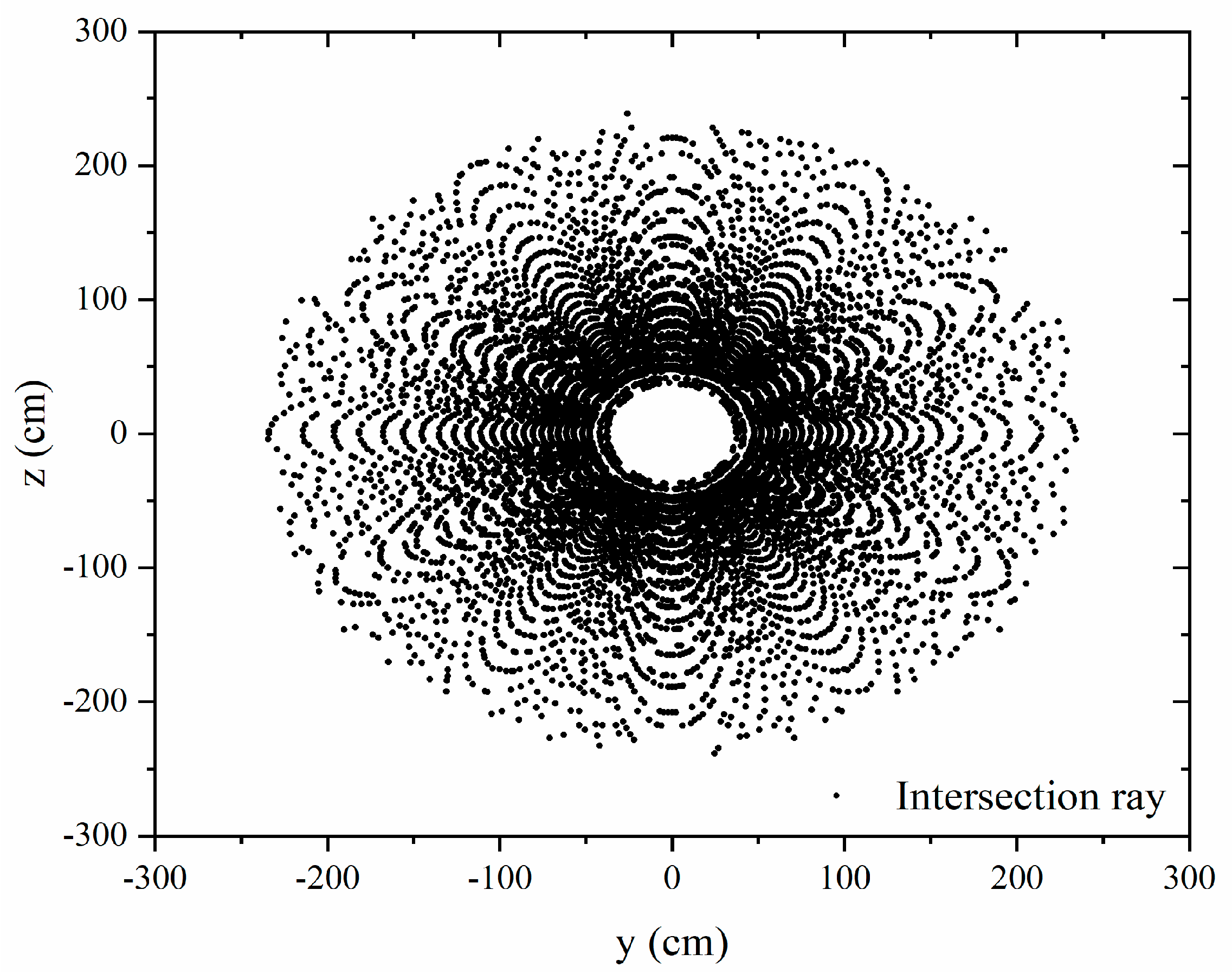
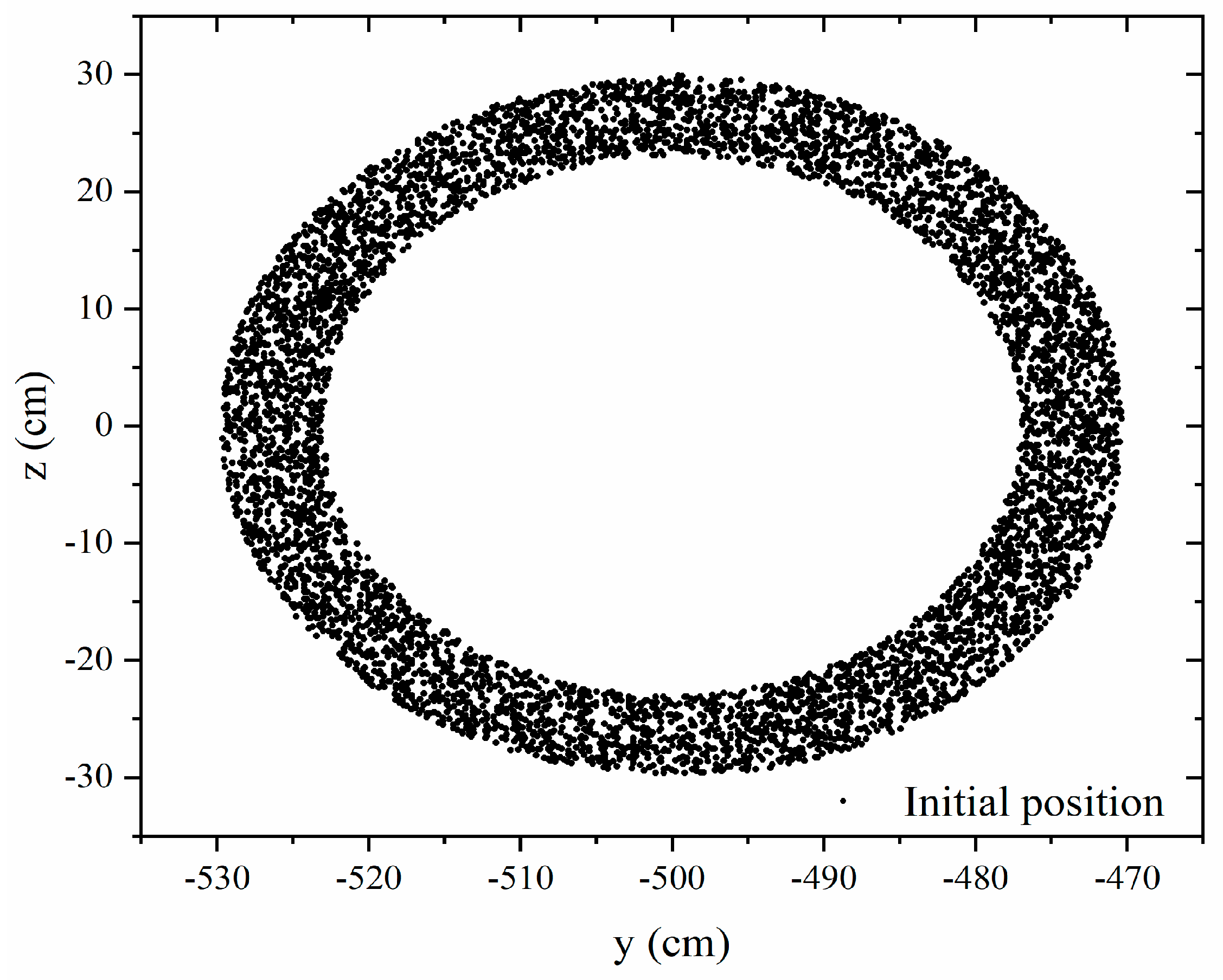
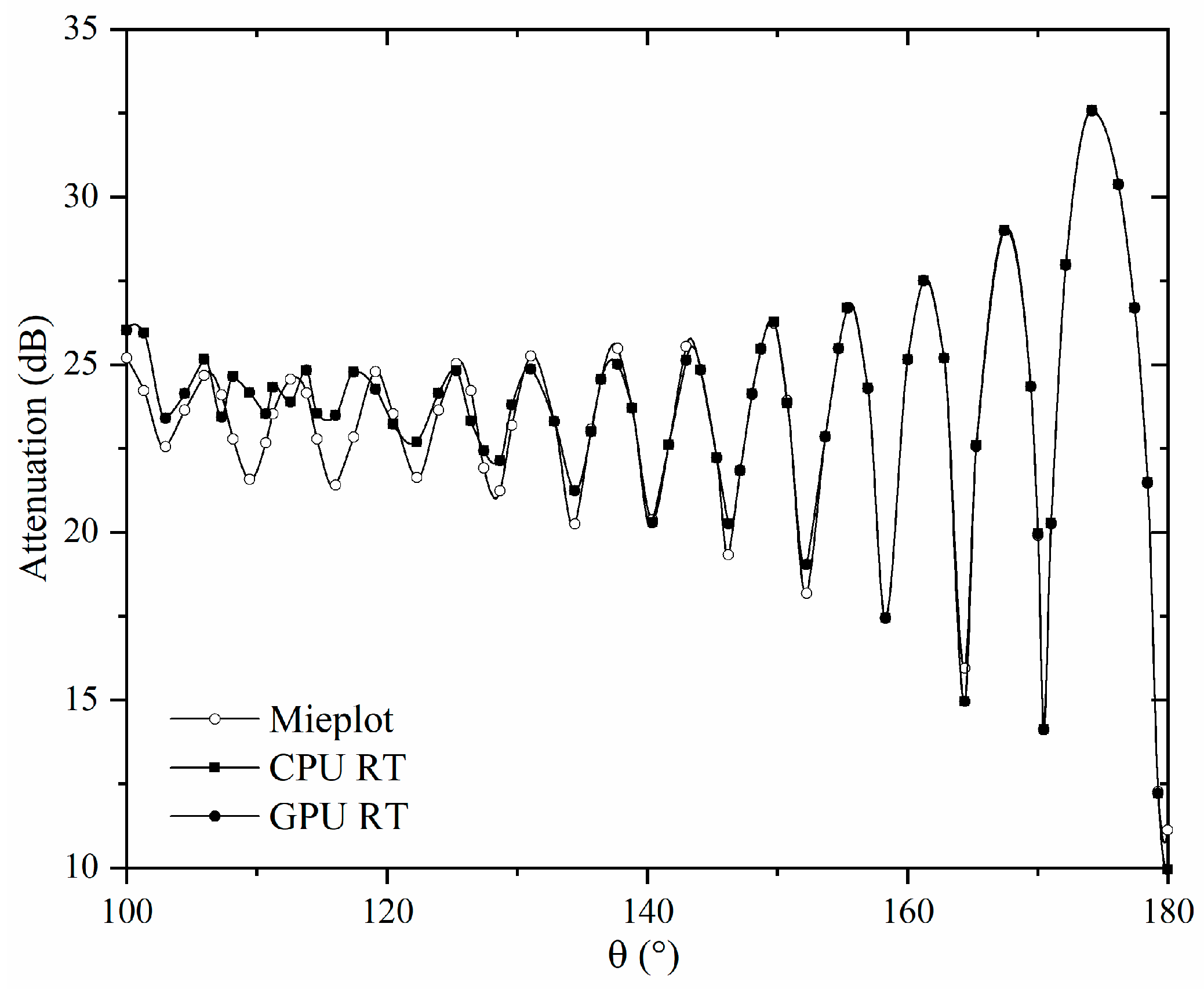
The final intersection points of rays with the observation plane are computed and their distribution is shown in Figure 7. The backscattering of the plasma sphere is obtained at a/λ = 5. As shown in Figure 8, these intersecting rays contribute to backscattering and their initial location is in a ring region from r = 22 to r = 30 on the emission surface of the antenna in the yoz plane. This is because rays starting near the center of the antenna aperture can pass through the target and contribute to forward scattering, while those starting near the edge can reach the observation plane and contribute to backscattering. Figure 9 presents the backscattering calculation results for an inhomogeneous plasma sphere using both serial and GPU-based parallel RT algorithms. It shows the attenuation of backscattering on the observation plane relative to the plasma target’s incident source. By calculating the mean square error (MSE) of the numerical results between different algorithms, the MSE between the CPU serial and the commercial software Mieplot is 0.55425. The numerical results of our RT algorithm and Mieplot are consistent, thereby validating the accuracy of our RT algorithm. Meanwhile, the numerical results of the GPU parallel are essentially consistent with the CPU serial, confirming the accuracy of the GPU-based parallel RT algorithm. Therefore, the GPU-based parallel RT algorithm demonstrates both accuracy and feasibility for EM scattering calculations in inhomogeneous plasma.
Table 1 shows the algorithm execution time of the GPU parallel and the CPU serial. Pn is the number of data points. Tn is the number of triangular faces, namely the number of midpoint rays. To assess the efficiency of the GPU parallel RT method under different performance conditions, we compared the simulation computation time of different series of graphics cards while varying the initial number of rays generated. As shown in Table 1, when the number of ray tubes increases, the execution time of the GPU-based parallel is significantly reduced in different hardware environments while using an RTX 4090 graphics card and an RTX 4060 graphics card. The GPU possesses numerous computational cores that provide superior acceleration performance compared to the CPU, as they reduce the time taken for each computational task and enhance overall throughput. Although there are communication issues between the CPU and GPU in parallel RT algorithm, the communication times can be negligible when dealing with large-scale data. Therefore, the GPU parallel RT algorithm effectively increases the computational speed by assigning the vertex rays and center rays within each ray tube to individual threads for parallel tracking computations.
The acceleration ratios of the GPU parallel RT algorithm compared to its serial counterpart across different hardware capabilities are shown in Table 2. The data indicate that the parallel RT scheme consistently achieves high acceleration ratios relative to its serial version. When the number of central rays is 565,796, the maximum speed-up of the RTX 4060 graphics card reaches 52.6×, and that of the RTX 4090 graphics card reaches 327.3×. As the number of generated ray tubes increases, the speed-up of the GPU parallel RT algorithm becomes increasingly efficient. It is attributed to the growing amount of parallel data as the number of ray tubes increases, which enhances the parallelism and efficiency. Additionally, the acceleration effect of the RTX 4090 reached approximately 6.2 times that of the RTX 4060 when the number of center rays was 565,796. The RTX 4090 superior hardware capabilities have more computational cores for parallel processing and larger memory capacity for handling larger-scale simulations. The above results indicate that the GPU-based parallel RT algorithm significantly improves computational efficiency while maintaining accuracy compared to its serial counterpart. Overall, the GPU-based parallel RT algorithm is highly suitable for high-performance EM research and can substantially optimize computational efficiency in EM scattering calculations involving inhomogeneous plasma, effectively expanding the real-time application range of RT algorithms.

4. Conclusions

This paper presents a GPU-based parallel algorithm RT algorithm applied to the efficient computation of scattering characteristics when a plane wave interacts with an inhomogeneous plasma target. It involves thread allocation for the vertex rays and midpoint rays of the triangular ray tubes in the RT method, with each thread independently handling the path tracking for a single ray. This algorithm effectively parallelizes the ray path tracking process of solving the Haselgrove equations using the fourth-order Runge–Kutta method in the serial RT algorithm. It reduces execution time and enhances computational efficiency by parallelizing the tracking of multiple rays. In identical simulation conditions, the numerical results of the parallel RT algorithm are consistent with the serial RT algorithm. The results indicate that the maximum speed-up of the GPU parallel RT algorithm achieves approximately 330× while maintaining accuracy. This parallel RT algorithm is suitable for efficient computation of EM wave propagation and scattering in symmetrical inhomogeneous plasma on a single graphics card, thereby providing a basic solution for the next step of multi-GPU efficient parallel of large-scale complex plasmas calculation.

Author Contributions

Conceptualization, Y.W.; Data curation, Y.W.; Formal analysis, X.H.; Funding acquisition, X.H. and B.W.; Investigation, B.W.; Methodology, Y.W. and B.W.; Software, Y.W. and X.H.; Supervision, B.W.; Validation, Y.W. and X.H.; Writing—original draft, Y.W.; Writing—review and editing, Y.W. and X.H. All authors have read and agreed to the published version of the manuscript.

Funding

This work was supported in part by the National Natural Science Foundation of China (Grant 62201411, 62371378, and 62471352); in part by the Fundamental Research Funds for the Central Universities (XJSJ24035).

Data Availability Statement

The original contributions presented in the study are included in the article, further inquiries can be directed to the corresponding author.

Conflicts of Interest

The authors declare no conflicts of interest.

Abbreviations

The following abbreviations are used in this manuscript:
RTRay Tracing
GPUGraphic Processing unit
CUDACompute Unified Device Architecture
EMElectromagnetic

References

  1. Wang, Z.; Guo, L.; Li, J. Analysis of Echo Characteristics of Spatially Inhomogeneous and Time-Varying Plasma Sheath. IEEE Trans. Plasma Sci. 2021, 49, 1804–1811. [Google Scholar] [CrossRef]
  2. Cheng, G.; Liu, L. Direct Finite-Difference Analysis of the Electromagnetic-Wave Propagation in Inhomogeneous Plasma. IEEE Trans. Plasma Sci. 2010, 38, 3109–3115. [Google Scholar] [CrossRef]
  3. Khojeh, G.; Abdoli-Arani, A. Scattering and resonant frequency of a toroidal plasma covered by a dielectric layer. Chin. J. Phys. 2022, 77, 945–955. [Google Scholar] [CrossRef]
  4. Chen, K.; Xu, D.; Li, J.; Zhong, K.; Yao, J. Studies on the propagation properties of THz wave in inhomogeneous dusty plasma sheath considering scattering process. Results Phys. 2021, 24, 104109. [Google Scholar] [CrossRef]
  5. Yang, X. Modeling and Simulation of Wideband Radio Waves Traveling Through Plasma Coupling with Uniform Magnetic Fields. IEEE Trans. Plasma Sci. 2022, 50, 3824–3829. [Google Scholar] [CrossRef]
  6. Song, L.; Li, X.; Liu, Y. Effect of Time-Varying Plasma Sheath on Hypersonic Vehicle-Borne Radar Target Detection. IEEE Sens. J. 2021, 21, 16880–16893. [Google Scholar] [CrossRef]
  7. Ouyang, W.; Ding, C.; Liu, Q.; Lu, Q.; Wu, Z. Influence analysis of uncertainty of chemical reaction rate under different reentry heights on the plasma sheath and terahertz transmission characteristics. Results Phys. 2023, 53, 106983. [Google Scholar] [CrossRef]
  8. Cong, Z.; Chen, R.; He, Z. Numerical modeling of EM scattering from plasma sheath: A review. Eng. Anal. Bound. Elem. 2022, 135, 73–92. [Google Scholar] [CrossRef]
  9. Zhang, Y.; Xu, G.; Zheng, Z. Propagation of terahertz waves in a magnetized, collisional, and inhomogeneous plasma with the scattering matrix method. Optik 2019, 182, 618–624. [Google Scholar] [CrossRef]
  10. Ding, Y.; Bai, B.; Gao, H.; Niu, G.; Shen, F.; Liu, Y.; Li, X. An Analysis of Radar Detection on a Plasma Sheath Covered Reentry Target. IEEE Trans. Aerosp. Electron. Syst. 2021, 57, 4255–4268. [Google Scholar] [CrossRef]
  11. Chung, S. FDTD simulations on radar cross sections of metal cone and plasma covered metal cone. Vacuum 2012, 86, 970–984. [Google Scholar] [CrossRef]
  12. Zhang, D.; Liao, W.; Sun, X.; Chen, W.; Yang, L. Study on the Electromagnetic Scattering Characteristics of Time-Varying Dusty Plasma Target in the BGK Collision Model-TM Case. IEEE Trans. Plasma Sci. 2025, 53, 116–121. [Google Scholar] [CrossRef]
  13. Singh, A.; Walia, K. Self-focusing of Gaussian laser beam in collisionless plasma and its effect on stimulated Brillouin scattering process. Opt. Commun. 2013, 290, 175–182. [Google Scholar] [CrossRef]
  14. Xiang, H.; Chen, J.; Ni, X.; Chen, Y.; Zeng, X.; Gu, T. Numerical Investigation on Interference and Absorption of Electromagnetic Waves in the Plasma-Covered Cavity Using FDTD Method. IEEE Trans. Plasma Sci. 2012, 40, 1010–1018. [Google Scholar] [CrossRef]
  15. Wei, B.; Li, L.; Yang, Q.; Ge, D. Analysis of the transmission characteristics of radio waves in inhomogeneous weakly ionized dusty plasma sheath based on high order SO-DGTD. Results Phys. 2017, 7, 2582–2587. [Google Scholar] [CrossRef]
  16. Chen, W.; Guo, L.; Li, J.; Liu, S. Research on the FDTD Method of Electromagnetic Wave Scattering Characteristics in Time-Varying and Spatially Nonuniform Plasma Sheath. IEEE Trans. Plasma Sci. 2016, 44, 3235–3242. [Google Scholar] [CrossRef]
  17. Zhang, M.; Liao, C.; Xiong, X.; Ye, Z.; Li, Y. Solution and design technique for beam waveguide antenna system by using a parallel hybrid-dimensional FDTD method. IEEE Antennas Wirel. Propag. Lett. 2016, 16, 364–368. [Google Scholar] [CrossRef]
  18. Warren, C.; Giannopoulos, A.; Gray, A.; Giannakis, I.; Patterson, A.; Wetter, L.; Hamrah, A. A CUDA-based GPU engine for gprMax: Open source FDTD electromagnetic simulation software. Comput. Phys. Commun. 2019, 237, 208–218. [Google Scholar] [CrossRef]
  19. Kim, K.H.; Park, Q.H. Overlapping computation and communication of three-dimensional FDTD on a GPU cluster. Comput. Phys. Commun. 2012, 183, 2364–2369. [Google Scholar] [CrossRef]
  20. Gunawardana, M.; Kordi, B. GPU and CPU-based parallel FDTD methods for frequency-dependent transmission line models. IEEE Lett. Electromag. 2022, 4, 66–70. [Google Scholar] [CrossRef]
  21. Liu, S.; Zou, B.; Zhang, L.; Ren, S. A multi-GPU accelerated parallel domain decomposition one-step leapfrog ADI-FDTD. IEEE Antennas Wirel. Propag. Lett. 2020, 19, 816–820. [Google Scholar] [CrossRef]
  22. Stefanski, T.; Drysdale, T.D. Parallel ADI-BOR-FDTD algorithm. IEEE Microw. Wirel. Compon. Lett. 2008, 18, 722–724. [Google Scholar] [CrossRef]
  23. Francés, J.; Otero, B.; Bleda, S.; Gallego, S.; Beléndez, A. Multi-GPU and multi-CPU accelerated FDTD scheme for vibroacoustic applications. Comput. Phys. Commun. 2015, 191, 43–51. [Google Scholar] [CrossRef]
  24. Zhou, Q.; Xu, W.; Feng, Z. A Coupled FEM-MPM GPU-based algorithm and applications in geomechanics. Comput. Geotech. 2022, 151, 104982. [Google Scholar] [CrossRef]
  25. Sellami, H.; Cazenille, L.; Fujii, T.; Hagiya, M.; Aubert-Kato, N.; Genot, A.J. Accelerating the Finite-Element Method for Reaction-Diffusion Simulations on GPUs with CUDA. Micromachines 2020, 11, 881. [Google Scholar] [CrossRef]
  26. Chen, Z.; Zhang, Q.; Fu, S.; Wang, X.; Qiu, X.; Wu, H. Hybrid Full-Wave Analysis of Surface Acoustic Wave Devices for Accuracy and Fast Performance Prediction. Micromachines 2021, 12, 5. [Google Scholar] [CrossRef]
  27. Kee, C.Y.; Wang, C.F. Efficient GPU Implementation of the High-Frequency SBR-PO Method. IEEE Antennas Wirel. Propag. Lett. 2013, 12, 941–944. [Google Scholar] [CrossRef]
  28. Gökkaya, E.; Saynak, U. An Approach for RCS Estimation Based on SBR Implemented on GPU. In Proceedings of the 2024 32nd Signal Processing and Communications Applications Conference (SIU), Mersin, Turkiye, 15–18 May 2024; pp. 1–4. [Google Scholar] [CrossRef]
  29. Wu, X.; Su, L.; Wang, K.; Li, Y. GPU-accelerated Calculation of Acoustic Echo Characteristics of Underwater Targets. In Proceedings of the 2020 Asia-Pacific Conference on Image Processing, Electronics and Computers (IPEC), Dalian, China, 14–16 April 2020; pp. 227–231. [Google Scholar] [CrossRef]
  30. Huo, J.; Xu, L.; Shi, X.; Yang, Z. An Accelerated Shooting and Bouncing Ray Method Based on GPU and Virtual Ray Tube for Fast RCS Prediction. IEEE Antennas Wirel. Propag. Lett. 2021, 20, 1839–1843. [Google Scholar] [CrossRef]
  31. Zhou, J.; Wen, D. Research on Ray Tracing Algorithm and Acceleration Techniques using KD-tree. In Proceedings of the 2021 6th International Conference on Intelligent Computing and Signal Processing (ICSP), Xi’an, China, 9–11 April 2021; pp. 107–110. [Google Scholar] [CrossRef]
  32. Yang, M.; Jia, J. Implementation and Optimization of Hardware-Universal Ray-tracing Underlying Algorithm Based on GPU Programming. In Proceedings of the 2023 6th International Conference on Artificial Intelligence and Big Data (ICAIBD), Chengdu, China, 26–29 May 2023; pp. 171–178. [Google Scholar] [CrossRef]
  33. Chen, J.; Wang, Y.; Huang, J.; Wang, C.X. A Novel GPU Acceleration Algorithm Based on CUDA and MPI for Ray Tracing Wireless Channel Modeling. In Proceedings of the 2023 IEEE Wireless Communications and Networking Conference (WCNC), Glasgow, UK, 26–29 March 2023; pp. 1–6. [Google Scholar] [CrossRef]
  34. Breglia, A.; Capozzoli, A.; Curcio, C.; Liseno, A. Ultrafast ray tracing for electromagnetics via kD-tree and BVH on GPU. In Proceedings of the 2015 31st International Review of Progress in Applied Computational Electromagnetics (ACES), Williamsburg, VA, USA, 22–26 March 2015; pp. 1–2. [Google Scholar]
  35. Meng, X.; Guo, L.; Fan, T. Parallelized TSM-RT Method for the Fast RCS Prediction of the 3-D Large-Scale Sea Surface by CUDA. IEEE J. Sel. Top. Appl. Earth. 2015, 8, 4795–4804. [Google Scholar] [CrossRef]
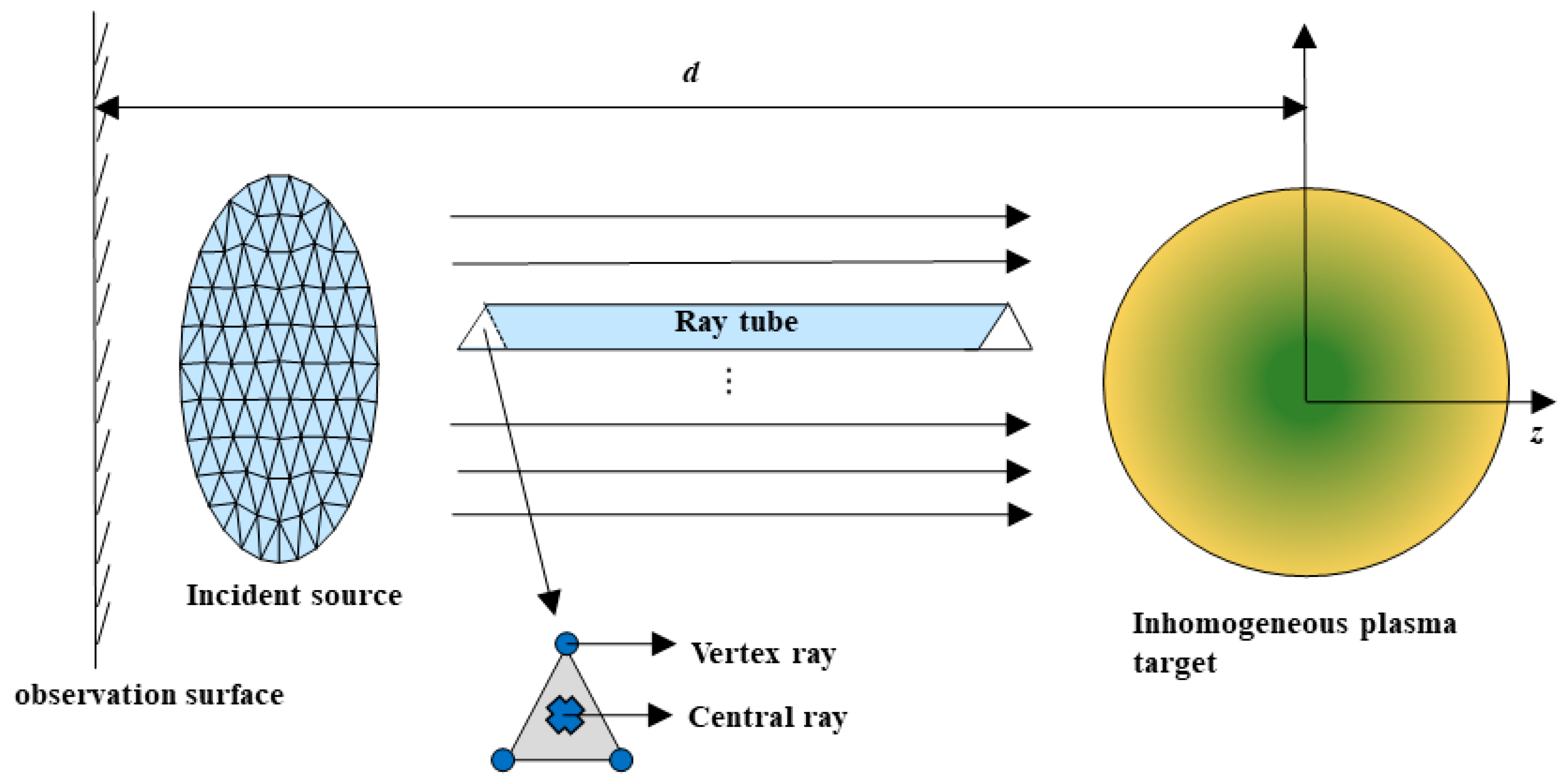
Figure 1. The division principle of ray tube in the ray tracing process.
Symmetry 17 00627 g001
Figure 2. Ray trajectories and local coordinates in spherical coordinates.
Symmetry 17 00627 g002
Figure 3. Calculation of ray phase.
Symmetry 17 00627 g003
Figure 4. Thread structure in CUDA.
Symmetry 17 00627 g004
Figure 5. Thread allocation for parallel RT algorithm.
Symmetry 17 00627 g005
Figure 6. Flowchart of the GPU-based parallel RT algorithm.
Symmetry 17 00627 g006
Figure 7. The distribution of ray intersections in the backscattered part on the observation plane.
Symmetry 17 00627 g007
Figure 8. The position region of the ray incident wave that contributes to backscattering.
Symmetry 17 00627 g008
Figure 9. The backscattering simulation of the inhomogeneous plasma target using the serial RT algorithm and parallel RT algorithm.
Symmetry 17 00627 g009
Table 1. Comparison of execution time by the CPU serial and GPU parallel.
(Pn, Tn)CPU SerialGPU Parallel
(RTX 4060)
GPU Parallel
(RTX 4090)
(1452, 2774)90.5 s8.8 s5.6 s
(2267, 4347)140.0 s12.97.9 s
(9062,17,813)577.5 s25.98.7 s
(36,268, 71,898)2358.9 s40.3 s10.0 s
(284,151, 565,796)15875.4 s271.1 s48.5 s
Table 2. Speed-up and Comparison of the GPU parallel by RTX 4060 and RTX 4090.
NVIDIA
GeForce RTX
Graphics Card
(1452, 2774)(2267, 4347)(9062, 17,813)(36,268, 71,898)(284,151, 565,796)
RTX 406010.3×10.8×22.3×58.5×52.6×
RTX 409016.2×17.7×66.4×235.9×327.3×
Disclaimer/Publisher’s Note: The statements, opinions and data contained in all publications are solely those of the individual author(s) and contributor(s) and not of MDPI and/or the editor(s). MDPI and/or the editor(s) disclaim responsibility for any injury to people or property resulting from any ideas, methods, instructions or products referred to in the content.