Article

On the Adsorption Mechanism of Humic Substances on Kaolinite and Their Microscopic Structure

by
Edgar Galicia-Andrés
1,2,*,
Chris Oostenbrink
1,
Martin H. Gerzabek
2 and
Daniel Tunega
2,3,*
1
Institute of Molecular Modeling and Simulation, University of Natural Resources and Life Sciences, 1190 Vienna, Austria
2
Institute of Soil Research, University of Natural Resources and Life Sciences, 1190 Vienna, Austria
3
School of Pharmaceutical Science and Technology, Tianjin University, Tianjin 300350, China
*
Authors to whom correspondence should be addressed.
Minerals 2021, 11(10), 1138; https://doi.org/10.3390/min11101138
Submission received: 15 September 2021 / Revised: 11 October 2021 / Accepted: 14 October 2021 / Published: 17 October 2021
(This article belongs to the Special Issue Recent Advances in Molecular Modeling of Clay Minerals Interfaces)

Abstract

:
Soil organic matter (SOM) and various inorganic minerals represent key components of soils. During pedogenesis and due to biological activity these species interact, having a crucial impact on the formation of an aggregated soil structure with a hierarchical arrangement from nano to macro scale. In this process, the formation of organo–mineral microaggregates represents a dominant factor affecting soil functions and properties. This study focuses on the interactions between humic substances (HSs) and the mineral kaolinite as typical representatives of SOM and soil minerals. By performing classical molecular dynamics (MD) simulations on models of HSs and kaolinite, we demonstrate how two dominant but chemically different kaolinite surfaces affect the stability of HSs microaggregates. By analyzing volumetric, structural, and energetic properties of SOM–kaolinite models, we explain possible mechanisms of the formation of stable SOM–clay aggregates and show how a polarized environment affects the electrostatic interactions, stabilizing the microscopic structure of SOM–mineral aggregates. Our results showed that when stable aggregates of HSs are confined in kaolinite nanopores, their interactions with kaolinite surfaces disintegrate them into smaller subaggregates. These subaggregates are adsorbed more strongly on the polar aluminol surface of kaolinite compared to less the active hydrophobic siloxane surface.

1. Introduction

Soil represents a heterogeneous complex system formed from a mixture of different phases. The formation of different soil types during the pedogenesis is dictated by numerous factors such as the origin of parent materials, climate, vegetation, topographical relief, presence and activity of soil (micro)organisms, soil management, and time. Organic material in soils, generally called soil organic matter (SOM), is structurally and compositionally very complex matter originating from plant, animal, and microbial materials [1]. Owing to external conditions and aging, SOM is under permanent development and transformation, leading to the formation of persistent and stable organic phases. Detailed mechanisms by which SOM persists are not completely known. Several processes such as humification, selective preservation, and progressive decomposition were suggested to be responsible for SOM stabilization [2]. The recalcitrance and persistence of SOM arise as the result of the complex interplay of molecular properties, environmental, and microbial conditions [3].
One of the most typical features of the pedogenesis process is the formation of hierarchically organized aggregated structures at different scales (nano–to–macro) [4]. From the structural hierarchy, microaggregates are considered as one of the most important types responsible for the overall properties of SOM, the formation of networks of soil pores, and heterogeneous biogeochemical interfaces, the water retention capacity of soils, and the formation of larger-scale soil components, etc. [4,5,6,7,8]. A typical feature of soil microaggregates is their interactions with other soil components such as soil minerals. The formation of organo–mineral aggregates significantly enhances the SOM resistance and stability, preventing further SOM degradation and the accumulation of organic carbon [2,9,10,11]. The interactions of SOM with reactive mineral surfaces are very complex and include a wide range of interactions, from weak dispersion to electrostatic interactions between charged sites to strong chemical bonds. There is an intensive experimental effort to quantify and understand organic matter–mineral interface from classical experimental techniques (e.g., batch sorption experiments or calorimetry) to advanced techniques such as atomic force spectroscopy [12]. In the formation of SOM and/or SOM–mineral aggregates, an important role is attributed to soil solutions, particularly to water and its ability to from water hydrogen bond bridges, and/or inorganic cations naturally occurring in soil solutions (e.g., Na+, K+, Mg2+, or Ca2+) and their ability to form cation cross–linking bridges among sites of aggregate components [4,13,14,15,16,17,18,19,20]. Water and cations serve as a glue that, depending on water and cation content, can either enhance or weaken structural stability and resistance of the SOM itself and SOM–mineral aggregates.
In addition to intensive experimental efforts to understand the processes of aggregate formation, there are also simulation experiments (including molecular modeling) that contribute to a deeper understanding of the mechanisms of aggregate formation. Here, mainly modeling of organic matter represents a big challenge due to its structural complexity and heterogeneity. Apart from modeling minerals, where the structure and composition are unambiguously determined, SOM represents an undetermined problem from a compositional and structural point of view. Humic substances (HS) can be considered a major component of SOM. Thus, they can play a key role in important soil functions. Leonardite humic acid is often used as a model because it is characterized by a high content of HS, especially humic acids (HAs) [21].
The concept of SOM as supramolecular aggregates of low–weight molecular species (partly stabilized by hydrophobic interactions, hydrogen bonds, and metal cation bridges) was considered using structural models of diverse complexity [22,23,24,25,26,27]. A big qualitative step in molecular modeling was achieved by introducing the Vienna Soil–Organic–Matter Modeler (VSOMM) tool [28,29] that can generate highly concentrated, condensed–phase models of SOM with a wide range spectrum of molecular sizes, offering control over the chemical composition. Furthermore, the models can be used as a starting point to simulate the effect of environmental conditions such as water and cation content. This level of control over various physical parameters (e.g., an average molecule size of microaggregate components, protonation states, etc.) and chemical content (e.g., carbon content, nonpolar and polar functional groups, etc.) allows a deep study of processes of micro–aggregation. Very recently, we published a work in which the effect of cations and hydrogen bonds (H-bonds) on the SOM stabilization was explored by using supramolecular model aggregates resembling compositionally leonardite humic acid (LHA) [20]. By using classical molecular dynamics simulations and analyzing volumetric and structural properties, we elucidated the possible mechanisms and conditions (e.g., water content, cation type, and pH effect) on the formation of stable SOM aggregates.
Compared to modeling SOM aggregates, there have been far fewer attempts to model SOM mineral aggregates. For example, Ritschel and Totsche [30] developed a quantitative approach for the formation of soil microaggregates, integrating diffusion–limited cluster–cluster aggregation with a probabilistic attachment following the Derjaguin–Landau–Verwey–Overbeek (DLVO) theory of particle interactions. Their approach used typical shapes of microcrystals of typical soil minerals such as clays and iron oxides. In another work, interactions of natural organic matter (NOM) clusters in smectite mesopores were described by using classical molecular dynamics. The formation of these clusters was driven by hydrophobic interactions of aromatic/aliphatic regions within the clusters to minimize their interactions with water and charge–balancing cations [31]. On the other hand, Zhang et al. used a multiscale approach combining first–principles molecular dynamics and classical molecular dynamics to simulate clay finite particles interacting with SOMs [32]. By modeling different pH conditions and using models of different complexity, they found that under dry conditions, all reactive groups are relevant in the binding process; whereas under wet conditions, mainly chemical bonding of carboxylate, phosphate, and cation bridges are significant. Moreover, the interface formed between the soil solution and the mineral surface represents a typical example of an electrode in contact with an ionic solution [33]. Zhang [34] and Zhang et al. [35,36] showed that classical MD simulation of such interfaces exhibits a capacitor–like behavior. Depending on the boundary conditions and the nature of the solid surface, the distribution of molecular species in the solution leads to a different development of the electric double layer (EDL).
In this work, we focus on the modeling of SOM–clay interactions using models of kaolinite clay mineral that are typical for many and specifically highly weathered soils, as well as the model of the LHA aggregate developed in our previous work [37,38,39]. The LHA model used offers an opportunity to study systematically different types of interactions at the molecular level. We seek to reconcile new theories and hypotheses on SOM stability with previously well–established concepts. Various sectors of society can benefit from this work, from producers and farmers to the scientific community, as our results provide mechanistic insight into the processes of organic carbon fixation and even for the development of promising new materials. The main objectives of this work are: (i) to describe the adsorption mechanism of SOM aggregates on clay mineral reactive surfaces; (ii) to characterize the structure at the molecular scale of adsorbed species; (iii) to demonstrate that the polarized environment is the main driving force which promotes adsorption and to quantify this effect; and (iv) to assess the development of the EDL in terms of density profiles.

2. Materials and Methods

2.1. Initial Configuration

In this work, the leonardite humic acid model LHA1 developed by Petrov et al. [37,38] was used as a representative humic acid (HA) structure to build organo–mineral aggregates using the VSOMM online tool [28,29] (version 2.0, Institute of Molecular Modeling and Simulation – University of Natural Resources and Life Sciences, Vienna, Austria). The VSOMM tool generates condensed phase models of soil organic matter (SOM) based on the concept of building blocks. These building blocks represent small fragments of organic components typically found in soil organic matter. The modeler generates different combinations of building blocks from a database to match the elemental and organic fractions provided as input to generate a model of humic substances (HSs). Our LHA1 structure was comprised of 200 building blocks with five building blocks per molecule randomly linked. This model emulates circumneutral pH conditions, generating deprotonated carboxylate and carboxylic groups in a ratio [COO]/[COOH] = 631. The negative charge of carboxylate groups was neutralized by calcium cations (Ca2+) embedded in the aggregate model. These cations are essential for keeping the molecular rigidity of the HA models through cation bridges (CaB) [13,15,16,19,20,40,41].
For the modeling of organo–mineral aggregates, we used a pore space model with the mineral phase represented by a periodic kaolinite layer. The kaolinite layer consisted of 16 × 16 unit cells (8.3 × 14.3 nm2; in the a and b unit cell directions) from the bulk structure derived by Bish [42] parallel to the xy–plane, similar to that used in our previous works [40,41,43,44]. The kaolinite layer is formed from an octahedral AlOOH sheet and a tetrahedral SiO sheet; thus, two different basal surfaces exist—the aluminol basal surface [001] and the siloxane basal surface [00 1 ¯ ]. As the kaolinite layer was placed in a periodic box with z = 9.4 nm, the pore space of width of 8.7 nm was determined by these two surfaces. The HA aggregate was firstly equilibrated and placed in the middle of the pore space. The remaining empty space of the cavity was filled with water molecules with a density of 1 g cm−3.
Molecular interactions of HAs and metal cations were described according to the GROMOS force field parameters 54a7 [45]. The kaolinite was described by the ClayFF force field [46,47] and the water molecules by the simple point charge (SPC) model [48]. In previous works [40,41,43,44], the CLAYFF and the GROMOS54a7 have exhibited compatibility. This behavior is expected as both force fields are based on the SPC water model.

2.2. Simulation Settings

Molecular dynamics simulations were performed by the GROMACS package [49] (version 2018.8, Royal Institute of Technology and Uppsala University, Uppsala, Sweden) using the leap-frog algorithm to solve the equations of motion with a time step Δt = 2 fs. The temperature and pressure were kept constant at 300 K and 1 bar using the Berendsen thermostat and barostat with relaxation time constants τT = 0.1 ps and τP = 0.5 ps, respectively [50]. An atom–based cutoff radius, rcut, of 1.4 nm was used for all non–bonded interactions with energy and pressure corrections.
Long–range electrostatic interactions were treated using the smooth particle mesh Ewald (SPME) method [51]. The SPME used a grid spacing of 0.12 nm and a cubic polynomial. Lattice summation methods, better known as Ewald summation methods, provided efficient handling of long–ranged interactions under periodic boundary conditions in systems with a large number of particles (e.g., in biomolecular simulations) [52]. In these methods, electrostatic quantities are computed based on splitting the slowly convergent Coulombic potential into two (much faster) series, the so–called short– and long–range terms. The long–range term was performed in the reciprocal space, whereas the short–range term was in the real space. With this method, the electrostatic potential was calculated for the infinitely periodic system using the Fourier series [53].
The SETTLE algorithm was used to constrain bond lengths and angles of water molecules [54]; whereas the remaining bond lengths were constrained with the linear constraint solver (LINCS) algorithm [55].
The simulation protocol implemented was an energy minimization step following by an equilibration step before the production step. The maximum tolerance of the minimization step is 1000 kJ mol−1 nm−1. The equilibration step was performed at constant pressure for 120 ns and the production step for 100 ns due to the slow dynamics of the systems. All the molecular coordinates and energies were stored every 10 ps. All images were created by using the VMD software [56] (version 1.9.3, Beckman Institute for Advanced Science and Technology, National Institutes of Health, National Science Foundation, Physics, Computer Science, and Biophysics at University of Illinois at Urbana–Champaign, USA).

2.3. Radial Distribution Functions

To describe the microscopic structure, we used the radial distribution function (gij; RDF) between particles i and j [57], defined as
g i j ( r ) = V n i j ( r ) 4 π N j r 2 d r
g i j ( r , z ) = A n i j ( r , z ) 2 π N j r d r
Equation (1a) is the conventional RDF, where 〈nij(r)〉 is the average number of particles j around i at a distance between r and r + dr, Nj the number of j particles in the simulation box, and V the volume. Equation (1b) is the so–called lateral RDF (gij2D), where 〈nij(r,z)〉 is the average number of particles j around i at a distance between r and r + dr and in the lateral cut between z and z + dz, Nj of j particles in the lateral cut and A the area of the xy–plane. In Equation (1), the coordination shells could be obtained at each distinguishable minimum observed. The space up to the first minimum corresponded to the first coordination shell, the space from the first to the second minimum corresponded to the second coordination shell, and so on.
As in our previous work, we used the Ca2+–CCOO RDF to assess the inner–sphere /outer–sphere (ISC/OSC) complex distribution, Keq, of carboxylate groups by using the position of the first and second minima in the RDF, RL and RU, respectively [20].
K eq = R L R U g Ca 2 + C COO ( r ) r 2 d r 0 R U g Ca 2 + C COO ( r ) r 2 d r

3. Results

3.1. HA Adsorption

In Figure 1a,b, the non–bonded interaction energy time series of the equilibration stage evidences the adsorption process. At the beginning (t = 0 ns) the supramolecular aggregate is suspended in the middle of the pore (Figure 1c). After 10 ns, some LHA molecules and subclusters, and Ca2+ cations separated from the main aggregate (Figure 1d). During this process, disintegrated HAs were adsorbed on the aluminol side, whereas Ca2+ cations moved to the siloxane surface (Figure 1d). Ultimately, the different components of the original aggregate (HA and Ca2+) disperse on the respective sides (Figure 1e).
In the first 30 ns (region I in Figure 1a), a linear decrease in the HA–Kln and Ca2+–Kln energies corresponded to the disaggregation from the supramolecular structure and the adsorption of smaller HA aggregates on the kaolinite surfaces. In the next 45 ns (region II in Figure 1a), a change in the slope indicated another process. In this process, the adsorbed HA molecules accommodated on the surface. Finally, in the last 25 ns (region III in Figure 1a), a slope of zero indicated that an equilibrium was reached. On the other hand, although most cation bridges (CaBs) were destroyed to favor the adsorption of HAs on the kaolinite in the firsts 30 ns, the non–zero value of HA–Ca2+ energy (Figure 1b) revealed the presence of remaining CaBs in the HA aggregate residuals spread over the aluminol surface (Figure 1).

3.2. Molar Distribution Profiles

Once the equilibrium was reached, the amount of adsorbed molecules was quantified by the one–dimensional probability distribution profile, ρ. In Figure 2, the molecular distribution suggests the formation of a monolayer structure with oriented water molecules with a higher density in the vicinity of the aluminol and/or siloxane surfaces (Figure 2a,b, respectively). The profile exhibits the same trend throughout the whole pore, as in a previous work of pure water confined in a similar kaolinite pore subjected to constant electric fields [43].
Like water, Ca2+ cations accumulate on both sides of the surface but with a different distribution. On the siloxane side (Figure 2b), the intensity of the first maximum located at z = 0.46 nm exhibits Ca2+ high affinity to be adsorbed. The position of Ca2+’s peak relative to the water’s peak suggested that Ca2+ adorbed to the siloxane surface as hydrated cations, forming OSCs. On the aluminol side (Figure 2a), the distribution was much wider and more complex with three dominant peaks. The low intensity of the first maximum (Ca–z1) at z = 0.44 nm indicated that only a part of Ca2+ cations diffused close to the aluminol surface. These (partially) hydrated cations in the vicinity of the surface can form cation bridges between negatively charged sites in HA species (carboxylate groups) and surface OH groups. Figure 2a shows that HAs adsorbed preferentially only on the aluminol side, forming a monolayer as a broad peak (HA–z) with a maximum value at z = 0.56 nm and bounded by the minimum at z = 1.15 nm (Figure 1e). This broad HA peak overlapped with the first and second peaks of Ca2+, implying that HAs and Ca2+s interacted via CaBs. Moreover, the increased intensity of Ca2+‘s second maximum (Ca–z2) at z = 0.74 nm, compared to Ca–z1, suggests higher affinity of cations for HAs than for the aluminol surface.

3.3. Electrostatic Interactions

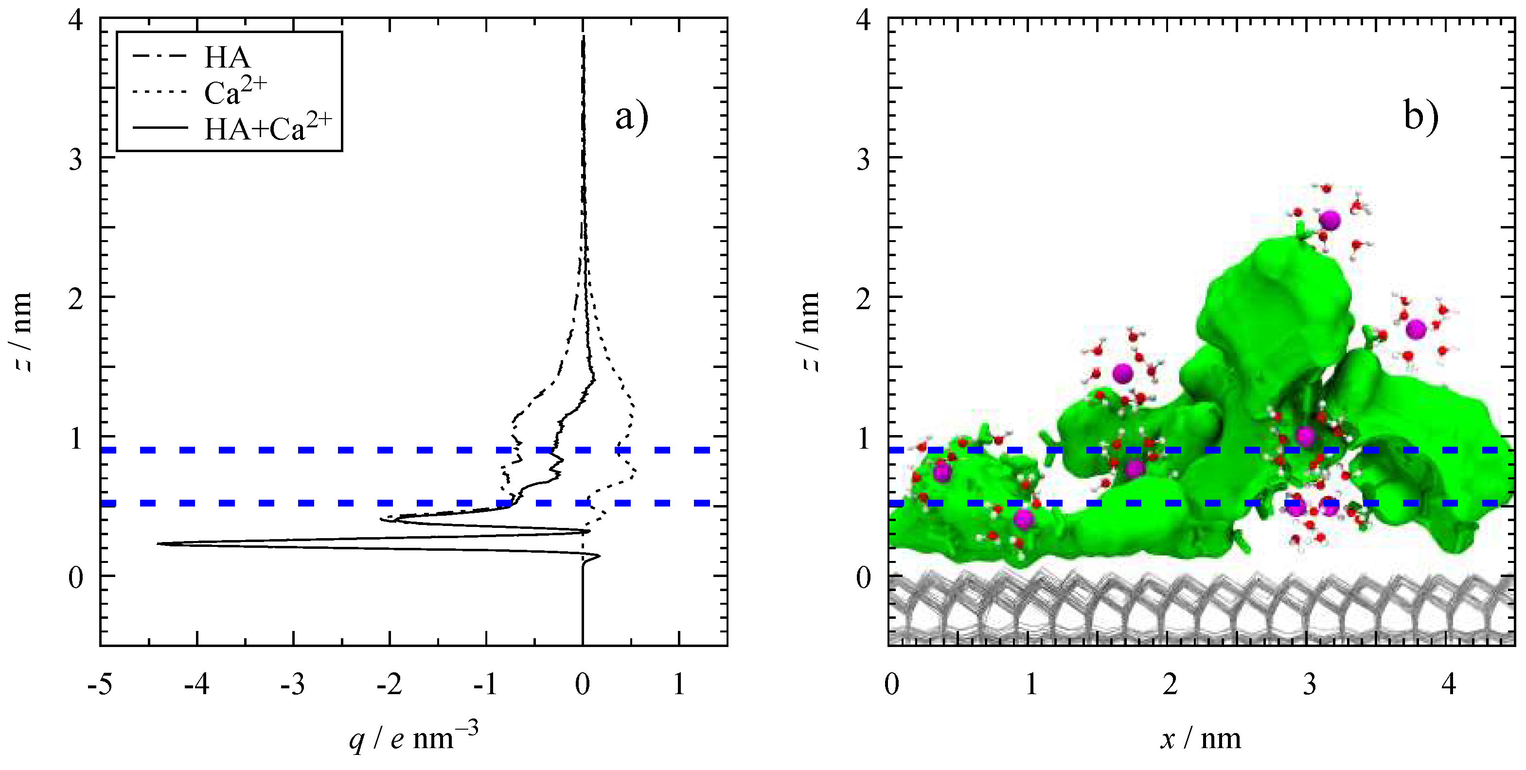
The preferential adsorption of HA and Ca2+ leads to polarization effects that manifest themselves in electrostatic properties. In Figure 3, we show the charge density profile, q, of HAs and Ca2+ on the aluminol side of the pore.
While the HA maximum located at z = 0.14 nm corresponded to donated protons to the aluminol surface, the first minimum at z = 0.23 nm corresponded to HAs proton acceptors. The high intensity of the minimum (Figure 3a) and the snapshot image (Figure 3b) suggested that HA molecular species adsorbed mostly in a parallel configuration to the surface. This orientation exposed most of the negatively charged HA atoms to the surface. Moreover, the HAs second minimum coincided with Ca–z1, confirming interactions between negatively charged HA sites and Ca2+. The negatively charged constant wide region in 0.57 < z < 1.13 nm suggested that HA fragments far from the aluminol surface were positionally flexible, contrarily to HA atoms in the vicinity of the surface.
The adsorption of Ca2+ cations (counterions) on the aluminol side confirmed ion–pairing interactions, which resulted in CaBs. The q values of Ca2+s second and third peaks showed similar affinity. Furthermore, the exposure of HAs bridging groups, such as COOs, not directly adsorbed to the surface broadened the width of the Ca2+‘s third peak (Ca–z3 = 1.21 nm).
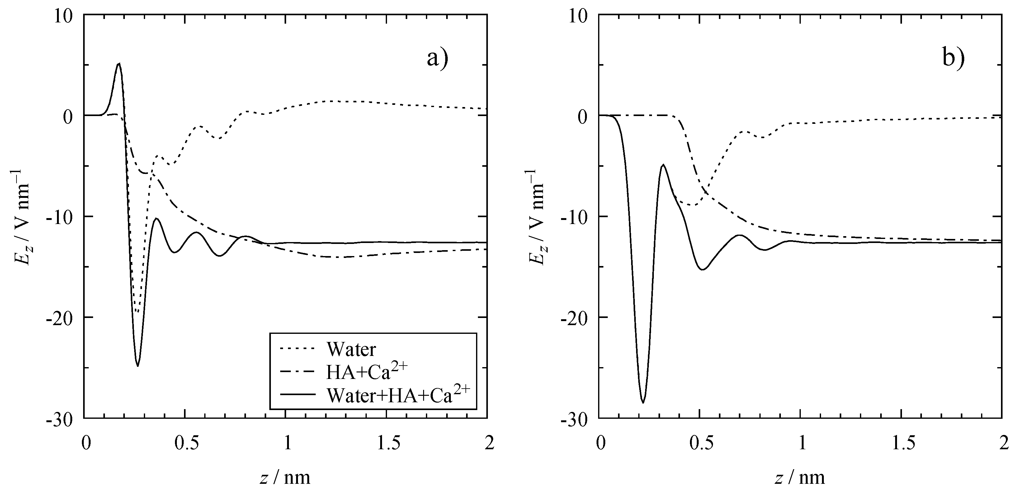
In our previous work [43], we proved that the presence of periodic dipolar interfaces confining water molecules induces an electric field. As a response, water molecules align their dipole moments parallel to the induced electric field, i.e., perpendicular to the surface. This preferential orientation is reflected by the electric field, Ez, of the confined solution obtained by Gauss’s law (Figure 4).
The contribution of water to Ez is relevant in the vicinity of both the aluminol (Figure 4a) and siloxane surfaces (Figure 4b). Ez, due to water, oscillates strongly close to both surfaces and levels–off to zero at distances greater than ~1.0 nm from any of the surfaces. Such behavior confirms preferential water orientation close to the surface but random orientation (bulk–like) far from surfaces. In contrast, the adsorption of ions (HA and Ca2+) promotes a drop in Ez, which remains constant in the middle of the cavity. Furthermore, the adsorption of ions results in a screening of the induced electric field, as noted in our previous work for the CsCl solution confined in the kaolinite nanopore [43].

3.4. Microscopic Structure

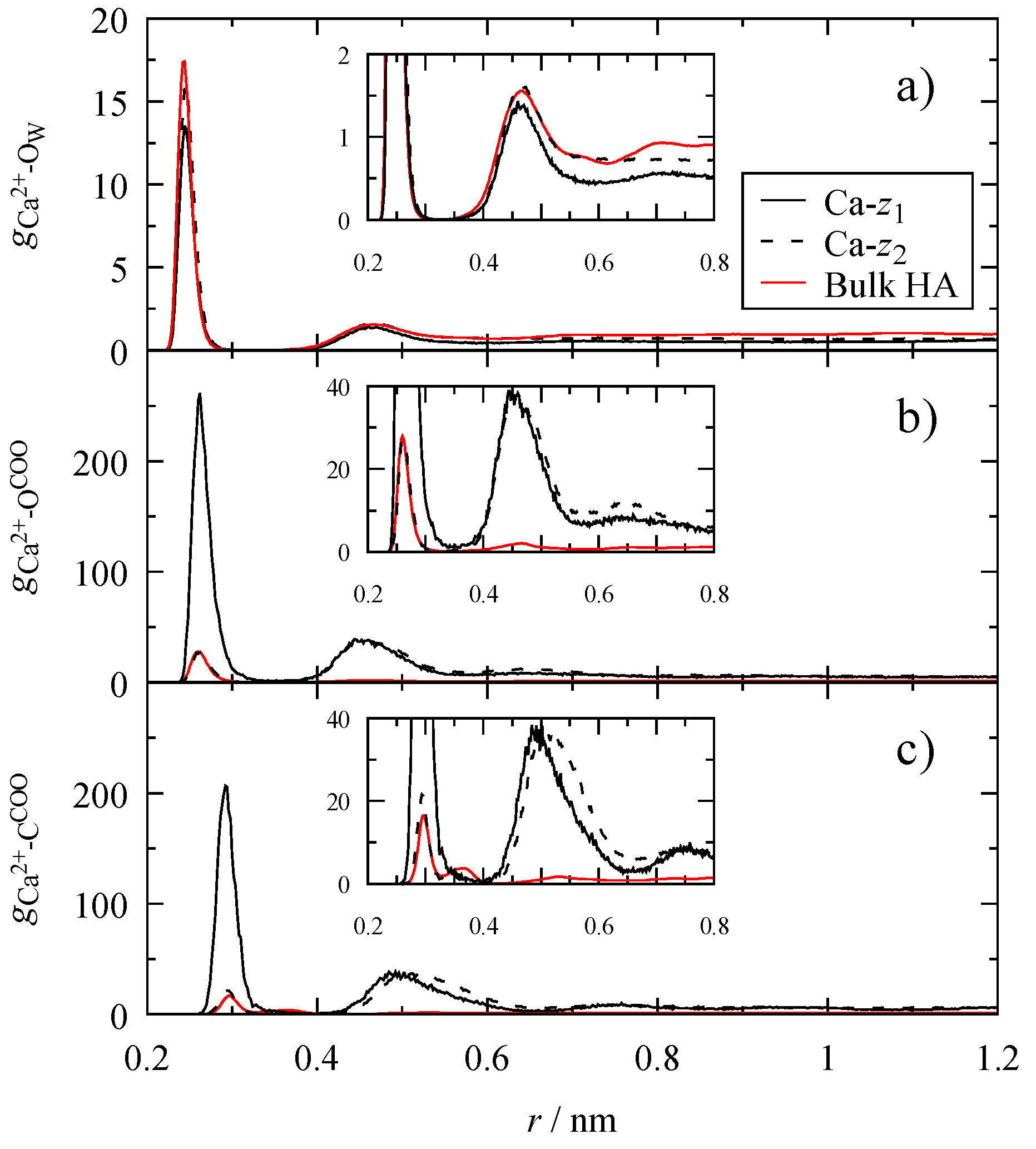
Further, we explored the effect of two kaolinite surfaces in the surrounding environment of Ca2+ cations in the vicinity of the aluminol surface by using the radial distribution functions (RDFs). Figure 5 displays the RDFs of Ca2+ in the regions Ca–z1 and Ca–z2 (for definition, see Figure 2) exhibiting some differences with respect to the Ca2+ RDFs in a bulk HA matrix (discussed in detail in our previous work) [20].
The peaks shown in Figure 5a correspond to the solvation shells around Ca2+ cations in different regions with a minimal difference between them. The first hydration shell observed was able to mediate the formation of OSCs cation bridges, as detailed by Galicia–Andrés et al. [20]. Moreover, in Figure 5b, the Ca2+–OCOO peaks exhibited the presence of the coordination shells at r = 0.26 and 0.45 nm that are characteristic for ISCs and OSCs, respectively. However, monodentate ISCs (ISC(m)) structures could not be discriminated, as both oxygens were distributed in the first and second coordination shells. The change in the distribution of complex structures was reflected by the change in the trend of the RDFs at different positions. The first coordination shell exhibited a higher intensity than the second coordination shell at Ca–z1, being opposite to the behavior at Ca–z2. On the other hand, Ca2+–CCOO RDFs could discern between ISC(m) and bidentate ISCs (ISC(b)) (Figure 5c). The lack of the peak at r = 0.37 nm implied that no ISCs(m) were present. Similarly, the first and second coordination shells exhibited an increased preference for OSCs at Ca–z2.
Table 1 reports the characteristic distances for complex structures and corresponding complex distribution, Keq, obtained from Equation (2) for the pair Ca2+–CCOO. For Ca–z1, a Keq ratio of ISC(b) to OSC 1:2 exhibits a major presence of OSCs in adsorbed HAs compared to the bulk HA matrix. At far distances (Ca–z2) the CaBs formed are almost exclusively OSCs. Therefore, the type of CaBs changes with respect to the distance from the aluminol surface.
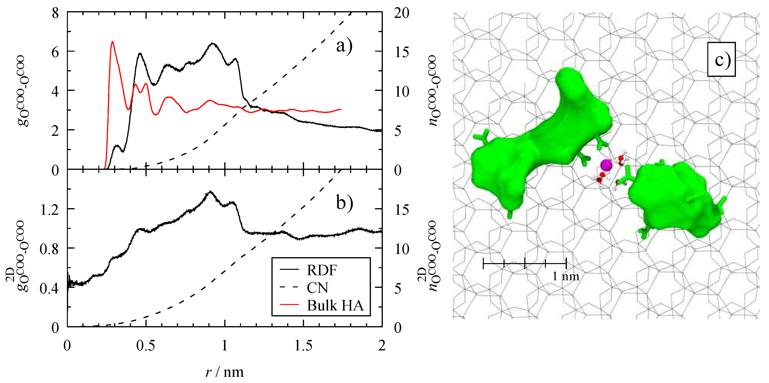
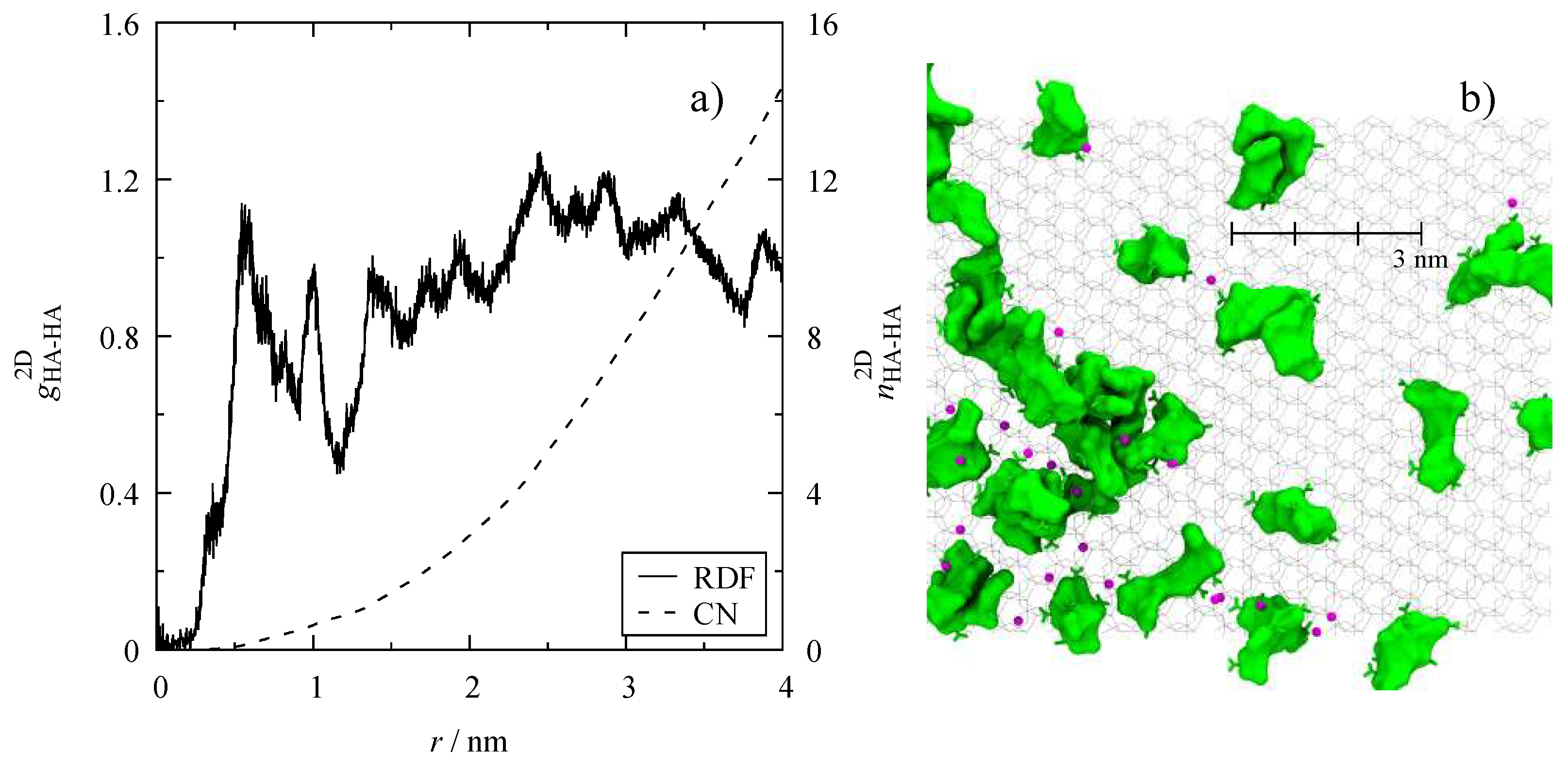
To quantify how HAs are distributed on the aluminol surface, Figure 6 shows the RDFs of the main functional groups responsible for the formation of CaBs (COOs). Only groups confined in the HA–z monolayer (adsorbed HAs) are included. In Figure 6a, a decrease in the intensity of the first coordination shell and an increase in the region 0.46 < r < 1.07 nm suggest that COOs are more separated from each other than in the bulk HA matrix. Unlike conventional RDFs, the 2D projection on the xy–plane, gij2D(r) (Figure 6b), exhibits the overlap of COOs, i.e., gij2D(0) ≈ 0.44. This overlap indicates the formation of aggregates in any direction, either parallel or perpendicular to the surface. Moreover, the plateau achieved at long distances means that COO ordering is local, i.e., r < 1.15 nm, with a mean value of ~9.5 COO’s oxygen atoms per carboxylate group. The mean coordination number accounts for COOs of either the same or different HA molecules.
Contrary to Figure 6, the xy–projection of HA’s center of mass (COM) RDF does not level off at distances bigger than 1 nm (Figure 7a). This behavior exhibits long-range structures of HAs adsorbed on the aluminol surface. These structures are formed due to repulsion interactions of electrostatic nature in the absence of CaBs (Figure 7b). The repulsion limits the number of adsorbed molecules on the surface close to each other.
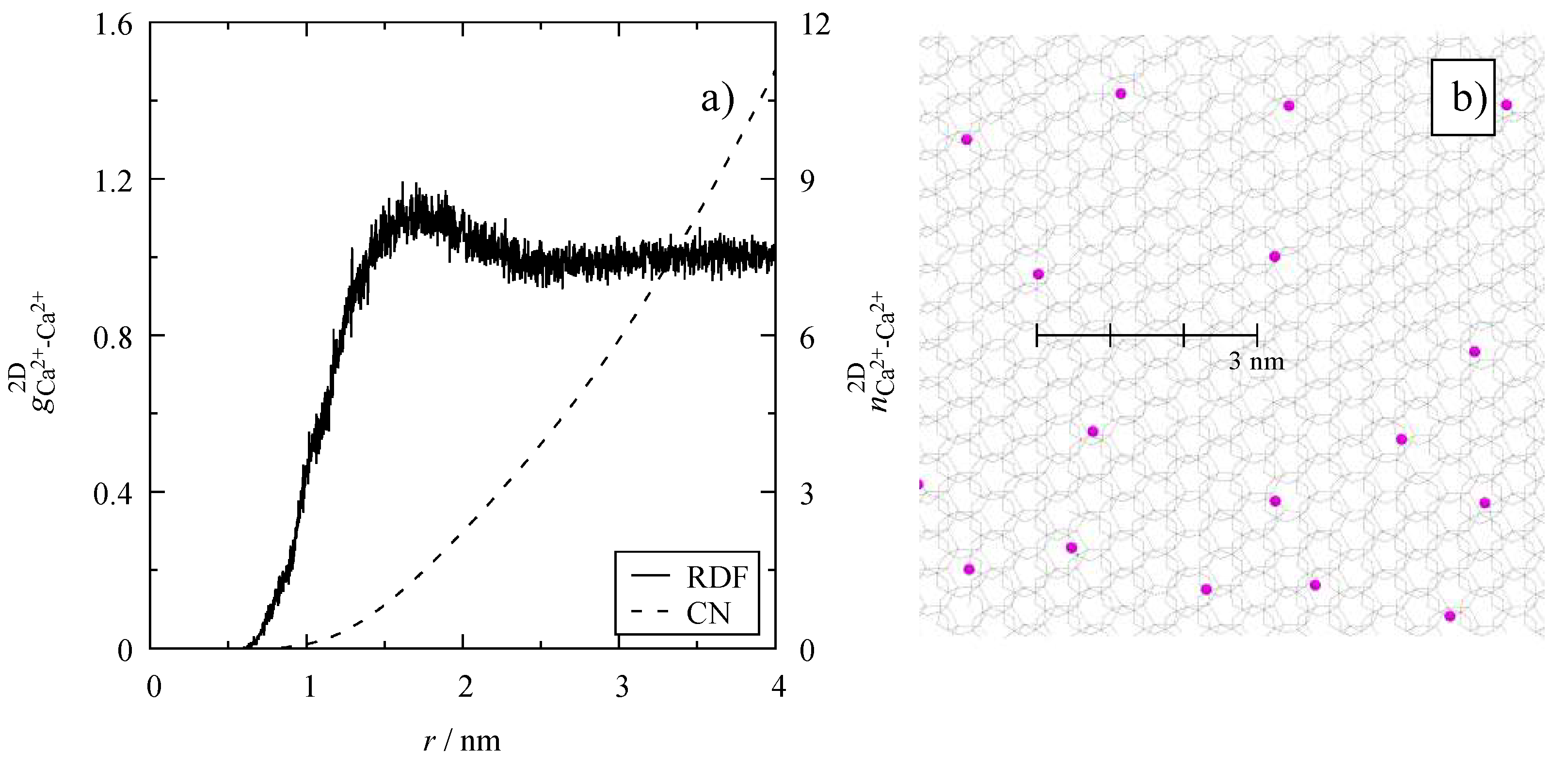
On the siloxane side, the Ca2+ cations adsorbed via OSCs exhibited an order at r < 2.3 nm with a mean coordination number ~3.2 (Figure 8a). In contrast to HA’s COMs, Ca2+ order was clearly defined due to the exclusive presence of cations and the symmetric nature of their repulsive interactions.

4. Discussion

4.1. Influence of Kaolinite on HA Aggregates

Newer concepts regarding the understanding of soil nature, such as the soil continuum model (SCM), consider the formation of supramolecular structures mimicking large molecules [2,58]. This makes the selection of LHA aggregates as representatives of SOMs consistent with long–standing concepts and new insights into soil. Similarly, it was shown that stable supramolecular structures break into fragments when interacting with reactive surfaces in a reversible process [40,41]. This allows the organic matter to stabilize and/or be protected from biochemical attack, explaining in part the persistence of carbon in soil aggregates [58].
The physicochemical properties of SOM aggregates with mineral surfaces, the type of aggregates, and the microscopic structure of particles depend on the intermolecular interactions with clay minerals such as kaolinite [59,60,61]. In previous works [62,63,64], atomic force microscopy (AFM) helped to show that the basal planes of kaolinite have a surface charge dependency with varying pH. Gupta and Miller [63] concluded that the iso–electric point (IEP) of the silica and alumina surfaces is at pH ~4 and between 6 and 8, respectively. Therefore, at circumneutral soil conditions, kaolinite has a positive charge density on the aluminol side and a negative charge density on the siloxane side. These electrostatic interactions, together with van der Waals interactions, are responsible for the formation and stability of aggregates of clay particles. If repulsive forces dominate clay particle interactions, they will repel each other. Hence, clay particles are led to a slow independent settlement that disperses them and causes a face–to–face orientation (booklets) [59,65]. When multiple layers stack one over the other, cavities and (nano)pores are formed and molecules in solution can be confined inside these cavities.
In this work, a model of OM in an aqueous medium was confined in a (nano)pore by a periodic kaolinite layer, mimicking stacked platelets. It has been proven previously that a periodic layering of kaolinite layers with a confined slab of water induces an electric field [43,66,67]. This electric field is responsible for the ideal polarizable electrode behavior of the model, similar to a capacitor [34,36]. Such behavior promotes the polarization of confined molecules having an impact on the adsorption of SOM and counterions on kaolinite exposed surfaces (Figure 2). By allowing the HA and Ca2+ cations to adsorb from the middle of the cavity to the aluminol and siloxane surfaces, we identified three main processes:
  • Disaggregation and separation of the supramolecular structure (HA and Ca2+ desorption);
  • HA (Ca2+) fixation on the aluminol (siloxane) surface;
  • HA (Ca2+) dispersion on the aluminol (siloxane) surface.
These processes occur in two steps, observed as two slopes in Figure 1a,b. In the first step, the dissociation and fixation occur simultaneously. Both depend on the degree of polarization of the surrounding environment (induced electric field). In the second step, the dispersion of OM occurs once the local structure of aggregates starts to develop, forming the electric double layer, EDL. Hence, polarization is responsible for the aggregate’s destruction (Figure 1c,d,e); if the polarization is removed, the supramolecular structure is held together by H–bonds and CaBs [40,41], in agreement with Piccolo’s OM aggregates theory [17].

4.2. Polarization of the Cavity

Although the induced electric field exacerbates polarization effects, it provides an idea of the dominating phenomena responsible for the adsorption and occlusion of SOM. Polarization depends on several factors such as the width of the aggregate that forms a single platelet particle, the thickness of the booklet arrangement, the interparticle space (width of nanopore), etc. However, in simulations, polarization can be controlled directly by removing the polarization and adding an external electric field; or indirectly by adjusting the width of the pore, the number of layers forming the particle, or the height of the vacuum separating the periodic images [43]. Tuning the polarization alters the amount of adsorbed species and their adsorption strength, and hence the development of EDL.
Two different interfaces are present in our nanopore model. These interfaces determine the EDL structures present on the model with two Stern layers at each surface and a diffuse layer shared in the middle of the cavity. On the aluminol side of the cavity, the main feature is the adsorption of HAs and Ca2+. The width of HAs monolayer (Figure 2a) and the position at which the sum of HA and Ca2+ charge are zero (Figure 3) coincide approximately at z = 1.2; therefore, the concentration of adsorbed molecules can be expressed either in terms of HAs amount (0.35 mol nm−2) or as total charge (–0.77 e nm−2). On the siloxane side, Ca2+ cations are adsorbed exclusively via OSCs with a concentration of 0.47 e nm−2 (Figure 2b).
The adsorption of HAs and Ca2+s on both sides of the surface produces an electric field, Ez, in the solution (Figure 4). This electric field, opposite to the direction of the induced electric field, is responsible for the screening effect. Consequently, the water molecules are randomly oriented in the middle of the cavity with no contribution to the field. In Figure 4, Ez shows that far from the aluminol or siloxane surfaces, the model exhibits a constant electric field, typical of parallel–plate capacitors. A particular feature of these capacitors is the linear increase of the electrostatic potential from the lowest (negatively charged) to the highest (positively charged) potential surface, as shown by Galicia–Andrés et al. [43] in Figure 6c for a [CsCl] = 1 M solution; however, by applying the sign convention of exerted work on the electrostatic potential of the confined solution, the slope is opposite in sign.

4.3. Electrical Double Layer (EDL)

In the previous sections, we discussed how polarization affects the extent of the supramolecular stability and the amount of adsorbed species. These consequences are also reflected in the development of the EDL.
On the siloxane side, adsorbed Ca2+ cations exhibit a simple structure on the surface (Figure 8). In Figure 2a, the relative position of adsorbed Ca2+ with respect to water molecules implies the formation of OSCs with the surface. This behavior indicates their affinity to remain solvated, resulting in a reservoir of cations that can be detached from the surface either to compensate the charge on the aluminol surface, to form CaBs with HAs, or to combine with other species present in the solution.
On the aluminol side, the original large HAs aggregate disintegrates partly to individual molecules and/or smaller subaggregates that are adsorbed at the surface, exposing as many negatively charged atoms as possible (Figure 3). The HA aggregates that remained during the adsorption process are held by CaBs. These aggregates, formed by HAs and Ca2+ cations, compensate for the partial positive charge from the aluminol surface.
Throughout the adsorption layer of HAs, three regions with different Ca2+ adsorption were observed. The first Ca2+ monolayer is repelled due to electrostatic interactions with the aluminol surface; however, HAs atoms with a negative charge, unable to interact with the surface due to steric effects, are able to “entrap” Ca2+ cations, maintaining the integrity of the aggregate. At farther distances, HAs are more mobile and the polarization decreases because the surface screening takes relevance. This explains the increase in Ca2+ concentration at the second and third monolayers. The width of Ca2+s third monolayer evidences the available region for molecular sorption. This region provides HA active sites (either COO/COOHs or hydrophobic sites) of adsorbed molecules and free from the influence of kaolinite polarization. As HAs are strongly adsorbed due to polarization effects, these structures form the so–called organo–mineral aggregates, providing active sites for sorption of a wide variety of molecules.

4.4. Dispersion of Humic Substances

The proposed organo–mineral aggregate model suggests that HAs interact with Ca2+ either by ISC(b) or OSC in any direction (Figure 5). When comparing the Keq of adsorbed HAs with that in a bulk SOM matrix [20] (Table 1), we observed a decrease in ISC(b) structures. These results imply that adsorbed molecules form weaker CaBs due to the influence of polarization effects, unlike adsorbed HAs in an unpolarized environment that reform the supramolecular aggregate [40]. Another consequence of the polarization is that at far distances, ISCs decrease considerably through the HA adsorption layer. As OSCs form weaker structures, HAs far from the surface are more mobile. Nonetheless, adsorbed aggregates with HAs far from the surface are prone to be dispersed more easily.
The distribution of Ca2+ on the aluminol surface and its relative position influence how HA species are dispersed on the surface. The dispersion of HAs is mainly due to repulsive interactions between COO groups until 1 nm (Figure 6a,b). Dispersed HAs exhibit long–range order responsible for the complex structuring of OM. This behavior is shown by the lack of convergence on the lateral RDF at great distances (Figure 7a). This result, together with the fact that there is no unique structure for HAs and their large conformational diversity, complicates the prediction of the measured structures.

5. Conclusions

In this work, we chose kaolinite as a typical soil mineral and leonardite humic acid as a representative of soil organic matter sample to model the most relevant SOM–mineral interactions in soil. Both are well–defined models which have been extensively studied both experimentally and computationally. The proposed kaolinite–SOM model helped to explain the adsorption mechanism of HSs on kaolinite surfaces that form structural cavities and pores. This is reflected in the disintegration of large SOM aggregates to smaller substructures that are better adsorbed on the aluminol surface. This adsorption process is enhanced by polarization effects typical of polar solutions confined in cavities and/or pores. The precursor stages of the adsorption of HSs were identified. The high content of HSs adsorbed on the active kaolinite surface explains the occlusion of HSs observed experimentally, which complicates its separation and quantification.
Polarization is reflected in the amount of adsorbed species on kaolinite surfaces, the development of the EDL, and the distribution of HSs on the kaolinite, which ultimately will determine the maximum saturation of the surface. HSs are adsorbed either as individual molecules resulting from the destruction of the original large supramolecular aggregate or as smaller subaggregates which are the remains of the original large supramolecular aggregate. These aggregate species are irregularly distributed over the (aluminol) surface forming patches at the surface.
In light of a more general conclusion, the capacitor–like behavior of kaolinite layers opens a possibility for its use in the development of novel materials in the fields of electrochemistry and materials science.

Author Contributions

Conceptualization, E.G.-A., C.O., M.H.G., and D.T.; formal analysis, E.G.-A.; writing–original draft, E.G.-A. and D.T.; writing–review and editing, E.G.-A., C.O., M.H.G., and D.T. All authors have read and agreed to the published version of the manuscript.

Funding

This research was funded by the Austrian Science Fund (FWF) Grant Numbers: P30224–N34; I4588–N and I3263–N34.

Acknowledgments

C.O. and E.G.-A. (project No. P30224–N34 and I4588–N), and D.T. (project No. I3263–N34) thank the Austrian Science Fund (FWF) for financial support. The computational results presented have been achieved in part using the Vienna Scientific Cluster (VSC) under the projects “Application of computer simulation for soil bioremediation” No. 71170 and “Modeling of sorption processes at surfaces and interfaces of minerals and organoclays” No. 70544. The authors thank the members of the Institute of Molecular Modeling and Simulation (MMS) and the Institute of Soil Research (IBF) for fruitful discussions.

Conflicts of Interest

The authors declare no conflict of interest.

References

  1. Baldock, J.A.; Broos, K. Soil organic matter. In Handbook of Soil Science: Properties and Processes; Huang, P.M., Li, Y., Summer, M.E., Eds.; CRC Press: Boca Raton, FL, USA, 2012; p. 1442. ISBN 978-1-4398-0306-6. [Google Scholar]
  2. Lehmann, J.; Kleber, M. The contentious nature of soil organic matter. Nature 2015, 528, 60–68. [Google Scholar] [CrossRef]
  3. Kleber, M. What is recalcitrant soil organic matter? Environ. Chem. 2010, 7, 320–332. [Google Scholar] [CrossRef]
  4. Totsche, K.U.; Amelung, W.; Gerzabek, M.H.; Guggenberger, G.; Klumpp, E.; Knief, C.; Lehndorff, E.; Mikutta, R.; Peth, S.; Prechtel, A.; et al. Microaggregates in soils. J. Plant Nutr. Soil Sci. 2018, 181, 104–136. [Google Scholar] [CrossRef] [Green Version]
  5. Baldock, J.A.; Skjemstad, J.O. Role of the soil matrix and minerals in protecting natural organic materials against biological attack. Org. Geochem. 2000, 31, 697–710. [Google Scholar] [CrossRef]
  6. Vrdoljak, G.; Sposito, G. Soil aggregate hierarchy in a Brazilian oxisol. In Developments in Soil Science; Elsevier: Amsterdam, The Netherlands, 2002; pp. 197–217. [Google Scholar]
  7. Tisdall, J.M.; Oades, J.M. Organic matter and water–stable aggregates in soils. J. Soil Sci. 1982, 33, 141–163. [Google Scholar] [CrossRef]
  8. Six, J.; Conant, R.T.; Paul, E.A.; Paustian, K. Stabilization mechanisms of soil organic matter: Implications for C–saturation of soils. Plant Soil 2002, 241, 155–176. [Google Scholar] [CrossRef]
  9. Schmidt, M.W.I.; Torn, M.S.; Abiven, S.; Dittmar, T.; Guggenberger, G.; Janssens, I.A.; Kleber, M.; Kögel–Knabner, I.; Lehmann, J.; Manning, D.A.C.; et al. Persistence of soil organic matter as an ecosystem property. Nature 2011, 478, 49–56. [Google Scholar] [CrossRef] [Green Version]
  10. Kleber, M.; Sollins, P.; Sutton, R. A conceptual model of organo–mineral interactions in soils: Self–assembly of organic molecular fragments into zonal structures on mineral surfaces. Biogeochemistry 2007, 85, 9–24. [Google Scholar] [CrossRef]
  11. Kleber, M.; Eusterhues, K.; Keiluweit, M.; Mikutta, C.; Mikutta, R.; Nico, P.S. Mineral–organic associations: Formation, properties, and relevance in soil environments. Adv. Agron. 2015, 130, 1–140. [Google Scholar]
  12. Newcomb, C.J.; Qafoku, N.P.; Grate, J.W.; Bailey, V.L.; De Yoreo, J.J. Developing a molecular picture of soil organic matter–mineral interactions by quantifying organo–mineral binding. Nat. Commun. 2017, 8, 396. [Google Scholar] [CrossRef]
  13. Aquino, A.J.A.; Tunega, D.; Schaumann, G.E.; Haberhauer, G.; Gerzabek, M.H.; Lischka, H. The functionality of cation bridges for binding polar groups in soil aggregates. Int. J. Quantum Chem. 2011, 111, 1531–1542. [Google Scholar] [CrossRef]
  14. Aquino, A.J.A.; Tunega, D.; Schaumann, G.E.; Haberhauer, G.; Gerzabek, M.H.; Lischka, H. Stabilizing capacity of water bridges in nanopore segments of humic substances: A theoretical investigation. J. Phys. Chem. C 2009, 113, 16468–16475. [Google Scholar] [CrossRef]
  15. Mouvenchery, Y.K.; Kučerík, J.; Diehl, D.; Schaumann, G.E. Cation–mediated cross–linking in natural organic matter: A review. Rev. Environ. Sci. Biotechnol. 2012, 11, 41–54. [Google Scholar] [CrossRef]
  16. Mouvenchery, Y.K.; Jaeger, A.; Aquino, A.J.A.; Tunega, D.; Diehl, D.; Bertmer, M.; Schaumann, G.E. Restructuring of a peat in interaction with multivalent cations: Effect of cation type and aging time. PLoS ONE 2013, 8, e65359. [Google Scholar] [CrossRef] [PubMed] [Green Version]
  17. Piccolo, A. The supramolecular structure of humic substances. Soil Sci. 2001, 166, 810–832. [Google Scholar] [CrossRef] [Green Version]
  18. Schaumann, G.E.; Bertmer, M. Do water molecules bridge soil organic matter molecule segments? Eur. J. Soil Sci. 2008, 59, 423–429. [Google Scholar] [CrossRef]
  19. Tunega, D.; Aquino, A.J.A.; Haberhauer, G.; Lischka, H.; Schaumann, G.E.; Gerzabek, M.H. Molecular models of cation and water molecule bridges in humic substances. In Soil Carbon; Hartemink, A., McSweeney, K., Eds.; Springer International Publishing: Cham, Switzerland, 2014; pp. 107–115. [Google Scholar]
  20. Galicia–Andrés, E.; Escalona, Y.; Oostenbrink, C.; Tunega, D.; Gerzabek, M.H. Soil organic matter stabilization at molecular scale: The role of metal cations and hydrogen bonds. Geoderma 2021, 401, 115237. [Google Scholar] [CrossRef]
  21. US Geological Survey. Characterization of the International Humic Substances Society Standard and Reference Fulvic and Humic Acids by Solution State Carbon–13 (13C) and Hydrogen–1 (1H) Nuclear Magnetic Resonance Spectrometry; U.S. Dept. of the Interior, U.S. Geological Survey: Books and Open–File Reports Section: Denver, CO, USA, 1989.
  22. Schaumann, G.E. Soil organic matter beyond molecular structure Part I: Macromolecular and supramolecular characteristics. J. Plant Nutr. Soil Sci. 2006, 169, 145–156. [Google Scholar] [CrossRef]
  23. Ai, Y.; Zhao, C.; Sun, L.; Wang, X.; Liang, L. Coagulation mechanisms of humic acid in metal ions solution under different pH conditions: A molecular dynamics simulation. Sci. Total Environ. 2020, 702, 135072. [Google Scholar] [CrossRef]
  24. Iskrenova–Tchoukova, E.; Kalinichev, A.G.; Kirkpatrick, R.J. Metal cation complexation with natural organic matter in aqueous solutions: Molecular dynamics simulations and potentials of mean force. Langmuir 2010, 26, 15909–15919. [Google Scholar] [CrossRef] [Green Version]
  25. Kalinichev, A.G.; Iskrenova–Tchoukova, E.; Ahn, W.Y.; Clark, M.M.; Kirkpatrick, R.J. Effects of Ca2+ on supramolecular aggregation of natural organic matter in aqueous solutions: A comparison of molecular modeling approaches. Geoderma 2011, 169, 27–32. [Google Scholar] [CrossRef] [Green Version]
  26. Kalinichev, A.G.; Kirkpatrick, R.J. Molecular dynamics simulation of cationic complexation with natural organic matter. Eur. J. Soil Sci. 2007, 58, 909–917. [Google Scholar] [CrossRef]
  27. Tan, L.; Yu, Z.; Tan, X.; Fang, M.; Wang, X.; Wang, J.; Xing, J.; Ai, Y.; Wang, X. Systematic studies on the binding of metal ions in aggregates of humic acid: Aggregation kinetics, spectroscopic analyses and MD simulations. Environ. Pollut. 2019, 246, 999–1007. [Google Scholar] [CrossRef]
  28. Escalona, Y.; Petrov, D.; Oostenbrink, C. Vienna soil organic matter modeler 2 (VSOMM2). J. Mol. Graph. Model. 2021, 103, 107817. [Google Scholar] [CrossRef]
  29. Sündermann, A.; Solc, R.; Tunega, D.; Haberhauer, G.; Gerzabek, M.H.; Oostenbrink, C. Vienna Soil-Organic-Matter Modeler—Generating condensed–phase models of humic substances. J. Mol. Graph. Model. 2015, 62, 253–261. [Google Scholar] [CrossRef] [Green Version]
  30. Ritschel, T.; Totsche, K.U. Modeling the formation of soil microaggregates. Comput. Geosci. 2019, 127, 36–43. [Google Scholar] [CrossRef]
  31. Loganathan, N.; Ferguson, B.O.; Arey, B.; Argersinger, H.E.; Bowers, G.M. A Mechanistic Exploration of Natural Organic Matter Aggregation and Surface Complexation in Smectite Mesopores. J. Phys. Chem. A 2020, 124, 9832–9843. [Google Scholar] [CrossRef]
  32. Zhang, Y.; Liu, X.; Zhang, C.; Lu, X. A combined first principles and classical molecular dynamics study of clay–soil organic matters (SOMs) interactions. Geochim. Cosmochim. Acta 2020, 291, 110–125. [Google Scholar] [CrossRef]
  33. Schmickler, W.; Santos, E. Interfacial Electrochemistry; Springer: Berlin/Heidelberg, Germany, 2010; ISBN 978-3-642-04936-1. [Google Scholar]
  34. Zhang, C. Note: On the dielectric constant of nanoconfined water. J. Chem. Phys. 2018, 148, 156101. [Google Scholar] [CrossRef] [Green Version]
  35. Sayer, T.; Zhang, C.; Sprik, M. Charge compensation at the interface between the polar NaCl(111) surface and a NaCl aqueous solution. J. Chem. Phys. 2017, 147, 104702. [Google Scholar] [CrossRef] [PubMed]
  36. Zhang, C.; Sprik, M. Computing the dielectric constant of liquid water at constant dielectric displacement. Phys. Rev. B 2016, 93, 144201. [Google Scholar] [CrossRef] [Green Version]
  37. Petrov, D.; Tunega, D.; Gerzabek, M.H.; Oostenbrink, C. Molecular dynamics simulations of the standard Leonardite humic acid: Microscopic analysis of the structure and dynamics. Environ. Sci. Technol. 2017, 51, 5414–5424. [Google Scholar] [CrossRef] [PubMed]
  38. Petrov, D.; Tunega, D.; Gerzabek, M.H.; Oostenbrink, C. Molecular modelling of sorption processes of a range of diverse small organic molecules in Leonardite humic acid. Eur. J. Soil Sci. 2020, 71, 831–844. [Google Scholar] [CrossRef] [Green Version]
  39. Escalona, Y.; Petrov, D.; Oostenbrink, C. Modeling Soil Organic Matter: Changes in Macroscopic Properties due to Microscopic Changes. Geochim. Cosmochim. Acta 2021, 307, 228–241. [Google Scholar] [CrossRef]
  40. Gerzabek, M.H.; Tunega, D.; Galicia–Andrés, E.; Oostenbrink, C. Soil organic matter and molecular simulations (Accepted). In Encyclopedia of Soils in the Environment; Staunton, S., Xing, B., Eds.; Elsevier: Amsterdam, The Netherlands, 2021. [Google Scholar]
  41. Galicia–Andrés, E.; Grančič, P.; Gerzabek, M.H.; Oostenbrink, C.; Tunega, D. Modeling of interactions in natural and synthetic organoclays. In Computational Modeling in Clay Mineralogy; Sainz Diaz, I.C., Ed.; Digilabs: Bari, Italy, 2021; pp. 211–254. ISBN 978-88-7522-048-8. [Google Scholar]
  42. Bish, D.L. Rietveld refinement of the kaolinite structure at 1.5 K. Clays Clay Miner. 1993, 41, 738–744. [Google Scholar] [CrossRef]
  43. Galicia–Andrés, E.; Petrov, D.; Gerzabek, M.H.; Oostenbrink, C.; Tunega, D. Polarization effects in simulations of kaolinite–water interfaces. Langmuir 2019, 35, 15086–15099. [Google Scholar] [CrossRef] [PubMed]
  44. Galicia–Andrés, E.; Tunega, D.; Gerzabek, M.H.; Oostenbrink, C. On glyphosate–kaolinite surface interactions. A molecular dynamic study. Eur. J. Soil Sci. 2021, 72, 1231–1242. [Google Scholar] [CrossRef] [PubMed]
  45. Schmid, N.; Eichenberger, A.P.; Choutko, A.; Riniker, S.; Winger, M.; Mark, A.E.; Van Gunsteren, W.F. Definition and testing of the GROMOS force–field versions 54A7 and 54B7. Eur. Biophys. J. 2011, 40, 843–856. [Google Scholar] [CrossRef]
  46. Vasconcelos, I.F.; Bunker, B.A.; Cygan, R.T. Molecular Dynamics Modeling of Ion Adsorption to the Basal Surfaces of Kaolinite. J. Phys. Chem. C 2007, 111, 6753–6762. [Google Scholar] [CrossRef]
  47. Cygan, R.T.; Liang, J.-J.; Kalinichev, A.G. Molecular models of hydroxide, oxyhydroxide, and clay phases and the development of a general force field. J. Phys. Chem. B 2004, 108, 1255–1266. [Google Scholar] [CrossRef]
  48. Berendsen, H.J.C.; Postma, J.P.M.; van Gunsteren, W.F.; Hermans, J. Interaction models for water in relation to protein hydration. In Intermolecular Forces, Proceedings of the Fourteenth Jerusalem Symposium on Quantum Chemistry and Biochemistry Held in Jerusalem, Israel, 13–16 April 1981; Pullman, B., Ed.; Springer: Dordrecht, The Netherlands, 1981; pp. 331–342. ISBN 978-94-015-7658-1. [Google Scholar]
  49. Abraham, M.J.; Murtola, T.; Schulz, R.; Páll, S.; Smith, J.C.; Hess, B.; Lindahl, E. GROMACS: High performance molecular simulations through multi–level parallelism from laptops to supercomputers. SoftwareX 2015, 1–2, 19–25. [Google Scholar] [CrossRef] [Green Version]
  50. Berendsen, H.J.C.; Postma, J.P.M.; van Gunsteren, W.F.; DiNola, A.; Haak, J.R. Molecular dynamics with coupling to an external bath. J. Chem. Phys. 1984, 81, 3684–3690. [Google Scholar] [CrossRef] [Green Version]
  51. Essmann, U.; Perera, L.; Berkowitz, M.L.; Darden, T.; Lee, H.; Pedersen, L.G. A smooth particle mesh Ewald method. J. Chem. Phys. 1995, 103, 8577–8593. [Google Scholar] [CrossRef] [Green Version]
  52. Linse, B.; Linse, P. Tuning the smooth particle mesh Ewald sum: Application on ionic solutions and dipolar fluids. J. Chem. Phys. 2014, 141, 184114. [Google Scholar] [CrossRef]
  53. Ewald, P.P. Die Berechnung optischer und elektrostatischer Gitterpotentiale. Ann. Phys. 1921, 369, 253–287. [Google Scholar] [CrossRef] [Green Version]
  54. Miyamoto, S.; Kollman, P.A. Settle: An analytical version of the SHAKE and RATTLE algorithm for rigid water models. J. Comput. Chem. 1992, 13, 952–962. [Google Scholar] [CrossRef]
  55. Hess, B.; Bekker, H.; Berendsen, H.J.C.; Fraaije, J.G.E.M. LINCS: A linear constraint solver for molecular simulations. J. Comput. Chem. 1997, 18, 1463–1472. [Google Scholar] [CrossRef]
  56. Humphrey, W.; Dalke, A.; Schulten, K. VMD: Visual molecular dynamics. J. Mol. Graph. 1996, 14, 33–38. [Google Scholar] [CrossRef]
  57. Rapaport, D.C. The Art of Molecular Dynamics Simulation; Cambridge University Press: Cambridge, UK, 2004. [Google Scholar]
  58. Lehmann, J.; Hansel, C.M.; Kaiser, C.; Kleber, M.; Maher, K.; Manzoni, S.; Nunan, N.; Reichstein, M.; Schimel, J.P.; Torn, M.S.; et al. Persistence of soil organic carbon caused by functional complexity. Nat. Geosci. 2020, 13, 529–534. [Google Scholar] [CrossRef]
  59. Ivanić, M.; Vdović, N.; Sandra Brito Baretto, D.; Bermanec, V.; Sondi, I. Mineralogy, surface properties and electrokinetic behaviour of kaolin clays from the naturally occurring pegmatite deposits. Geol. Croat. 2015, 68, 139–145. [Google Scholar] [CrossRef] [Green Version]
  60. Siretanu, I.; van den Ende, D.; Mugele, F. Atomic structure and surface defects at mineral–water interfaces probed by in situ atomic force microscopy. Nanoscale 2016, 8, 8220–8227. [Google Scholar] [CrossRef]
  61. Wang, G.; Ran, L.; Xu, J.; Wang, Y.; Ma, L.; Zhu, R.; Wei, J.; He, H.; Xi, Y.; Zhu, J. Technical development of characterization methods provides insights into clay mineral–water interactions: A comprehensive review. Appl. Clay Sci. 2021, 206, 106088. [Google Scholar] [CrossRef]
  62. Morais, L.; Cordão–Neto, M.; Tarantino, A. Aggregation process of kaolinite clay. E3S Web Conf. 2019, 92, 03002. [Google Scholar] [CrossRef]
  63. Gupta, V.; Miller, J.D. Surface force measurements at the basal planes of ordered kaolinite particles. J. Colloid Interface Sci. 2010, 344, 362–371. [Google Scholar] [CrossRef] [PubMed]
  64. Gupta, V.; Hampton, M.A.; Stokes, J.R.; Nguyen, A.V.; Miller, J.D. Particle interactions in kaolinite suspensions and corresponding aggregate structures. J. Colloid Interface Sci. 2011, 359, 95–103. [Google Scholar] [CrossRef]
  65. Raj, P.P. Soil Mechanics and Foundation Engineering, 2nd ed.; Pearson: New Delhi, India, 2013; ISBN 9788131790816. [Google Scholar]
  66. Yeh, I.-C.; Berkowitz, M.L. Dielectric constant of water at high electric fields: Molecular dynamics study. J. Chem. Phys. 1999, 110, 7935–7942. [Google Scholar] [CrossRef]
  67. Yeh, I.-C.; Berkowitz, M.L. Ewald summation for systems with slab geometry. J. Chem. Phys. 1999, 111, 3155–3162. [Google Scholar] [CrossRef]
Figure 1. Time series of the non–bonded interaction energy (Coulomb + Lennard–Jones 12–6) in the equilibration step of kaolinite (Kln) with humic acids (HAs) and calcium (a); and HAs with calcium (b). The slope change indicates a different process. Side view (xz–plane) of the dynamics of the HAs supramolecular structure (green isosurfaces) in the pore space between the two kaolinite surfaces (gray lines) at t = 0 (c), 10 (d), and 30 ns (e). Ca2+ cations are represented as magenta balls. For clarity, water molecules are not shown. The top layer represents the periodic image of kaolinite.
Minerals 11 01138 g001
Figure 2. Probability distribution, ρ, of the oxygen atom of water (OW), calcium cation (Ca2+) and humic acid center of mass (HA) as a function of the distance, z, from the aluminol (a) and siloxane surfaces (b). Basal oxygen atoms of both surfaces are taken as a reference position (z = 0). The maxima adsorption regions of Ca2+ and HA on the aluminol side are located at z = 0.44 (Ca–z1), z = 0.76 (Ca–z2), z = 1.21 (Ca–z3) and z = 0.56 nm (HA–z).
Minerals 11 01138 g002
Figure 3. Charge density profiles, q, of humic acid (HA), calcium (Ca2+), and their sum (HA+Ca2+) as a function of the distance, z, from the aluminol surface (a). Side view (xz–plane) of the simulation box exhibiting HAs (green isosurfaces) forming aggregates through cation bridges (b). Basal oxygen atoms of the surface are taken as a reference position (z = 0). The first, second, and third Ca2+ peaks are divided by dashed blue lines. Ca2+ cations are represented as magenta balls and the surrounding water molecules as balls and sticks. For clarity, all other water molecules are not shown.
Minerals 11 01138 g003
Figure 4. Electric field profiles, Ez, due to water, and to the sum of ions (HA+Ca2+) as well as the total electric field (Water+HA+Ca2+) as a function of the perpendicular distance, z, from the aluminol (a) and siloxane surfaces (b). Basal oxygen atoms of both surfaces are taken as a reference position (z = 0).
Minerals 11 01138 g004
Figure 5. Radial distribution functions (RDFs; gij) of calcium (Ca2+) with the water oxygen atoms (a), carboxylate oxygen (b), and carbon atoms (c) of humic acids on the aluminol side at distance r from the Ca2+ confined in two regions–Ca–z1 (0 < z1 < 0.5 nm) and Ca–z2 (0.5 < z2 < 0.9 nm). Black lines correspond to RDFs in this work, whereas red lines to those observed for Ca2+ in bulk HA matrix from Galicia–Andrés et al. [20], respectively.
Minerals 11 01138 g005
Figure 6. Conventional (a) and lateral (b) radial distribution functions (RDFs; gij) and running coordination numbers (CN) of carboxylate oxygen atoms of HAs on the aluminol side at distance r from the reference atom confined in HA–z (0 < z < 1.15 nm). The black and red lines correspond to the RDFs in this work and in a bulk HA matrix from Galicia–Andrés et al. [20], respectively. The red line is scaled three times for better visualization. Top view (xy–plane) of HAs patches (green isosurfaces) adsorbed on the aluminol surface of kaolinite (gray lines) and forming a cation bridge through the Ca2+ cation (magenta ball) (c).
Minerals 11 01138 g006
Figure 7. Lateral radial distribution function (RDF; gij) and running coordination number (CN) of HA’s COM on the aluminol side at distance r from the reference COM confined in 0 < z < 1.15 nm space (a). Top view (xy–plane) of HA patches (green isosurfaces) adsorbed on the aluminol surface of kaolinite (gray lines) (b). Ca2+ cations are presented as magenta balls.
Minerals 11 01138 g007
Figure 8. Lateral radial distribution function (RDF; gij) and integrated coordination number (CN) of Ca2+ cations on the siloxane side at distance r confined in 0 < z < 0.6 nm space (a). Top view (xy–plane) of Ca2+ cations (magenta balls) adsorbed on the siloxane surface of kaolinite (gray lines) (b).
Minerals 11 01138 g008
Table 1. Ca2+–CCOO RDF characteristic positions of the first and second maxima, ISC(b) and OSC, respectively; first and second minima, RL and RU, respectively; and complex distribution constant Keq.
PositionISC(b)/nmRL/nmOSC/nmRU/nmKeq
Ca–z10.290.400.480.622.14
Ca–z20.290.400.510.6623.83
HA matrix 10.300.430.530.640.99
1 Results reported for the bulk HA matrix [20].
Publisher’s Note: MDPI stays neutral with regard to jurisdictional claims in published maps and institutional affiliations.