Article

Gas Migration Patterns with Different Borehole Sizes in Underground Coal Seams: Numerical Simulations and Field Observations

1
School of Safety Engineering, China University of Mining and Technology, Xuzhou 221116, China
2
Wuhai Energy Co., Ltd., Wuhai 016033, China
3
School of Civil, Mining and Environmental Engineering, University of Wollongong, Wollongong 2500, Australia
*
Author to whom correspondence should be addressed.
Minerals 2021, 11(11), 1254; https://doi.org/10.3390/min11111254
Submission received: 15 October 2021 / Revised: 4 November 2021 / Accepted: 9 November 2021 / Published: 11 November 2021
(This article belongs to the Special Issue Minerals Impact on CO2 Geo-sequestration in Deep Reservoirs)

Abstract

:
Gas flow in a coal seam is a complex process due to the complicated coal structure and the sorption characteristics of coal to adsorbable gas (such as carbon dioxide and methane). It is essential to understand the gas migration patterns for different fields of engineering, such as CBM exploitation, underground coal mine gas drainage, and CO2 geo-sequestration. Many factors influence gas migration patterns. From the surface production wells, the in-seam patterns of gas content cannot be quantified, and it is difficult to predict the total gas production time. In order to understand the gas flow patterns during gas recovery and the gas content variations with respect to production time, a solid-fluid coupled gas migration model is proposed to illustrate the gas flow in a coal seam. Field data was collected and simulation parameters were obtained. Based on this model, different scenarios with different borehole sizes were simulated for both directional boreholes and normal parallel boreholes in coal seams. Specifically, the borehole sizes for the directional boreholes were 10 m, 15 m, and 20 m. The borehole sizes for the normal parallel boreholes were 2 m, 4 m, and 6 m. Under different gas drainage leading times, the total gas recovery and residual gas contents were quantified. In Longwall Panel 909 of the Wuhushan coal mine, one gas drainage borehole and five 4 m monitoring boreholes were drilled. After six months of monitoring, the residual gas content was obtained and compared with the simulation results. Of the total gas, 61.36% was drained out from the first 4 m borehole. In this field study, the effective drainage diameter of the drainage borehole was less than 8 m after six months of drainage. The gas drainage performance was tightly affected by the borehole size and the gas drainage time. It was determined that the field observations were in line with the simulation results. The findings of this study can provide field data for similar conditions.

1. Introduction

Coal seam gas (CSG), often referred to as coal bed methane (CBM), exists in underground coal seams [1]. In terms of natural gas production, it is a form of clean energy [2], but in terms of coal mining, coal seam gas brings a potential hazard for underground activities, such as coal and gas outbursts [3,4] or gas explosions. Due to the adsorption characteristics of coal seams, CO2 geo-sequestration is one possible method of disposing the excess greenhouse gases into the atmosphere [5,6].
The structures of coal seams have been studied by many scholars and, currently, it is widely accepted that the dual-porosity system is suitable for describing the coal porosity structure [7,8]. Coal blocks are cut by fractures or cleats, and coal seams consist of coal matrices and coal fractures. The fracture or cleat systems are the main gas flow channels [9], and the aperture is often larger than 100 nm. In other words, the pores in the coal seam that are larger than 100 nm contribute to the gas flow. Small pores exist in the coal matrix and most of the coal seam gas is stored in these small pores in an adsorption phase state [10]. The volume of the free phase state gas accounts for less than 10% of the total CSG. For the gas recovery process (the coal seam gas discharge process or gas drainage process), the adsorbed gas desorbs from the internal surface of the micropores and then diffuses into the coal fractures [11,12]. Then, these gas molecules flow through the fractures into boreholes or gas production wells [13]. Pores between 2 nm and 100 nm are usually mesopores, and gas diffusion occurs in these pores. The widely used model that describes this diffusion process is Fick’s diffusion law. The gas concentration in the coal matrix is the gas molecules’ moving driving force [14,15]. In the center of the coal matrix, the gas concentration is high. If mining activities disturb the coal seam, the initial balance is broken and gas migration happens. In gas flow channels (fractures/cleats), Darcy’s flow law is used to illustrate the gas flow. The gas flows towards the wells or boreholes due to the low gas pressure in the wells or boreholes [16,17].
Based on the dual-porosity structure of coal seams, permeability models have been proposed by scholars. During the gas recovery process, the reservoir experiences complex changes [18]. With the depletion of the reservoir, the gas pressure drops, while the in situ stress is kept constant. As a result, the effective stress of the reservoir increases, and the gas flow channels are compacted by the effective stress, decreasing the reservoir permeability. Regarding gas sorption, the depletion of the reservoir contributes to the desorption of gas. Many scholars have observed matrix swelling and shrinkage with respect to the adsorption and desorption of coal seam gas [19]. The coal matrix skeleton shrinks with the desorption of CBM and the permeability increases. In the production field, permeability is the combination of these two competing trends.
Numerical models have been proposed by scholars to investigate gas recovery in coal seams [20,21]. The fundamental theory of these models is similar. The gas storage in the coal seam obeys the gas adsorption laws, such as the Langmuir model. Gas seepage and diffusion are illustrated by Darcy’s law and Fick’s law [22], respectively, and the coal structure is considered. Other influencing factors, such as self-heating, have been considered in investigations of gas migration. Coal-gas heating interactions were investigated [23]. Based on the numerical models, the geomechanical characteristics during coal seam gas production were studied. The stress state, porosity variations, and gas production were investigated [24]. Most of these models are used to predict the gas production or variations during this process [25]. A large scale of the coal seams was simulated based on these models and the long-term production was predicted. The simulation results correspond with those of the field production, in terms of gas production. The detailed gas distribution patterns in the coal seam are not clear. Other engineering projects, such as CO2-enhanced coal bed methane recovery (CO2-ECBM), hydraulic fracturing, and well designs, have also been investigated through numerical simulations [26,27,28,29,30].
Laboratory tests were conducted to investigate coal permeability under different testing conditions (different gas types, gas pressure, and in situ stress). The correlations amongst these different factors were studied. After being compared with the laboratory testing results, the numerical models were validated and applied to different testing scenarios. One of the key issues of the laboratory testing was the boundary conditions or the size effect on the results. Due to the testing limitations, the size of the specimen was small, and the results did not fully replicate the field conditions. For example, under the same external confining stress conditions, the permeability was much lower in the laboratory testing, which did not correctly reflect the field production.
It is essential to do field observations of gas migration. Typically, the exploration of CBM is through the surface wellbores. It is much harder to observe the gas migration patterns of underground gas drainage in the underground coal mining industry. In underground mining workings, gas drainage work is widely conducted to reduce the coal seam gas content in order to reduce the outburst hazards [31,32]. Usually, for a longwall panel, the width is between 100 m and 300 m, and the length is more than 1 km. In some large coal mines, the length is over 3 km [33]. Underground in-seam boreholes are drilled into the roadways for gas drainage. These boreholes are parallel to each other or in fan patterns. The length of the boreholes can be as long as 1 km. For some monitoring boreholes, they can be shorter than 100 m.
In this study, coal samples were collected from underground workings and a series of laboratory testing and field tests were conducted to investigate the coal and gas characteristics. Based on these parameters, a numerical model was developed to study the gas migration in the coal seam. Different borehole size conditions were simulated. Based on the simulation results, the design of gas drainage boreholes was obtained and the gas drainage boreholes were drilled, after which field observations were carried out. By monitoring the gas content near the gas drainage boreholes, the gas drainage performance was evaluated and the gas migration patterns were obtained. The effective diameter of the borehole was determined, which can be useful for other engineering field applications. The findings of this study can also contribute to the applications of CO2 geo-sequestration.

2. Geological Settings

The field applications and observations were carried out in the Wuhushan coal mine, located in the Wuda coal mining area, Inner Mongolia, China. In this mining area, there are three coal seams, namely the No. 9 coal seam, the No. 10 coal seam, and the No. 12 coal seam. The current longwall panel is arranged in the No. 9 coal seam and the depth of cover is between 280 m and 360 m. The thickness of this layer ranges between 0.5 m and 4.4 m, with an average thickness of 2.8 m. The No. 10 coal seam is beneath the No. 9 coal seam, as shown in Figure 1. The gas content was relatively high (with an average content of 18.87 m3/t), and it showed an increasing trend as the depth increased. Structures and faults were detected in both seams, and the gas content can sharply rise in the fault area. Figure 1 shows the strata column of the coal seams. The No. 9 seam is close to the No. 10 seam. In both seams, the gas content was very high. The average gas content was 14.5 m3/t (virgin coal; the gas pressure refers to the original gas content.). During the coal mining process, gas drainage work is conducted to reduce the total gas content. The risk of coal and gas outbursts is reduced, as are gas emissions during the mining process, and the environment is protected.

3. Numerical Modelling

3.1. Basic Theory and Model Settings

Coal seam gas seepage is a complex process and many factors affect it. Seepage channels critically affect the gas migration patterns [34]. The dual-porosity system of the coal seam has a wide pore size range, from nanometers to micrometers [35,36]. The gaseous state is also complicated because the micropores can adsorb gas molecules. It is estimated that 90% of the total gas in coal seams exists in an adsorption phase state and only 10% is in a free phase state, which is quite different from that in a conventional natural gas reservoir. Even though Darcy’s law can be used to describe the gas seepage process, the gas conversion between different phase states should be considered [37,38,39,40].
In field cases, many factors can influence the gas seepage process, such as faults, structure, and adjacent rock layers. In order to find the key factors and guide field production, some simplifications were adopted, and we made several assumptions for the numerical modeling process, as follows.
Gas migration in the adjacent rock layers is very minor. In this study, it was assumed that gas seepage only occurs in the coal seam.
The permeability of the coal seam is governed by the porosity system. The porosity of the micropores is not affected by the gas pressure, meaning the matrix pores are not affected.
The temperature is constant during the gas seepage process and it is regarded as an isothermal process. The ideal gas law was applied and Darcy’s law was used to describe gas migrations.
u = ( K x μ p x i + K y μ p y j + K z μ p z k )
where K x , K y , and K z are the permeability in the x , y , and z directions, respectively. μ is the gas viscosity, and u is the gas flow velocity.
Gas pressure in the seam refers to the free phase gas pressure. Usually, near the working face or the underground gateways (affected by the roadway excavations), the gas pressure ranges between 0.1 MPa and 0.2 MPa. For intact coal seams, the levels of gas pressure are very similar at the same depth of the same seam. An abnormal gas pressure appears when geological structures exist. For example, in some localized areas, tectonic movements can cause the pressure to be extremely high. The gas flow channels are compacted by the high pressure and these areas work like an isolation belt. Gas cannot flow freely and accumulates here, forming a high gas pressure area. As a result, permeability is a critical parameter with which to evaluate gas migration patterns.
For an undisturbed coal seam, the gas pressure reaches the pressure equilibrium, and the vertical in situ stress, horizontal in situ stress, and pore pressure influence the equilibrium. Once a gas drainage borehole or well is drilled into the seam, the equilibrium is broken and gas flow occurs. In the gas recovery process, the coal/rock deformation is the combined result of in situ stress and gas pressure variations. The coal/rock deformation is written as follows:
ε i j = 1 2 ( u i , j + u j , i )
Under elastic conditions, the general Hooke’s law can be used to describe the strain–stress relationship.
σ i j = D i j k l ε k l
Combining Equations (2) and (3), the equilibrium equation of coal/rock under elastic conditions can be written as follows:
G 2 u G ( 3 2 v 1 2 v ) ( · u ) ( α p p ) + f s t r = 0
In the differentiation form,
G 2 u G ( 3 2 v 1 2 v ) ε v x i α p p x i + f s t r i = 0
where ε is the strain, u is the displacement, σ i j is the effective stress, p is the pore pressure, α p is the Biot coefficient, f s t r is the volumetric forces, D is the matrix constant of the coal/rock constitutive model, and G is the shear modulus.
For the gas mass in the coal seam, the mass conversion between the desorption and Darcy’s flow can be written as follows:
m t + ( ρ g q g ) = Q s
where m is the gas mass, including both the adsorption phase and the free phase, and ρ g , and q g are the gas density and the gas flow volume, respectively. The second term on the left side of the equation represents the gas mass changes induced by Darcy’s flow. Q s is the gas source of the unit coal.
m = ρ g ϕ + ρ g s ρ c V L p p + P L
where ϕ is the porosity of the coal system, ρ c is the density of the coal, ρ g s is the gas density at the standard conditions, and V L and P L are the Langmuir constants for the coal adsorption isotherm. Based on the ideal gas law, the relationship between the density and the molecule mass is written as follows:
ρ g = M g R T p
For an intact, undisturbed coal seam, mechanically-induced permeability changes are minor, and Darcy’s gas flow is written as follows:
q g = k μ p
Combining Equations (6)–(9), the gas flow considering gas mass conversion can be written as follows:
[ ϕ + p a ρ c V L P L ( p + P L ) 2 ] p t + p ϕ t ( k μ p p ) = Q s
The porosity is affected by the effective stress and the sorption-induced matrix strain. During the recovery of coal seam gas, both of these two factors change. Currently, there are several permeability models that are widely accepted by scholars. In this study, the PM model was adopted. The porosity of the coal seam is written as follows:
ϕ = ϕ 0 { 1 + α ϕ 0 [ ε v + p p 0 K s + ε L P L ( p 0 p ) ( p 0 + P L ) ( p + P L ) ] }
The ϕ partial derivative with respect to time can be written as follows:
ϕ t = ( α ϕ 0 ) ε v t + 1 K s p t ε L P L ( p + P L ) 2 p t
By combining Equations (10) and (12), the governing equation during coal seam gas recovery can be expressed as follows:
[ ϕ + p a ρ c V L P L ( p + P L ) 2 ] p t + p ( α ϕ 0 ) 1 K s ε L P L ( p + P L ) 2 p t ( k μ p p ) = Q s p ( α ϕ 0 ) ε v t
For the mechanical boundary conditions, the constant stress condition was applied to the geometry model. For the gas flow, the gas pressure in the coal seam changes with the gas recovery process. The initial gas pressure was set as p 0 . The partial differential equations were solved in COMSOL Multiphysics.
Based on the coal seam conditions and the borehole layout, the geometry model was simplified in order to improve the calculation efficiency. A cross-section was taken for the calculations. The size of the model was 3 m wide by 100 m long.

3.2. Field Data Collection

In this simulation, other parameters were obtained based on the field measurements and observations. The objective of the simulation was to determine the gas drainage-affected areas. In situ gas is affected by gas drainage boreholes. To carry out this simulation, the following parameters were collected from field observations: the in situ gas content, gas pressure, permeability, proximate analysis and sorption characteristics, and gas drainage negative pressure.
Coal samples were collected from the No. 9 coal seam in the Wuhushan coal mine. Large fresh coal blocks were collected from the excavation heading of the No. 906 roadway. Table 1 summarizes the proximate analysis of the coal and the Langmuir constants.
Measurements of the gas contents were taken in the underground workings. Coal samples were collected from different locations. Then, the coal samples were transported to the laboratory for gas content calculations through a specially designed canister. The total gas content (Qt) is the sum of three parts—the volume of gas lost during the sampling process (Q1), the desorption volume during the desorption process (Q2), and the residual volume (Q3, released after the coal is crushed). From the No. 9 coal seam, 24 samples were collected; Table 2 summarizes the thickness, depth of cover, and gas content. It can be seen that the total gas content in the No. 9 coal seam ranged between 7.4 m3/t and 8.9 m3/t, with a mean gas content of 8 m3/t. For the numerical simulations, the mean gas content was used as the initial gas content volume. For the gas pressure, it was hard to directly measure the gas pressure. In this study, back analysis was used. Based on the Langmuir constants, the gas pressure was calculated as 0.51 MPa. The coal seam permeability was relatively high based on the observations of the borehole gas flow variations. The permeability was measured underground through the borehole sealing method [41]. The permeability was between 0.35 mD and 1.5 mD.

3.3. Illustration of Borehole Layout

The width of the longwall panel is between 150 m and 300 m for some coal mines. In this study, the No. 9 coal seam in the Wuhushan coal mine had a few fractures, and the geological conditions were relatively better than some other coal mines. In order to improve the gas drainage efficiency, two types of boreholes were drilled—a directional borehole and a normal parallel borehole, as shown in Figure 2.
Both of these boreholes were in-seam boreholes and drilled into the roadways. Directional boreholes usually have a length of 600–1000 m. In one borehole drilling site, several directional boreholes were drilled in order to reduce the movement of the drilling rig and the borehole drilling cost and to improve the drilling efficacy [42]. Between the two drilling sites, there were some blank areas that were not drained by the borehole. So, normal parallel boreholes were drilled in the blank areas. Normal parallel boreholes are much shorter than directional boreholes, and are usually shorter than 100 m. It is much easier to drill this kind of borehole. At the end of directional boreholes, the space between two adjacent boreholes is 10–30 m, depending on the borehole density. For normal parallel boreholes, the spacing is between 2 m and 8 m. One of the objectives of this study was to quantify the length between the two adjacent boreholes for both directional boreholes and normal parallel boreholes. Six simulation scenarios were carried out, as shown in Table 3.

3.4. Model Description and Selection of Parameters

In order to investigate the gas drainage performance in the No. 9 coal seam through different borehole sizes, numerical simulations were conducted. A 2D geometric model was used to reduce the total calculation steps. The cut section of the coal seam was used, with a size of 3 m by 100 m. Temperatures were measured in the underground working sites at several different locations, including the main roadways of Longwall Panel 909, Maingate 909, Tailgate 909, and Longwall Working Dace 909. Due to the lack of ventilation, the temperatures at the headings of the roadways were higher than in other places. We observed that the temperature was between 296 K and 303 K. Thus, in this study, we chose to use 298 K as the temperature. The coal seam thickness was 3 m and the length of the study domain was 100 m. The exterior of the geometric model was set with no-flow boundary conditions, as shown in Figure 3. The constant negative pressure for gas drainage was set as the boundary of the borehole. The parameters used in this study are summarized in Table 4.

3.5. Results

3.5.1. Directional Borehole Simulations

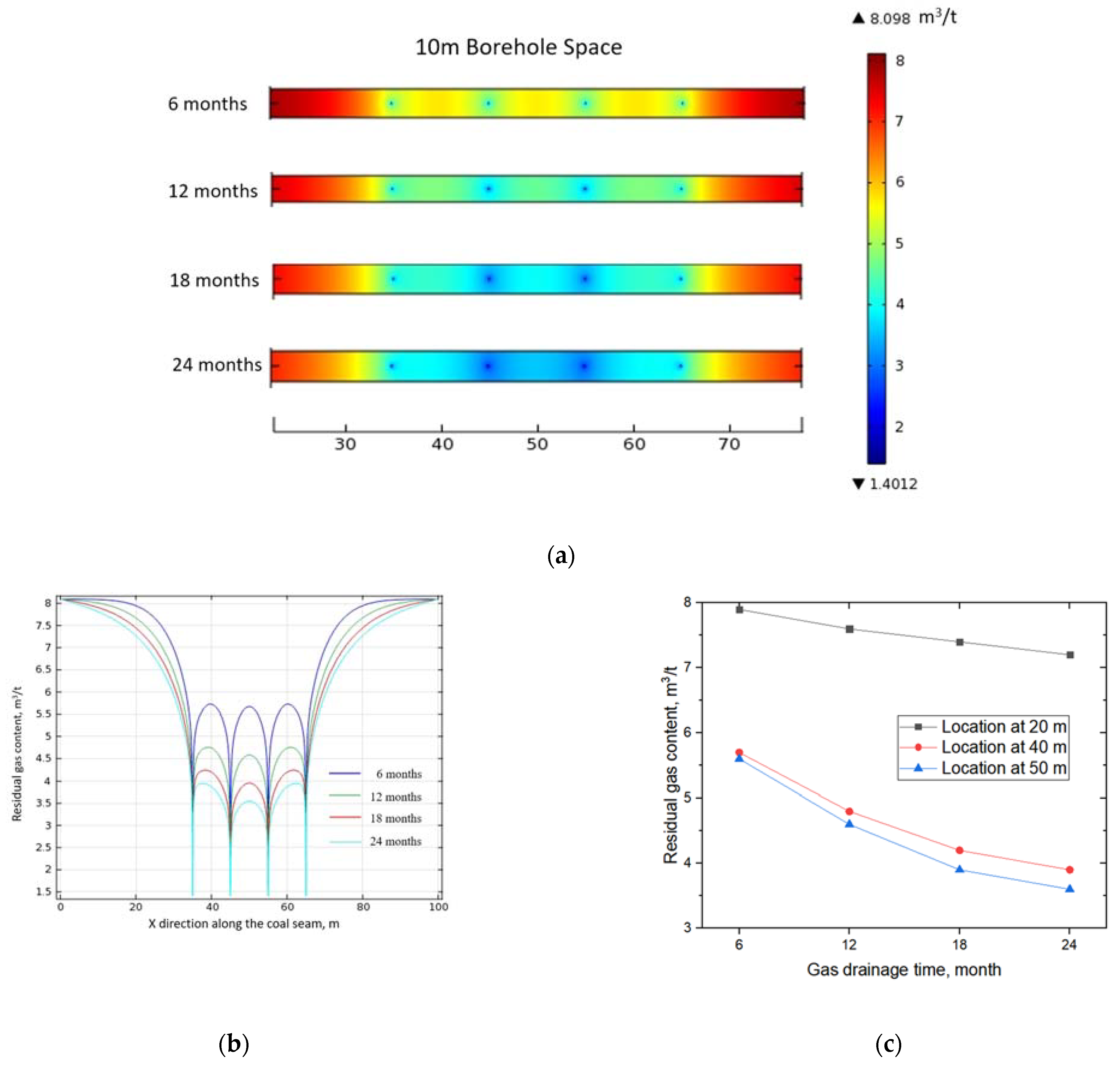
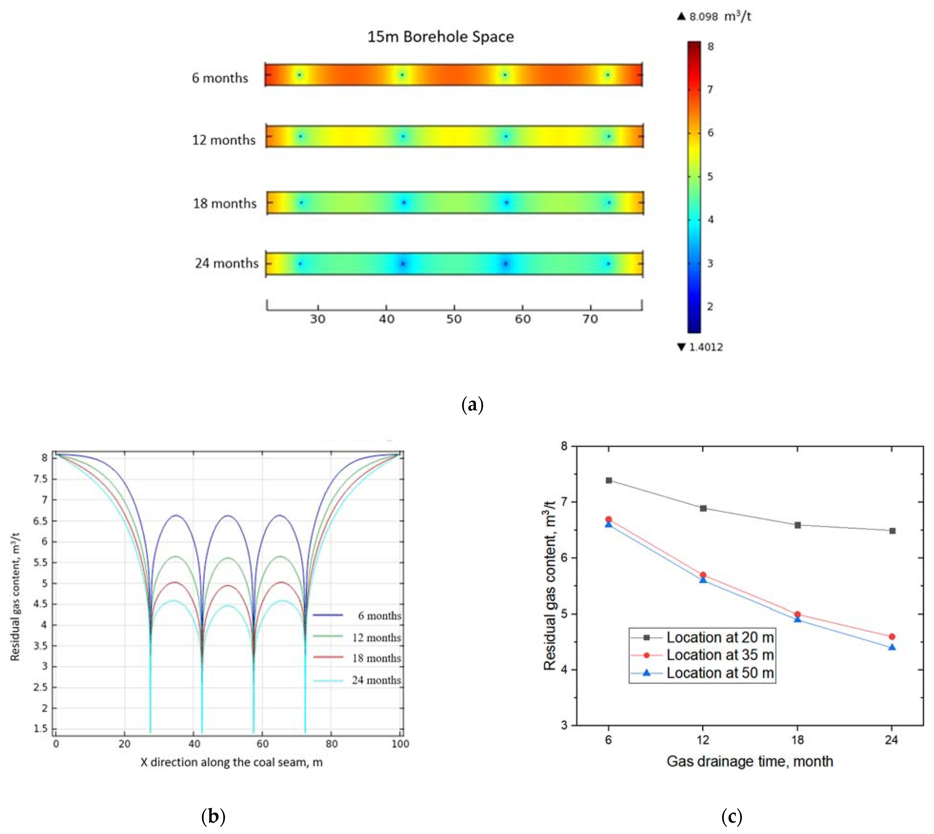
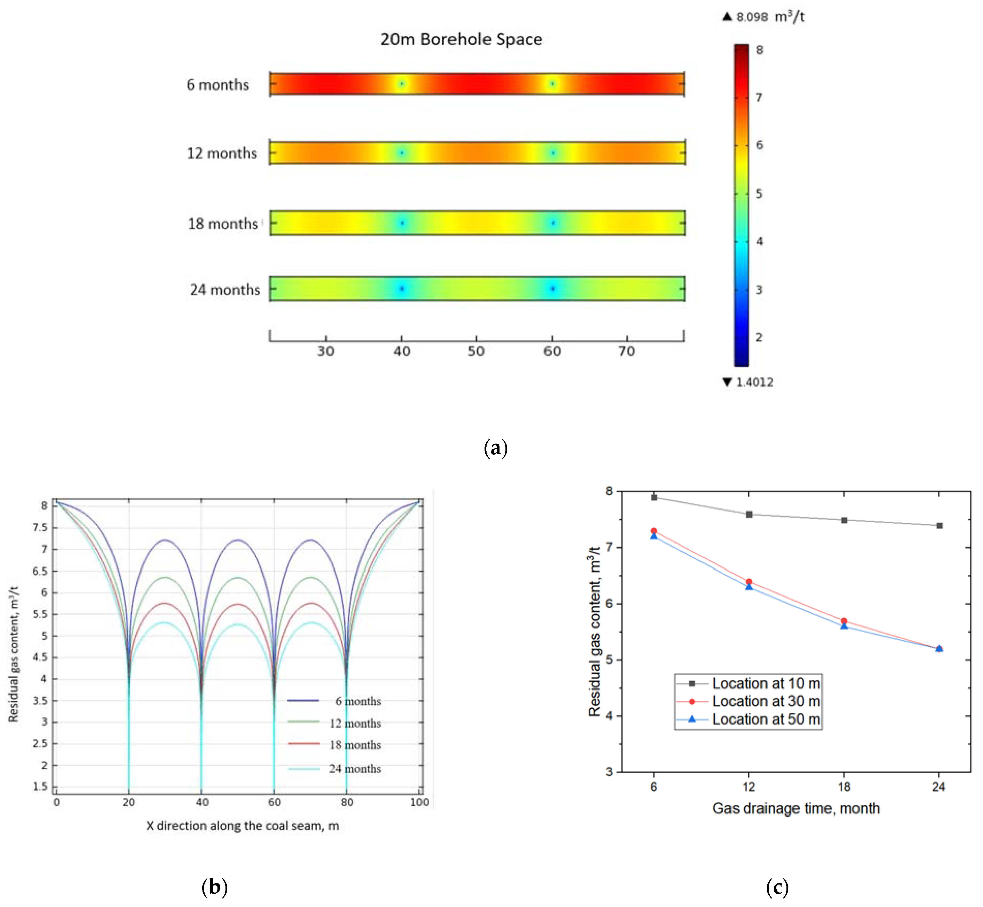
Both the directional borehole scenarios and the normal parallel borehole scenarios were simulated in this study. For the directional borehole simulations, four time periods were used—6 months, 12 months, 18 months, and 24 months. Figure 4, Figure 5 and Figure 6 show the simulation results of the different borehole sizes. For a better illustration, the gas content contour is between 25 m and 75 m of the total simulation geometry model. The diameter of the directional borehole was 113 mm. In order to quantify the gas drainage performance, a horizontal line is shown and the gas content variations are presented in the figures.
For all three scenarios (sizes of 10 m, 15 m, and 20 m), the gas drainage performance increased with the gas drainage time. The more time that was given for gas drainage, the lower the gas content was. For example, when the borehole size was 10 m, the maximum gas content was in the middle of two adjacent boreholes, and the gas content decreased from 5.7 m3/t to 4 m3/t.
For a better explanation, three points in the coal seam were chosen and the gas content variations are plotted in Figure 4. These three points represent different locations in the coal seam relative to the gas drainage boreholes. The point located at 20 m was only affected by the nearest borehole. From Figure 4, it can be seen that the gas content dropped from 7.9 m3/t to 7.2 m3/t. The gas drainage performance was not good. When 5 m3/t was set as the threshold limit value for the gas drainage, the 0–32 m coal seams (x-axis direction) did not meet the requirement. The point located at 40 m was in the middle of the two adjacent boreholes. From the gas content profiles, the gas content was the highest compared to the other points. If the gas content in this area met the gas drainage requirement, the gas content in other areas was also lower than the threshold limit value. From Figure 6, it can be seen that the gas content was much lower. The total gas content dropped from 5.6 m3/t to 3.6 m /t when the gas drainage time increased from 6 months to 24 months. Similar results were observed for the point located at 50 m. It should also be noted that the gas content dropped below the threshold limit value between 6 months and 12 months, which means that the gas drainage leading time should be less than 12 months if a 10 m borehole is used.
For the 15 m borehole and 20 m borehole simulations, the overall trends were similar to the 10 m borehole simulations. However, the residual gas content after the gas drainage was higher, which is in line with our expectations. When the borehole size was 15 m, the residual gas content dropped below the threshold limit value after 18 months of drainage. Table 5 summarizes the gas drainage performance for different drainage conditions. It can be concluded that both the gas drainage borehole size and the gas drainage leading time should be considered for the design of gas drainage boreholes. The smaller the used borehole size is, the higher the borehole drilling cost is. The more leading time there is given for gas drainage, the lower the residual gas content is.

3.5.2. Normal Parallel Borehole Simulations

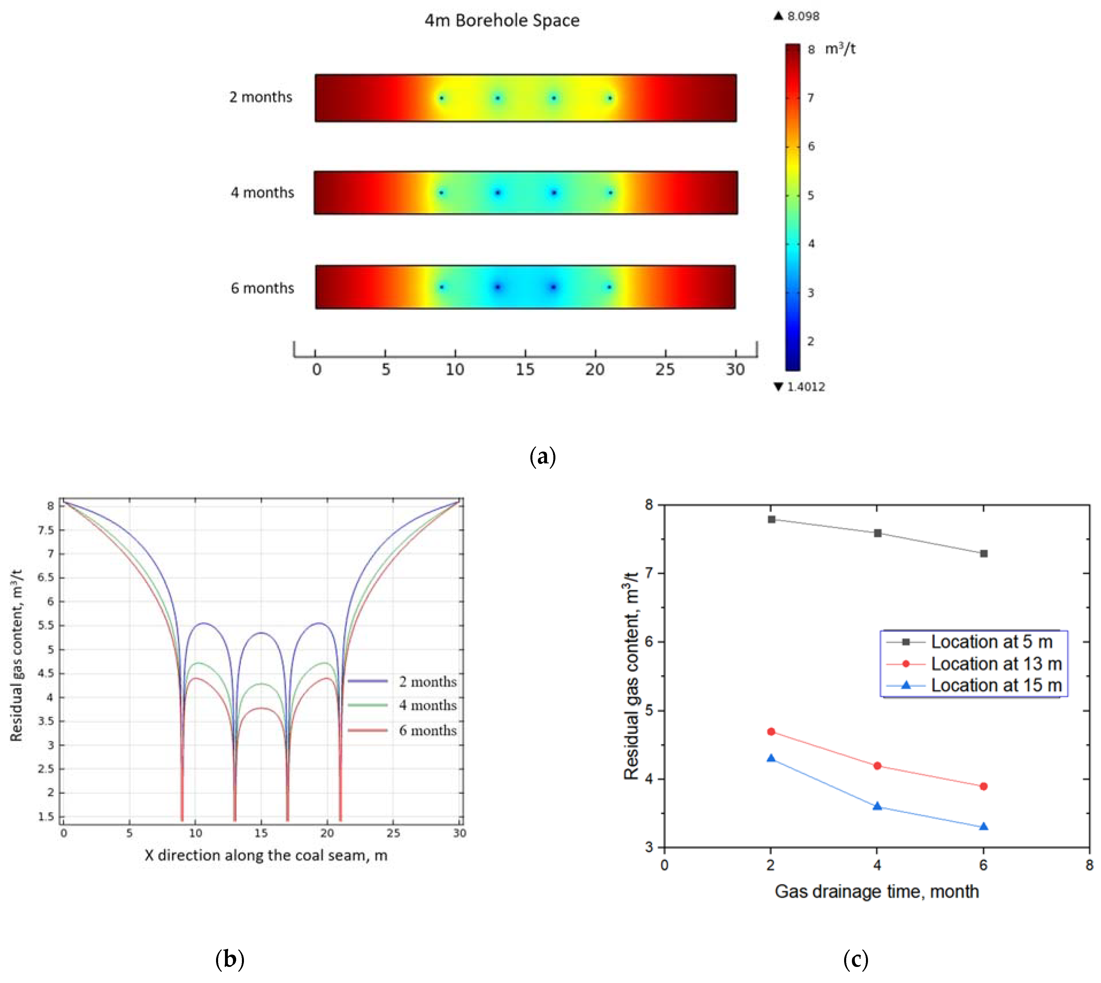
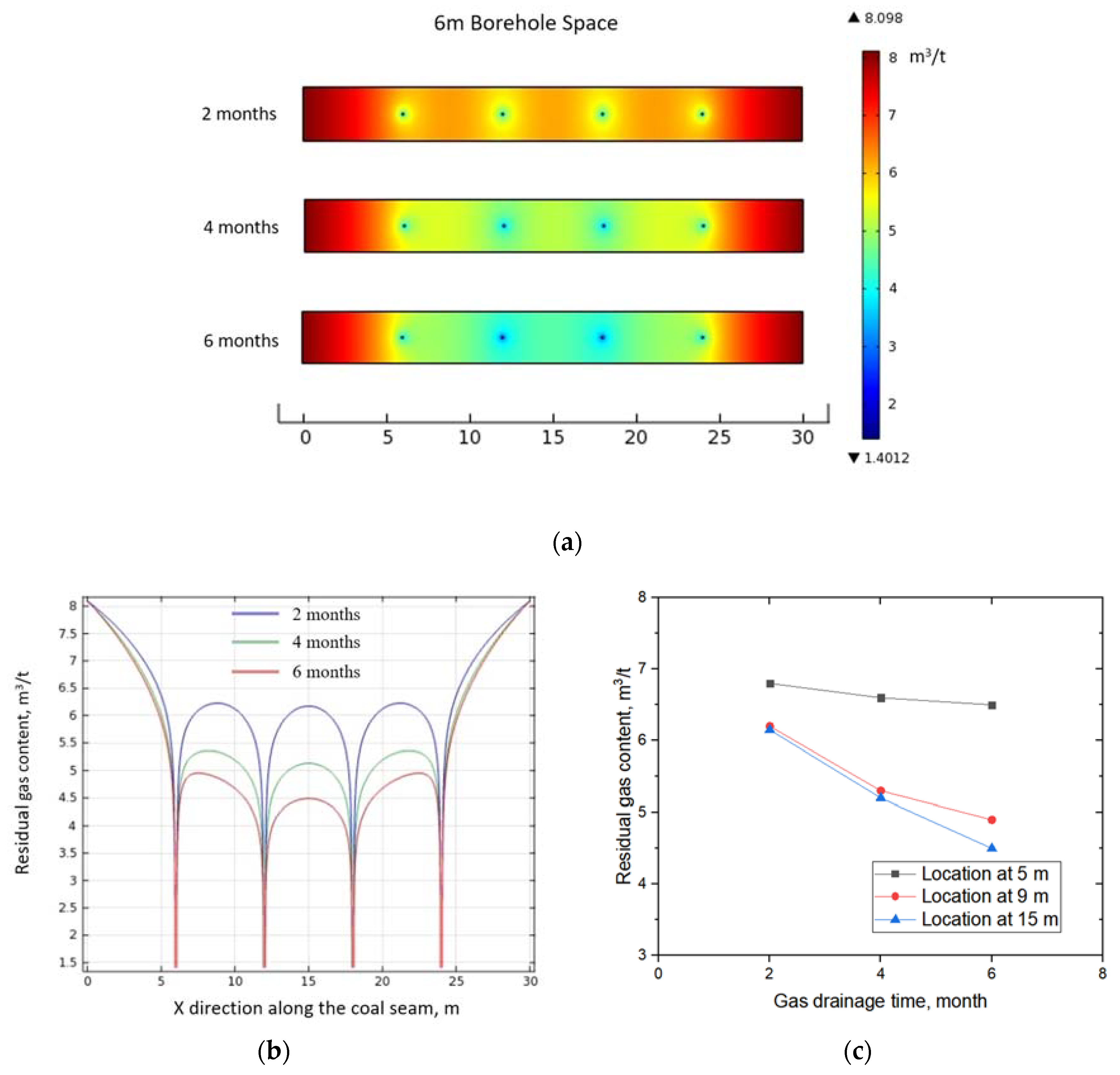
As shown in Figure 3, the length of the normal parallel borehole was much shorter than the directional borehole. It was drilled by a much lighter drilling rig that had more mobility. In this study, three different borehole sizes were used—2 m, 4 m, and 6 m. The gas drainage leading times were 2 months, 4 months, and 6 months. The parameters used for these simulations were the same as for the directional borehole simulations, except for the borehole diameter. Figure 7, Figure 8 and Figure 9 show the simulation results of different borehole sizes.
Similar results were observed from the simulation results for the normal parallel borehole scenarios. One significant difference was that the gas drainage time was much shorter due to the small borehole size. Table 6 summarizes the gas drainage results.
It should also be noted that the gas drainage effective area was quite dependent on the borehole size. In this area, four boreholes were drilled into the coal seam. A 30 m coal seam was built into the simulation model. The interference of the other borehole was significant. Specifically, the total gas drainage results are a combination of the four boreholes. The gas drainage targeted area was only the coal between the first borehole and the fourth borehole (from left to right), as summarized in Table 7. For example, in the 2 m borehole, after 2 months of gas drainage, the coal seam in the area of 11.5–18.5 m met the gas drainage requirement, and approximately 7 m of the coal seam was affected by the four gas drainage boreholes. With the increase in the gas drainage time, the affected coal seam increased slowly. Six months of drainage only affected 8 m of the coal seam, while the gas drainage was three times longer (2 m borehole scenario). With the increase in the borehole size, the gas drainage-affected areas significantly rose. With six months of drainage, the affected coal seam was 19.2 m in length (6 m borehole scenario). It can be concluded that the gas drainage process targeted the coal seams between the two adjacent boreholes. With the increase in the gas drainage time, the gas drained out from this targeted area rather than expanding to the affected area. The smaller the affected area is, the more gas drainage boreholes should be drilled, which means a higher cost. For field applications, both the time and cost should be considered during the borehole design process.

4. Field Observations and Discussions

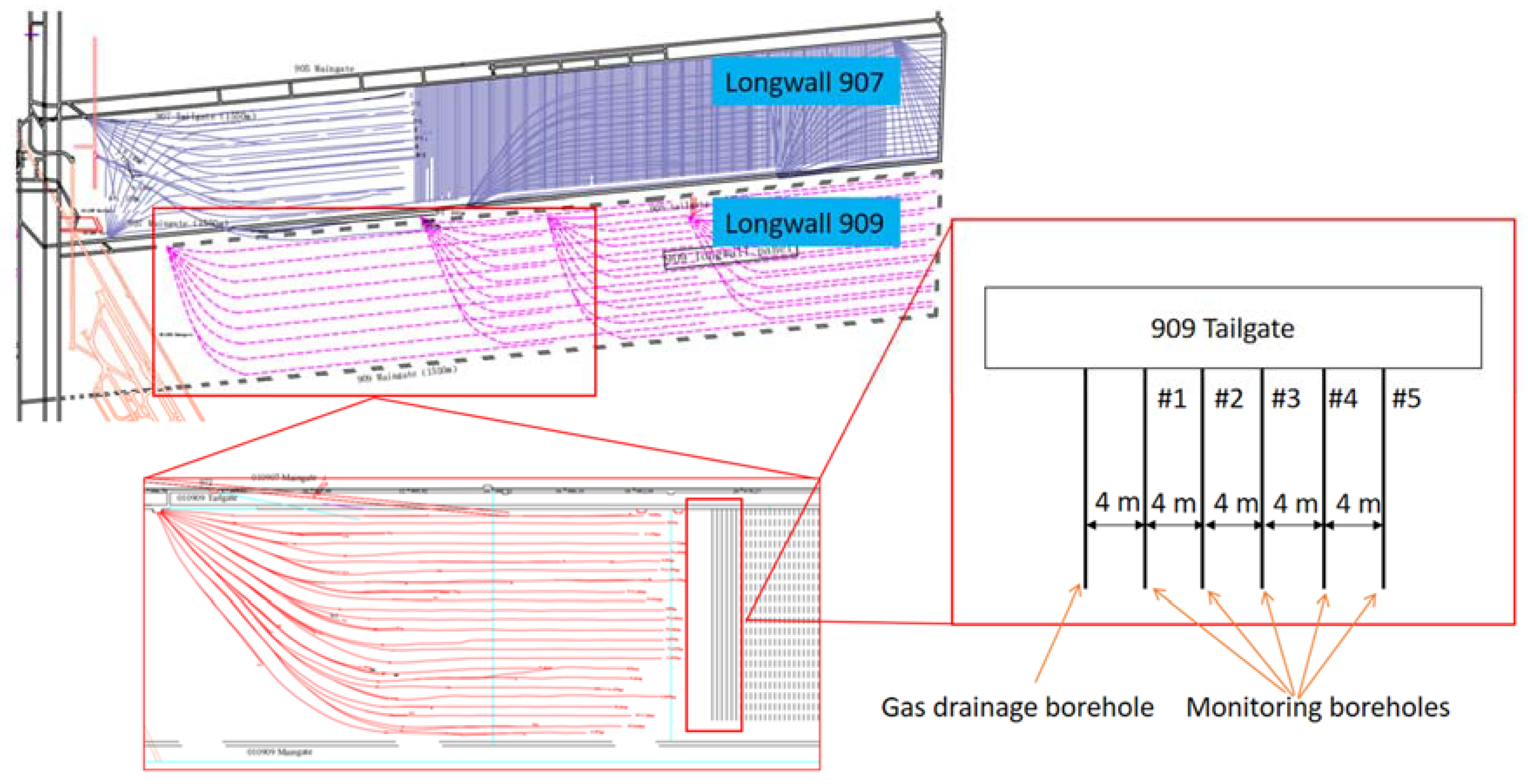
Field observations were carried out in Longwall Panel 909 in the Wuhushan coal mine. Currently, this longwall panel is under preparations, and gas drainage work is being done. One set of parallel boreholes were drilled. The layout of the boreholes is shown in Figure 10. In order to check the gas drainage performance, one parallel in-seam borehole was used as the gas drainage borehole, and five monitoring boreholes were used to monitor the gas pressure variations. In this study, the gas pressure drop method was used to evaluate the gas drainage performance. Specifically, one borehole (drainage borehole) was undergoing normal gas drainage work and the other five boreholes (monitoring boreholes) were sealed after borehole drilling. The borehole size was set as 4 m. For the five monitoring boreholes, cement sealing with a length of 20 m was used for each borehole. A pressure gauge was installed to record the gas pressure in the borehole. The gas pressures were recorded every day for six months.
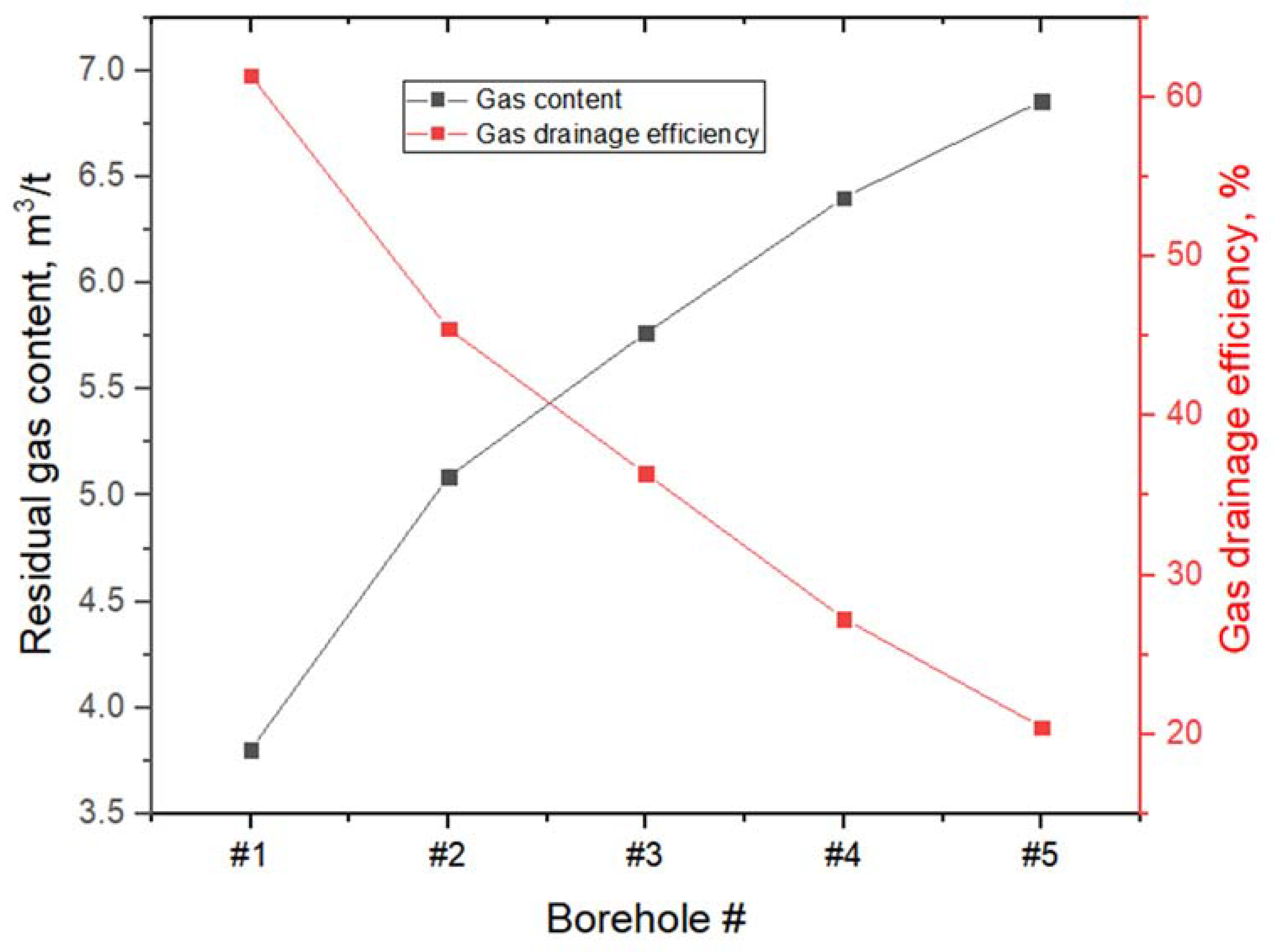
For the real conditions, we could not measure the gas contents for different gas drainage times (if we measured the gas content, we collected the cores of the borehole and measured the gas volume, and only one reading could be obtained). Thus, we used a pressure gauge to monitor the gas pressures with respect to the gas drainage time (gas pressure drop method), as shown in Figure 11. The gas pressures variations are shown with respect to the period of 180 days. All five boreholes show a decreasing trend with the increase in monitoring time, which means that the gas drainage borehole influenced the monitoring area. The gas drainage effects dropped with the increase in distance (between the monitoring borehole and the drainage borehole). Specifically, Borehole 1 had the largest drop in pressure, and at the end of the monitoring, the gas pressure was 0.18 MPa. The gas content was 3.8 m3/t (the Langmuir model was used to back analyze the gas content.), and 61.36% of the total gas was recovered.
Figure 12 shows the gas drainage results after 180 days of drainage. The gas drainage efficiency was calculated by the following:
e = V t V r V t
where e is the gas drainage efficiency, V t is the total gas content or the initial gas content at the beginning of monitoring, V r is the residual gas content or the final gas content at the end of monitoring. When 5 m3/t was taken as the threshold limit value, the residual gas content of Borehole 2 was 5.05 m3/t. This means that after 6 months of drainage, the gas drainage borehole affected less than 8 m (the space between the gas drainage borehole and monitored Borehole 2 was 8 m). This finding is in accordance with our previous simulation results.
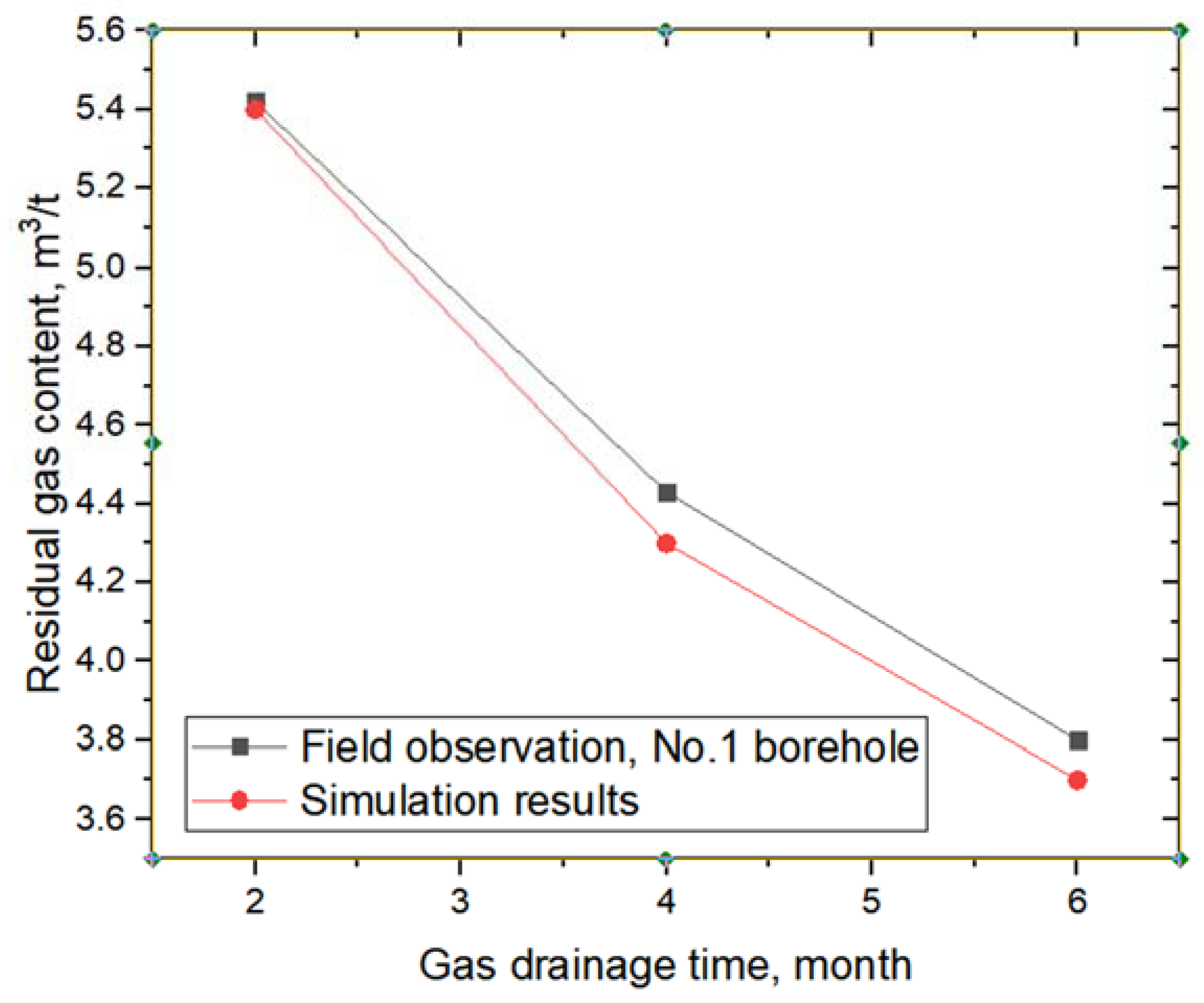
From the final results, we can see that after 6 months of gas drainage, only the first borehole (Borehole 1), met the gas drainage performance requirements (the gas content was below 5 m3/t). In the simulations, the gas content variations of the whole coal seam could be obtained. In the field observations, we could only use one point at different gas drainage times for evaluations. Here, the gas contents at 15 m in the X-axial direction (simulation results) were compared with the field observations, as shown in Figure 13. Because an ideal no gas flow condition was applied to the simulations within the boundary, the gas content does not precisely represent the real conditions. For the underground coal seam, the excavations of the roadways significantly affected the gas emissions, so that the gas content decreased even though there were no gas drainage boreholes (even though the borehole sealing length was 20 m, the gas emission effects were still obvious.). From the comparison, it can be seen that the simulation results correspond well with the field observations. For example, the maximum difference in residual gas content between the simulations and field observations was 0.13 m3/t, after 6 months of drainage. It can be concluded that this model is effective and reliable.
It should be noted that there was a negative correlation between the borehole density and the borehole size. A large borehole means the density of the borehole is lower and fewer boreholes are drilled, lowering the cost of borehole drilling. As was observed in the simulations and field observations, the gas drainage results were highly affected by the borehole size. With the increase in gas drainage leading times, the residual gas content dropped. In field productions, balance should be achieved between the gas drainage time and the borehole size. Usually, the gas drainage work is carried out in the next longwall panel. Enough time should be allotted for the gas drainage work. From this study, we found that the gas drainage effective area is mostly located in the coal seam between two adjacent boreholes, which is illustrated in the contour figures in Section 3.5. The gas drainage efficiency is much higher in the targeted coal seam (between two adjacent boreholes). For a small borehole size, the residual gas content drops quickly below the threshold limit value. With the increase in drainage time, more gas is drained from the targeted coal seam, rather than from other areas. In this study, this was clearly observed. For the 2 m borehole test, the gas drainage targeted area was 8 m (four gas drainage boreholes), while for the 8 m borehole test, the gas drainage targeted area was 19.2 m. In the field production, large borehole sizes should be considered, along with the gas drainage time.

5. Future Studies for CO2 Geo-Sequestration in Coal Seams

In this study, we only performed gas recovery; CO2 geo-sequestration is the opposite directional movement of gas migration (gas recovery is gas draining out of a coal seam; CO2 geo-sequestration is gas draining into a coal seam). There are many common points between these two processes but the differences should not be ignored. For example, the gas types are different and the total project durations are different. We recommend that further studies be conducted in the future. CO2 geo-sequestration in coal seams is opposite to the gas drainage process, but the gas migration mechanisms are similar. The fracture system is the main flow channel and the micropores are the main storage sites [32,43]. In this study, it was proved that the borehole size is critical for gas migration. For the CO2 geo-sequestration process, the injected CO2 accumulates near the injection well. For horizontal wells, it also exists near the horizontal well. With the increase in the duration of gas injection, the accumulated CO2 would migrate further into the coal seams. It should also be noted that the permeability used in this study was relatively high. With the increase in the depth of cover, the coal seam permeability dropped sharply. For a low permeable seam, the gas migration patterns differed from the high ones; it would take a much longer time for the gas to migrate. One of the key issues for CO2 geo-sequestration in underground coal seams is the permeability reduction effect. Due to the high adsorption capacity of coal to CO2, the sorption-induced permeability reduction is significant during the CO2 injection process. In previous studies, it was found that the permeability was one or two orders of magnitude lower than the initial permeability in the later period of injection. As a result, most of the CO2 accumulated near the injection boreholes. It is essential to be familiar with the gas migration patterns. This study can provide suggestions for CO2 geo-sequestration. From the field observations and simulations, the gas migrations patterns were determined under these specific geological conditions. For the CO2 geo-sequestration process, the integrations of gas injection pressure, borehole size, and permeability can be studied. All these findings are useful and can contribute to field studies of CO2 geo-sequestration. In this study, the gas migration patterns near the borehole were clear for different time periods. Meanwhile, for different borehole sizes, the gas flowability in the coal seams was determined. We found the relationship between the parameters and the gas concentrations. In future studies, for the CO2 injection times and CO2 injection well design, this study can be referred to. Meanwhile, attention should be paid to the permeability reduction effects [44,45]. The adsorption capacity of coal to CO2 is 2–5 times higher than that of coal to methane [46,47]. CO2 injection wells should be designed properly for long-term injections. Numerical simulations would be one effective method to calculate the total boreholes or injection wells.

6. Conclusions

A numerical model was proposed and different borehole size scenarios were simulated for both directional boreholes and normal parallel boreholes. Based on the simulation results, six boreholes were drilled into an underground longwall panel. After six months of drainage, the gas drainage effective area was defined and the gas migration patterns near the gas drainage boreholes were determined.
The numerical model incorporates the coal physical structure and the gas seepage mechanism. The solid-fluid coupled model can be used to predict the gas migration patterns in coal seams. This model is useful for field applications of borehole designs.
Gas drainage performance is tightly affected by the borehole size and the gas drainage time. Under the same gas drainage time conditions, with the increase in borehole size, the residual coal seam gas was higher and the gas drainage results were less effective. With the increase in the gas drainage time, the residual gas content dropped. Specifically, for the directional boreholes (size of 10 m, 15 m, and 20 m), it would take 12 months, 18 months, and 24 months to reduce the gas content below the threshold limit value, respectively. For the normal parallel boreholes (sizes of 2 m, 4 m, and 6 m), it would take 2 months, 4 months, and 6 months to reduce the gas content below the threshold limit value, respectively.
Six boreholes 4 m in size, were drilled. Drops in gas pressure were observed for all five monitoring boreholes. Borehole 1 had the highest pressure, and 61.36% of the total gas was recovered. After 6 months of drainage, only Boreholes 1 and 2 met the gas drainage requirements. The effective gas drainage diameter was smaller than 8 m, which is in line with the simulation results.

Author Contributions

Conceptualization, H.L. and Z.S.; methodology, X.X. and J.L.; validation, H.L., Y.S. and X.W.; formal analysis, J.L.; writing—original draft preparation, Z.S.; writing—review and editing, J.L.; supervision, H.L.; project administration, X.W.; funding acquisition, H.L. All authors have read and agreed to the published version of the manuscript.

Funding

This research was funded by the China Postdoctoral Science Foundation, grant number 2021M693407.

Data Availability Statement

Data sharing is not applicable.

Acknowledgments

Field support from the Wuhushan coal mine are acknowledged.

Conflicts of Interest

The authors declare no conflict of interest.

References

  1. Hamawand, I.; Yusaf, T.; Hamawand, S.G. Coal seam gas and associated water: A review paper. Renew. Sustain. Energy Rev. 2013, 22, 550–560. [Google Scholar] [CrossRef]
  2. Fleming, D.A.; Measham, T.G. Local economic impacts of an unconventional energy boom: The coal seam gas industry in Australia. Aust. J. Agric. Resour. Econ. 2015, 59, 78–94. [Google Scholar] [CrossRef] [Green Version]
  3. Yang, W.; Lu, C.; Si, G.; Lin, B.; Jiao, X. Coal and gas outburst control using uniform hydraulic fracturing by destress blasting and water-driven gas release. J. Nat. Gas Sci. Eng. 2020, 79, 103360. [Google Scholar] [CrossRef]
  4. Fan, C.; Li, S.; Luo, M.; Du, W.; Yang, Z. Coal and gas outburst dynamic system. Int. J. Min. Sci. Technol. 2017, 27, 49–55. [Google Scholar] [CrossRef]
  5. Zhang, G.; Ranjith, P.G.; Wu, B.; Perera, M.S.A.; Haque, A.; Li, D. Synchrotron X-ray tomographic characterization of microstructural evolution in coal due to supercritical CO2 injection at in-situ conditions. Fuel 2019, 255, 115696. [Google Scholar] [CrossRef]
  6. Zhang, G.; Ranjith, P.G.; Fu, X.; Li, X. Pore-fracture alteration of different rank coals: Implications for CO2 sequestration in coal. Fuel 2021, 289, 119801. [Google Scholar] [CrossRef]
  7. Si, G.; Durucan, S.; Jamnikar, S.; Lazar, J.; Abraham, K.; Korre, A.; Shi, J.-Q.; Zavšek, S.; Mutke, G.; Lurka, A. Seismic monitoring and analysis of excessive gas emissions in heterogeneous coal seams. Int. J. Coal Geol. 2015, 149, 41–54. [Google Scholar] [CrossRef]
  8. Salmachi, A.; Rajabi, M.; Wainman, C.; Mackie, S.; McCabe, P.; Camac, B.; Clarkson, C. History, Geology, In Situ Stress Pattern, Gas Content and Permeability of Coal Seam Gas Basins in Australia: A Review. Energies 2021, 14, 2651. [Google Scholar] [CrossRef]
  9. Viney, N.R.; Post, D.A.; Crosbie, R.S.; Peeters, L.J.M. Modelling the impacts of future coal mining and coal seam gas extraction on river flows: A methodological framework. J. Hydrol. 2021, 596, 126–144. [Google Scholar] [CrossRef]
  10. Zhang, Q.; Zheng, J.; Zhang, B.; Linga, P. Coal mine gas separation of methane via clathrate hydrate process aided by tetrahydrofuran and amino acids. Appl. Energy 2021, 287, 116576. [Google Scholar] [CrossRef]
  11. Zhao, P.; Zhuo, R.; Li, S.; Lin, H.; Shu, C.-M.; Laiwang, B.; Jia, Y.; Suo, L. Fractal characteristics of gas migration channels at different mining heights. Fuel 2020, 271, 117479. [Google Scholar] [CrossRef]
  12. Zhao, P.; Liu, H.; Ho, C.-H.; Li, S.; Liu, Y.; Lin, H.; Yan, M. Evaluating Methane Adsorption Characteristics of Coal-Like. Materials 2020, 13, 751. [Google Scholar] [CrossRef] [PubMed] [Green Version]
  13. Zhao, P.; Zhuo, R.; Li, S.; Shu, C.-M.; Jia, Y.; Lin, H.; Chang, Z.; Ho, C.-H.; Laiwang, B.; Xiao, P. Fractal characteristics of methane migration channels in inclined coal seams. Energy 2021, 225, 120127. [Google Scholar] [CrossRef]
  14. Qin, L.; Wang, P.; Li, S.; Lin, H.; Wang, R.; Wang, P.; Ma, C. Gas adsorption capacity changes in coals of different ranks after liquid nitrogen freezing. Fuel 2021, 292, 120404. [Google Scholar] [CrossRef]
  15. Xie, W.; Wang, M.; Duan, H. Adsorption Characteristics and Controlling Factors of CH4 on Coal-Measure Shale, Hedong Coalfield. Minerals 2021, 11, 63. [Google Scholar] [CrossRef]
  16. Keles, C.; Tang, X.; Schlosser, C.; Louk, A.K.; Ripepi, N.S. Sensitivity and history match analysis of a carbon dioxide “huff-and-puff” injection test in a horizontal shale gas well in Tennessee. J. Nat. Gas Sci. Eng. 2020, 77, 103226. [Google Scholar] [CrossRef]
  17. Zhang, Z.; Liu, G.; Cao, Y.; Lin, J.; Jin, Y.; Xian, B.; Lv, R.; Zhang, Z. Experimental Investigation of CS2 Extraction to Enhance the Permeability of Coal. Transp. Porous Media 2021, 136, 899–922. [Google Scholar] [CrossRef]
  18. Zhang, C.; Wang, F.; Bai, Q. Underground space utilization of coalmines in China: A review of underground water reservoir construction. Tunn. Undergr. Space Technol. 2021, 107, 103657. [Google Scholar] [CrossRef]
  19. Cao, W.; Shi, J.-Q.; Durucan, S.; Si, G.; Korre, A. Gas-driven rapid fracture propagation under unloading conditions in coal and gas outbursts. Int. J. Rock Mech. Min. Sci. 2020, 130, 104325. [Google Scholar] [CrossRef]
  20. Lin, J.; Ren, T.; Wang, G.; Nemcik, J. Simulation investigation of N2-injection enhanced gas drainage: Model development and identification of critical parameters. J. Nat. Gas Sci. Eng. 2018, 55, 30–41. [Google Scholar] [CrossRef]
  21. Huo, B.; Jing, X.; Fan, C.; Han, Y. Numerical investigation of flue gas injection enhanced underground coal seam gas drainage. Energy Sci. Eng. 2019, 7, 3204–3219. [Google Scholar] [CrossRef]
  22. Dong, J.; Cheng, Y.; Pan, Z. Comparison of transient and pseudo-steady diffusion of methane in coal and implications for coalbed methane control. J. Pet. Sci. Eng. 2020, 184, 106543. [Google Scholar] [CrossRef]
  23. Xia, T.; Zhou, F.; Gao, F.; Kang, J.; Liu, J.; Wang, J. Simulation of coal self-heating processes in underground methane-rich coal seams. Int. J. Coal Geol. 2015, 141–142, 1–12. [Google Scholar] [CrossRef]
  24. Zhang, Y.; Underschultz, J.; Langhi, L.; Mallants, D.; Strand, J. Numerical modelling of coal seam depressurization during coal seam gas production and its effect on the geomechanical stability of faults and coal beds. Int. J. Coal Geol. 2018, 195, 1–13. [Google Scholar] [CrossRef] [Green Version]
  25. Zhang, C.; Yu, L.; Feng, R.; Zhang, Y.; Zhang, G. A Numerical Study of Stress Distribution and Fracture Development above a Protective Coal Seam in Longwall Mining. Processes 2018, 6, 146. [Google Scholar] [CrossRef] [Green Version]
  26. Lin, J.; Ren, T.; Cheng, Y.; Nemcik, J.; Wang, G. Cyclic N2 injection for enhanced coal seam gas recovery: A laboratory study. Energy 2019, 188, 116115. [Google Scholar] [CrossRef]
  27. Lin, J.; Ren, T.; Wang, G.; Booth, P.; Nemcik, J. Experimental investigation of N2 injection to enhance gas drainage in CO2-rich low permeable seam. Fuel 2018, 215, 665–674. [Google Scholar] [CrossRef]
  28. Bai, G.; Su, J.; Zhang, Z.; Lan, A.; Zhou, X.; Gao, F.; Zhou, J. Effect of CO2 injection on CH4 desorption rate in poor permeability coal seams: An experimental study. Energy 2022, 238, 121674. [Google Scholar] [CrossRef]
  29. Awan, F.U.R.; Keshavarz, A.; Akhondzadeh, H.; Al-Anssari, S.; Al-Yaseri, A.; Nosrati, A.; Ali, M.; Iglauer, S. Stable Dispersion of Coal Fines during Hydraulic Fracturing Flowback in Coal Seam Gas Reservoirs—An Experimental Study. Energy Fuels 2020, 34, 5566–5577. [Google Scholar] [CrossRef]
  30. Sampath, K.H.S.M.; Perera, M.S.A.; Elsworth, D.; Ranjith, P.G.; Matthai, S.K.; Rathnaweera, T.; Zhang, G. Effect of coal maturity on CO2-based hydraulic fracturing process in coal seam gas reservoirs. Fuel 2019, 236, 179–189. [Google Scholar] [CrossRef]
  31. Zhao, P.; Liu, H.; Li, S.; Lin, H.; Jia, Y.; Yan, M.; Yuan, M.; Lin, J. Experimental Investigation of the Adsorption Characteristics of Mixed Coal and Variations of Specific Surface Areas before and after CH4 Adsorption. Appl. Sci. 2019, 9, 524. [Google Scholar] [CrossRef] [Green Version]
  32. Saghafi, A. Potential for ECBM and CO2 storage in mixed gas Australian coals. Int. J. Coal Geol. 2010, 82, 240–251. [Google Scholar] [CrossRef]
  33. Suchowerska, A.M.; Merifield, R.S.; Carter, J.P. Vertical stress changes in multi-seam mining under supercritical longwall panels. Int. J. Rock Mech. Min. Sci. 2013, 61, 306–320. [Google Scholar] [CrossRef]
  34. Du, F.; Wang, K. Unstable failure of gas-bearing coal-rock combination bodies: Insights from physical experiments and numerical simulations. Process Saf. Environ. Prot. 2019, 129, 264–279. [Google Scholar] [CrossRef]
  35. Kiyama, T.; Nishimoto, S.; Fujioka, M.; Xue, Z.; Ishijima, Y.; Pan, Z.; Connell, L.D. Coal swelling strain and permeability change with injecting liquid/supercritical CO2 and N2 at stress-constrained conditions. Int. J. Coal Geol. 2011, 85, 56–64. [Google Scholar] [CrossRef]
  36. Sarda, S.; Jeannin, L.; Bourbiaux, B. Hydraulic characterization of fractured reservoirs: Simulation on discrete fracture models. In Proceedings of the SPE Reservoir Simulation Symposium, Houston, TX, USA, 11–14 February 2001. [Google Scholar]
  37. Fan, C.; Elsworth, D.; Li, S.; Zhou, L.; Yang, Z.; Song, Y. Thermo-hydro-mechanical-chemical couplings controlling CH4 production and CO2 sequestration in enhanced coalbed methane recovery. Energy 2019, 173, 1054–1077. [Google Scholar] [CrossRef]
  38. Fan, C.; Li, S.; Elsworth, D.; Han, J.; Yang, Z. Experimental investigation on dynamic strength and energy dissipation characteristics of gas outburst—Prone coal. Energy Sci. Eng. 2020, 8, 1015–1028. [Google Scholar] [CrossRef]
  39. Birkedal, K.A.; Hauge, L.P.; Graue, A.; Ersland, G. Transport mechanisms for CO2-CH4 exchange and safe CO2 storage in hydrate-bearing sandstone. Energies 2015, 8, 4073–4095. [Google Scholar] [CrossRef] [Green Version]
  40. Tambach, T.J.; Mathews, J.P.; van Bergen, F. Molecular Exchange of CH4 and CO2 in Coal: Enhanced Coalbed Methane on a Nanoscale. Energy Fuels 2009, 23, 4845–4847. [Google Scholar] [CrossRef]
  41. Liu, Q.; Chu, P.; Zhu, J.; Cheng, Y.; Wang, D.; Lu, Y.; Liu, Y.; Xia, L.; Wang, L. Numerical assessment of the critical factors in determining coal seam permeability based on the field data. J. Nat. Gas Sci. Eng. 2020, 74, 103098. [Google Scholar] [CrossRef]
  42. Yang, X.; Wang, G.; Du, F.; Jin, L.; Gong, H. N2 injection to enhance coal seam gas drainage (N2-ECGD): Insights from underground field trial investigation. Energy 2022, 239, 122247. [Google Scholar] [CrossRef]
  43. Saghafi, A.; Faiz, M.; Roberts, D. CO2 storage and gas diffusivity properties of coals from Sydney Basin, Australia. Int. J. Coal Geol. 2007, 70, 240–254. [Google Scholar] [CrossRef]
  44. Guo, H.; Ni, X.; Wang, Y.; Du, X.; Yu, T.; Feng, R. Experimental Study of CO2-Water-Mineral Interactions and Their Influence on the Permeability of Coking Coal and Implications for CO2-ECBM. Minerals 2018, 8, 117. [Google Scholar] [CrossRef] [Green Version]
  45. Lin, J.; Ren, T.; Cheng, Y.; Nemcik, J. Laboratory quantification of coal permeability reduction effect during carbon dioxide injection process. Process Saf. Environ. Prot. 2021, 148, 638–649. [Google Scholar] [CrossRef]
  46. Sander, R.; Connell, L.D.; Camilleri, M.; Pan, Z. CH4, CO2, N2 diffusion in Bowen Basin (Australia) coal: Relationship between sorption kinetics of coal core and crushed coal particles. J. Nat. Gas Sci. Eng. 2020, 81, 103468. [Google Scholar] [CrossRef]
  47. Sander, R.; Connell, L.D.; Pan, Z.; Camilleri, M.; Heryanto, D.; Lupton, N. Core flooding experiments of CO2 enhanced coalbed methane recovery. Int. J. Coal Geol. 2014, 131, 113–125. [Google Scholar] [CrossRef]
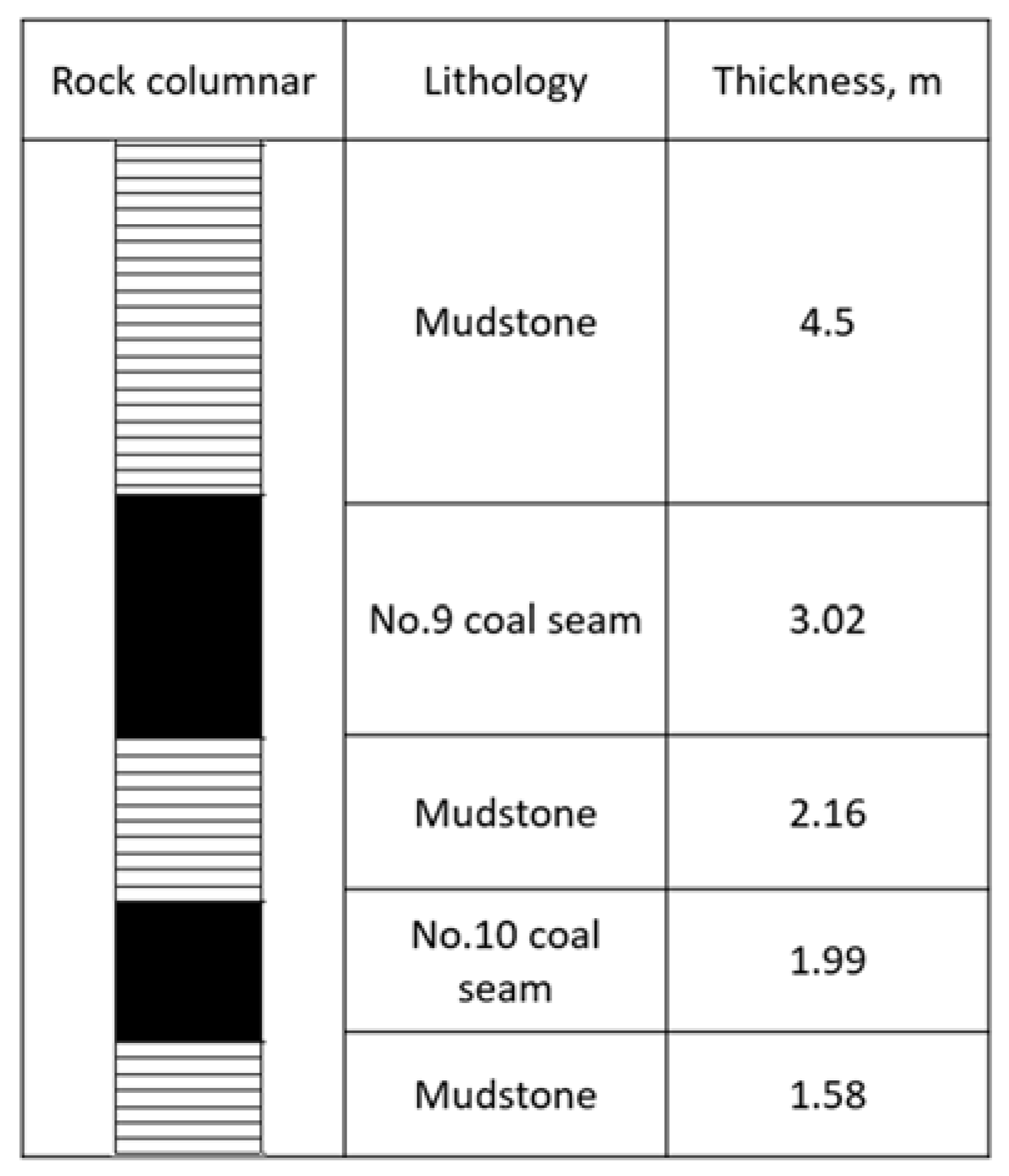
Figure 1. Rock columnar near the No. 9 and No. 10 coal seams in the Wuhushan coal mine.
Minerals 11 01254 g001
Figure 2. Gas drainage boreholes—directional borehole and normal parallel borehole.
Minerals 11 01254 g002
Figure 3. Schematic diagram of the geometric model for simulations.
Minerals 11 01254 g003
Figure 4. Simulation results for the 10 m borehole. (a) Gas content contour; (b) residual gas content with respect to X direction along the coal seam; (c) gas content at three points with respect to gas drainage time.
Minerals 11 01254 g004
Figure 5. Simulation results for the 15 m borehole. (a) Gas content contour; (b) residual gas content with respect to X direction along the coal seam; (c) gas content at three points with respect to gas drainage time.
Minerals 11 01254 g005
Figure 6. Simulation results for the 20 m borehole. (a) Gas content contour; (b) residual gas content with respect to X direction along the coal seam; (c) gas content at three points with respect to gas drainage time.
Minerals 11 01254 g006
Figure 7. Simulation results of 2 m borehole. (a) Gas content contour; (b) residual gas content with respect to X direction along the coal seam; (c) gas content at three points with respect to gas drainage time.
Minerals 11 01254 g007
Figure 8. Simulation results of 4 m borehole. (a) Gas content contour; (b) residual gas content with respect to X direction along the coal seam; (c) gas content at three points with respect to gas drainage time.
Minerals 11 01254 g008
Figure 9. Simulation results of the 6 m borehole. (a) Gas content contour; (b) residual gas content with respect to X direction along the coal seam; (c) gas content at three points with respect to gas drainage time.
Minerals 11 01254 g009
Figure 10. Gas boreholes for field observations.
Minerals 11 01254 g010
Figure 11. Variations of gas pressures in five monitoring boreholes.
Minerals 11 01254 g011
Figure 12. Residual gas content and gas drainage efficiency after 180 days of drainage.
Minerals 11 01254 g012
Figure 13. Comparison between field observations and simulation results (4 m borehole size).
Minerals 11 01254 g013
Table 1. Proximate analysis of coal samples from No. 9 coal seam, Wuhushan coal mine.
LocationLangmuir Adsorption ConstantMoisture
Mad (%)
Ash
Ad (%)
Volatile Matter
Vdaf (%)
Fixed Carbon (%)Density (t/m3)Porosity
(%)
VL (m3/t)PL (MPa)
Excavation heading No. 906 roadway28.411.110.3510.1526.4563.051.343.6
Table 2. Coal samples for gas content measurements.
Sample No.LocationCoal Seam Thickness, mDepth of Cover, mTotal Gas Content, m3/t
1No. 906 roadway, Borehole 12.91209.207.90
2No. 906 roadway, Borehole 22.91207.507.78
3No. 905 return airway, Borehole 12.87207.807.89
4No. 905 return airway, Borehole 22.81208.008.06
5No. 905 return airway, Borehole 33.02201.207.34
6Main return airway of No. 9 coal seam, Borehole 12.97201.207.45
7Main return airway of No. 9 coal seam, Borehole 22.89201.007.82
8Main return airway of No. 9 coal seam, Borehole 32.88200.987.76
9Excavation heading No. 907 roadway, Borehole 13.03201.307.93
10Excavation heading No. 907 roadway, Borehole 23.01201.308.10
11Excavation heading No. 907 roadway, Borehole 33.16202.087.50
12Maingate of No. 9 coal seam, Borehole 13.15202.087.60
13Maingate of No. 9 coal seam, Borehole 23.30203.107.78
14Maingate of No. 9 coal seam, Borehole 33.30203.107.95
15No. 904 return airway, Borehole 12.91209.107.89
16No. 904 return airway, Borehole 22.90207.507.76
17No. 904 return airway, Borehole 32.86207.807.88
18No. 903 return airway, Borehole 13.08200.207.94
19No. 903 return airway, Borehole 22.83208.008.04
20No. 903 return airway, Borehole 32.86201.208.12
21No. 902 return airway, Borehole 12.90207.808.02
22No. 902 return airway, Borehole 22.86203.808.05
23No. 902 return airway, Borehole 33.08205.308.22
24No. 901 return airway3.08210.008.78
Table 3. Simulation scenarios for different boreholes.
No.Borehole TypeSpace (at the End of the
Borehole)
1Directional borehole10 m
2Directional borehole15 m
3Directional borehole20 m
4Normal parallel borehole2 m
5Normal parallel borehole4 m
6Normal parallel borehole6 m
Table 4. Parameters of the simulation model.
ParameterValue
Initial gas content8.9 m3/t
Initial gas pressure0.51 MPa
Coal seam permeability0.85 mD
Coal porosity3.6%
Temperature298 K
Langmuir volume28.41 m3/t
Langmuir pressure1.11 MPa
Coal density1.34 t/m3
Borehole diameter113 mm (directional borehole)/96 mm (normal borehole)
Borehole drainage negative pressure30 KPa
Table 5. Gas drainage performance of different drainage conditions *.
Borehole Size, m101520
Drainage Time, Month
6×××
12××
18×
24
* √: the gas drainage results meet the threshold limit value; ×: the gas drainage results do not meet the threshold limit value.
Table 6. Gas drainage performance of different drainage conditions *.
Borehole Size, m246
Drainage Time, Month
2××
4×
6
* √: the gas drainage results meet the threshold limit value; ×: the gas drainage results do not meet the threshold limit value.
Table 7. Gas drainage-affected coal seam ranges.
Borehole Size, m246
Drainage Time, Month
211.5–18.5 m--
411.3–18.7 m9.5–20.5 m-
611–19 m9.3–20.7 m5.4–24.6 m
Publisher’s Note: MDPI stays neutral with regard to jurisdictional claims in published maps and institutional affiliations.