1. Introduction
Froth flotation is a traditional mineral beneficiation technique. The process involves adding chemicals to a slurry that alters the surfaces of milled particles so that they become hydrophobic. Air in the form of bubbles picks up the hydrophobic particles as they rise to the top of the pulp and form a froth. This layer of froth increases in height as more bubbles impinge at the base of the froth and the bubbles become larger due to coalescence [
1]. The froth phase is very important in mineral froth flotation. Its functions include the further concentration of values by allowing the drainage of gangue minerals [
2] to hold and transport particles to the concentrate launder [
3].
The performance of the froth is known to be governed by the so-called froth phase sub-processes, i.e., bubble coalescence, liquid drainage, particles detachment and particle reattachment. It is measured in terms of froth recovery [
4]. Froth recovery represents the fraction of the particles attached to the bubbles that enter the froth phase and survive its cleaning action and are recovered as concentrate [
5].
The extent of the froth phase sub-processes is dependent on two crucial froth properties: viz. froth stability and froth mobility. While it is known that froth stability depends on gas dispersion conditions, chemical conditions, and particle properties, it is also known that properties such as froth mobility can be increased by manipulating the froth zone (the compartment of the flotation cell that contains the froth). For instance, Cole et al. [
6] reported that decreasing the cross-sectional area at the top of the froth increases froth mobility. Moys [
7] and Bhondayi [
8] found that manipulation of the froth zone can also be used to modify froth residence time distribution, i.e., froth mobility. Consequently, through practice and iterative research, several techniques to modify froth mobility and improve froth performance have been developed. These include froth launders [
9,
10,
11,
12,
13,
14,
15,
16]; froth crowders [
14,
17,
18,
19,
20,
21,
22]; froth baffles [
7,
8,
23]; and froth scrapers/froth paddles [
24,
25]. The major functions of these techniques are to modify and optimise the flow of the froth, reduce dead zones, and improve froth flow and removal dynamics [
2,
18,
26].
The purpose of this review is to provide a critical discussion of the available physical froth flow modifiers. The discussion of the physical froth flow modifiers focuses on their functions, how they influence froth performance, and where in a flotation circuit they are most suitable, as well as their advantages and disadvantages. Comments on industrial uptake are also included. The aim of the study is to show the extent of the knowledge regarding the subject of flow modifiers and their industrial uptake. This review is important to researchers in this field, as well as to practicing metallurgists who seek to improve flotation cell froth performance and ultimately improve the flotation performance of their operations. Researchers and designers in the field of froth flotation can identify gaps that require research, to improve the industrial application of flow modifiers. The knowledge could also help practicing engineers who want to apply physical froth flow modifiers in a new way, or engineers who need to retrofit a flow modifier at an existing froth flotation facility.
2. The Flow of Froth in the Froth Zone
To discuss the concept of physical froth flow modification, we refer to the froth transport models that are available in the literature. These models depict how the froth is transported from the pulp–froth interface to the concentrate launder. We base our discussion on two froth models that were considered by Moys [
7] as being capable of describing the flow of the froth; these are: (i) solution for the 2D stream function equation/Laplace equation; and (ii) the two-stage tractable model. Application of the 2D stream function (Equation (1)) to describe the flow of froth was found to be adequate by several researchers [
8,
27,
28,
29]. Of importance in the current work is that process parameters such as froth residence time distribution, bubble streamline profiles and bubble velocity distribution can be obtained using this model. When using this modelling method, Moys [
7], and later Bhondayi [
8], found that bubbles close to the concentrate weir had a very short residence time compared to bubbles that enter the froth close to the back of the flotation cell. This has two implications that are detrimental to flotation performance, viz., short froth residence time compromises concentrate grade, while a longer residence time reduces recovery. These findings are critical when designing froth zones and froth removal methods or when modifying the flow of the froth.
The two-stage tractable model (
Figure 1) also presents a clear insight into the flow of the froth and hence has important implications for froth zone design and froth flow modifying techniques. The model posits that the froth zone can be divided into zones or stages. In each stage, a certain type of flow occurs. For instance, in stage 1, all bubbles break up upon reaching the surface of the froth and do not contribute to concentrate flow. This stage is termed a dead zone. In stage 2, only a fraction of the bubbles entering this stage break on the surface, with the balance reporting to the concentrate. In stage 3, all bubbles that enter the froth report to the concentrate. This model was further developed by [
3,
30,
31] and its import in froth zone design and optimisation is that froth stability is critical to efficient froth removal, and particular attention must be paid to activating stage 1 and improving drainage in stage 3. Physical froth flow modification must then include reducing dead zones (stage 1) and improving drainage in stage 3 of flotation froth zone.
2.1. Brief Overview of Froth Phase Sub-Processes
Recovery of particles across the froth is a function of the sub-processes that take place within the froth. Loaded bubbles are subjected to these subprocesses the moment they cross the pulp–froth interface. As bubbles loaded with particles from the pulp rise and cross the pulp–froth interface, liquid continuously drains back to the pulp. This leads to changes in the shape of the bubbles, i.e., from spherical to polyhedral. Bubble coalescence becomes more prominent as water drains from bubble lamellae into the plateau borders [
4]. When bubbles coalesce, a new bubble is formed that has a reduced surface area. This leads to the loss of particles due to detachment. Additional loss of particles is caused by oscillations after two bubbles merge during bubble coalescence [
32,
33,
34]. Stevenson et al. [
35] assert that larger particles are more readily detached compared to smaller particles due to their higher mass and momentum during bubble oscillation. A froth that has particles that detach from bubbles based on particle properties is termed a selective froth. The detached hydrophobic particles can be recaptured by the rising bubbles and the process of reattachment can be selective [
4,
7,
36].
Espinosa-Gomez et al. [
37] reported that a higher rate of coalescence leads to froth over-loading, which reduces the recovery of particles, as the froth fails to transport the floatable particles. These processes, viz., froth drainage, bubble coalescence, and particle detachment and reattachment further refine the concentrate and play a pivotal role in determining the efficiency and effectiveness of the overall flotation process. Therefore, these processes dictate the type and composition of particles in the lamella and plateau borders at any given time [
1].
Physical froth flow modifiers can change the rate of drainage (bubble lamellae drainage and plateau border drainage) and the rate of bubble coalescence and therefore they can influence the local detachment and attachment processes [
4,
33,
38,
39,
40,
41,
42]. Thus, physical froth flow modifiers can therefore influence the quantity, type, and composition of particles that finally report to the concentrate.
2.2. Froth Mobility, Stability, and Flotation Performance
2.2.1. Froth Stability
Froth stability is defined as the ability of the bubbles in the froth to resist coalescence and bursting events [
43]. It is regarded as the key driver of flotation performance, as it contributes to determining the grade and recovery of the flotation process [
43,
44]. Mineralised froth should be stable enough to enable both the recovery of wanted particles and the drainage of gangue minerals. Correct froth stability enhances the secondary cleaning/further separation of the valuable mineral from the entrained gangue, while a froth that is too stable is difficult to handle. If the froth is unstable (breaks continuously), it results in the mineral-laden bubbles collapsing before they are carried over the concentrate weir which reduces recovery. An excessively stable froth (metastable froth) might entrain a large number of gangue particles, which results in a poor grade of concentrate [
45].
Several factors influence froth stability, including particle size and hydrophobicity [
4] quality of process water, gas dispersion characteristics, and particle contact angle [
43]. The design of the froth zone has also been found to influence froth stability. For instance, Moys [
7] concluded that air recovery can be changed by reducing the distance travelled by the froth before it enters the concentrate launder. If air recovery is taken to be an indicator of froth stability, as alluded to by several researchers, e.g., Moys [
7], Barbian et al. [
46] and Hadler and Cilliers, [
47], then physical froth flow modifiers can change the stability of the froth. Froth surface velocity and froth rise velocity which can be changed by a physical froth flow modifier and can also be used as a measure of froth stability [
48,
49]. Other indicators of froth stability are discussed in a review paper written by Farrokhpay [
43].
2.2.2. Froth Mobility
According to Cutting et al. [
24] and Farrokhpay [
43], froth mobility describes the flow streamlines that occur in the froth between the pulp–froth interface and the froth discharge. It is linked to the distribution of froth residence time [
24] and depends on the distance that the froth must travel before recovery [
14]. The mobility of the froth is influenced by several factors, including froth stability, bubble loading [
50], and froth rheology [
43], etc. Moolman et al. [
51] used the concept of froth mobility and stability to classify froths. They described an ideal froth as one that is not too runny nor too viscous. A runny froth is too watery, has low mineralisation and is excessively mobile, while a sticky froth is highly viscous with lower mobility than that of an ideal froth. A sticky froth contains large elliptical bubbles with a high froth loading and is excessively stable [
45].
Some of the challenges associated with froth mobility in large flotation cells are generally dealt with by inserting an external implement [
14], which is referred to here as a froth flow modifier. These inserts can modulate froth residence time; therefore, the presence of a froth flow modifier plays a significant role in altering froth mobility. For instance, Bhondayi et al. [
52] found that the presence of a baffle drastically changes the streamlines followed by the bubbles as they rise from the pulp–froth interface to the surface of the froth. The results of their simulations (using the 2D stream function equation) also point to changes in the distribution of froth residence time [
52]. Cole [
17] also found that froth crowders improve froth mobility by reducing the cross-sectional area available for the froth. Cutting et al. [
24] found that paddles assist in froth removal dynamics and therefore change froth mobility.
2.3. Performance Measures in the Froth Zone
2.3.1. Froth Recovery
Typically, the performance of the froth zone is measured in terms of froth recovery. Froth recovery is defined as the fraction of material that enters the froth, that survives the cleaning action in the froth zone and is recovered as concentrate. Froth recovery is known to account for froth-phase sub-processes [
53] and is related to froth retention time (
). FRT is a measure of the average froth residence time; it is calculated as the ratio of froth volume to the concentrate volumetric flow rate. Gorain et al. [
54] related FRT to froth recovery (
), as shown by Equation (2). Equation (2) shows that froth recovery depends on average froth residence time for given physical and chemical properties of the froth (
β). Zanin et al. [
55] added the impact of froth stability into Equation (2) through the parameter half-life time (
), which is defined as the time needed for the froth to collapse to 50% of its initial equilibrium. The resulting model for froth recovery is given by Equation (3).
The model produced by Zanin et al. [
55] shows the importance of both froth residence time and froth stability in terms of froth recovery. Therefore, optimisation of froth recovery using physical froth flow modifiers must necessarily target froth residence time (mobility) and froth stability.
2.3.2. Froth Carry Rate and Lip Loading
The froth carry rate (FCR) is another measure of the performance of the froth zone [
9,
19,
56]. FCR measures the mass of concentrate (dry) that is removed from the flotation cell, per given area of froth per time (see Equation (4)). Lip length (LL) measures the amount of dry concentrate solids that are recovered per given length (see Equation (5)). These froth zone performance measures emphasise the importance of the available froth surface area and the length of the concentrate launder, in addition to the parameters that affect froth recovery. Consequently, changing the froth zone configuration in a manner that changes the froth surface area and the concentrate launder lip changes FCR and LL, respectively [
9,
19,
56].
Using Equations (4) and (5), flotation cell designers can determine the correct FCR and LL, and therefore can optimise froth transport in the flotation cells at any stage. The flotation cell’s froth surface area and LL must complement the particle size, froth stability and concentration flow rate properties [
56]. A high concentrate flow rate and steadily flowing froth will need a large froth surface area and LL to control the high flows, which is typically the case in rougher and cleaner cells [
11]. Conversely, for low concentrate flow and delicate froths, i.e., in scavenger cells, less froth surface area and LL are required, to ensure that the froth makes it to the launder [
11,
57]. Once the FCR is considered acceptable, the lip loading is then calculated and should be kept below 1.5 t/m/h for mechanical flotation cells [
9,
56,
57]. Different launder configurations will have different LLs.
Table 1 shows the general values for a whole bank of mechanical flotation cells in metal sulfide operations with a feed of P
80 > 80 microns, as suggested by [
19,
56,
57,
58]. Non-sulfide minerals such as iron and coal have a much higher FCR rate, as observed by [
19]. Thus, in addition to influencing the froth phase sub-processes, physical froth flow modifiers can also be used to alter FCR and LL in a flotation cell.
3. Physical Froth Flow Modifiers
3.1. Defining Physical Froth Flow Modifiers
Physical froth flow modifiers are internal elements that provide a cost-effective way to counteract the problems associated with froth mobility in large flotation cells [
56]. Their function is to improve froth recovery by facilitating froth transport. Moys [
7] suggests that the efficiency of the flotation process can be improved by controlling froth properties and improving froth removal efficiency. For the purposes of this review, physical froth flow modifiers include physical inserts as well as novel ways to increase the mobility or stability of the froth and froth removal efficiency with minimum changes made to the pulp phase. Several physical froth flow modifiers have been designed and tested and are currently being used in the mining industry.
Table 2 provides a summary of these modifiers and the relevant associated research.
3.2. Launders
Launders were first introduced into flotation cells by Hoover [
12]. Launders are physical inserts that are used to direct the froth formed in the flotation cell to a concentrate weir [
13]. They exist in the form of a channel into which the froth overflows [
14] and is directed to the concentrate weir. A launder can also be defined as an inclined drainage channel that removes the froth from the cell lip [
63]. Therefore, launders are found internally at the top of cylindrical flotation cells (
Figure 2) or outside the overflow lip. Their function is to gather and transport the froth out of the flotation cell in both cylindrical and rectangular cells. The design of launders varies with cell size, type of flotation cell, and intended duty [
13,
63].
Gorain et al. [
64] states that, with internal launder configurations, particularly radial launders, the launder fingers/spoons extend from the wall of the flotation cell towards the centre of the cell. Internal periphery launders and external launders are found at the periphery of the flotation cell and the froth is collected at the edges of the cell. Redden et al. [
15] reported that some flotation cells have vibrators connected to the internal launders to prevent accretions from forming, which results in non-stop concentrate flow in the chamber. A slope of about 10–15° is recommended for smooth transportation of froth and to prevent blockages in the launders [
64]. Adjustments can be made to the launders to suit froth height and to ensure that the edges of all the launders are on the same level. Launders can be retrofitted to existing operating cells without disrupting operations. Wash water can be added on top of the launders to accelerate the froth flow, as it travels along the internal launders to the outer launders [
15]. Internal launders are of particular interest in this discussion on physical froth flow modifiers because they influence FRT in three ways:
They reduce the distance the froth travels before collection.
Inserting them into the froth zone reduces the available froth volume.
The walls of launders can influence local froth phase sub-processes, such as bubble coalescence and the direction and speed of flow of the froth in the vicinity of the launder wall, just like with froth baffles [
7]. The work done on vertical froth baffles by Bhondayi et al. [
52] provides an insight into the possible impact of internal launder walls in the froth zone.
External peripheral launders have a limited influence on froth recovery and FCR; however, they do affect lip loading.
3.2.1. Types of Launders
With cylindrical cells, launders can be concentric and either internal or external, depending on the capacity of the launder used for froth removal. Gorain et al. [
64] reported that in rectangular cells, launders are located on the opposite side, adjacent to the feed/discharge boxes or both sides if required by the generated froth. Rectangular cells set in series have launders on three sides.
Transverse launders are also used in rectangular cells, e.g., in OK-R and OK-U types [
11]. Coleman [
9] states that there are different launder types, which complement the processing demands of roughers, cleaners, and scavenging circuits, i.e., radial, donut, transverse, hexagonal, and peripheral. It is the drive to increase the collection surface area for froth removal in all stages of flotation that led to different launder configurations that are classified as internal double launder, internal-peripheral, external-peripheral, double-external, radial, hexagonal, central donut, and transverse launders depending on their design and position in the flotation cell. In a bank of cells, each cell has a launder that is specifically designed to suit the expected mass recovery. Additional launders can be retrofitted to reduce the froth surface area and increase the FCR and/or to reduce the froth transport distance (FTD), defined as the distance that a particle has to travel from the froth surface area to the nearest launder lip [
11,
56,
57]. Launder configurations have a strong influence on the FTD [
65].
Internal Launders
Internal launders are sub-classified into radial launders, donut launders, transverse launders, and internal peripheral launders, depending on their orientation [
9,
11,
19]. Froth is collected in the internal launders and then discharged into the peripheral launders, as indicated by the arrows in
Figure 2. Unlike external peripheral launders, internal peripheral launders are located on the inside of the flotation cell to increase the froth-collecting surface area, while reducing the effective cell volume, which decreases the froth residence time and FTD [
19,
56,
57,
65]. Internal launders are easily modified when the feed grade changes, to change the froth collection rate. The design allows for repair, inspection, and modifications if a launder is damaged. Internal double launders are used for high-grade ores when recovery has to be done quickly and efficiently [
11].
Radial Launders
Radial launders are another type of internal launder. Each launder finger/spoon extends at least halfway from the wall of the flotation cell towards the centre, as shown in
Figure 2. Radial launders are equispaced to the circumference of the cell [
13]. In cases where more LL is needed to handle a high concentrate mass recovery, radial launders can be added to internal or external periphery launders, as shown in
Figure 2 [
9,
13,
14,
15,
65]. Radial launders can be added to donut launder designs [
9]. Yianatos and Diaz [
66] reported that radial launders decrease the horizontal transport distance of the froth, especially in large flotation cells. Contreras et al. [
67] observed that by shortening the average distance from the froth crowder to the overflow launder, the recovery of valuable minerals (true flotation) increases considerably compared to the recovery of water and fine gangue.
Central Donut Launders
Central donut launders are internal launders that can be retrofitted near the centre of a flotation cell in existing flotation cells. They allow the froth to flow into both sides of the launder (see
Figure 3a). The froth on one side is shoved into the launder by the froth crowder, while the froth on the other side is hard-pressed to the peripheral launder by the inward-tapered walls at the top of the cell [
9,
65]. The central donut launder has the least froth surface area of all the different types of launders, which leads to a radical reduction in the FTD, which maximises mass pull and recovery in the cell. Retrofit central donut launders allow for robust and flexible adaptation to be made in response to feed grade changes. Central launders are suitable for use in scavenger cells, where the froth is delicate with a low concentrate flow and where less froth surface area and LL are required to recover the froth [
11].
Transverse Launders
Transverse launders (
Figure 3b) are double internal crossflow launders that discharge froth into the peripheral launders or at the edges on the same side of the cell to allow for easy froth handling if they are installed without periphery launders [
68]. Installation of transverse launders provides the advantage of reducing the FTD and thereby ensuring effective froth removal. Transverse launders reduce froth residence time, which facilitates improvement in the recovery of coarse particles and scavenger recovery [
11,
60]. A combination of transverse launders added to external peripheral or internal launders is shown in
Figure 3. This combination increases LL, and it is sometimes referred to as a double external launder or a double internal launder. Both donut and transverse launders divide the froth layer into segments that tend to pull unevenly, which triggers uneven loading of the launders [
11]. Additional internal support structures are needed for the installation of both types of launders, which is a disadvantage of transverse and donut launders that was noted by Heath and Runge [
11].
External Peripheral Launder
This is a single unit/launder located outside of the flotation cell, as shown in
Figure 4. It results in the froth at the centre of the flotation cell having to travel a longer distance to reach the weir [
9]. Froth is pushed outwards by a crowder into the launders, which has certain advantages, i.e., it provides the froth with a greater surface area and it does not consume flotation cell volume. It is used in smaller diameter flotation cells, which are typically less than 100 m
3 [
9]. This launder configuration is easy to design and install and is used extensively in ultrafine and high mass pull applications [
9]. Other common applications include a high concentrate flow rate and stable flowing froths, which needs more froth surface area and LL to handle the high flows [
11].
The external peripheral launder provides more LL because it does not decrease the effective flotation cell volume compared to internal peripheral launders and all the other types of launders. External launders increase the FTD, which increases the probability of stagnant zones and the chance of lower recovery, as documented by [
3,
16,
69]. Experimental and numerical results obtained by Brito-Parada and Cilliers [
63] show that a low liquid overflow rate and a low air recovery rate are associated with launder configurations where stagnant zones occur. External launders require that a bank of cells be spaced widely apart, which increases the overall footprint of the flotation circuit.
Figure 4.
External launders [
70].
Figure 4.
External launders [
70].
When additional LL is required, an external launder is combined with an additional internal launder (radial, transverse, or central donut) to deliver what is known as an external double launder system—see
Figure 2 and
Figure 3. The external double launder system is widely applied in ultrafine and high mass pull flotation circuits [
9].
Peripheral Internal Launder
This a single circumferential launder located at the edges and inside of a flotation cell (See
Figure 5). Internal peripheral launders provide a larger LL in cases where higher recovery is required [
9,
11]. They are widely used in cleaning stages where a large fraction of the feed material is recovered as concentrate. Peripheral internal launder occupies the cell volume and therefore reduces the effective flotation cell froth volume. This leads to a uniform froth transport velocity and an overall reduction in froth residence time [
71]. The internal peripheral launder systems are cheap and easy to install, as they require no additional structural supports.
Hexagonal Launders
With this type of launder, hexagonal-shaped overflow froth launders are mounted at the edge of the cell to optimise froth collection [
72] as shown in
Figure 6. Lawrence [
72] patented this type of launder to collect froth in cylindrical flotation cells. Hexagonal launders allow for a unique beehive nesting arrangement of launders in rows of cells, as shown in
Figure 7. This is a peripheral launder that has the advantage of optimising cell volume and delivering more LL. The hexagonal design allows for an arrangement of rows of cells in a bank in a honeycomb fashion which reduces flotation circuit footprint.
3.2.2. Launders in a Bank of Cells
A bank of flotation cells cannot have all the cells operating with the same froth surface area [
11]. For instance, a bank of six cells can have the first two cells recovering 70–80% of recoverable particles in the feed (i.e., high mass loading), with the last four cells characterised by low concentrate mass loading that recovers 20–30% of the concentrate [
11]. Therefore: the first two cells require a larger froth surface area with more LL, typically external launders. The last four cells, which recover low mass, require less LL, which is a typical donut launder requirement [
11]. Therefore, a custom-made approach to flotation cell launder design is necessary to meet the duties observed/anticipated for each flotation cell within the bank. A change in feed ore conditions, e.g., if the new ore grade is lower than at the initial circuit design stage, it can result in low FCR in the bank of cells, which yields poor performance. The solution is to retrofit additional launders to reduce the froth surface area and increase the FCR [
19].
3.2.3. Impact on Flotation Performance
The function of a physical froth flow modifier is to improve the performance of the froth zone, which is measured in terms of froth recovery and/or FCR. As discussed, froth recovery is a function of the average FRT and froth stability (See Equation (2)). Therefore, an assessment of the impact of launders on flotation performance must include the impact on froth retention. While short retention times improve recovery, the antagonistic relationship between recovery and grade must be considered. An average froth residence time that is too short impacts the grade negatively, and therefore the selectivity of the flotation process. In the same vein, a long average residence time reduces froth recovery, while a retention time that is too long leads to so-called stagnant or dead zones forming. Dead zones have a zero probability of contributing to concentrate flow [
69]. Internal launders can help to eliminate dead zones by reducing the distance that froth has to travel to a concentrate launder [
3]. In large cells, the froth travel distance before removal is high. As froth builds up, too many solids accumulate, which increases the weight and causes immobility; consequently, the carrying capacity of the froth is exceeded, which leads to froth collapsing and particles dropping back into the pulp. Launders were introduced to enhance froth transportation and recovery in large flotation cells by reducing the FTD [
13,
14]. Inserting concentrate launders on both sides of a rectangular cell eliminates the build-up of dead froth volumes at the back of the cell [
7].
Froth removal using launders mounted in the froth (as is the case with Maxwell cells) eliminates dead froth volume; therefore, the overflow LL per unit surface area of froth increases, and the froth has to travel a shorter distance before it enters the concentrate launder. This allows the use of a lower gas rate per unit of pulp volume, with improved agitation of the pulp at a lower impeller speed and lower power requirements [
7].
3.3. Launder Summary and Discussion
Table 3 shows the pros and cons of the different types of launders. The main aim of inserting launders into the froth zone is to improve the collection of froth before bubbles burst and particles drop back into the pulp phase. Internal launders modify the flow of froth by reducing FRT, which improves flotation recovery. External launders do not modulate the flow of froth. Froth that is immobile and breaks easily can be recovered with the use of internal launders. Modulation of the flow of froth by internal launders is typically observed in the change in distance that a bubble travels before it is collected. However, as stated previously, the same distance or time has an impact on the froth phase sub-processes, such as bubble coalescence, froth drainage and particle detachment and attachment. In the absence of internal inserts, the extent of the froth phase sub-process is controlled by changing the froth depth and gas rate. This then dictates the time available for bubbles to coalesce and burst, which adds water to the plateau borders [
1]. This affects the type, composition, and concentration of particles in the bubble lamella and is reflected in the grade and recovery. It is thus conceivable that the presence of internal launders affects the grade of the particles that are finally recovered to the concentrate, and also the local drainage rate, bubble burst rate, coalescence rate and froth mobility. The work done by [
52] on froth baffles demonstrated that the presence of a vertical froth baffle changes the local flow patterns and velocity distribution within the froth zone. Therefore, it is possible that internal launder walls affect froth dynamics and therefore particle composition and concentration. The central donut launders configuration resembles an inclined baffle, as presented by [
8]. However, no additional studies have been done to report variations in concentrate grade between the inner and outer chamber or any variation in bubble size. This is something that needs to be tested, as the authors have not discovered any such work. However, it is recognised that the presence of transverse launders improves the recovery of coarse particles. This is because the time that the coarse particles spend in the froth is limited before they are quickly recovered into the launders [
60].
Short froth residence time is also known to have an impact on water recovery [
73], and water recovery is related to entrainment recovery. Savassi et al. [
73] proposed a power function of the froth residence time (Equation (6)) to model the water recovery. Therefore, any changes in FRT change water recovery and must be reflected in the grade of concentrate, especially in the presence of internal launders. The authors were unsuccessful in obtaining data from open literature that corroborates such a hypothesis. It appears that most of this data is owned by equipment manufacturers and is not available in the open literature.
where:
c and
are empirically fitted parameters;
is froth residence time.
4. Froth Paddles or Scrapers
Paddles or scrapers are a mechanical means used to accomplish quick overflow of froth into the concentrate launder to ensure a high froth recovery in small flotation cells [
24,
59,
74]. Depending on the desired froth depth, the froth scrapers are designed to only remove the froth above and a few centimetres below the flotation cell launder lip to decrease any disturbance to the underlying froth structure [
25]. Froth scraping (
Figure 8) is repeated periodically to ensure that the mineral values are quickly recovered into the concentrate weir before the bubbles burst and lose attached particles. Immobile and brittle froth requires further assistance for the minerals of value to reach the concentrate weir. Therefore, an insert within the froth phase that modifies the mobility and pace of froth removal improves flotation performance, especially recovery. Froth paddles enhance quick removal of (i) slow-moving and brittle froth; (ii) fast forming froth; and (iii) froth that is viscous and does not flow easily [
59]. For instance, in coal flotation, 75% to 85% of the feed is recovered as a concentrate and must be removed as quickly as possible before it collapses [
59]. Froth paddles are essential under these conditions.
Froth paddles first emerged with a design composing of a flat-shaped plate attached to a horizontal shaft parallel to the flotation cell lip to assist with froth removal [
75]. The paddle shaft is driven at reduced speeds at the edge of the cell. In circular flotation cells, a froth scraper or full surface paddle is attached to the impeller, but it rotates slowly at a continuous radial velocity [
60,
74]. In laboratory flotation exercises, froth scraping is done manually or by employing automatic pedals. The typical scraping rate is one scrape every 10–15 s. Increasing the scraping rate increases the mass or yield of the concentrate [
76]. In industry, high concentrate mass pulls are common in coal flotation and in rougher and cleaner stages, which requires the use of mechanically driven paddles to skim the froth off periodically and to maximise the yield [
24,
59].
4.1. Impact of Froth Paddles on Flotation Performance
4.1.1. Impact on Grade
As the paddles rotate, they increase froth mobility, shear takes place as the froth becomes mobile, which induces froth drainage [
7,
24]. This shear-induced drainage in the vicinity of the paddles was observed by [
24] and it impacts the composition of the particles that are recovered to the concentrate, and hence the grade of the concentrate. Cutting et al. [
24] indicated that fine particles are predominant in the vicinity of the paddles because the coarse particles are suspectable to drainage. This suggests that particles may also drop based on other particle properties such as hydrophobicity, degree of particle liberation and density.
The importance of good froth drainage includes grade enhancement, as loosely held or gangue particles drain [
7,
77]. However, excessive drainage leads to froth instability (bubble breakage) and the development of rafts that sink and subsequently sweep all particles back into the pulp. Well-drained froths flow poorly, which increases the loss of recovery significantly [
7]. Therefore, any removal of well-drained froths should target scraping of only the higher layers of the froth, to minimise loss due to froth breakage [
7,
24]. Froth paddles also control the residence time of the froth, which is in the scraping zone and subsequently lower the probability of bubble coalescence and particles dropping back [
60]. The froth in this region is therefore poorly drained, which lowers the overall grade of the concentrate [
7,
77]. As reported by Abu-Hamatteh [
78], froth paddles operated properly can enhance recovery by 1–2% for fatty acid flotation on phosphate ores. If the paddles are set too deep there is a tendency to dig into the pulp zone and scrape unwanted minerals into the froth lowering the overall grade.
4.1.2. Impact on Particle Recovery
In rectangular cells, the action of the paddles induces agitation and mixing in the froth zone near the concentrate weir. This results in large particles being knocked off frequently, due to their large mass and momentum, and this reduces the efficiency of the process of recovering large particles in this zone [
24]. The froth scraper rate (FR) is defined as the rate at which the flotation cell scraper revolves and sweeps the froth over the lip of the flotation cell into the collecting launder. A rate that is too high will lead to splashing and froth breakage, while a slower rate will fail to recover enough particles in a given period [
24]. The froth removal rate can be a limiting factor on froth recovery, particularly in the cleaner stages and with coal flotation [
79]. Deep-set paddles also tend to block a free-flowing froth and slow down its travel to the lip of the cell, lowering the froth removal efficiency and recovery [
78]. In the laboratory, fast scraping rates result in high water and entrainment recovery [
80]. However, a standard 10–15 s laboratory scraping rate produces froth recovery and entrainment recovery approximately equal to that of industrial rougher flotation cells, which, therefore, provides a reliable scale-up method [
81,
82].
4.2. Types of Froth Paddles
Froth paddles are used in flotation plants that utilise rectangular cells during roughing and cleaning stages]. The paddles are located at the front of the cell, where the froth is skimmed off into a concentrate weir for recovery. Flat paddles are generally used in these flotation cells; however, some researchers [
59] used helical blades and provided a comparison of the results seen when using the two types. Circular flotation cells use full surface scrapers to skim the froth off into internal launders [
60,
74,
83].
4.2.1. Flat Paddles
Flat paddles are rectangular (
Figure 9) and are widely used at the periphery of rectangular cells [
7,
20,
24,
59]. Studies done by [
59] established that, at high speeds of rotation, flat paddles result in violent splashing and therefore loss of fast forming froth, which subsequently leads to froth breakage and loss of recovery. This was also supported by [
24] when they reported that excessing paddle action results in the mixing of the froth in that zone. However, at slower rotating speeds, the action of the flat paddle is uneven, and the slapping of the froth results in breakage and reduction in recovery. During trials done by [
59], flat paddles performed poorly compared to helical paddles.
4.2.2. Helical Paddle Blades
The blades are helical in shape, i.e., two blades are attached to opposite sides of the shaft and resemble a double thread screw with a very steep pitch (See
Figure 10). The blades were patented by [
59] for application in froth skimming. Helical blades slowly cut into the froth bed and continuously push the froth over the concentrate weir for discharge. Helical blades can be rotated at twice the speed of flat paddles without causing splashing. The skimming action is much smoother, which leads to minimum froth destruction and loss in recovery in comparison to flat paddle blades. Twice as much froth is removed by helical blades compared to flat paddles when operated at the same speed. It was also established by [
59] that a helical blade removes three times as much froth as a flat paddle when operated at a maximum rotating speed and using the same discharge area. In coal flotation, the concentrate reaches 75–85% of the feed in a short flotation time; therefore, helical blades will deliver almost double the froth discharge capacity [
59].
4.2.3. Full Surface Scraper
The full surface scraper was designed to handle coarser feed at the roughing stage in circular flotation cells of up to 3 m
3 [
73]. This scraper comprises a spiral skimmer attached to the central impeller that rotates at a constant reduced radial speed (
Figure 11). A different design that utilises flexible fingers instead of rigid blades to dig the froth and lift the concentrate over into transverse launders in circular flotation cells was reported by [
83]. These are suitable for reducing losses caused by rigid blades. Another design for a full surface scraper was patented by [
60]. It utilises centrifugal force as it rotates on top of the froth, with its edges cutting into the froth and sweeping it into froth launders for quick recovery. Circular flotation cells are large and therefore using a full surface scraper allows the less active zones that are at high risk of froth breakdown and slow flotation kinetics to be skimmed off. The skimming action allows for similar kinetic particles to be captured at the same time in a flotation cell. Lloyd et al. [
74] established that with a 3 m
3 cell, peak performance was attained in the range 5–10 rev/min, which was equal to 0.4–0.8 m/s at the tip of the spiral when the pedals are rotating. When operated at higher speeds, the froth breaks down, resulting in particle loss in the froth. Full surface scrapers allow for easy adjustment of the rate of froth removal into the launders, while launder configuration can be used to maximise froth recovery and grade [
60,
84].
4.3. Summary of Froth Paddles
Froths that are slow-moving and brittle, froths that form fast in large quantities, and froths that are very viscous but do not flow easily, require assistance for them to be removed from the froth zone quickly. Paddles reduce the froth residence time of the concentrate particles in the discharge area, which reduces the risk of loss during recovery. Different paddle shapes have been developed, and flat paddles are the most popular for mechanical froth discharge in rectangular cells. However, some researchers suggest the use of helical paddle blades for optimum froth recovery, instead of flat paddles, although their application has not been reported and no further research has been done on these types of froth removal paddles.
Froth paddles also impact the froth phase sub-processes. The action of the paddles has been reported to induce froth drainage, which is vital in improving the grade of the concentrate. However, excessive froth drainage will result in raft creations in the highly mineralised froth. These rafts become heavy and sink to the pulp while sweeping away mineral particles along the way and impact the efficiency of the flotation process negatively. Besides drainage, paddles are also known to influence selectivity, bubble coalescence and break up in the froth [
24]. Cutting et al. [
24] noticed a marked difference in the size of the particles around the paddle and the particles in the rest of the froth, i.e., a high concentration of fine particles was observed around the paddle. They explained that the larger particles were susceptible to paddle-induced drainage because of their superior weight [
24]. What is not clear from this work is whether the paddles can also induce selectivity based on floatability or some other particle property. The accelerated rate of bubble coalescence and breakage must also induce oscillation within the froth and the impact of this may be of interest to researchers.
The use of paddles has dwindled lately, mainly because of the new flotation cell top designs. These new designs include froth crowders that accelerate the froth and promote free-flowing froth and discharge into internal launders within the froth zone or to launders at the periphery of the flotation cell. Research on further advancements around the use of froth paddles is scarce.
5. Froth Crowders
During the operation of sub-aeration-type flotation machines, Morash [
20] noted that certain ores over-flocculated and required excessive quantities of frothing reagent to maintain the standard recovery level. Crowders were introduced to accelerate froth discharge velocity, which increased the transportation capacity of fragile froths. This decreased the quantity of frothing reagent required [
6,
22,
85]. A crowder is a three-dimensional structure that has an upper boundary, a lower boundary, and an extending continuous contact surface between the upper and lower boundary. The extending continuous contact surface slopes downwards and inwards at a selected angle from the upper boundary to the lower boundary edge [
18]. Industrial froth crowders are used to improve the froth removal dynamics in flotation cells. The crowder may be a truncated conical shape, a trapezoidal shape, a multi-layered conical shape (e.g., pentagonal, hexagonal, octagonal), or any other appropriate shape [
18]. (See
Table 4).
A crowder can be attached at the back of a rectangular cell (See
Figure 12) to force the froth to move towards the concentrate weir, which reduces the froth volume [
7]. Froth crowders are put in a flotation cell above and below the overflow launder to provide a sloped surface that guides and accelerates the froth towards the overflow launder [
18]. In cylindrical cells, a crowder is located within the flotation cell/rotor assembly (see
Figure 13,
Figure 14 and
Figure 15) to foster the movement of the froth out of the flotation cell, rather than to allow it to develop a dense froth bed with extended froth residency [
18]. As froth is produced within the flotation cell, the froth comes into contact with the crowder and is moved up and outwards towards the launder/overflow weir for removal (
Figure 15). The speed at which the froth travels toward the launder and drops over the overflow lip is affected by the angle of the sloped surface of the crowder [
84]. Crowders can be used at any stage in flotation, i.e., in the rougher, scavenger, or cleaner stages [
18].
5.1. Types of Froth Crowders
Table 4 summarises the type of crowders, the type of flotation cells that the crowder is best suited to and the advantages and disadvantages of each crowder.
5.1.1. Crowders in Rectangular and Square Flotation Cells
In rectangular and square flotation cells, crowders can be attached at the back of the flotation cell or the flotation cell backside can be tapered inwards at the top to form a froth crowder (see
Figure 12). This directs and accelerates the movement of the froth from the back of the flotation cell to the concentrate overflow weir [
20,
22,
69]. Industrial rectangular flotation cells have a capacity of up to 3 m
3 and rely on the use of a froth crowder at the back to push the froth towards the opposite side and so expedite the froth overflow [
64,
70]. U-shape and square cells have a capacity of up to 45 m
3 and discharge froth from both sides. This design allows for the froth to overflow freely from both sides (back and front) when they are operated as a row of cells [
64]. Most laboratory flotation cells have a froth deflector block at the back of the cell that is inclined at 45° and directs the froth towards the froth discharge side. This deflector block ensures that the back of the cell is active and that the froth drop-back is eliminated. Froth drop-back is prevalent in flotation cells without a deflector block at the back [
62].
Crowders in Cylindrical Flotation Cells
Three types of crowders are used in cylindrical flotation cells to manipulate the froth surface area and activate the benefits of froth crowding at any stage of flotation. The crowding can be done centrally if the crowder is positioned in the centre of the flotation cell; perimeter crowding can be achieved if the crowder is situated on the flotation cell periphery [
19].
Truncated Cone-Shaped or Booster Cone
This type of crowder falls in the category of central crowding. In flotation cells that are agitated at the bottom, a booster cone crowder is attached to the flotation cell edges to ensure the crowder is positioned centrally in the froth. (See
Figure 13). The booster cone can be adjusted up or down to increase or decrease the amount of crowding to suit changes within the froth and adjust the FCR [
19]. Previously freely rotatable cones/crowders were mounted centrally in the flotation cell and had skimming blades at the periphery, which immediately skimmed the froth off into the launders [
20].
Built-In Crowders
This type of central crowder is commonly used in self-aerated cylindrical flotation cells. The crowder is incorporated in the flotation cell, as shown in
Figure 14, and its function which is to push the froth outwards towards the launder/overflow weir for removal is illustrated in
Figure 15. It is built into the rotor assembly. This type of crowder provides a fixed crowding and is predetermined during the flotation cell design phase using FCR guidelines. This might cause froth crowding that is too high or too low, which leads to challenges, especially when there is a change in feed grade which alters the FCR [
19].
Radial Froth Crowders
FLSmidth [
85] saw the need for additional perimeter froth crowding in large flotation cells and developed adjustable radial froth crowders for a flotation cell with built-in froth crowding. Heath [
19] explained that when the prevailing feed grade is lower than what was used when the plant was initially constructed, there is low mass recovery and low FCR in scavengers; therefore, radial froth crowders are retrofitted to the flotation cells to promote faster froth removal and to allow for operating with deeper froth in rougher-scavenger configurations when using large flotation cells (See
Figure 16). Radial froth crowders reduce the top-of-froth surface area and increase froth movement to the nearest radial launder [
86]. This also lowers reagent consumption and flotation costs. Another benefit is improved froth stability, which leads to improved recovery [
85].
5.2. Impact of Froth Crowders on Flotation Performance
Froth crowders play an important role in flotation performance by (i) improving froth mobility by reducing FRT in the cell; (ii) reducing the air required to produce the froth and improve air utilization [
6,
18]. Degner [
18] confirmed that operating a flotation cell with a crowder will result in reduced rotor speed, which reduces the air required to produce froth. This also reduces the energy required to power the rotor. Flotation cells that do not have a crowder experience surface eddies in the froth and this increases the froth residence time [
18]. A reduction in FRT is known to increase froth recovery and water recovery, and therefore the overall flotation recovery increases. An increase in recovery has a negative impact on flotation grade and therefore a reduction of FRT is accompanied by a reduction in the grade of the concentrate. As with paddles, crowders impact the local sub-processes (bubble coalescence, froth drainage, etc.) within their vicinity; therefore, it is expected that they will impact the composition of the particles that eventually report to the concentrate. However, the authors have not been able to obtain data from open literature that deals with the impact of froth crowders on froth drainage, particle size, and composition. Studies done by [
6] provide an insight into the impact of crowders and crowder designs on flotation performance, with the evaluations being done using the concept of air recovery, as defined by [
7].
Cole et al. [
6] performed experiments to determine the impact of crowders (rectangular and triangular) on flotation using numerical models that predict the flow patterns and velocity distribution in the foam. Different crowders were positioned in the foam zone to alter the flow patterns to match the patterns seen in industrial crowders. High-speed videos of the flowing foam in the presence of a crowder were obtained and analysed using imaging software. Image sequencing using MATLAB allowed for the calculation of the velocity of the bubbles, which were plotted as streamlines (See
Figure 17 and
Figure 18). A comparison of the average bubble velocity distribution and flow streamlines for a given superficial gas velocity showed an increase in foam velocity in the presence of a crowder [
6]. The triangular insert shown in
Figure 18 has an apex angle of 54° and a width and depth of 6 cm; it led to an increase in air recovery to 69% from 29% which was observed when there was no insert. This effect is approximately twice the effect observed when using the Triangle 1 insert, with an apex angle of 90°, width 6 cm and a depth of 5 cm, although the inserts had the same wetted perimeters [
6]. According to Cole et al. [
6], among the rectangular inserts, the 8 cm (with) × 12.5 cm (depth) insert resulted in the highest air recovery of 68%. However, because the base of the rectangular insert is flat, it acted as an area of high coalescence. In contrast, a triangular insert with an apex angle of 54° improved air recovery by a factor of 2 while lowering the degree of coalescence. This is the reason why industrial launders typically have a triangular cross-section, because of its beneficial crowding effect [
6].
Studies done by Cole et al. [
6] on froth crowder types showed that bubble streamlines are compressed between the weir and the crowder due to reduced foam volume. This may accelerate the movement of the bubbles and squeeze them together, thus increasing the probability of coalescence. The impact of this squeezing on the selectivity of the froth has not been tested, as far as the authors can ascertain; however, Ata et al. [
87] suggest that weakly-hydrophobic particles and large particles are easily knocked from the froth. They also find difficulty in competing for space on the surface of the bubbles after coalescence, which induces selectivity in the froth.
Effect of Crowders on Froth Carry Rate
The degree of froth crowding determines the amount of material that the froth can carry to the launder lip per given time, i.e., the FCR. A low froth surface area implies a high degree of froth crowding, which can lead to excessive material being transported by the froth, i.e., a high FCR. A high FCR may result in froth collapse because the amount of material rising to the top of the froth exceeds the weight that the froth structure can support [
19]. Conversely, designing a flotation cell with a high froth surface area (a low degree of froth crowding) can lead to insufficient material being present to stabilise the froth, and poor transportation of the concentrate to the launder lip [
19]. When correctly applied in a flotation cell, a froth crowder can ensure the correct FCR and improve grade and recovery at a reduced mass pull.
5.3. Summary on Froth Crowding
Froth crowding is an important method of enhancing flotation froth recovery. Transporting the particles to the concentrate launders can significantly impact froth recovery; therefore, the concept of FCR optimisation is integral to froth recovery optimisation. Industry, and especially flotation cell producers, have realised this aspect and the development of froth crowding techniques have improved tremendously since the first patent on froth crowding in 1945. This development has been led by flotation cell producers such as Agitair, WEMCO SmartCell, Outokumpu TankCell, FLSmidth, Metso (RCS) and Outotec. However, what seems to be lagging is academic research and a standard text on froth crowding and the determination of crowding requirements. This leads to a limited understanding of the impact of froth crowding on the underlying sub-processes that govern froth performance. Fundamental studies done by Cole et al. [
6] and Bhondayi [
8] suggest squeezing of bubble streamlines, which may lead to bubble coalescence. However, there is scant flotation data which reflect the effect of accelerated coalescence on the composition and characteristics of particles (size and liberation) that are eventually recovered to the concentrate. Understanding the impact of froth crowding on flotation froth phase sub-processes is vital, especially with the increase in flotation cell size and the addition of radial froth crowders.
6. Froth Baffles
After performing some simulations, Moys [
7] stated that to increase flotation performance, froth removal efficiency must be maximised, because it allows the utilisation of the whole froth zone, which in turn promotes optimum drainage of the froth. In flotation cells, two distinct zones are known to reduce efficient utilisation of the whole froth zone, viz., the area at the back of the flotation cell and the area close to the concentrate launder. The back of the flotation cell, or the region at the centre in large circular flotation cells, is typically regarded as a ‘dead zone’ that does not contribute to concentrate flow [
3,
7,
31]. Generally, the dead zone will have a negative impact on flotation recovery and froth crowders; internal launders and paddles are incorporated to deal with this. The region close to the concentrate launder is known to impact recovery positively but compromises the grade of the concentrate due to entrainment. Moys [
7] showed that bubbles entering the froth phase near the concentrate weir had a very short residence time in the froth. This is because the entrained liquid and particles have little time to drain back to the pulp. To maximise the utilisation of the froth zone and to ensure all froth elements have the same residence time, Moys [
7] suggested inserting baffles into the froth (See
Figure 19a). These baffles or flow modifiers ensure that bubbles entering the froth near the concentrate weir are diverted from the concentrate weir and are retained in the froth for a longer time. Therefore, residence time in the froth is increased locally to enhance secondary concentration in the froth phase [
7,
8]. Bhondayi [
8] built on the work of Moys [
7] by inserting the baffles at various angles, as shown in
Figure 19b.
The use of horizontal baffles has been reported [
23,
88,
89]; however, they are typically used to control the flow of the pulp phase and to reduce bulk mixing, with the results showing an improvement in froth performance. Kawatra et al. [
88] observed a significant increase in concentrate grade and a reduction in churn in the presence of retrofitted horizontal baffles. Norori [
89] reported a decrease in pulp–froth turbulence caused by the action of the impellor. Turbulence at the pulp–froth interface increases the probability of mixing of the pulp and the froth, which reduces the grade of the final concentrate [
23].
6.1. Impact of Froth Baffles on Flotation Performance
The impact of the froth baffle is two-fold: (i) activating the dead zone; (ii) increasing the residence time of the bubbles that rise into the froth near the concentrate weir. These changes will manifest as changes in grade and cause a noticeable increase in recovery.
(i) Activating the ‘dead zone’ so that it contributes to recovery.
Using the 2D stream function equation (Equation (1)), Bhondayi et al. [
52] investigated the impact of a froth baffle and its inclination angle on the velocity distribution profile inside the froth zone. The variation in the velocity of the froth was calculated and represented using vector plots (arrows) and velocity density plots (colour) (See
Figure 20). The authors observed that the introduction of a froth baffle changes the velocity distribution of the froth drastically, especially at the back of the froth zone, where velocity measurements were typically less than 1 cm/s without baffles (represented by region C in
Figure 20) and above 2 cm/s when froth baffles were introduced. This means that inserting a froth baffle activates the back part of the froth zone.
(ii) Increasing the residence time of bubbles that enter the froth phase close to the concentrate weir to reduce entrainment.
The results obtained from simulations of the 2D stream function (Equation (1)) shows changes in average froth residence time and residence time distribution (see
Figure 21).
Figure 21 shows that increasing the angle of inclination of the baffle increases the residence time of bubbles close to the concentrate weir and reduces the residence time of bubbles close to the back of the flotation cell.
6.1.1. Impact on Froth Performance
The changes in froth zone bubble velocity distribution and froth residence time have an impact on flotation performance. Bhondayi et al. [
52] results from pseudo-steady state experiments using limestone corroborated the changes in the froth zone with changes in flotation performance. Moys [
7] performed a series of experiments using base metal sulphide ore and cinder from a gasifier. The results obtained when using the bulk sulphide ore showed a significant shift in the grade recovery curve away from the origin for sphalerite and chalcopyrite, while it shifted towards the origin for gangue minerals. The results of the cinder experiments show that at high froth stability, the impact of the froth modifier seems to diminish. Moys [
7] concluded that the use of a froth modifier tends to decrease the slope of the grade-recovery curve and results in low recovery and a low concentrate grade and high recovery at a high concentrated grade. These results are contrary to the findings of Bhondayi et al. [
52], who observed an increase in grade with a decrease in recovery. Bhondayi et al. [
52] experiments were performed using an artificial ore with limestone as a floatable component and silica as the gangue mineral. Bhondayi et al. [
52] noted that the use of a froth crowder in conjunction with a baffle in their experiments may have influenced the results and this can be a possible explanation for the difference between their results and Moys [
7] results.
Disadvantages of Froth Baffles
While the use of froth baffles in laboratory experiments have shown promise in terms of improving the performance of the froth, and especially the grade, froth baffles have never been tested in industrial scale flotation cells. Secondly, both Moys [
7] and Bhondayi [
8] suggested that froth baffles may encourage bubble coalescence in the froth zone; however, this has not been tested experimentally. The impact of the coalescence on the recovery of coarse particle or middlings, if it happens, has not been elucidated, although the results obtained by Moys [
7] from cinder flotation seems to suggest no significant changes in fine particle grade and almost no changes in coarse particle grade. It is worth noting that the cinder experiments produced highly stable froths that may have reduced the loss of coarse particles as a result of coalescence. The same impact of high froth stability was also observed by [
8], with water recovery values of over 30%. However, additional work needs to be done to validate the impact of froth baffles on bubble coalescence. Laboratory and pilot tests to study the impact of froth baffles on flotation performance will help to establish the facts, which would promote the use of froth baffles in industrial cells.
7. Concluding Remarks on Flow Modifiers
The distance that a loaded bubble must travel in the froth increases with an increase in flotation cell diameter. The major functions of physical froth flow modifiers include modifying and optimising froth flow; improving froth drainage; reducing dead zones; improving froth removal dynamics. The types of physical froth flow modifiers discussed in this review are launders, crowders, froth baffles and froth paddles. Launders are categorised as internal or external and have various configurations that are used at various points in the flotation circuit to maximise the froth surface area, which affects the FCR and FTD. Mass pull, flotation stage and concentrate flow dictate the launder configurations. The use of a combination of physical flow modifiers (for instance froth crowders and launders) enhances the recovery of froth that is immobile and breaks easily.
The use of paddles is reported for rectangular cells that are used in the roughing and cleaning stages to enable the recovery of viscous and slow-moving froth. Paddles increase froth mobility and froth drainage. The froth concentration when samples adjacent to the paddles were analysed was found to be 220 g/L higher than 170 g/L when samples were taken at the centre of the cell [
24]. The probability of particle recovery decreases rapidly as the distance froth the paddle increases. For particles more than 100 cm from the paddles it was found that the probability of discharge was close to zero [
24]. Full surface scrapers were introduced for use in circular cells, to skim the froth into internal launders and so enhance froth recovery. However, the use of full surface scrapers has been neglected lately, because of the emergence of flotation cells with froth zone designs that include froth crowders and internal launders.
The use of froth crowders in conjunction with periphery launders accelerates froth discharge without the use of paddles, even in the fast-floating stage in the flotation bank, i.e., first roughers and final cleaner flotation cells. Crowders are useful at all stages in the flotation circuit, i.e., a plant can have a flotation cell with a crowder and apply it in the roughing, cleaning, or scavenging stage without hindering froth recovery. Froth baffles have also been reported to eliminate dead zones in flotation cells; however, they have not been tested in industrial cells.
There are few fundamental studies on physical froth flow modifiers, and most of the information on designing froth flow modifiers and how they impact flotation performance seems proprietary to flotation cell manufacturers. The little available research work was done in two-phase systems or at the laboratory scale, which makes it difficult to relate the findings to what is observed in the plants. Therefore, fundamental studies must be done to link observed flotation performance to the known froth phase sub-processes.
Author Contributions
C.B.: Conceptualization, Visualization, Methodology, Supervision, Reviewing and editing. T.M.J.: Data curation, Writing—Original draft preparation, Investigation, Writing—Reviewing and Editing. Both authors have read and agreed to the published version of the manuscript.
Funding
This research was funded by The Institute for Development of Energy for African Sustainability (IDEAS) at the University of South Africa (UNISA), grant number 120392 and NRF (National Research Foundation).
Data Availability Statement
Not applicable, no data was generated in this review.
Acknowledgments
The authors acknowledge the discussions held Outotec representatives and the material handouts received on some sections of the review. The Institute for Development of Energy for African Sustainability (IDEAS) at the University of South Africa (UNISA) and NRF are also acknowledged for the financial support that made this review possible.
Conflicts of Interest
The authors declare that they have no known competing financial interests or personal relationships that could have appeared to influence the work reported in this paper.
References
- King, R.P. Modeling and Simulation of Mineral Processing Systems; Elsevier: Amsterdam, The Netherlands, 2001; Volume 91, pp. 399–404. [Google Scholar]
- Moys, M.H. Mass Transport in Flotation Froths. Miner. Process. Extr. Metall. Rev. 1989, 5, 203–228. [Google Scholar] [CrossRef]
- Zheng, X.; Franzidis, J.P.; Manlapig, E. Modelling of Froth Transportation in Industrial Flotation Cells: Part, I. Development of Froth Transportation Models for Attached Particles. Miner. Eng. 2004, 17, 981–988. [Google Scholar] [CrossRef]
- Ata, S. Phenomena in the Froth Phase of Flotation—A Review. Int. J. Miner. Process. 2012, 1–12. [Google Scholar] [CrossRef]
- Finch, J.A.; Dobby, G.S. Column Flotation; Oxford Pergamon Press: Oxford, UK, 1990. [Google Scholar]
- Cole, K.E.; Brito-Parada, P.R.; Xu, C.; Neethling, S.J.; Cilliers, J.J. Experimental Studies and Numerical Model Validation of Overflowing 2D Foam to Test Flotation Cell Crowder Designs. Chem. Eng. Res. Des. 2012, 90, 2196–2201. [Google Scholar] [CrossRef]
- Moys, M.H. A Study of Processes Occurring in Flotation Froths. Ph.D. Thesis, University of Natal, Durban, South Africa, 1979. [Google Scholar]
- Bhondayi, C. A Study of Flotation Froth Phase Behaviour. Ph.D. Thesis, University of the Witwatersrand, Johannesburg, South Africa, November 2014. [Google Scholar]
- Coleman, R. Flotation Cells: Selecting the Correct Concentrate Launder Design. Filtr. Sep. 2009, 46, 36–37. [Google Scholar] [CrossRef]
- Yianatos, J.B.; Henríquez, F.; Tapia, L. Evaluation of the largest flotation cells at Minera Los Pelambres. Miner. Eng. 2008, 21, 841–845. [Google Scholar] [CrossRef]
- Heath, J.; Runge, K. Froth Management. In SME Mineral Processing and Extractive Metallurgy, Handbook; Dunne, R.C., Kawatra, S.K., Young, C.A., Eds.; Society for Mining, Metallurgy and Exploration: Englewood, CO, USA, 2019; pp. 959–966. [Google Scholar]
- Hoover, T.J. Apparatus for Ore Concentration. U.S. Patent 953,746, 5 April 1910. [Google Scholar]
- Kivisto, V.J.T.; Fallenius, B.K.; Niitti, U.T. Apparatus for Leading off Froth from the Tank of a Flotation Cell. U.S. Patent 4,566,968, 28 January 1986. [Google Scholar]
- Mesa, D.; Brito-Parada, P.R. Scale-Up in Froth Flotation: A State-of-the-Art Review. Separation and Purification Technology; Elsevier: Amsterdam, The Netherlands, 2019; pp. 950–962. [Google Scholar] [CrossRef]
- Redden, L.; Foot, D.G., Jr.; Hunt, J.W. Flotation Cell with Radial Launders for Enhancing Froth Removal. U.S. Patent 6,095,336, 1 August 2000. [Google Scholar]
- Yianatos, J.; Bergh, L.; Tello, K.; Díaz, F.; Villanueva, A. Froth Mean Residence Time Measurement in Industrial Flotation Cells. Miner. Eng. 2008, 21, 982–988. [Google Scholar] [CrossRef]
- Cole, K.E. Bubble Size, Coalescence and Particle Motion in Flowing Foams. Ph.D. Thesis, Imperial College London, London, UK, 2010. [Google Scholar]
- Degner, V.R. Flotation Cell Crowder Device. U.S. Patent 5,611,917, 18 March 1997. [Google Scholar]
- Heath, J. Optimizing Froth Area of the Flotation Cell. Available online: https://www.brighttalk.com/webcast/13517/193793.2016 (accessed on 5 January 2020).
- Morash, N. Froth Skimming and Crowding Device for Flotation Machines. U.S. Patent 2369401, 13 February 1945. [Google Scholar]
- Moys, M.H. A Study of a Plug-Flow Model for Flotation Froth Behaviour. Int. J. Miner. Process. 1978, 5, 21–38. [Google Scholar] [CrossRef]
- Sayers, M.J. Froth Crowding Flotation Machine Method. U.S. Patent 2,756,877, 31 July 1956. [Google Scholar]
- Morrison, A.; Brito-Parada, P.; Cilliers, J. Developing a Design Modification for Improved Froth Flotation Performance through Minimising Turbulence at the Pulp-Froth Interface; Canadian Institute of Mining, Metallurgy and Petroleum: Montreal, QC, Canada, 2019; pp. 1739–1747. [Google Scholar]
- Cutting, G.W.; Barber, S.P.; Newton, S. Effects of Froth Structure and Mobility on the Performance and Simulation of Continuously Operated Flotation Cells. Int. J. Miner. Process. 1986, 16, 43–61. [Google Scholar] [CrossRef]
- Luttrell, G.H.; Yoon, R.H. Automation of a laboratory flotation machine for improved performance. Int. J. Miner. Process. 1983, 10, 165–172. [Google Scholar] [CrossRef]
- Degner, V.R.; Treweek, H.B. Large Flotation Cell Design and Development. In Flotation; Gaudin, A.M., Fuerstenau, M.C., Eds.; AIME: New York, NY, USA, 1976; Volume 2, pp. 816–837. [Google Scholar]
- Brito-Parada, P.R.; Kramer, S.C.; Wilson, C.R.; Pain, C.C.; Neethling, S.J.; Cilliers, J.J. A Finite Element Formulation to Model the Flow of Foams. Chem. Eng. Sci. 2012, 69, 279–286. [Google Scholar] [CrossRef]
- Murphy, D.G.; Zimmermann, W.; Woodburn, E.T. Kinematic Model of Bubble Motion in a Flotation Froth. Powder Technol. 1996, 78, 3–12. [Google Scholar] [CrossRef]
- Neethling, S.J.; Cilliers, J.J. The Effect of Weir Angle on Bubble Motion in a Flotation Froth: Visual Modelling and Verification. Miner. Eng. 1998, 11, 1035–1046. [Google Scholar] [CrossRef]
- Neethling, S.J. A Mathematical Model of Flowing Foams and Froths. Ph.D. Thesis, University of Manchester UMIST, Manchester, UK, 1999. [Google Scholar]
- Ross, V.E. A Study of the Froth Phase in Large-Scale Pyrite Flotation Cells. Int. J. Miner. Process. 1990, 30, 143–157. [Google Scholar] [CrossRef]
- Ata, S.; Ahmed, N.; Jameson, G.J. A Study of Bubble Coalescence in Flotation Froths. Int. J. Miner. Process. 2003, 72, 255–266. [Google Scholar] [CrossRef]
- Ata, S. The Detachment of Particles from Coalescing Bubble Pairs. J. Colloid Interface Sci. 2009, 338, 558–565. [Google Scholar] [CrossRef] [PubMed]
- Moreno, Y.S.; Ata, S. On the Detachment of Hydrophobic Particles from the Froth Phase. Miner. Eng. 2016, 95, 113–115. [Google Scholar] [CrossRef]
- Stevenson, P.; Ata, S.; Evans, G.M. The Behavior of an Oscillating Particle Attached to a Gas-Liquid Surface. Ind. Eng. Chem. Res. 2009, 48, 8024–8029. [Google Scholar] [CrossRef]
- Seaman, D.R.; Manlapig, E.V.; Franzidis, J.P. Selective Transport of Attached Particles across the Pulp-Froth Interface. Miner. Eng. 2006, 19, 841–851. [Google Scholar] [CrossRef]
- Espinosa-Gomez, R.; Finch, J.A.; Yianatos, J.B.; Dobby, G.S. Flotation column carrying capacity: Particle size and density effects. Miner. Eng. 1988, 1, 77–79. [Google Scholar] [CrossRef]
- Gautam, S.; Jameson, G.J. The detachment of particles from bubbles at various locations in a turbulent flotation cell. Miner. Eng. 2019, 132, 316–325. [Google Scholar] [CrossRef]
- Safari, M.; Deglon, D. Evaluation of an Attachment–Detachment Kinetic Model for Flotation. Minerals 2020, 10, 978. [Google Scholar] [CrossRef]
- Testa, F.G.; Safari, M.; Deglon, D.; Leal, L.D. Influence of agitation intensity on flotation rate of apatite particles. REM Int. Eng. J. 2017, 70, 491–495. [Google Scholar] [CrossRef] [Green Version]
- Li, M.; Xia, Y.; Zhang, Y.; Ding, S.; Rong, G.; Cao, Y.; Xing, Y.; Gui, X. Mechanism of shale oil as an effective collector for oxidized coal flotation: From bubble–particle attachment and detachment point of view. Fuel 2019, 255, 115885. [Google Scholar] [CrossRef]
- Hassanzadeh, A.; Safari, M.; Hoang, D.H. Fine, Coarse and Fine-Coarse Particle Flotation in Mineral Processing with A Particular Focus on The Technological Assessments. In Proceedings of the 2nd International Conference on Mineral Science, Online, 1–15 March 2021. [Google Scholar] [CrossRef]
- Farrokhpay, S. The Significance of Froth Stability in Mineral Flotation—A Review. Adv. Colloid Interface Sci. 2011, 166, 1–7. [Google Scholar] [CrossRef]
- Neethling, S.J.; Brito-Parada, P.R. Predicting Flotation Behaviour—The Interaction between Froth Stability and Performance. Miner. Eng. 2018, 120, 60–65. [Google Scholar] [CrossRef]
- Moolman, D.W.; Eksteen, J.J.; Aldrich, C.; van Deventer, J.S.J. The Significance of Flotation Froth Appearance for Machine Vision Control. Int. J. Miner. Process. 1996, 48, 135–158. [Google Scholar] [CrossRef]
- Barbian, N.; Hadler, K.; Cilliers, J.J. The Froth Stability Column: Measuring Froth Stability at an Industrial Scale. Miner. Eng. 2006, 19, 713–718. [Google Scholar] [CrossRef]
- Hadler, K.; Cilliers, J.J. The Relationship between the Peak in Air Recovery and Flotation Bank Performance. Miner. Eng. 2009, 22, 451–455. [Google Scholar] [CrossRef]
- Ventura-Medina, E.; Cilliers, J.J. A Model to Describe Flotation Performance Based on Physics of Foams and Froth Image Analysis. Int. J. Miner. Process. 2002, 67, 79–99. [Google Scholar] [CrossRef]
- Zanin, M.; Wightman, E.; Grano, S.; Franzidis, J.-P. Quantifying Contributions to Froth Stability in Porphyry Copper Plants. Int. J. Miner. Process. 2009, 91, 19–27. [Google Scholar] [CrossRef]
- Moudgil, B.M. Correlation between froth viscosity and flotation efficiency. Min. Metall. Explor. 1993, 10, 100–101. [Google Scholar] [CrossRef]
- Moolman, D.W.; Aldrich, C.; Van Deventer, J.S.J. The Monitoring of Froth Surfaces on Industrial Flotation Plants Using Connectionist Image Processing Techniques. Miner. Eng. 1995, 8, 23–30. [Google Scholar] [CrossRef]
- Bhondayi, C.; Moys, M.H.; Fanucchi, D.; Danha, G. Numerical and Experimental Study of the Effect of a Froth Baffle on Flotation Cell Performance. Miner. Eng. 2015, 77, 107–116. [Google Scholar] [CrossRef]
- Rahman, R.M.; Ata, S.; Jameson, G.J. Froth Recovery Measurements in an Industrial Flotation Cell. Miner. Eng. 2013, 53, 193–202. [Google Scholar] [CrossRef]
- Gorain, B.K.; Harris, M.C.; Franzidis, J.-P.; Manlapig, E.V. The effect of froth residence time on the kinetics of flotation. Miner. Eng. 1998, 11, 627–638. [Google Scholar] [CrossRef]
- Zanin, M.; Grano, S.R.; Gredelj, S. Factors Affecting Froth Stability in Mineral Flotation and Implications on Minerals Recovery: A Case Study. In Proceedings of the Procemin, Santiago, Chile, 22–24 October 2008; p. 1. [Google Scholar]
- Bermudez, G. Solutions to Manage Concentrate Froth WEBINAR. Finland: Outotec. 2020. Available online: https://www.outotec.com/company/about-outotec/webinars/ (accessed on 13 January 2020).
- Morgan, S. Flotation Launder Design, Does it Matter? Available online: https://www.outotec.com/globalassets/newsletters/output/2018-3/3.-flotation-launder-design.pdf.2018 (accessed on 3 April 2020).
- Coleman, R. Eliminate Flotation Bottlenecks Expert Advice in the Simplest Form: Best Practices = Best Profits. Eng. Min. J. 2016, 217, 52–54. [Google Scholar]
- Frantz, P.M.; Bertholf, W.M. Flotation. U.S. Patent 2,311,527, 16 February 1943. [Google Scholar]
- Bourke, P.; Taylor, D. Flotation Machine (Froth Removal Device). U.S. Patent 2,431,438, 26 April 2011. [Google Scholar]
- Michaud, D. Flotation Equipment; 911metallurgist: Langley, BC, Canada, 2016. [Google Scholar]
- Roberts, T.; Firth, B.A.; Nicol, S.K. A modified laboratory cell for the flotation of coal. Int. J. Miner. Process. 1982, 9, 191–200. [Google Scholar] [CrossRef]
- Brito-Parada, P.R.; Cilliers, J.J. Experimental and numerical studies of launder configurations in a two-phase flotation system. Miner. Eng. 2012, 36, 119–125. [Google Scholar] [CrossRef]
- Gorain, B.K.; Franzidis, J.P.; Manlapig, E.V. Flotation Cell Design: Application of Fundamental Principles. In Encyclopedia of Separation Science; Elsevier: Amsterdam, The Netherlands, 2000; pp. 1502–1512. [Google Scholar] [CrossRef]
- Yanez, A.; Grau, R. A Froth Flotation Arrangement and a Froth Flotation Method. U.S. Patent 11,033,909, 15 June 2020. [Google Scholar]
- Yianatos, J.; Díaz, F. Hydrodynamic Characterization of Industrial Flotation Machines Using Radioisotopes; InTech: Shanghai, China, 2011. [Google Scholar]
- Contreras, F.; Yianatos, J.; Vinnett, L. On the Froth Transport Modelling in Industrial Flotation Cells. Miner. Eng. 2013, 41, 17–24. [Google Scholar] [CrossRef]
- Metso. Flotation Machines RCS: Maximum Flotation Recover. Available online: https://www.mogroup.com/globalassets/product-pages/flotation-machines/rcs-brochure.pdf (accessed on 12 December 2020).
- Moys, M.H. Residence Time Distributions and Mass Transport in the Froth Phase of the Flotation Process. Int. J. Miner. Process. 1984, 13, 117–142. [Google Scholar] [CrossRef]
- Corby, G.A. Flotation Equipment and Process; Kroll Institute for Extractive Metallurgy Colorado School of Mines: Golden, CO, USA, 2020. [Google Scholar]
- Boeree, C.R. Up-Scaling of Froth Flotation Equipment. Ph. D. Thesis, Delft University of Technology, Delft, The Netherlands, 2014. [Google Scholar]
- Lawrence, G.A. Froth Flotation Machine: Dorr-Oliver Inc. U.S. Patent 5,205,926, 27 April 1993. [Google Scholar]
- Savassi, O.N.; Alexander, D.J.; Franzidis, J.-P.; Manlapig, E.V. An Empirical Model for Entrainment in Industrial Flotation Plants. Miner. Eng. 1998, 11, 243–256. [Google Scholar] [CrossRef]
- Lloyd, P.J.D.; Hindet, A.L.; Hebden, D. The Design and Scale-up of a New Flotation Cell. J. S. Afr. Inst. Min. Metall. 1984, 84, 33–44. [Google Scholar]
- Daman, A.C.; Englewood, J.; William, T. Aerating Assembly for Froth Flotation Cells. U.S. Patent 3,393,803, 23 July 1968. [Google Scholar]
- Runge, K. How-To-Analyse-Flotation-Test-Results. Flotat. Plant Optim. 2016, 16, 55–173. [Google Scholar]
- Subrahmanyam, T.V.; Forssberg, E. Froth Stability, Particle Entrainment and Drainage in Flotation. A Review. Int. J. Miner. Process. 1988, 23, 33–53. [Google Scholar] [CrossRef]
- Abu-Hamatteh, Z.S.H. Froth Flotation Techniques of Eshidiya Phosphate Mines, Jordan. In Dead Sea Water Characterization and Its Level Fluctuations View Project Statistical Analysis of Groundwater Quality Parameters for Harrana and Azraq Basins View Project Froth Flotation Techniques of Eshidiya Phosphate Mines; Al-Balqa’ Applied University: Al-Salt, Jordan, 2007. [Google Scholar]
- Fuerstenau, M.C.; Jameson, G.; Yoon, R.-H. Froth Flotation: A Century of Innovation, 2007th ed.; And, M.C.F.G.J., Yoon, R.-H., Eds.; Society for Mining, Metallurgy, and Exploration: Englewood, CO, USA, 2007. [Google Scholar]
- Sandoval, G.; Amelunxen, R.; Barriga, D.; Berrios, P.; Amelunxen, P. Review of Flotation Batch Test Procedures and Scale-up. In Implications for Entrainment; IMPC: Santiago, Chile, 2014. [Google Scholar]
- Amelunxen, P.; LaDouceur, R.; Amelunxen, R.; Young, C. A Phenomenological Model of Entrainment and Froth Recovery for Interpreting Laboratory Flotation Kinetics Tests. Miner. Eng. 2018, 125, 60–65. [Google Scholar] [CrossRef]
- Amelunxen, P.; Sandoval, G.; Barriga, D.; Amelunxen, R. The Implications of the Froth Recovery at the Laboratory Scale. Miner. Eng. 2014, 66, 54–61. [Google Scholar] [CrossRef]
- Van der Spuy, R.C.M.; Ross, V.E. The Recovery of Coarse Minerals by Agglomeration and Flotation. Miner. Eng. 1991, 4, 1153–1166. [Google Scholar] [CrossRef]
- Leiva, J.; Vinnett, L.; Yianatos, J. Estimation of Air Recovery by Measuring Froth Transport over the Lip in a Bi-Dimensional Flotation Cell. Miner. Eng. 2012, 36–38, 303–308. [Google Scholar] [CrossRef]
- Smidth, F.L. Improve Metallurgical Performance with Advanced Froth Phase Control. Available online: https://www.flsmidth.com/en-gb/products/flotation-and-attrition/froth-recovery-upgrade-package (accessed on 12 October 2020).
- Grau, R.; Davoise, D.; Yáñez, A.; López, Á. Optimizing the Froth Area of Large Mechanical Flotation Cells. In Procemin Geomet; Gecamin: Santiago, Chile, 2019. [Google Scholar]
- Ata, S.; Ahmed, N.; Jameson, G.J. Collection of Hydrophobic Particles in the Froth Phase. Int. J. Miner. Process. 2002, 64, 101–122. [Google Scholar] [CrossRef]
- Kawatra, S.; Eisele, T. Flotation Column with Adjustable Supported Baffles. U.S. Patent 5,335,785, 9 August 1994. [Google Scholar]
- Norori-McCormac, A. The Relationship between Particle Size, Cell Design and Air Recovery: The Effect on Flotation Performance. Ph.D. Thesis, Imperial College London, London, UK, 2015. [Google Scholar] [CrossRef]
| Publisher’s Note: MDPI stays neutral with regard to jurisdictional claims in published maps and institutional affiliations. |
© 2021 by the authors. Licensee MDPI, Basel, Switzerland. This article is an open access article distributed under the terms and conditions of the Creative Commons Attribution (CC BY) license (https://creativecommons.org/licenses/by/4.0/).


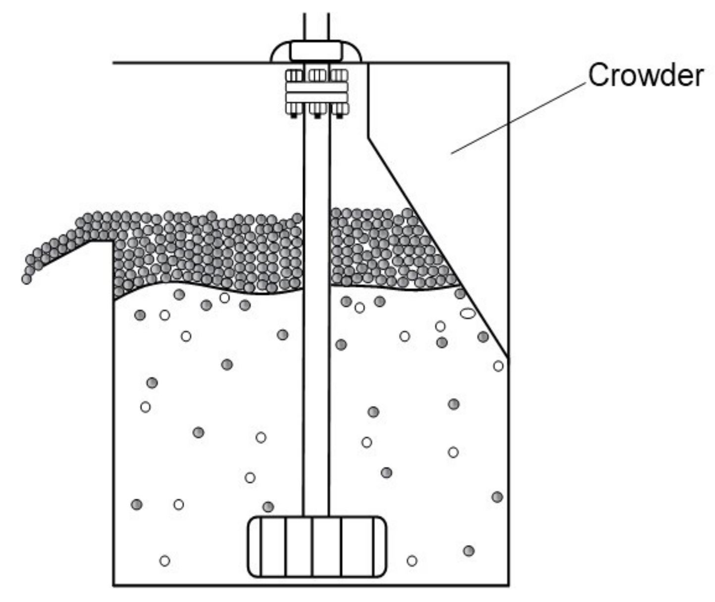


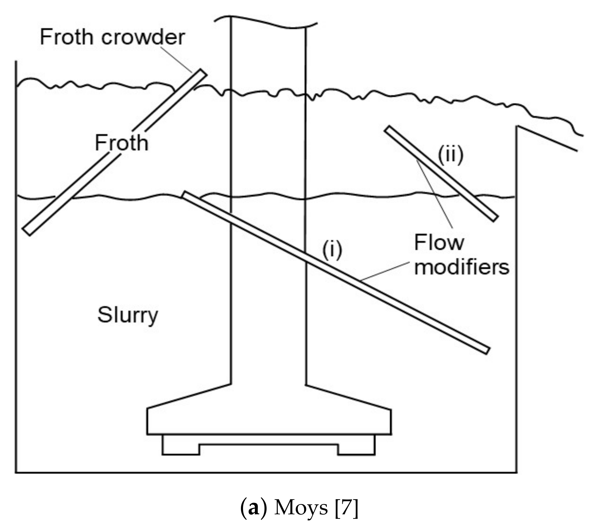


