
Investigation of Source Rock Heating and Structural Changes in the Electromagnetic Fields Using Experimental and Mathematical Modeling

 ,
,
Abstract
:1. Introduction
2. Methods and Materials
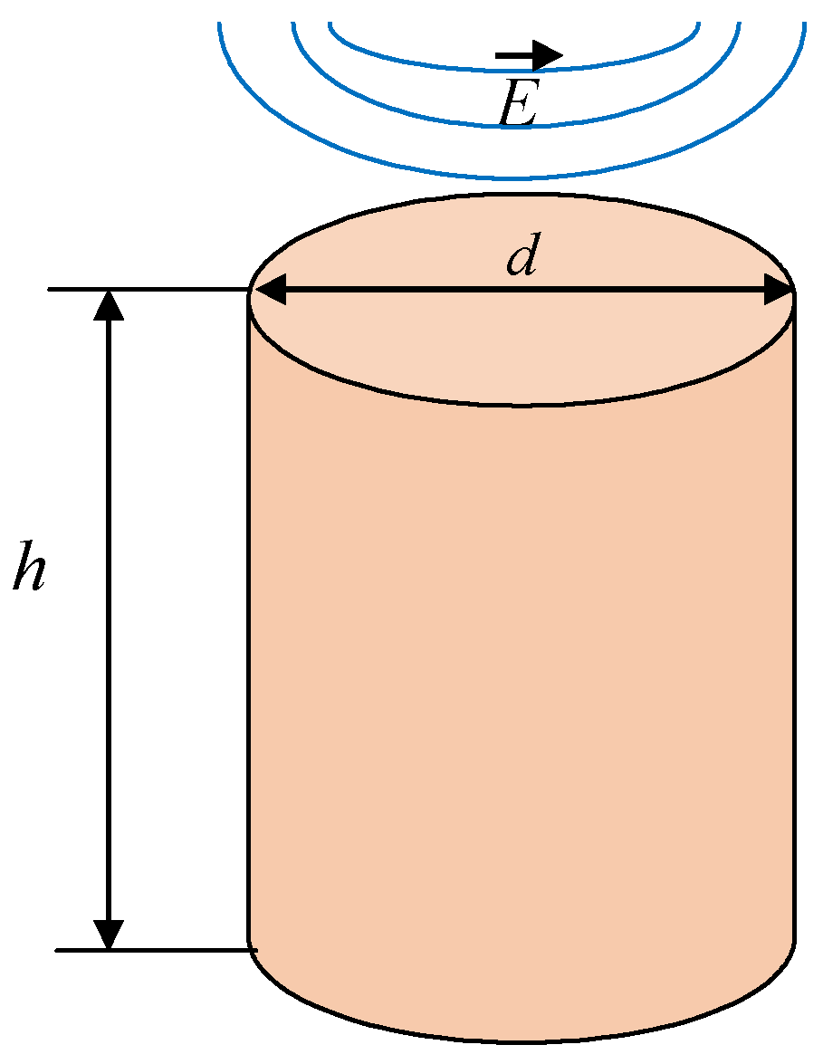
2.1. Experimental Set-Ups
2.2. Scanning Electron Microscopy
2.3. Rock-Eval Pyrolysis
2.4. X-ray Diffraction Analysis
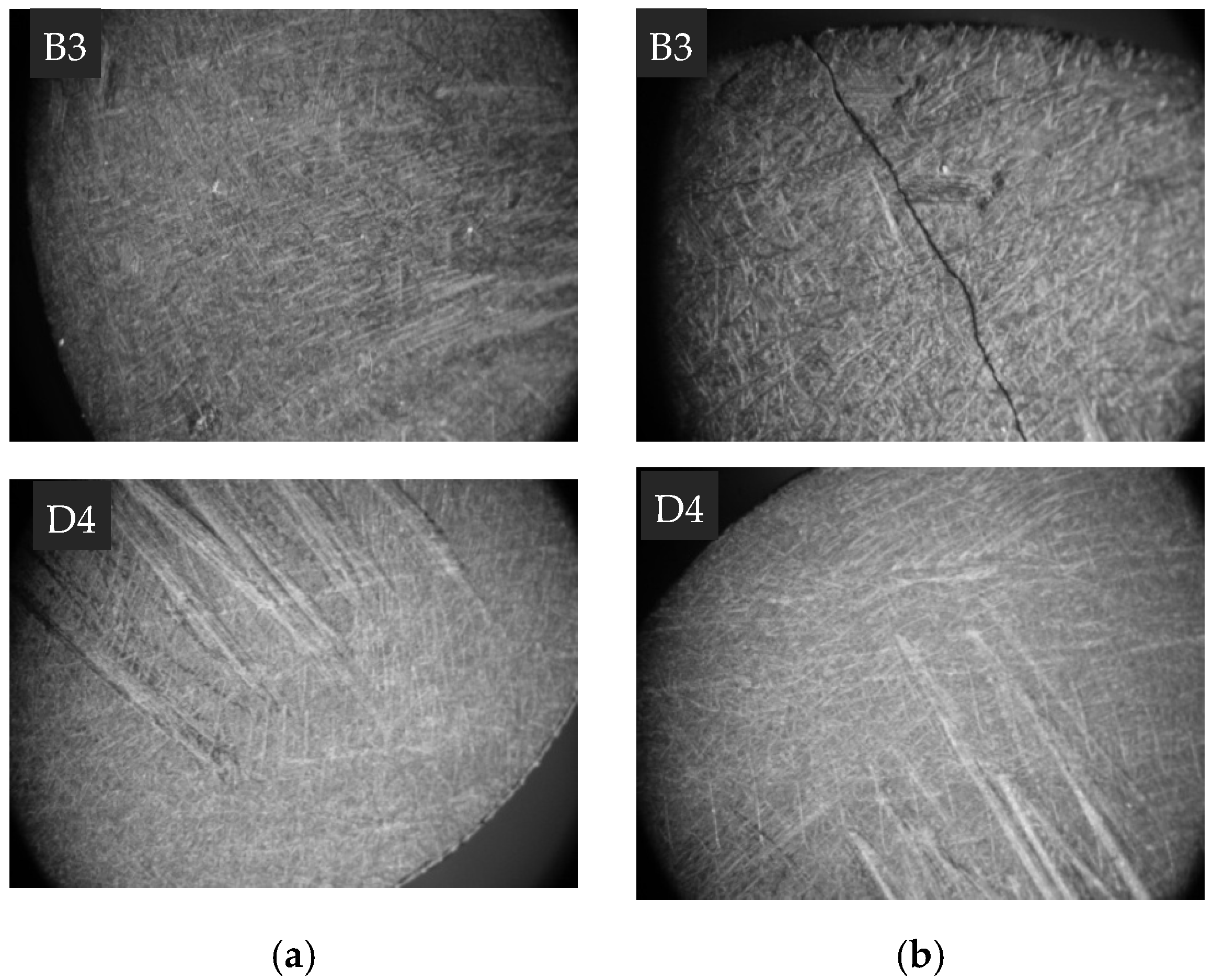
2.5. Optical Microscopy
2.6. Mathematical Model
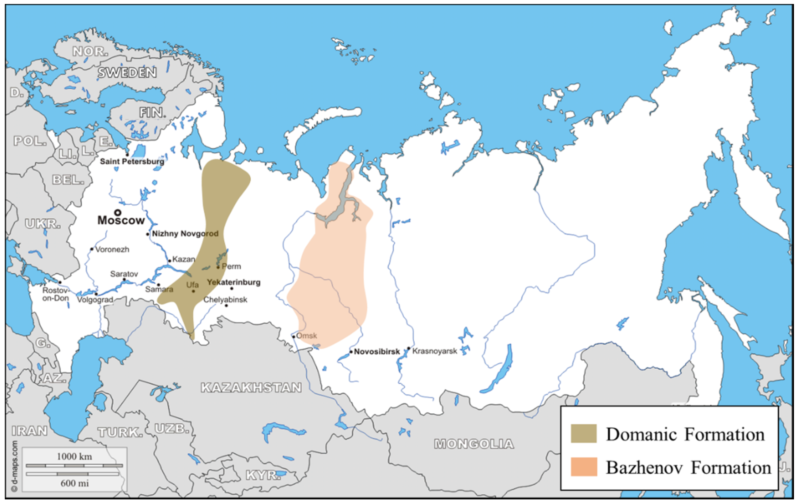
2.7. Samples
3. Results
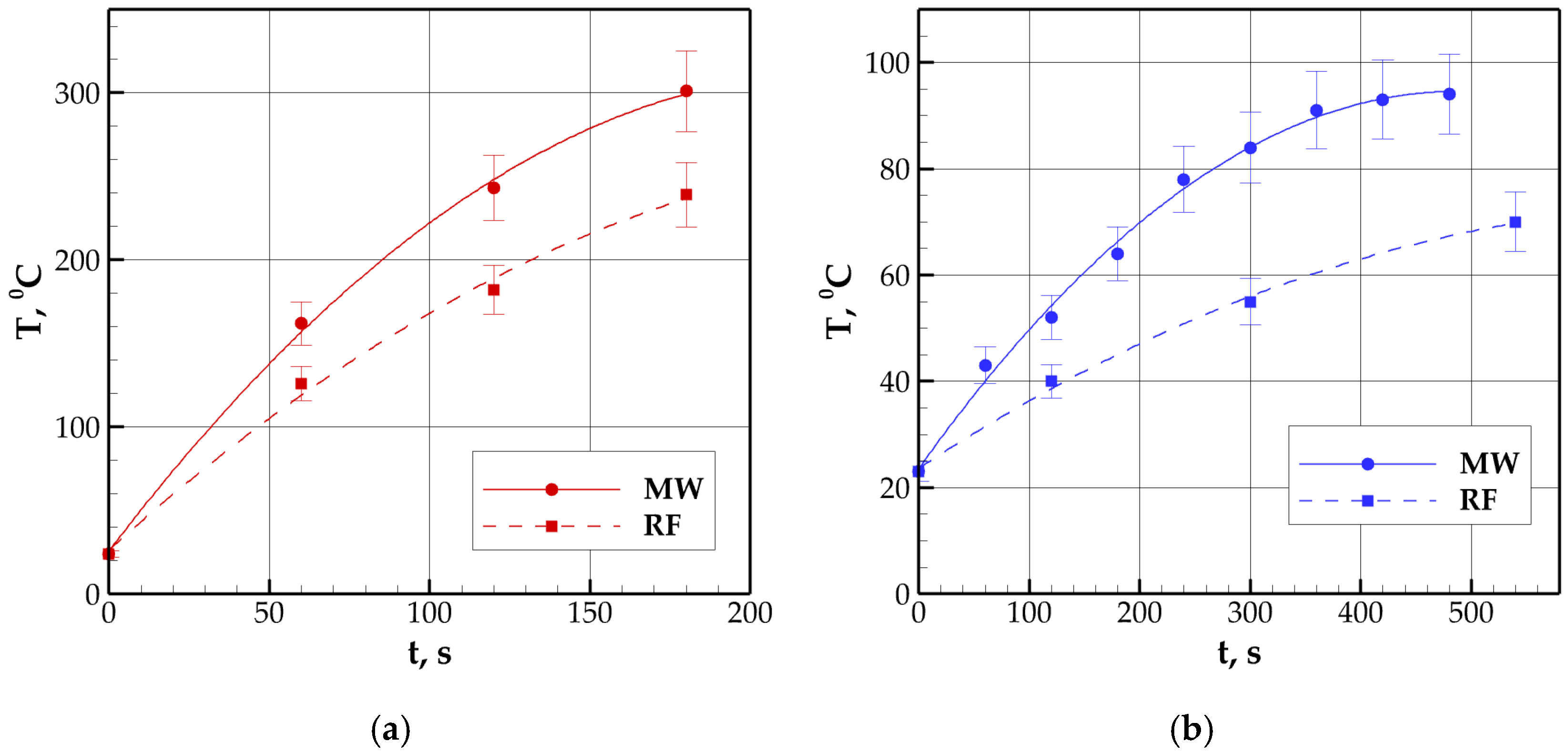
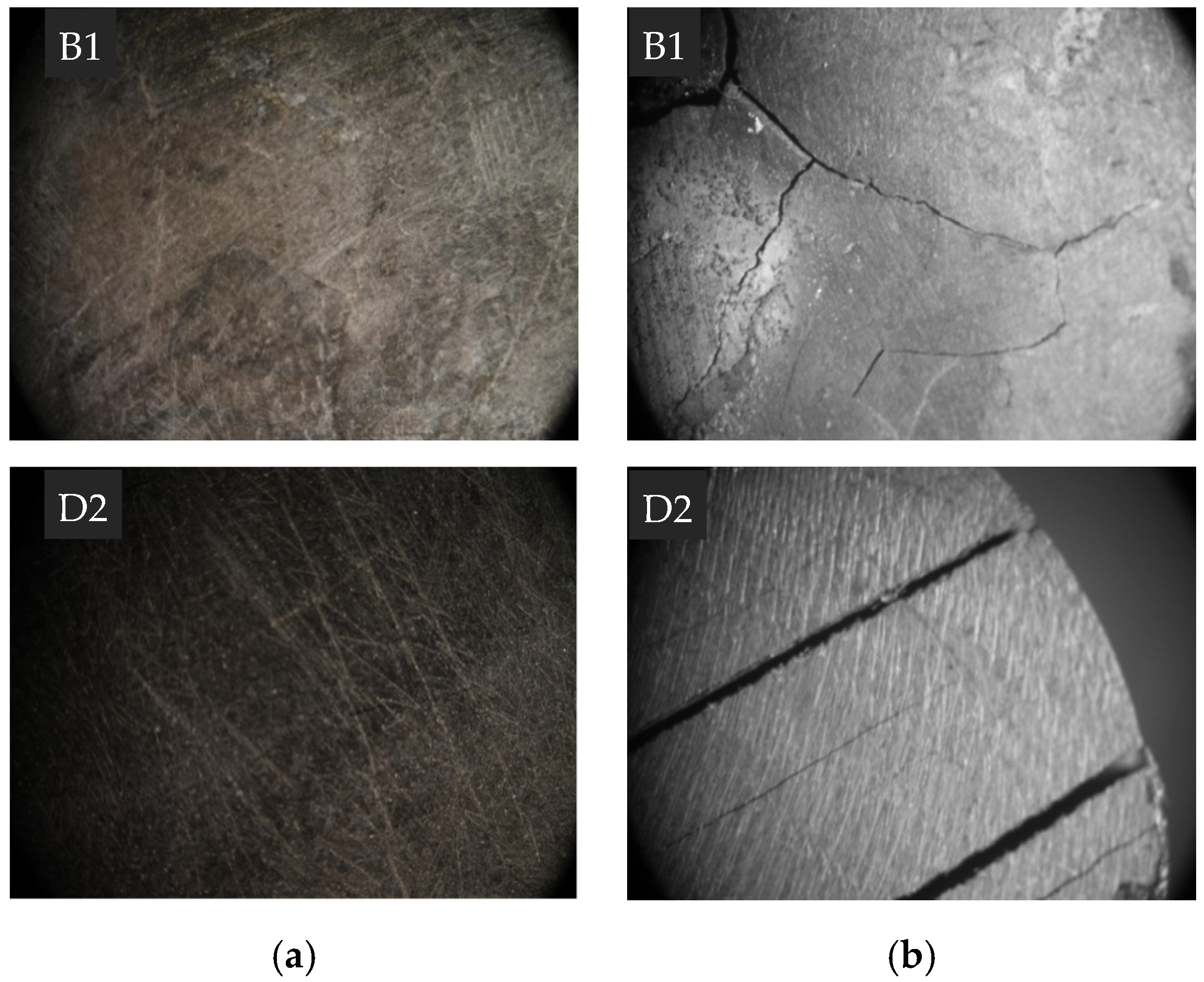
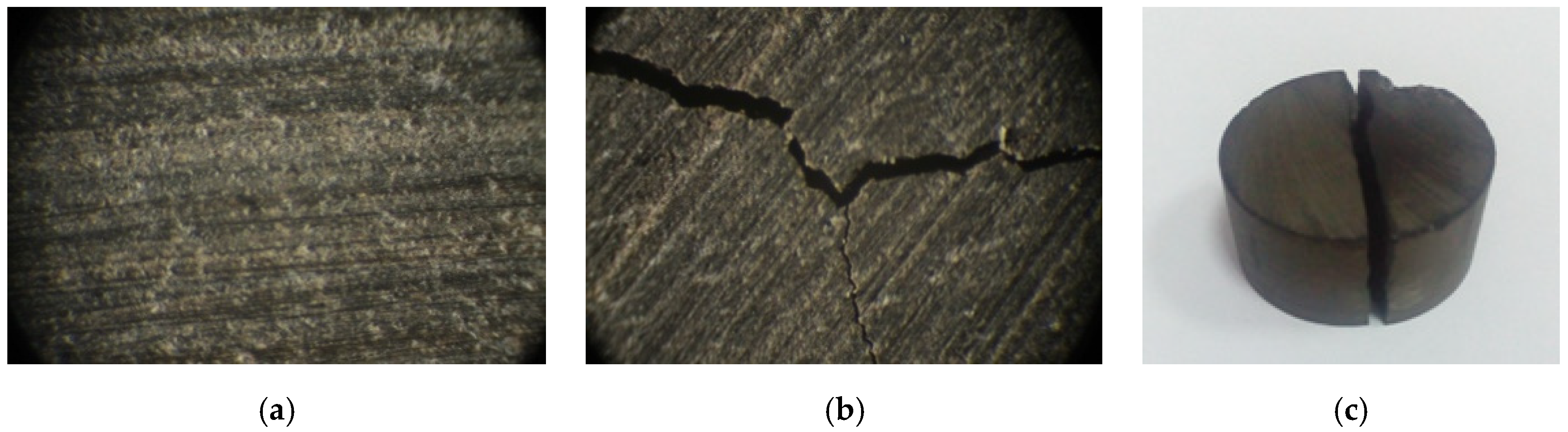
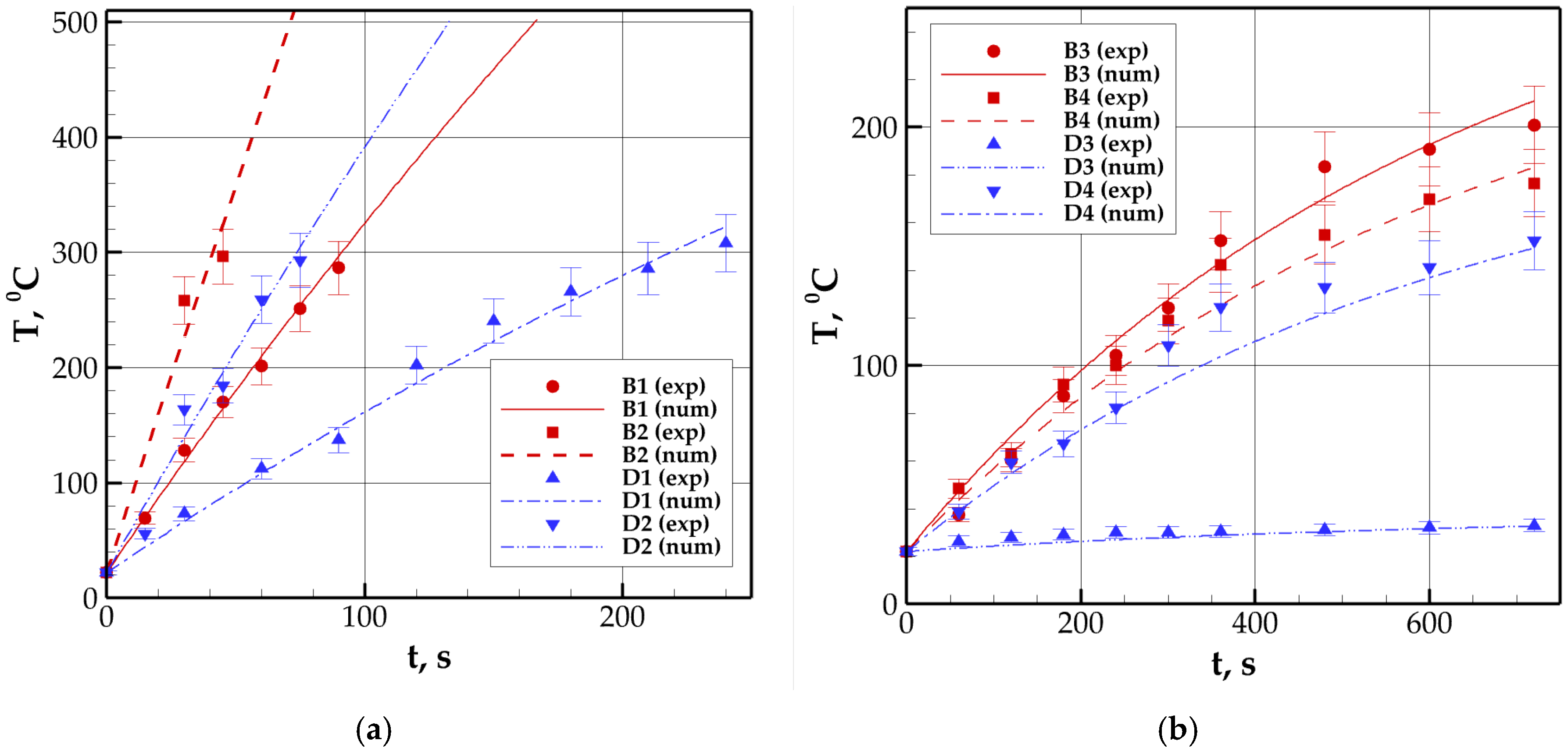
3.1. Experimental Results
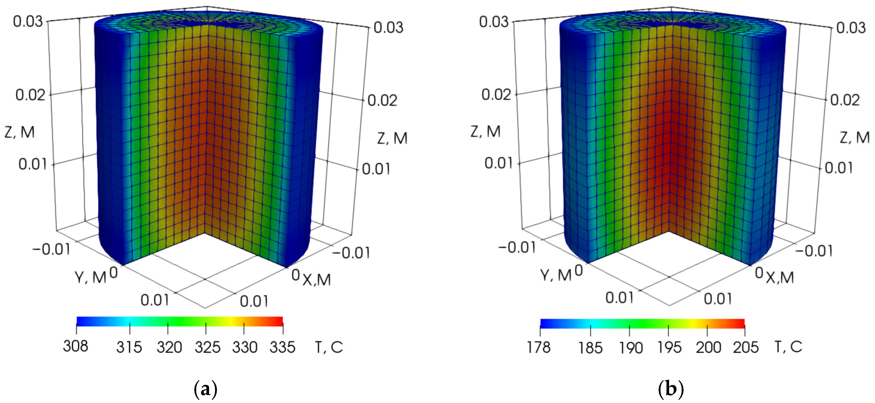
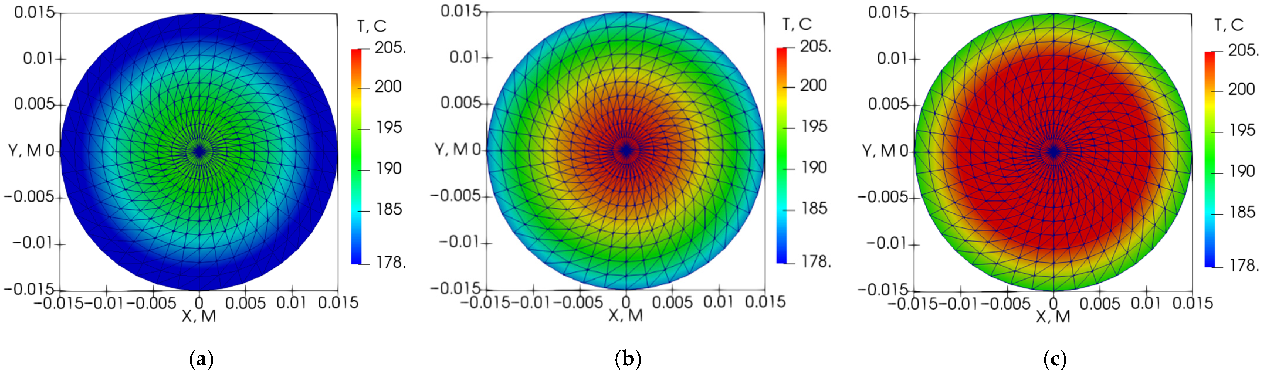
3.2. Numerical Results
4. Discussion
5. Conclusions
Author Contributions
Funding
Institutional Review Board Statement
Informed Consent Statement
Data Availability Statement
Conflicts of Interest
References
- Karamov, T.; Mukhametdinova, A.; Bogdanovich, N.; Plotnikov, V.; Khakimova, Z. Pore structure investigation of upper devonian organic-rich shales within the Verkhnekamsk depression. In Proceedings of the 19th International Multidisciplinary Scientific GeoConference SGEM 2019, Albena, Bulgaria, 30 June–6 July 2019; pp. 1045–1052. [Google Scholar]
- Mukhametdinova, A.; Kazak, A.; Karamov, T.; Bogdanovich, N.; Serkin, M.; Melekhin, S.; Cheremisin, A. Reservoir Properties of Low-Permeable Carbonate Rocks: Experimental Features. Energies 2020, 13, 2233. [Google Scholar] [CrossRef]
- Mukhametdinova, A.; Karamov, T.; Bogdanovich, N.; Borisenko, S.; Rudakovskaya, S.; Cheremisin, A. Wettability of organic-rich source rocks: Case study on Bazhenov Formation (Abalak-Bazhenov group). Adv. Geosci. 2020, 54, 195–204. [Google Scholar] [CrossRef]
- Kontorovich, A.E.; Moskvin, V.I.; Bostrikov, O.I.; Danilova, V.P.; Fomin, A.N.; Fomichev, A.S.; Kostyreva, E.A.; Melenevsky, V.N. Main oil source formations of the West Siberian Basin. Pet. Geosci. 1997, 3, 343–358. [Google Scholar] [CrossRef]
- Lazar, O.R.; Bohacs, K.M.; Schieber, J.; Macquaker, J.H.; Demko, T.M. Mudstone Primer: Lithofacies Variations, Diagnostic Criteria, and Sedimentologic-Stratigraphic Implications at Lamina to Bedset Scales; SEPM (Society for Sedimentary Geology): Tulsa, OK, USA, 2015; Volume 12. [Google Scholar]
- Balushkina, N.S.; Kalmykov, G.A.; Belokhin, V.S.; Khamidullin, R.A.; Korost, D.V. Siliceous reservoirs of the Bazhenov formation, the Sredny Nazym Oil Field, and the structure of their pore space. Mosc. Univ. Geol. Bull. 2014, 69, 91–100. [Google Scholar] [CrossRef]
- Khamidullin, R.R.; Kalmykov, G.A.; Korost, D.V.; Balushkina, N.S.; Bakay, A.I. Reservoir properties of the Bazhenov formation. In Proceedings of the SPE Russian Oil and Gas Exploration and Production Technical Conference and Exhibition, Moscow, Russia, 16–18 October 2012; p. 11. [Google Scholar]
- Gabnasyrov, A.V.; Lyadova, N.A.; Putilov, I.S.; Solovyev, S.I. Domanik shale oil: Unlocking potential. In Proceedings of the SPE Russian Petroleum Technology Conference and Exhibition, Moscow, Russia, 24–26 October 2016. [Google Scholar]
- Bushnev, D.A.; Burdelnaya, N.S. Modeling of oil generation by Domanik carbonaceous shale. Pet. Chem. 2013, 53, 145–151. [Google Scholar] [CrossRef]
- Stupakova, A.V.; Kalmikov, G.A.; Korobova, N.I.; Fadeeva, N.P.; Gotovskiy, Y.A.; Suslova, A.A.; Sautkin, R.S.; Pronina, N.V.; Bolshakova, M.A.; Zavialova, A.P.; et al. The Domanic Formation of the Volga-Ural Basin—Types of the section, formation conditions and hydrocarbon potential. Georesursy 2017, 19, 112–124. [Google Scholar] [CrossRef]
- Martemyanov, S.M. Modeling of In-Situ Heating of Oil Shale. Ph.D. Thesis, Tomsk Polytechnic University, Tomsk, Russia, 2013; 95p. [Google Scholar]
- Achinta, B.; Babadagli, T. Status of electromagnetic heating for enhanced heavy oil/bitumen recovery and future prospects: A review. Appl. Energy 2015, 151, 206–226. [Google Scholar]
- Mutyala, S.; Fairbridge, C.; Paré, J.J.; Bélanger, J.M.; Ng, S.; Hawkins, R. Microwave applications to oil sands and petroleum: A review. Fuel Process. Technol. 2010, 91, 127–135. [Google Scholar] [CrossRef]
- Kovaleva, L.A.; Zinnatullin, R.R.; Musin, A.A.; Blagochinnov, V.N.; Valiev, S.M.; Mullayanov, A.I. Method for development of watered oil reservoirs by microwave electromagnetic impact (variants). Pat. Russ. 2015, 2, 555–731. [Google Scholar]
- Davletbayev, A.Y.; Kovaleva, L.A.; Zinnatullin, R.R. Method for development of high-viscosity oil reservoir. Pat. Russ. 2010, 2, 454–532. [Google Scholar]
- Martemyanov, S.M. Investigation of the dielectric properties of shale. Mater. Methods Technol. 2011, 5, 93–101. [Google Scholar]
- Lopatin, V.V.; Martemyanov, S.M. Investigation of the dielectric properties of oil shale. Russ. Phys. J. 2012, 55, 511–515. [Google Scholar] [CrossRef]
- Zinnatullin, R.R.; Sultanguzhin, R.F. Studying dielectric properties of oil shale. J. Phys. Conf. Ser. 2020, 1675, 012102. [Google Scholar] [CrossRef]
- Sultanguzhin, R.; Kovaleva, L.; Zinnatullin, R. Radio-frequency and microwave impact on source rock. In Proceedings of the 2019 Radiation and Scattering of Electromagnetic Waves (RSEMW), Krasnodar Region, Russia, 24–28 June 2019; pp. 1–4. [Google Scholar]
- Zhu, J.; Yang, Z.; Li, X.; Wang, N.; Jia, M. Evaluation of different microwave heating parameters on the pore structure of oil shale samples. Energy Sci. Eng. 2018, 6, 797–809. [Google Scholar] [CrossRef]
- Zhu, J.; Yang, Z.; Li, X.; Qi, S.; Jia, M. Application of microwave heating with iron oxide nanoparticles in the in-situ exploitation of oil shale. Energy Sci. Eng. 2018, 6, 548–562. [Google Scholar] [CrossRef] [Green Version]
- Chen, J.H.; Georgi, D.T.; Liu, H.H. Electromagnetic thermal stimulation of shale reservoirs for petroleum production. J. Nat. Gas Sci. Eng. 2018, 59, 183–192. [Google Scholar] [CrossRef]
- Chen, J.H.; Althaus, S.M.; Liu, H.H.; Zhang, J.; Eppler, G.; Duncan, J.C.; Sun, Q. Electromagnetic-heating enhancement of source rock permeability for high recovery. Fuel 2021, 283, 118976. [Google Scholar] [CrossRef]
- Erdman, N.; Drenzek, N. Integrated Preparation and Imaging Techniques for the Microstructural and Geochemical Characterization of Shale by Scanning Electron Microscopy. AAPG Mem. Electron Microsc. Shale Hydrocarb. Reserv. 2013, 102, 7–14. [Google Scholar]
- Peters, K.E. Guidelines for Evaluating Petroleum Source Rock using Programmed Pyrolysis. Am. Assoc. Pet. Geol. Bull. 1986, 70, 318–329. [Google Scholar]
- Espitalie, J.; Bordenave, M. Rock-Eval Pyrolysis. In Applied Petroleum Geochemistry; Bordenave, M.L., Ed.; Editions Technip: Paris, France, 1993; pp. 237–361. [Google Scholar]
- Incropera, F.P.; DeWitt, D.P.; Bergman, T.L.; Lavine, A.S. Fundamentals of Heat and Mass Transfer, 6th ed.; John Wiley & Sons: Hoboken, NJ, USA, 2007; pp. 57–94. [Google Scholar]
- Landau, L.D.; Lifshitz, E.M. Electrodynamics of Continuous Media, 2nd ed.; Pergamon Press: Oxford, UK, 1984; pp. 358–371. [Google Scholar]
- Kovaleva, L.A.; Zinnatullin, R.R.; Sultanguzhin, R.F.; Sektarov, E.S.; Shashkov, A.V. Experimental study of the influence of high-frequency and microwave electromagnetic fields on oil shales. Bull. Bashkir Univ. 2019, 24, 43–48. [Google Scholar] [CrossRef] [Green Version]
- Yudin, V.A.; Korolev, A.V.; Afanaskin, I.V.; Volpin, S.G. Heat Capacity and Thermal Conductivity of Rocks and Fluids of the Bazhenov Formation—Initial Data for Numerical Modeling of Thermal Development Methods; FGU FNTS NIISI RAN: Moscow, Russia, 2015; p. 225. [Google Scholar]
- Kazak, E.S.; Kozlova, E.V.; Karamov, T.I.; Bogdanovich, N.N.; Chizhov, D.B. Connate water of the organocarbonate shale rocks of Domanic deposits. Oil Ind. J. 2021, 5, 84–89. [Google Scholar]
- Kazak, E.S.; Rodkina, I.A.; Kazak, A.V. Free and Bound Water Content in Tight Rocks of Bazhenov Formation. IOP Conf. Ser. Earth Environ. Sci. 2020, 459, 022094. [Google Scholar] [CrossRef]


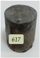
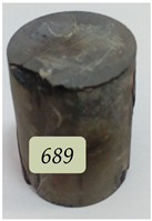
| Sample B1 | Sample B2 | Sample B3 | Sample B4 | Sample B5 |
|---|---|---|---|---|
 | 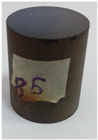 | 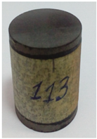 | 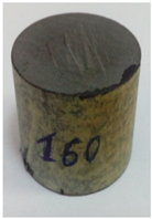 |  |
| MW 1 | RF 2 | MW and RF | ||
| Sample D1 | Sample D2 | Sample D3 | Sample D4 | Sample D5 |
|---|---|---|---|---|
 |  | 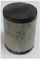 | 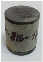 |  |
| MW | RF | MW and RF | ||
| Sample | S1, mg HC/g Rock | S2, mg HC/g Rock | TOC, wt% |
|---|---|---|---|
| B1 | 5.06 | 84.2 | 18.48 |
| B2 | 8.39 | 71.88 | 11.01 |
| B3 | 8.22 | 21.45 | 3.91 |
| B4 | 3.50 | 10.83 | 5.45 |
| D1 | 0.73 | 12.62 | 4.5 |
| D2 | 0.35 | 2.43 | 1.72 |
| D4 | 0.79 | 8.62 | 2.38 |
| Sample | Quartz, wt% | Clay Minerals, wt% | Calcite, wt% | Dolomite, wt% | Pyrite, wt% |
|---|---|---|---|---|---|
| B1 | 52 | 38 | 7 | 0 | 3 |
| B2 | 47 | 49 | 0 | 0 | 4 |
| B3 | 85 | 13 | 0 | 0 | 2 |
| B4 | 12 | 6 | 81 | 0 | 1 |
| D2 | 1 | 0 | 98 | 1 | 0 |
| D3 | 10 | 0 | 87 | 3 | 0 |
| D4 | 3 | 0 | 92 | 5 | 0 |
| Microwave Influence | Radio-Frequency Influence | |||||||
|---|---|---|---|---|---|---|---|---|
| Sample | B1 | B2 | D1 | D2 | B3 | B4 | D3 | D4 |
| , °C/s | 2.90 | 6.10 | 1.20 | 3.60 | 0.25 | 0.21 | 0.015 | 0.18 |
| , °C/s | 3.00 | 6.72 | 1.25 | 3.70 | 0.26 | 0.22 | 0.015 | 0.18 |
| , W/cm3 | 8.99 | 19.48 | 4.21 | 10.96 | 1.22 | 1.04 | 0.07 | 0.87 |
Publisher’s Note: MDPI stays neutral with regard to jurisdictional claims in published maps and institutional affiliations. |
© 2021 by the authors. Licensee MDPI, Basel, Switzerland. This article is an open access article distributed under the terms and conditions of the Creative Commons Attribution (CC BY) license (https://creativecommons.org/licenses/by/4.0/).
Share and Cite
Kovaleva, L.; Zinnatullin, R.; Musin, A.; Kireev, V.; Karamov, T.; Spasennykh, M. Investigation of Source Rock Heating and Structural Changes in the Electromagnetic Fields Using Experimental and Mathematical Modeling. Minerals 2021, 11, 991. https://doi.org/10.3390/min11090991
Kovaleva L, Zinnatullin R, Musin A, Kireev V, Karamov T, Spasennykh M. Investigation of Source Rock Heating and Structural Changes in the Electromagnetic Fields Using Experimental and Mathematical Modeling. Minerals. 2021; 11(9):991. https://doi.org/10.3390/min11090991
Chicago/Turabian StyleKovaleva, Liana, Rasul Zinnatullin, Airat Musin, Victor Kireev, Tagir Karamov, and Mikhail Spasennykh. 2021. "Investigation of Source Rock Heating and Structural Changes in the Electromagnetic Fields Using Experimental and Mathematical Modeling" Minerals 11, no. 9: 991. https://doi.org/10.3390/min11090991