Abstract
The cone crusher is the main equipment in the particle crushing process. The productivity of the cone crusher is determined by the motion characteristics of particles passing through the crushing chamber. In order to accurately describe the motion characteristics of the particles, the influence of the spatial compound motion of the mantle rotates around the central axis of the cone crusher and its central axis on the motion characteristics of the particles is investigated, then the improved motion model is established. Through the coordinate system transformation matrix, the motion characteristics of the particles including spatial sliding, free-falling, and spatial compound falling are solved. The applicability and accuracy of the improved model in describing the motion characteristics of the particle were verified through the experiment using a reduced-scale experimental cone crusher to simulate the motion characteristics of the particle. Based on the improved model, the motion characteristics of the particles in the CF11 hydraulic cone crusher can be simulated. With the decrease in height, the motion characteristics of particles gradually change from spatial sliding to spatial compound falling and finally to free-falling. The particles deflect circumferentially around the central axis of the cone crusher. The circumferential deflection of particles is directly related to the motion characteristics including spatial sliding and spatial compound falling. The improved model provides a theoretical basis for the high energy design of the crushing chamber and productivity improvement of the cone crusher.
1. Introduction
The cone crusher is a high-efficiency particle crushing equipment that has the advantages of high productivity, good crushing product quality, and high energy utilization [1]. It is widely used in a variety of industrial departments, such as mines, construction, and the chemical industry. Productivity is one of the essential performance indexes of cone crushers, determined by the motion characteristics of particles passing through the crushing chamber in the dynamic crushing process. The improved model can simulate the motion characteristics of particles through the structural and operating parameters of the cone crusher and provide theoretical guidance for the design of the crushing chamber and the optimization of production performance. Therefore, the research on the motion model of particles has important theoretical significance and practical value.
The motion characteristics of particles in the crushing chamber were investigated theoretically by many scholars. Gauldie [2,3] proposed an empirical model to describe the motion characteristics of particles based on the structure of crushing equipment. Briggs [4] developed the motion equation of particles according to the force analysis of particles in the crushing chamber. Evertsson [5,6] investigated the motion characteristics of particles including sliding and free-falling in the two-dimensional coordinate system. Based on the continuum model of granular materials [7], Oliver et al. [8] explored particle motion in the crushing chamber which was simplified to a two-dimensional channel. With the rapid advancement of computer simulation technology, the discrete element method (DEM) is being used to investigate the motion characteristics of particles in the crushing chamber [9,10,11]. Herbst et al. [12] firstly used the DEM to simulate the crushing process of the cone crusher, and then studied the motion characteristics of particles in the one-side crushing chamber. Li et al. [13] used a chute instead of the crushing chamber to explore the motion characteristics of particles. Delaney et al. [14] presented a non-spherical particle breakage method for simulating the particle motion in the crushing chamber. Quist et al. [15] developed a DEM modeling framework for cone crusher simulation and employed a bonded particle model to simulate particle motion. Johansson et al. [16] used commercial software to simulate the crushing process of laboratory-scale cone crushers and the path of particles passing through the crushing chamber was intuitively determined. However, the particularities of the cone crusher structure in the existing model are not taken into account, the influence of the spatial compound motion of the mantle on the motion characteristic of the particles is ignored, and the theoretical spatial analysis of the force and acceleration of the particles in the dynamic crushing process is not carried out, which cannot accurately describe the motion characteristics of the particle. Therefore, it is necessary to establish a more accurate model for the motion characteristics of the particle in the cone crusher, which considers the influence of the spatial compound motion of the mantle.
The coordinate system transformation matrix is obtained by analyzing the structure of the cone crusher. The influence of the spatial compound motion of the mantle on the motion characteristics of particles is investigated, which rotates around the central axis of the cone crusher and its central axis, then the improved motion model of particles in the cone crusher considering the spatial compound motion of the mantle is established. The improved model improves the simulation accuracy of the motion characteristics of particles in the crushing chamber of the cone crusher, which lays a theoretical foundation for the development of the high-energy crushing chamber and the optimization of parameters.
2. The Spatial Compound Motion of the Mantle
The crushing chamber of the cone crusher is composed of the mantle and concave, which are responsible for the efficient crushing of particles. The spatial compound motion of the mantle which is in direct contact with the particles during the dynamic crushing process has an important influence on the motion characteristics of particles. Therefore, it is necessary to investigate the motion of the mantle.
The structure of the cone crusher is shown in Figure 1. The power is imported into the cone crusher through the belt pulley so that the rotation of the eccentric sleeve is driven by the gear group. The eccentric sleeve is assembled in the main shaft which the upper end is fixed by the spherical plain bearing and the lower end is supported by the spherical thrust bearing at the top of the hydraulic cylinder. The rotation of the eccentric sleeve forces the main shaft to rotate around the central axis of the cone crusher. The mantle assembled on the main shaft rotates eccentrically around the central axis of the cone crusher and makes reciprocating motion relative to the concave installed on the inner surface of the shell.
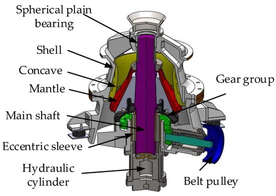
Figure 1.
The cross-sectional view of the structure of a hydraulic cone crusher with a single hydraulic cylinder at the bottom.
The mantle is mounted on the main shaft of the cone crusher. The mantle rotates eccentrically around the central axis of the cone crusher, as shown in Figure 2. Thus, the particles in the crushing chamber are broken due to the squeeze caused by the reciprocating motion of the mantle to the concave. Due to the friction between the mantle surface and the surface of the broken particles, the rotating motion of the mantle around its central axis is caused, as shown in Figure 2. The rotation direction of the mantle around its central axis is opposite to the rotation direction of the mantle around the central axis of the cone crusher.
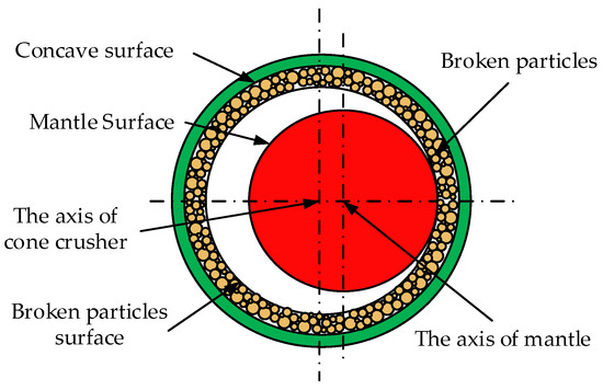
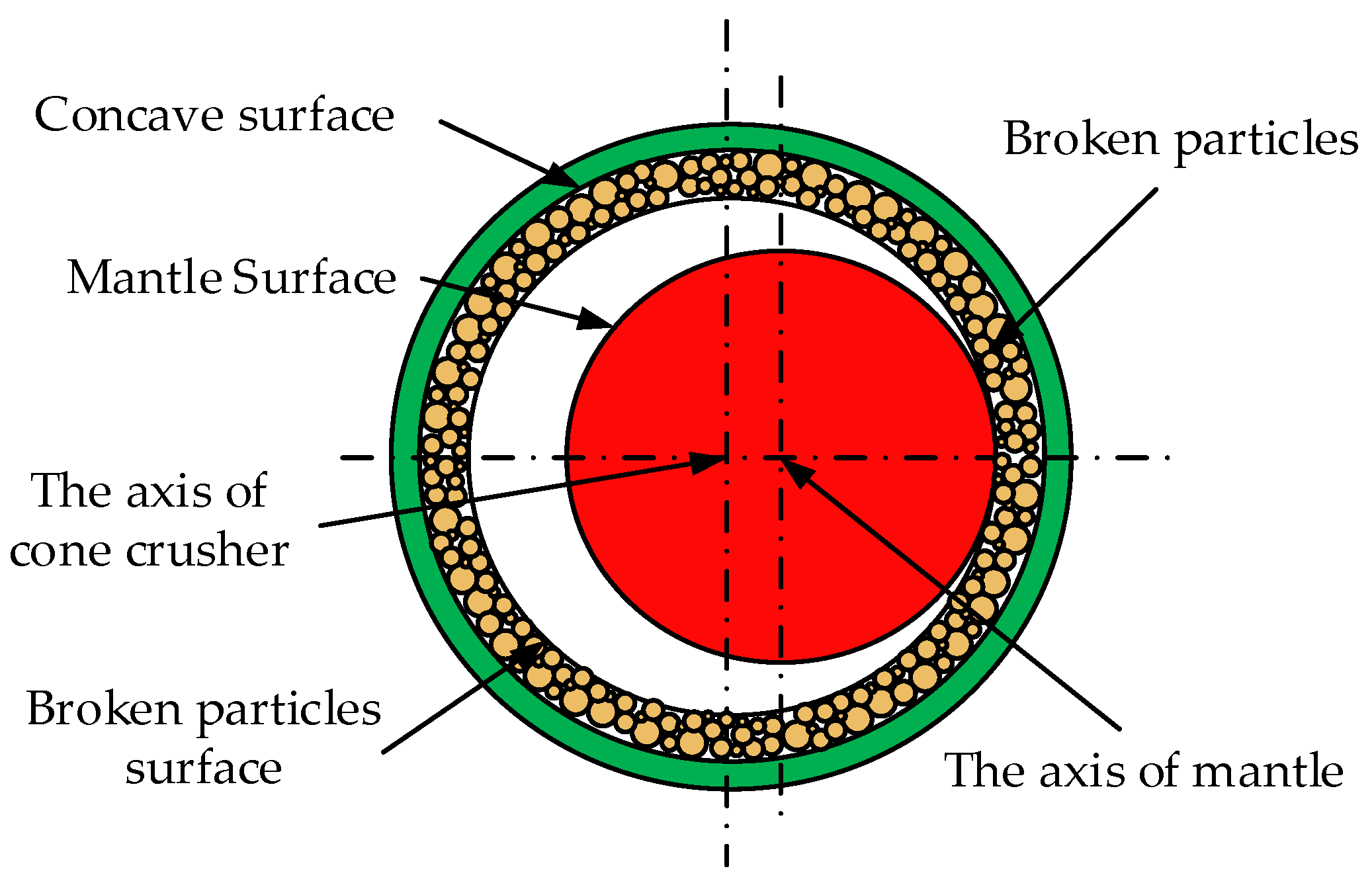
Figure 2.
The cross section of cone crusher.
Due to the constraint imposed by the equipment structure, the nature of the power drive, and the friction created by broken particles, the mantle is determined to perform a spatial compound motion that rotates around the central axis of the cone crusher and its central axis. Due to the spatial compound motion of the mantle, the particles are subjected to the combined action of multiple forces with varying sizes and directions in the dynamic crushing process. Therefore, the particles in the crushing chamber have a variety of motion characteristics.
3. The Motion Characteristics of Particles in Crushing Chamber
In order to accurately describe the motion characteristics of particles in the crushing chamber of the cone crusher, the motion characteristics of particles in the multiple crushing cycles must be solved. So, it is necessary to analyze the force and acceleration components of particles before establishing the model of motion characteristics of particles.
3.1. The Coordinate System Transformation Matrix of Cone Crusher
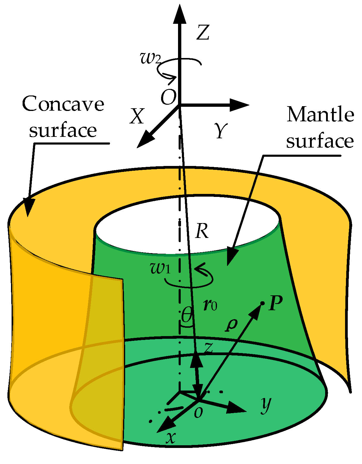
Since the particles are directly contacted with the mantle during the dynamic crushing process in the crushing chamber, the motion characteristics of particles are significantly affected by the spatial compound motion of the mantle. The mantle rotates around the central axis of the cone crusher and its central axis. Thus, the motion of particles in direct contact with the mantle can be synthesized by the relative motion of particles relative to the mantle surface and the traction motion of the contact point between the mantle surface and the particles. Hence, a mathematical transformation must be established between the moving coordinate system fixed on the mantle surface and the global coordinate system fixed on the working plane of the cone crusher. According to an analysis of the structure of the cone crusher and the motion characteristics of the mantle, the coordinate system transformation matrix is established. The coordinates and vectors in a moving coordinate system can be converted into a global coordinate system. Thus, it provides theoretical support for the establishment of the motion model of particles in the same coordinate system.
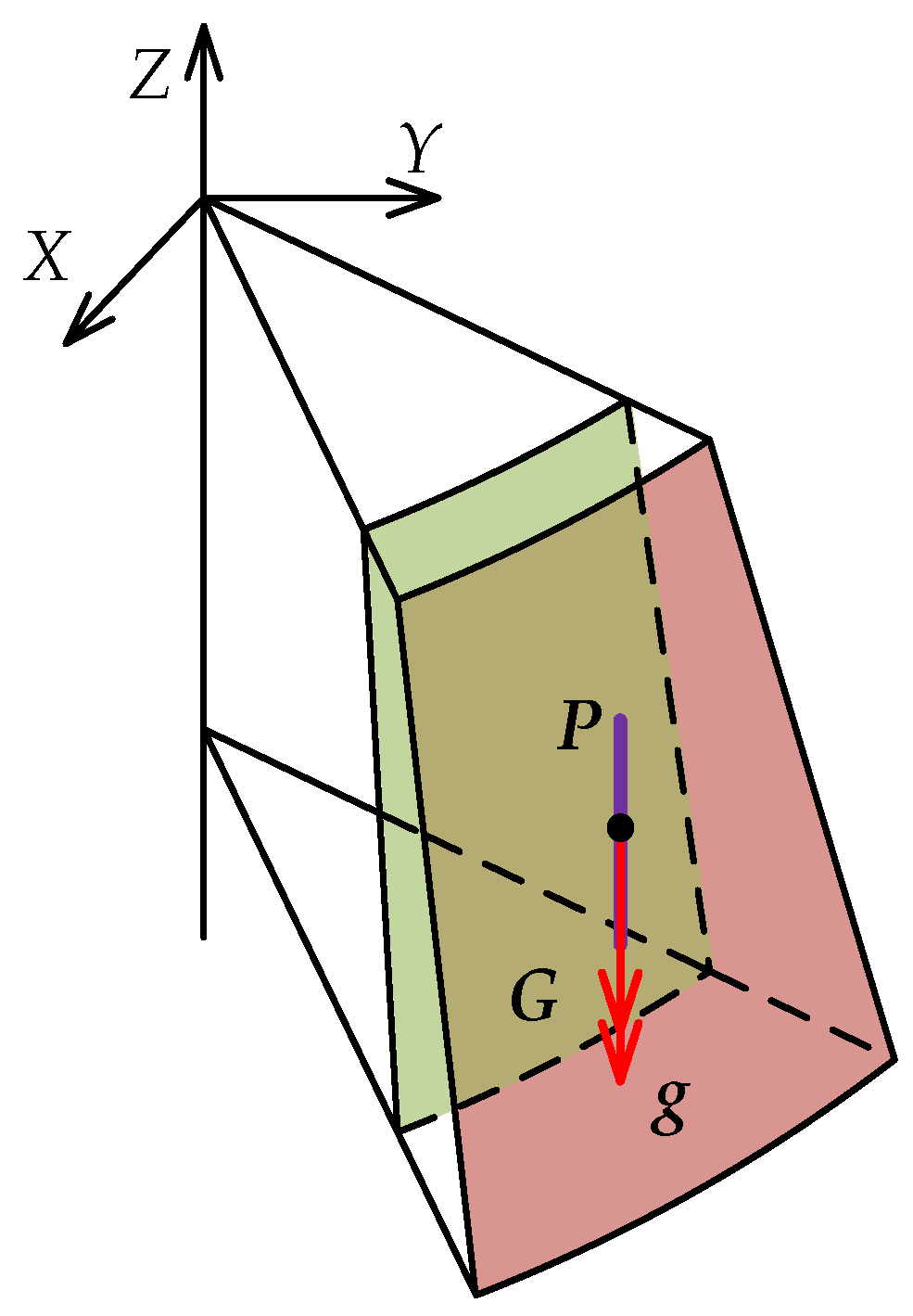
As shown in Figure 3, the Z-axis of the global coordinate system OXZY coincides with the central axis of the cone crusher, and the coordinate origin O is located at the center point of the spherical plain bearing. The z-axis of the moving coordinate system oxyz coincides with the central axis of the main shaft, and the coordinate origin o is located at the center point of the mantle bottom. The mantle rotates around the Z-axis with angular velocity w2 and rotates around the z-axis with angular velocity w1. R denotes the distance between the origin O of the global coordinate system OXZY and the origin o of the moving coordinate system oxyz. The angle formed by the Z-axis and the z-axis is denoted by θ. The position vector of the coordinate origin o in the global coordinate system OXZY is denoted by r0. The position vector of particle P is represented as ρ.
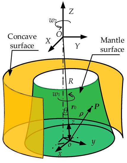
Figure 3.
The location of the moving coordinate system and the global coordinate system.
Based on the coordinate system transformation theory [17], the coordinate system transformation matrix which converts the coordinates and vectors from the moving coordinate system to the global coordinate system is established as shown in Equations (1) and (2):
where PXYZ is the coordinate of particles in the global coordinate system and pxyz is the coordinate of particles in the moving coordinate system, X, Y, Z, x, y and z denote the components of coordinates in the global coordinate system and the moving coordinate system, NX, NY, NZ, nx, ny and nz are the components of vectors in the global coordinate system and the moving coordinate system, kxX, kxY, kxZ, kyX, kyY, kyZ, kzX, kzY, kzZ, xX, yY and zZ are the elements of the coordinate system transformation matrix, K4 and K3 denote the coordinate system transformation matrix of the coordinates and vectors.
According to the structural and operating parameters of cone crusher, the elements in the coordinate system transformation matrix can be expressed as follows:
3.2. Analysis of Motion Characteristics of Particles in Crushing Chamber
Due to the spatial compound motion of the mantle which rotates around the central axis of the cone crusher and its central axis, the particles in direct contact with the mantle are subjected to the combined action of multiple forces with time-varying size and direction. Therefore, the particles in the crushing chamber have a variety of motion characteristics.
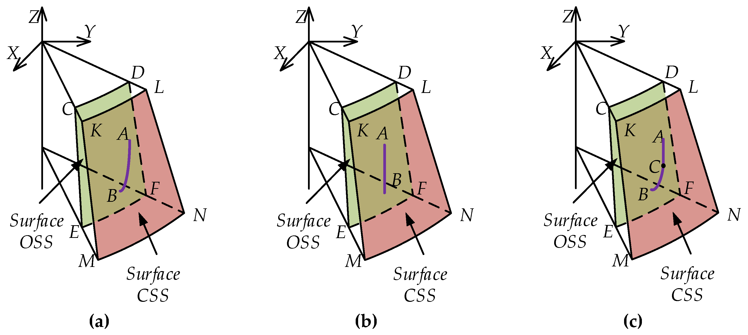
According to the extent to which particles come into contact with the mantle during the crushing cycle, the motion characteristics of particles can be classified as spatial sliding, which is always in contact with the mantle, free-falling which is never in contact with the mantle, and spatial compound falling, as shown in Figure 4.
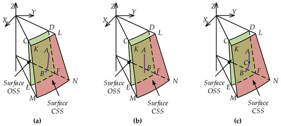
Figure 4.
The motion characteristics of particles. (a) The spatial sliding. (b) The free-falling. (c) The spatial compound falling.
The mantle rotates around the central axis of the cone crusher. When the mantle moves from the concave to the limit position, the surface OSS (Open Side Setting) of the mantle is formed, as shown in surface CDEF in Figure 4. When the mantle moves towards the concave to the limit position, the surface CSS (Closed Side Setting) of the mantle is formed, as shown in surface KLMN in Figure 4. As shown in Figure 4a, the motion characteristic of the particle is spatial sliding. The particle always contacts with the mantle surface during spatial sliding from point A of the surface CSS to point B of the surface OSS. The particle not only slides along the mantle surface but also makes a compound motion with the mantle which rotates around the central axis of the cone crusher and its central axis. As shown in Figure 4b, the motion characteristic of the particle is free-falling. When the particle leaves the mantle from point A of the surface CSS and falls freely, the mantle performs a spatial compound motion that rotates around the central axis of the cone crusher and its central axis. At a certain time, the particle contacts with the mantle surface at point B. As shown in Figure 4c, the motion characteristic of the particle is spatial compound falling of free-falling and spatial sliding. The particle falls freely from point A of the surface CSS. The particle contacts with the mantle surface at point C. After the contact, the particle not only slides along the mantle surface but also makes a compound motion with the mantle rotating around the central axis of the cone crusher and its central axis until it moves to point B of the surface OSS.
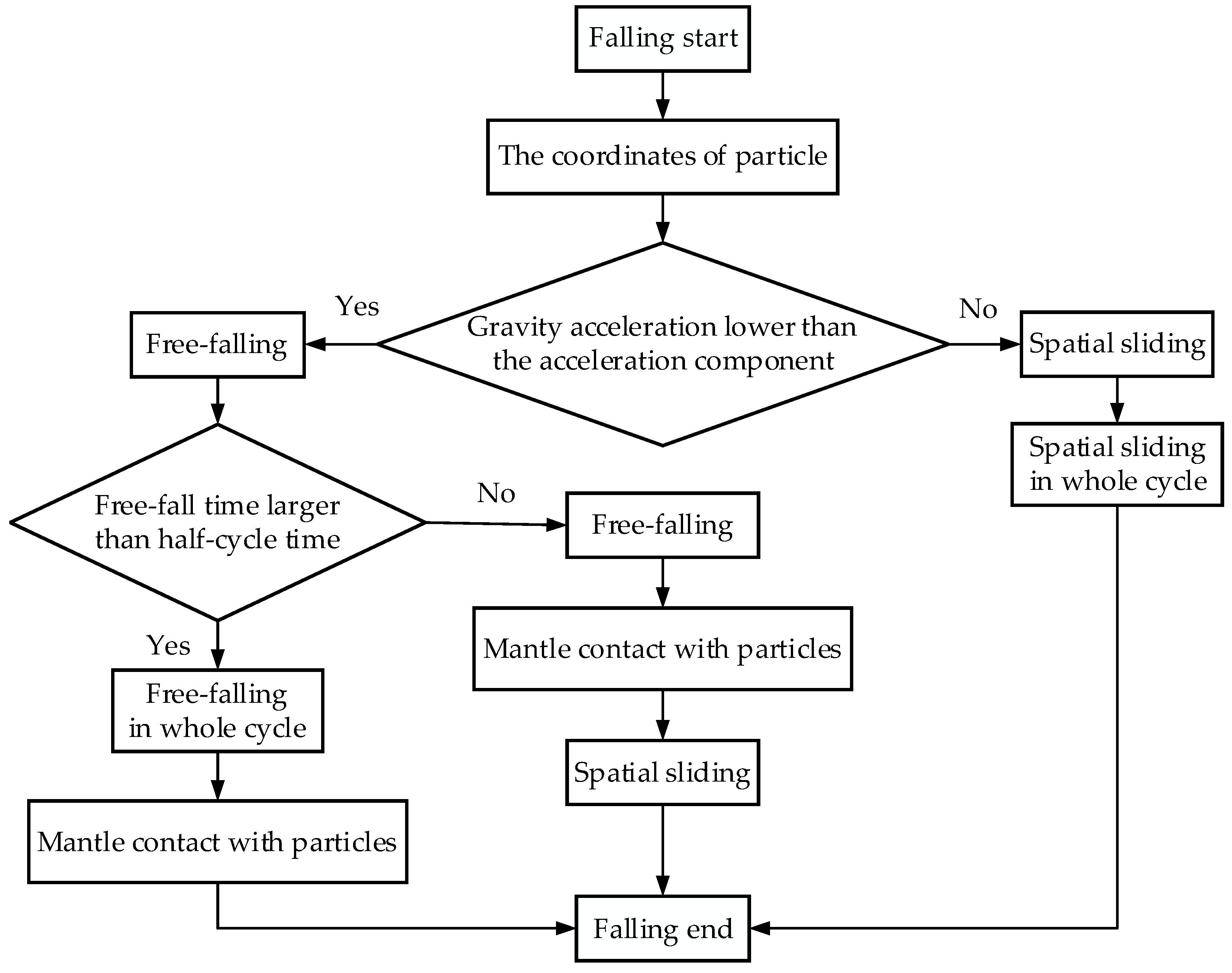
The influence of the spatial compound motion of the mantle which rotates around the central axis of the cone crusher and its central axis on the motion characteristics of the particles is considered, the motion characteristics of particles during a single crushing cycle can be determined by analyzing the acceleration of particles. Through repeated analysis of motion characteristics of particles, all motion characteristics of particles in the crushing chamber during dynamic crushing can be obtained. Based on the analysis of position coordinates and acceleration of the particle, a flow chart for the analysis of motion characteristics of the particle can be generated, as shown in Figure 5.
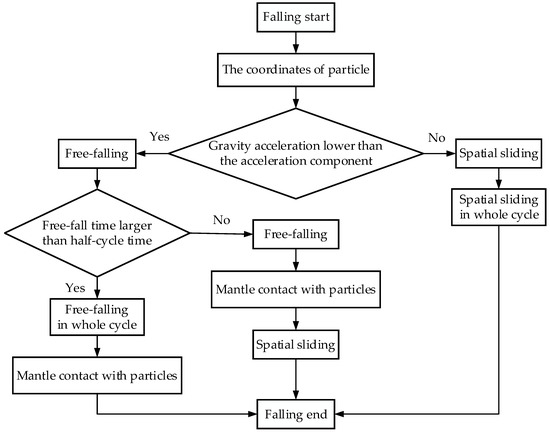
Figure 5.
The flow chart of motion characteristics analysis of particles.
When the particle begins to fall, the initial position coordinates of the particle are determined. According to the structural and operating parameters of the cone crusher, the absolute acceleration component of the contact point between the mantle surface and the particle in the direction of gravity is determined. The motion characteristics of the particle are determined by comparing the gravitational acceleration and the acceleration component of the contact point. If the gravitational acceleration of the particle is less than the acceleration component of the contact point, the free-falling acceleration of the particle is less than the acceleration of the mantle surface moving away from the particles. Therefore, the motion characteristic of the particle is free-falling. By comparing the free-falling time of the particle and the half-cycle time of mantle rotation, the motion characteristic of the particle can be further determined. If the free-falling time of the particle is larger than the half-cycle time of mantle rotation, the particle contacts with the mantle surface during the movement from the surface OSS to the surface CSS. Therefore, the motion characteristic of the particle in the whole cycle is determined as free-falling. If the free-falling time of the particle is less than the half-cycle time of mantle rotation, the particle contacts with the mantle surface during the movement from the surface OSS to the surface CSS. The particle slides along the mantle surface and moves with the mantle surface until the mantle reaches the surface OSS. Thus, the motion characteristic of the particle is determined as the spatial compound falling consisting of free-falling and spatial sliding. If the gravitational acceleration of the particle is larger than the acceleration component of the contact point, the free-falling acceleration of the particle is larger than the acceleration of the mantle surface moving away from the particles. The particle slides along the mantle surface and continues to move with the mantle surface until the mantle reaches the surface OSS. Thus, the motion characteristic of the particle in the whole cycle is determined as spatial sliding.
By analyzing the motion characteristics of particles during a single crushing cycle, the judging standards for the three types of motion characteristics are clarified, and the analysis process of motion characteristics of particles is obtained, which provides theoretical guidance for establishing the motion model of particles.
3.2.1. The Motion Characteristics of Spatial Sliding
As shown in Figure 6, a certain particle P in the crushing chamber is selected as the research object. In a crushing cycle, the particle P not only slides along the mantle surface but also moves with the mantle which rotates around the center axis of the cone crusher and rotates around its center axis. Therefore, the absolute acceleration aP of particle P is composed of the acceleration ao of the origin of the moving coordinate system, the normal acceleration an and the traction acceleration aτ of the contact point between the mantle surface and the particle, the relative acceleration ar of the particle sliding on the mantle surface and the Coriolis acceleration ac generated by the motion of the moving coordinate system.
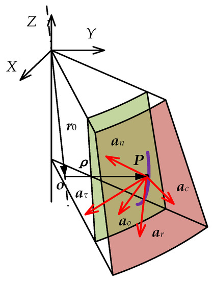
Figure 6.
The acceleration components of spatial sliding particle.
The absolute acceleration aP of particle P which motion characteristic is spatial sliding can be obtained by Equation (15).
The origin o of the moving coordinate system oxyz is fixed at the center of the bottom of the mantle. The moving coordinate system rotates around the central axis of the cone crusher. Therefore, the acceleration ao of the moving coordinate system can be expressed as Equation (16).
The relative acceleration ar of the particle P sliding on the mantle surface can be expressed by the second derivative of particle coordinate in moving coordinate system oxyz:
Since the moving coordinate system oxyz rotates around the central axis oz of the mantle, the normal acceleration an of the contact point between the mantle surface and the particle can be expressed by Equation (18).
Similarly, the tangential acceleration aτ of the contact point between the mantle surface and the particle can be expressed by Equation (19).
The Coriolis acceleration ac of the contact point between the mantle surface and the particle can be expressed as Equation (20).
Therefore, the absolute acceleration aP of particle P in the global coordinate system OXYZ is established.
The absolute acceleration aP of particle P is decomposed into three coordinate axes in the global coordinate system OXYZ. Then the absolute acceleration aP can be expressed as Equation (22):
where aPX, aPY and aPZ are the acceleration components of a particle in the global coordinate system OXYZ.
When the motion characteristic of the particle is spatial sliding, the particle always contacts the mantle surface. Therefore, the force components of the particle are shown in Figure 7.
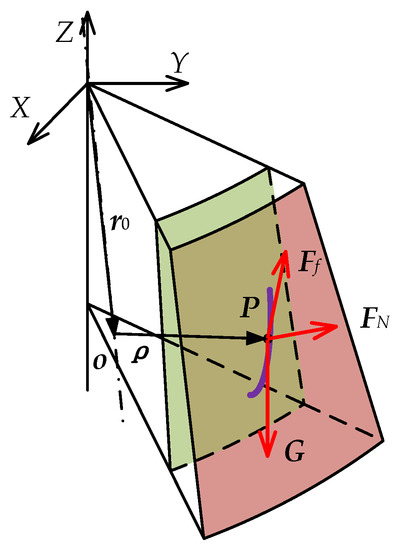
Figure 7.
The force components of spatial sliding particle.
As shown in Figure 7, the resultant force of particle P consists of three parts: the support force FN of the mantle surface, the friction force Ff between the particle and the mantle surface and the gravity G of the particle, which can be expressed by Equation (23).
The particle P is always directly contacted with the mantle surface in the spatial sliding. Therefore, the support force FN of the particle P, which is perpendicular to the mantle surface can be expressed by Equation (24).
The friction force Ff of the particle P is proportional to the support force FN, and the direction is opposite to the movement direction of particle P relative to the mantle surface, so the friction force Ff of particle P can be expressed by Equation (25).
where μ denotes the friction coefficient of particle and mantle surface.
The particle P is affected by gravity G, and the size and direction of gravity G do not change, which can be expressed by Equation (26).
where m is the weight of particle P, g denotes the gravitational acceleration.
According to the D’Alembert principle, the active force, constraint force and the inertia force acting on the particles constitute the balance force system, as shown in Equation (27). The active force is gravity G. The constraint force is the support force FN and friction force Ff of the mantle on the particle. The inertial force Fi includes Coriolis force, centrifugal force and tangential inertial force generated by the motion of mantle.
Equation (27) is decomposed along the X, Y, and Z axes of the absolute coordinate system. The balance force system in three directions of the global coordinate system can be expressed as Equations (28)–(30).
Since the particles are always in contact with the mantle surface in the spatial sliding, the path of particles must satisfy the equation of the mantle surface.
According to the coordinate system transformation matrix shown in Equations (1) and (2), the vectors and coordinates in the moving coordinate system are converted into the global coordinate system. By combining Equations (21)–(32), the equations of the spatial sliding are established. The combining equations contain not only algebraic terms, such as x, y, z and FN, but also differential terms, such as , , , , and . It contains first-order differential terms like , and , as well as second-order differential terms like , and . As a result, the combining equations of spatial sliding of particles are nonlinear second-order differential-algebraic equations (DAEs). The combining equations are solved using the Runge-Kutta method, which solves the motion characteristics of spatial sliding of particles.
3.2.2. The Motion Characteristics of Free-Falling
As the particle P is released after breaking, it is only affected by gravity G in free-falling, as shown in Figure 8. Therefore, the motion characteristics of the free-falling particle without initial velocity can be expressed by Equation (32):
where X0, Y0 and Z0 are the coordinates of the initial position of the particle in the global coordinate system.

Figure 8.
The force and acceleration components of free-falling particles.
When the particle P falls freely, it contacts the mantle surface at a certain time. Therefore, the coordinates of the contact point are determined by the free-falling time of the particle P. The contact point is the endpoint of the free-falling of the particle P and the point of the mantle surface, which can be solved by Equation (33).
According to the coordinate system transformation matrix, the coordinate equation of the contact point between the particle and the mantle surface is established. The mantle surface equation which is expressed by Equation (31) is added to solve the free-falling time of the particle, then the coordinate of the contact point is determined. Hence, the equations of the motion characteristic of free-falling are established.
3.2.3. The Motion Characteristics of Spatial Compound Falling
When the rotating speed of the main shaft is within a certain range, the gravitational acceleration of the particle is less than the acceleration of the contact point in the direction of gravitational acceleration. Although the particle can fall freely, it cannot fall freely in the whole crushing cycle. When the particle contacts the mantle surface, the particle moves with the mantle and slides along the mantle surface. Therefore, the spatial compound falling of the particle is composed of free-falling and spatial sliding. The contact point coordinates and the free-falling time can be obtained by the free-falling equation which is shown in Equations (31) and (33), then the free-falling part of the spatial compound falling of the particle can be solved. Taking the coordinates of the contact point and sliding time as the initial conditions, the spatial sliding part of the spatial compound falling of the particle can be solved based on the spatial sliding equation which is shown in Equations (15)–(31). Thus, the motion characteristics of the spatial compound falling of the particle are solved by simultaneous Equations (15)–(31) and (33).
3.2.4. The Simulation of Motion Characteristics of Particle
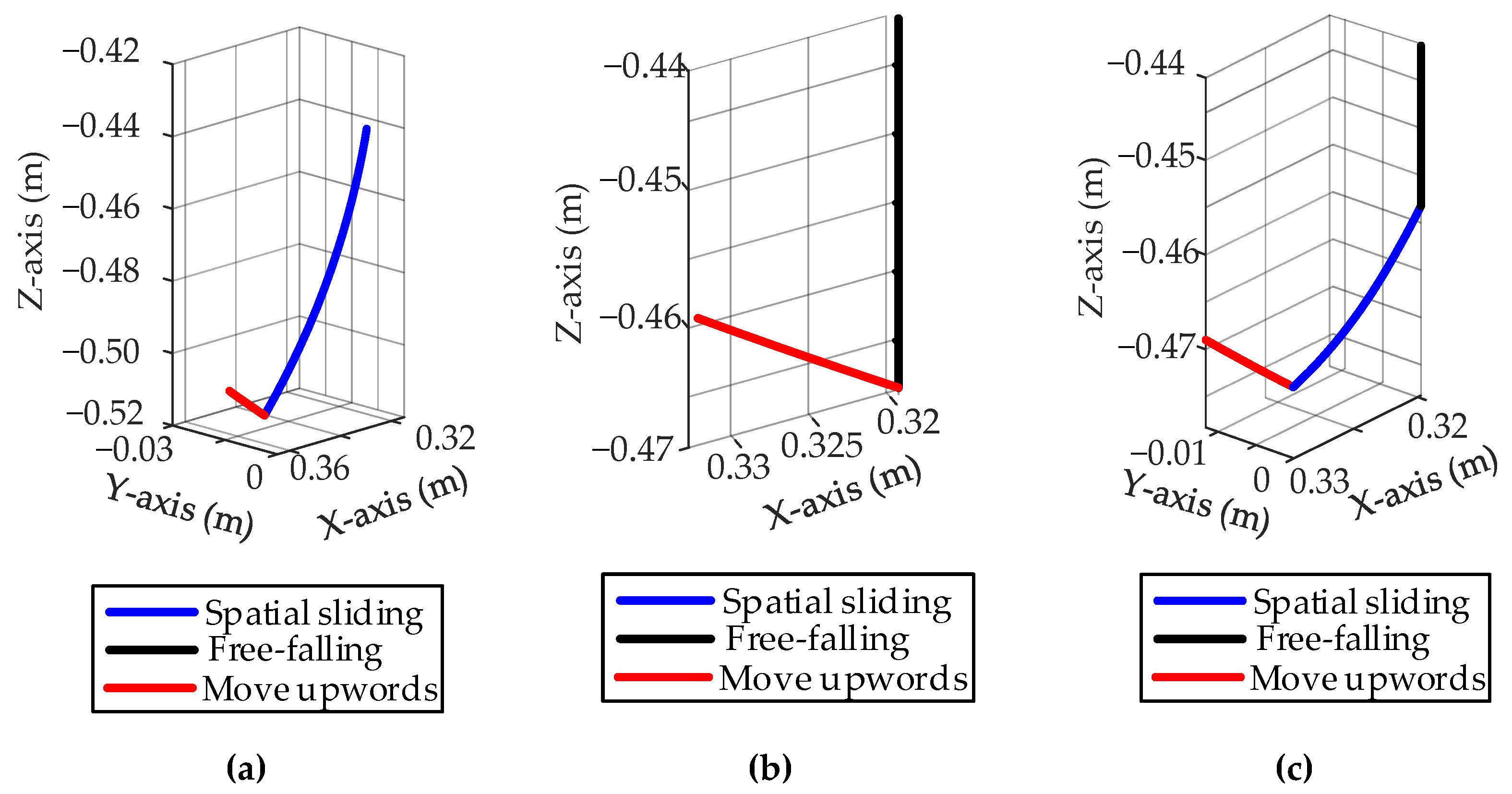
Based on the analysis of the force and acceleration of the particle in the crushing chamber, the equations of the particle with different motion characteristics are established. According to the structural and operating parameters of the cone crusher, the motion characteristic equations are solved to obtain the path of the particle in a single crushing cycle, as shown in Figure 9.
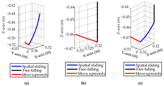
Figure 9.
The path of particle in a single crushing cycle. (a) The path of spatial sliding particle. (b) The path of free-falling particle. (c) The path of spatial compound falling particle.
As shown in Figure 9a, the motion characteristic of the particle is spatial sliding. With the decrease in height in this crushing cycle, the particle deflects circumferentially around the central axis of the cone crusher. The particles move upward with the mantle after the spatial sliding is completed. As shown in Figure 9b, the motion characteristic of the particle is free-falling. With the decrease in height, the particle does not deflect circumferentially. When a particle comes into contact with the mantle, it moves upward with it. As shown in Figure 9c, the motion characteristic of the particle is the spatial compound falling of spatial sliding and free-falling. Firstly, the particle falls freely and does not deflect circumferentially with the decrease in height. Secondly, after the contact between the particle and the mantle surface at a certain time, the motion characteristic of the particles changes to sliding falling, and the circumferential deflection occurs with the decrease in height. Finally, after the spatial compound falling is finished, the particles move upward with the mantle.
4. The Experiment of Particles Breaking in Cone Crusher
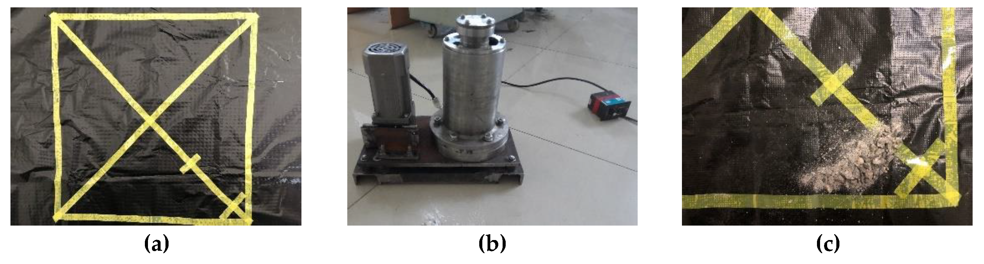
Based on the improved motion model of particles in the cone crusher considering the spatial compound motion of the mantle, the motion characteristics of particles in the crushing chamber during the dynamic crushing process are divided into spatial sliding, free-falling, and spatial compound falling. When the rotating speed of the main shaft is within a certain range, the particles deflect circumferentially around the central axis of the cone crusher. The motion characteristics of particles in the crushing chamber are simulated using a reduced-scale experimental cone crusher. The applicability and accuracy of the improved model for simulation of motion characteristics of particles in the crushing chamber during dynamic crushing are verified by comparing the measured value with the calculated value of the circumferential deflection angle of broken particles of reduced-scale experimental cone crusher with different rotating speeds of the main shaft. The experimental equipment and results are shown in Figure 10. The structural and operating parameters of the reduced-scale experimental cone crusher are shown in Table 1.

Figure 10.
The equipment and results of the experiment. (a) The circumferential coordinates systems of the working plane. (b) The reduced-scale experimental cone crusher and inverter. (c) The broken particles on the working plane.

Table 1.
The structural and operating parameters of reduced-scale experimental cone crusher.
When the motion characteristic of the particles in the dynamic crushing process is the spatial compound falling or the spatial sliding, the particles not only decrease in height but also deflect circumferentially around the central axis of the cone crusher. By adjusting the inverter, the main shaft of the reduced-scale experimental cone crusher has different rotating speeds. When the particles are fed into the crushing chamber with a fixed circumferential angle, it has various motion characteristics in the dynamic crushing process. By measuring the circumferential distribution of broken particles, the data of the reduced-scale experimental cone crusher with the different main shaft rotating speeds is obtained. Thus, the circumferential deflection of broken particles can be investigated. The experiment steps are as follows:
Step 1 The circumferential coordinates systems of the working plane of the reduced-scale experimental cone crusher are established. The circumferential position of the one-side feeding port is marked on the circumferential coordinates systems of the working plane.
Step 2 Turn on the power of the reduced-scale experimental cone crusher. By adjusting the inverter, the rotating speed of the main shaft is set to 164 rpm.
Step 3 Waiting for the reduced-scale experimental cone crusher to run smoothly. The particles with the size of 10–15 mm are selected and fed into the crushing chamber through the marked feed port.
Step 4 The crushing process of the particles in the crushing chamber is continuously observed through the cone crusher observation hole until all particles in the crushing chamber are broken and discharged from the crushing chamber.
Step 5 The reduced-scale experimental cone crusher was shut down and removed. The marked feeding port on the working plane is used as the standard point. The circumferential deflection angle of the broken particles on the working plane was measured to obtain γmax and γmin.
Step 6 Through repeated step 2 to step 5, the experiment data of circumferential deflection angles of broken particles of the reduced-scale experimental cone crusher with different main shaft speeds is obtained, as shown in Table 2.
Table 2.
The circumferential deflection angle of broken particles.
The average circumferential deflection angle is calculated according to the maximum and minimum circumferential deflection angles of broken particles in the experimental data, as shown in Equation (34):
where and are the maximum and minimum circumferential deflection angles of broken particles in the i-th experiment, n represents the total number of experiments, denotes the average circumferential deflection angle of broken particles.
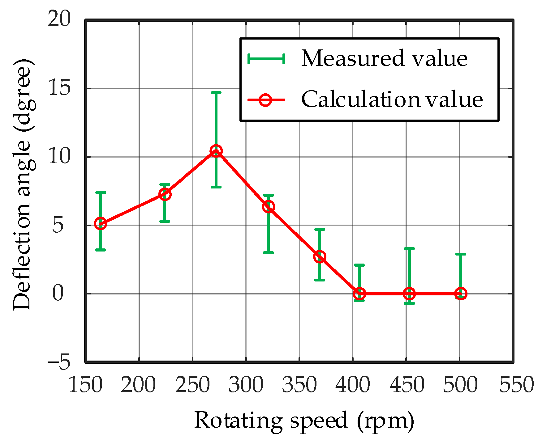
Based on the improved model, the circumferential deflection angle of the broken particles can be obtained according to the structural and operating parameters of the reduced-scale experimental cone crusher. The measured value of the circumferential deflection angle is compared to the calculated value, as shown in Figure 11.
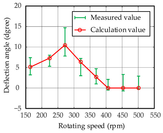
Figure 11.
The distribution of circumferential deflection angle of broken particles.
It can be observed in Figure 11 that there is a certain error between the measured and the calculation value of the average deflection angle of broken particles in the experiment. The maximum error occurs when the speed of the main shaft is 272 rpm, the positive error is 4.2°. The minimum error occurs when the speed of the main shaft is 501 rpm, the negative error is 0.3°. The error occurs because particles are fed into the one-side crushing chamber, the crushing chamber is not completely full, and the rotating speed of the main shaft is not precise enough to be adjusted through the inverter. Although the control of the experiment is not perfect and results in some errors, the variation trend of the measured values is consistent with the calculation value, and the average error between the two is 1.1°, indicating that the feasibility and effectiveness of the improved model are verified.
5. The Analysis of Particles Motion Characteristics in the CF11 Hydraulic Cone Crusher Based on the Improved Model
By analyzing the influence of the spatial compound motion of the mantle which rotates around the central axis of the cone crusher and its central axis on the motion characteristics of the particles in the crushing chamber, an improved motion model of particles considering the spatial compound motion of the mantle is established. Based on the improved model, the motion characteristics of particles in the crushing chamber can be simulated according to the structural and operating parameters of the CF11 hydraulic cone crusher, shown in Table 3.
Table 3.
The structural and operating parameters of the CF11 hydraulic cone crusher.
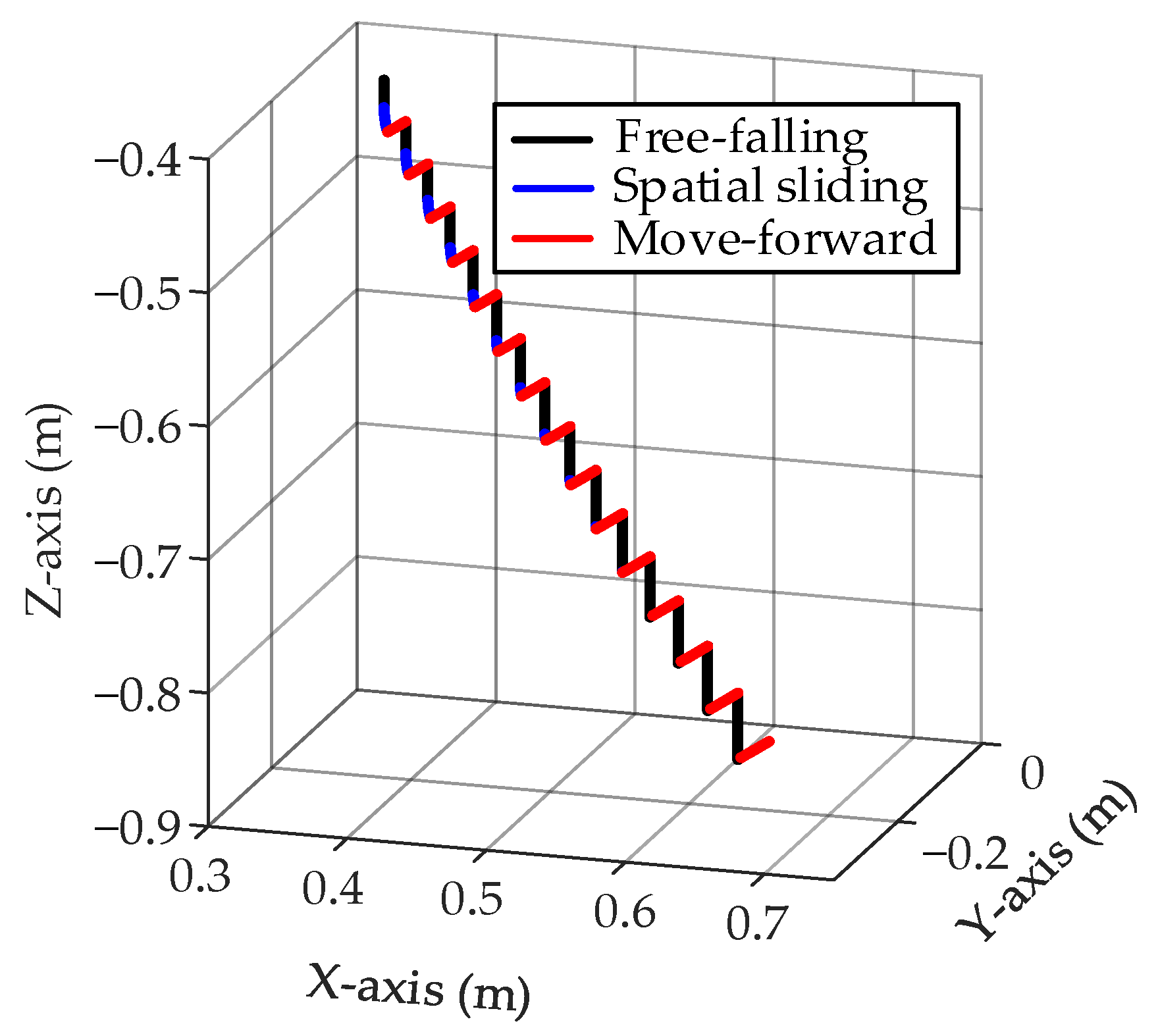
A particle in the crushing chamber of the CF11 hydraulic cone crusher was selected as the research object. Based on the improved model, according to the structural and operating parameters of the CF11 hydraulic cone crusher, the motion characteristics of a particle in the crushing chamber can be obtained. Then the path of particles in the crushing chamber can be achieved, as shown in Figure 12.
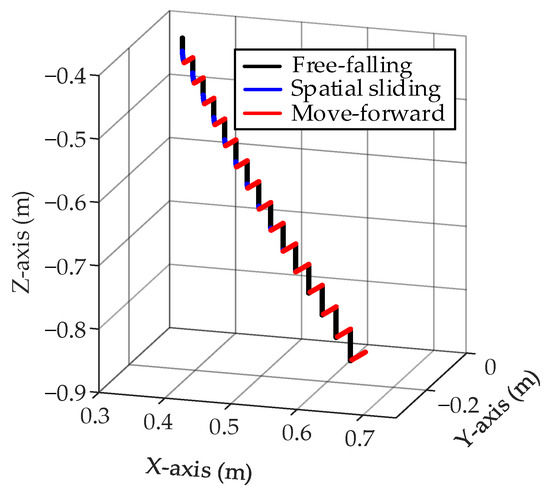
Figure 12.
The path of particles in the crushing chamber of CF11 hydraulic cone crusher.
As shown in Figure 12, the particles are discharged from the crushing chamber after 15 times of crushing. In the dynamic crushing process of particles, there are nine times of falling with the motion characteristic of the spatial compound falling and six times of falling with the motion characteristic of free-falling. The particles deflect circumferentially around the central axis of the cone crusher with the decrease in height. When the particles are discharged from the crushing chamber, the circumferential deflection angle is 4.35°.
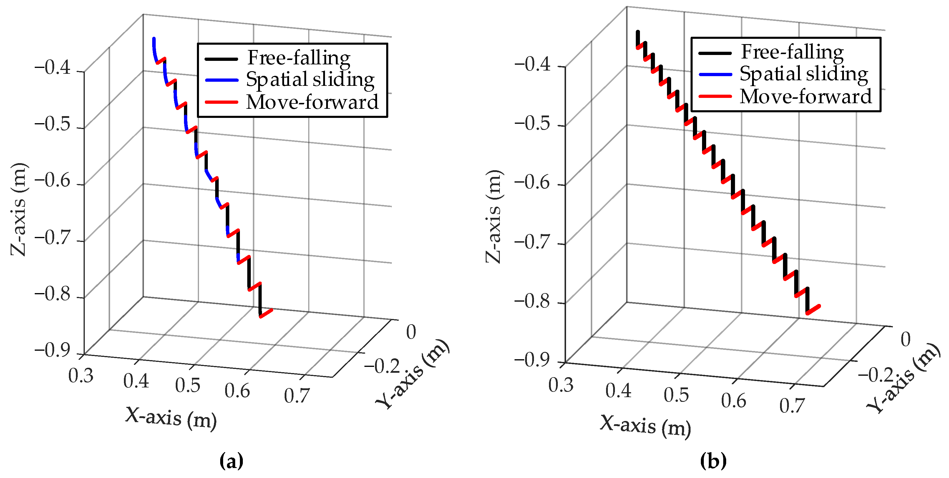
If the rotating speed of the main shaft of the cone crusher is changed, the particles in the crushing chamber will have different motion characteristics, resulting in a change in the path of the particles. If the rotating speed of the main shaft of the CF11 hydraulic cone crusher is changed to 267 rpm and 425 rpm, the path of the particles in the crushing chamber can be obtained according to the improved model, as shown in Figure 13.
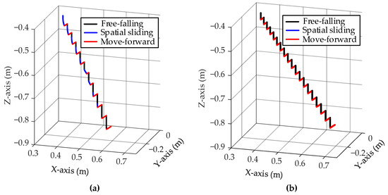
Figure 13.
The path of particles in the CF11 hydraulic cone crusher with the different rotating speed. (a) The rotating speed of main shaft is 267 rpm. (b) The rotating speed of main shaft is 425 rpm.
As shown in Figure 13, when the rotating speed of the main shaft increases from 267 rpm to 425 rpm, the number of the particle is broken increases from 11 to 19. In the dynamic crushing process of particles, the number of the spatial sliding motion characteristics decreases from 1 to 0, the number of spatial compound falling motion characteristics decreases from 8 to 1, and the number of free-falling motion characteristics increases from 2 to 18. When the rotating speed of the main shaft is 267 rpm and 317 rpm, the particles in the crushing chamber deflect circumferentially around the central axis of the cone crusher during the dynamic crushing process, and the circumferential deflection angles are 6.31° and 4.35°. When the rotating speed of the main shaft is 425 rpm, the particles in the crushing chamber do not deflect circumferentially during the dynamic crushing process. The primary reasons are as follows: As the rotating speed of the main shaft increases, the particle crushing cycle time decreases, resulting in an increase in the number of the particle is broken increases. When the rotating speed of the main shaft increases, the acceleration of the contact point on the mantle surface increases, and then the motion characteristics of the particles change from spatial sliding to spatial compound falling, and finally to free-falling, so the number of free-falling motion characteristics increases and the number of spatial sliding motion characteristics and spatial compound falling motion characteristics decreases. This results in a reduction in the circumferential deflection of the particles around the central axis of the cone crusher, thereby reducing the circumferential deflection angle.
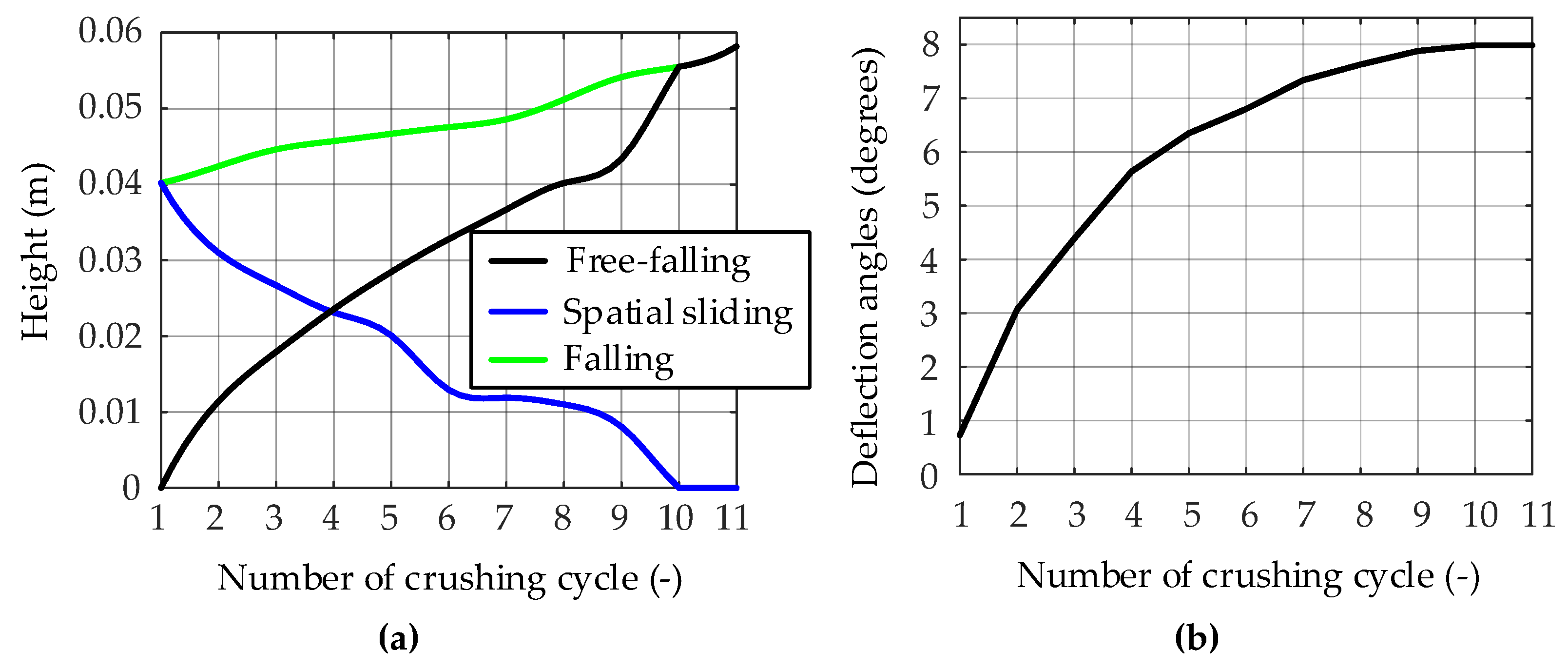
The path of the particle in the crushing chamber of the CF11 hydraulic cone crusher with the rotating speed of 267 rpm is shown in Figure 13a. The motion characteristics of the particle include spatial sliding, free-falling, and spatial compound falling. As the height of the crushing chamber decreases, the motion characteristics of the particle gradually change from spatial sliding to spatial compound falling. Finally, the motion characteristics of the particle in the bottom of the crushing chamber become free-falling. According to the study of the path of the particles in the CF11 hydraulic cone crusher with the rotating speed of 267 rpm, the height of falling, the height of free-falling, the height of spatial sliding and the circumferential deflection angles in each crushing cycle are solved, as shown in Figure 14.
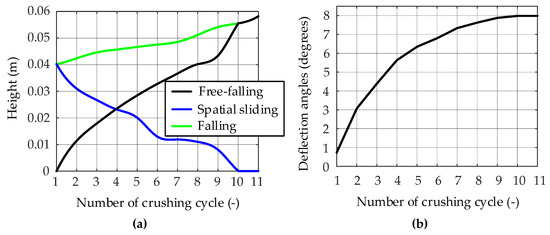
Figure 14.
The motion characteristics of broken particles in each crushing cycles. (a) The change in the height of broken particles with different motion characteristics during each crushing cycle. (b) The circumferential deflection angle of broken particles during each crushing cycle.
As shown in Figure 14a, as the number of crushing cycles increases, the height of falling and free-falling in each crushing cycle increases, and the height of spatial sliding decreases. In the 10th and 11th crushing cycles, the curve of the falling height coincides with the curve of the free-falling height. The main causes of these trends are determined by the motion characteristics of the particles. With the continuous crushing of particles, the motion characteristics of particles gradually change from spatial sliding to spatial compound falling. Additionally, the spatial sliding component of the spatial compound falling is decreasing. As a result, the height of free-falling increases and the height of spatial sliding decreases. In the 10th and 11th crushing cycles, the motion characteristics of the particles become free-falling, the height of the spatial sliding decreases to 0. Then the curves of the falling height and the free-falling height coincide. As shown in Figure 14b, the circumferential deflection angle of particles increases as the number of crushing cycles increases. However, the curvature of the circumferential deflection angle curve decreases continuously until it reaches 0 in the 10th and 11th crushing cycles. The reasons for this change are as follows: as the number of crushing cycles increases, the motion characteristics of particles are spatial sliding in the process of falling. In each spatial sliding, the particles deflect circumferentially around the central axis of the cone crusher. With the accumulation of circumferential deflection, the circumferential deflection angle of particles increases continuously. In the 10th and 11th crushing cycles, the motion characteristics of the particles become free-falling, so the particles do not deflect around the central axis of the cone crusher, then the curve has a straight-line section.
6. Discussion
The study of the spatial compound motion of the mantle reveals that it rotates both around the central axis of the cone crusher and its central axis. A coordinate system transformation matrix was established based on the structural and operational parameters of the cone crusher. Through this matrix, three typical motion characteristics of the particles directly in contact with the mantle in the dynamic crushing process are analyzed and modeled: spatial sliding, spatial compound falling and the free-falling, so the improved motion model of particles in the cone crusher considering the spatial compound motion of the mantle is established. The improved model is used to simulate the motion characteristics of particles in the crushing chamber of the reduced-scale experimental cone crusher. The accuracy and applicability of the improved model are demonstrated by comparing the measured and the calculated value of the circumferential deflection angles of the broken particles.
Based on the improved model, the dynamic crushing process of particles in the CF11 hydraulic cone crusher is simulated. The motion characteristics of particles in the crushing chamber in each crushing cycle are determined. Then, the path of broken particles is achieved. With the decrease in height, the motion characteristics of particles in the crushing chamber gradually change from spatial sliding to spatial compound falling and finally to free-falling, and the particles deflect circumferentially around the central axis of the cone crusher. By analyzing the path of particles in the CF11 hydraulic cone crusher with different rotating speeds, it was discovered that as the rotating speed increases, the main motion characteristics of particles gradually changed from spatial sliding and spatial compound falling to free-falling, and the circumferential deflection of particles gradually weakened and disappeared. Thus, the circumferential deflection of particles is directly related to their motion characteristics.
In comparison to previous research, the improved model takes into account the effect of spatial compound motion of the mantle on the motion characteristics of particles. The force and acceleration of particles are analyzed in the spatial coordinate system, and the motion characteristic of particles is solved in the global coordinate system by using a coordinate system transformation matrix. The improved model provides a more accurate method for analyzing the motion characteristics of particles in the crushing chamber, which can accurately solve the path, velocity and acceleration of particles in the dynamic crushing process. Thus, it provides a theoretical foundation for the design of high-energy crushing chambers and the optimization of crushing performance.
7. Conclusions
According to the research on the motion characteristics of particles in the dynamic crushing process are affected by the spatial compound motion of mantle rotates around the central axis of cone crushers and around its central axis, the improved motion model of particles in the cone crusher considering the spatial compound motion of the mantle was established.
Based on the research of the improved model, the particles in the crushing chamber deflect circumferentially with the decrease in height during the dynamic crushing process. The occurrence of circumferential deflection is directly related to the motion characteristics of particles. When the motion characteristic of the particles is spatial sliding or the spatial compound falling, it will deflect circumferentially around the central axis of the cone crusher. With the increase of rotating speed of the main shaft, the motion characteristics of the particles gradually change from spatial sliding to spatial compound falling, and finally, to free-falling, the circumferential deflection of the particles gradually decreases until it disappears. By investigating the particle motion characteristics in the crushing chamber, it establishes a theoretical foundation for designing high-performance cone crushers and optimizing the performance of existing cone crushers.
Author Contributions
Conceptualization, Z.Z. and T.R.; methodology, Z.Z.; validation, J.C.; formal analysis, Z.Z and J.C.; investigation, Z.Z. and J.C.; data curation, Z.Z.; writing—original draft, Z.Z.; project administration, T.R. All authors have read and agreed to the published version of the manuscript.
Funding
This work is supported by the National Key Technology R&D Program of China (grant number.2011BAF15B01).
Institutional Review Board Statement
Not applicable.
Informed Consent Statement
Not applicable.
Data Availability Statement
The data used to support the findings of this study are available from the corresponding author upon request.
Acknowledgments
The authors wish to acknowledge the JUNYANG machinery company which helped to design and manufacture the reduced-scale experimental cone rusher. The authors would especially thank all the people who help this subject, because of their aid, this topic can be successfully completed.
Conflicts of Interest
The authors declare no conflict of interest.
References
- Zhang, Z.L.; Ren, T.Z.; Cheng, J.Y.; Jin, X. The improved model of inter-particle breakage considering the transformation of particle shape for cone crusher. Miner. Eng. 2017, 112, 11–18. [Google Scholar] [CrossRef]
- Gauldie, K. The output of gyratory crushers. Engineering 1954, 4, 557–559. [Google Scholar]
- Gauldie, K. Performance of jaw crushers. Engineering 1953, 10, 456–458. [Google Scholar]
- Briggs, C.A. Fundamental Model of a Cone Crusher. Ph.D. Thesis, University of Queensland, Queensland, Australia, 1997. [Google Scholar]
- Evertsson, C.M. Output prediction of cone crushers. Miner. Eng. 1998, 11, 215–232. [Google Scholar] [CrossRef]
- Evertsson, C.M. Modelling of flow in cone crushers. Miner. Eng. 1999, 12, 1479–1499. [Google Scholar] [CrossRef]
- Pierre, J.; Yoël, F.; Olivier, P. A constitutive law for dense granular flows. Nature 2006, 441, 727–730. [Google Scholar]
- Oliver, B.; John, B.; Paul, H.; Ian, L. Flows of granular material in two-dimensional channels. J. Eng. Math. 2016, 98, 49–70. [Google Scholar]
- Cleary, P.W.; Sinnott, M.D. Simulation of particle flows and breakage in crushers using DEM: Part 1–Compression crushers. Miner. Eng. 2015, 74, 178–197. [Google Scholar] [CrossRef]
- Weerasekara, N.S.; Powell, M.S.; Cleary, P.W.; Tavares, L.M.; Evertsson, M.; Morrison, R.D.; Quist, J.; Carvalho, R.M. The contribution of DEM to the science of comminution. Powder Technol. 2013, 248, 3–24. [Google Scholar] [CrossRef]
- Cleary, P.W.; Delaney, G.W.; Sinnott, M.D.; Cummins, S.J.; Morrison, R.D. Advanced comminution modelling: Part 1–crushers. Appl. Math. Model. 2020, 88, 238–265. [Google Scholar] [CrossRef]
- Herbst, J.A.; Potapov, A.V. Making a discrete grain breakage model practical for comminution equipment performance simulation. Powder Technol. 2004, 143, 144–150. [Google Scholar] [CrossRef]
- Li, H.; McDowell, G.R.; Lowndes, I.S. A laboratory investigation and discrete element modeling of rock flow in a chute. Powder Technol. 2012, 229, 199–205. [Google Scholar] [CrossRef]
- Delaney, G.W.; Morrison, R.D.; Sinnott, M.D.; Cumminsa, S.; Cleary, P.W. DEM modelling of non-spherical particle breakage and flow in an industrial scale cone crusher. Miner. Eng. 2015, 74, 112–122. [Google Scholar] [CrossRef]
- Quist, J.; Evertsson, C.M. Cone crusher modelling and simulation using DEM. Miner. Eng. 2016, 85, 92–105. [Google Scholar] [CrossRef]
- Johansson, M.; Quist, J.; Evertsson, M.; Hulthén, E. Cone crusher performance evaluation using DEM simulations and laboratory experiments for model validation. Miner. Eng. 2017, 103, 93–101. [Google Scholar] [CrossRef]
- Meriam, J.L.; Kraige, L.G. Engineering Mechanics, Dynamics; John Wiley and Sons: New York, NY, USA, 1987; pp. 154–196. [Google Scholar]


Publisher’s Note: MDPI stays neutral with regard to jurisdictional claims in published maps and institutional affiliations. |
© 2021 by the authors. Licensee MDPI, Basel, Switzerland. This article is an open access article distributed under the terms and conditions of the Creative Commons Attribution (CC BY) license (https://creativecommons.org/licenses/by/4.0/).