Article

Surrounding Rock Stability in Unsupported Roof Area and Rapid Heading Technique for Deep Arch Coal Roadways under Goaf

1
School of Energy and Mining Engineering, China University of Mining and Technology-Beijing, Beijing 100083, China
2
School of Safety Engineering, Heilongjiang University of Science and Technology, Harbin 150022, China
3
CHN ENERGY Inner Mongolia Pingzhuang Coal Industry (Group) Co., Ltd., Chifeng 024000, China
*
Author to whom correspondence should be addressed.
Minerals 2022, 12(10), 1329; https://doi.org/10.3390/min12101329
Submission received: 28 September 2022 / Revised: 15 October 2022 / Accepted: 18 October 2022 / Published: 20 October 2022
(This article belongs to the Special Issue Green Mining of Coal Mine in China)

Abstract

:
In order to achieve rapid heading of deep arch coal roadways under goaf, the maximum unsupported roof distance (URD), surrounding rock stability of unsupported roof area and influencing factors, and rapid heading equipment and processes for these roadways are investigated in the context of the working face geology and mining conditions of Coal #9 of a certain coal mine, through theoretical analysis, numerical simulation, equipment modification, and construction process optimization. The following work is carried out: (1) Based on the thin shell theory, a mechanical model of a top cover cylindrical shell for roadways with an arch section is built. The formula for calculating the maximum URD of arch roadways is developed. The influences of roadway width, tensile strength, buried depth, and arch height on the maximum URD are analyzed. The theoretical maximum URD is worked out to be 2.4 m. (2) Numerical simulation reveals that when the URD is around 2 m, the arch roadway is free of tensile failure and the surrounding rock is well stable; when the URD is greater than 4 m, tensile failure occurs on the roadway sides, and the surrounding rock becomes less stable. Therefore, the maximum URD for numerical computation is set to 2–3 m. No additional failure occurs on the arch roof with the increase in URD, suggesting that an arch roof has the best stability. Properly increasing URD can help U-steel to gain support strength more quickly. In the shallow part of a roadway surrounding rock under goaf, failures are primarily determined by vertical stresses, whereas in the deep part, failures are determined by horizontal stresses. (3) A combined onboard standing platform + onboard beam lift device and a new onboard temporary support device for long excavation are developed as a solution to the low shed and temporary support efficiency and safety of roadways with a URD of 2.4 m and used on-site in conjunction with the optimized construction process. The result shows an average footage of over 550 m per month with a peak footage of 846.4 m and 16 supports totaling 14.1 m per shift. Additionally, the forming quality of a shed roadway is good enough to accommodate normal mining of the working face, consequently the rapid heading of the roadway.

1. Introduction

Accompanying the continuous upgrade of the full mechanization of coal mining in China is the increasing imbalance between coal mining and roadway heading. As the country’s coal mining enters a high-efficiency mining and heading phase, the efficiency of roadway heading, as a critical part of coal mining, is influencing the overall efficiency of the entire mining industry [1,2,3,4].
Coal roadway heading is a complex multistep construction process involving breaking, loading, haulage, and supporting. The speed of roadway heading is relevant not only to the modernization degree of the heading equipment, but also to the coordination among different production stages. Roadway heading has been extensively studied in and outside China with respect to heading technique, construction process and equipment, and surrounding rock control. Wang et al. [5] developed an integrated excavation and anchor concept as a means to improve roadway heading efficiency. Through numerical modeling and experiment, they discovered rules related to surrounding rock failure under high-efficiency heading and high-efficiency cutting with low specific energy consumption. Through a feasibility study of using tunnel boring machines (TBMs) in deep coal mine roadways, Cheng et al. [6] developed a TBM for deep coal mine roadways and established a quasi-static cyclic loading–unloading damage constitutive model and the nonlinear strength criterion for surrounding rock under rapid TBM construction. Du et al. [7] investigated factors influencing the roadway heading of the Linnancang coal mine from the perspectives of geological conditions, heading and support equipment, support parameters, and construction process. In order to improve roadway heading speed, Yang et al. [8] tried to support roadways with hydraulic drill rigs and managed to head the roadway safely and rapidly by optimizing the process flow and properly scheduling the construction process. In order to solve the low heading efficiency of deep soft-rock shotcrete bolt-supported roadways in the Liuquan mine, Wang et al. [9] proposed a double-wedge excavation method and a multienergy blast technique, which reduced the number of blast holes, limited the effect of blast vibration, and improved rock blasting performance. They also improved the support parameters and operation approach, which not only enhanced support strength, but also maximized the footage per cycle.
So far, fully mechanized heading is already a mature technique that is moving toward intelligence. The application of a microprocessor, computer, and expert system and the improvement of the rock stratum control theory and technology are further improving operation safety and production efficiency [10,11,12,13,14,15,16,17]. Zhang et al. [18] put forward a roadway surrounding rock classification strategy based on the self-stabilizing distance of an unsupported roof as the basic parameter to provide a basis for implementing high-efficiency heading by class and created a high-efficiency fast excavation support technique for deep mines producing 10 million tons per year in western China. Aiming at the intelligent measurement and control of heading systems, Ma et al. [19,20] created an intelligent measuring and control architecture incorporating a local control layer, a short-range central control layer, and a remote monitoring layer and proposed a digital twin-driven virtual remote intelligent control method. They developed a complete set of a shield-pushing robot system for coal roadway driving and put forward an intelligent parallel cooperative control method for a coal roadway driving robot system.
To sum up, rapid heading of coal roadways in China is developing robustly. Many impressive achievements have been made in the research of rapid heading technique and equipment and used in a number of engineering practices. However, we still lack a set of rapid heading standards specific to the practical conditions of coal mines and standard operation systems for rapid heading of real coal mine working faces. Additionally, the roof stability and instability mechanisms of unprotected roof areas are rarely reported.
In this paper, the stability of an unprotected roof area of the heading face and its influence on equipment, process, and support are analyzed by considering the complex mining geology, long advancing distance, and large roadway section of working faces in a certain coal mine. The appropriate unsupported roof distance (URD), heading equipment, and construction process are proposed. The research results are expected to provide useful clues for coal mines with similar conditions.

2. Project Overview

In the said coal mine, coal seams currently being mined include, from top down, Coal #8, #9, #11, and #12-2. Coal #8 has almost been mined up. Coal #9, the main mining seam, is relatively stable and simply structured. Standing 1.2–4.8 m thick, this seam is thin in the middle and thick on the sides, with an average coal thickness of 2.8 m. The ground elevation is +21.8 to +22.1 m with an average of +22 m. The working face elevation is −690 m. The seam dip angle is 2°–25° with an average of 18°. Currently, the mine is preparing the mining roadway for the 3098 working face. To the east of this working face is the 3094 goaf on the same coal seam and its haulage drift. To the west is Coal #9, where there is no mining and heading activity. Above are the 3086 and 3088 goafs (Coal #8 sixth and eighth working face goaf). Below, there is no mining and heading activity. Figure 1 shows the histogram of the 3098 working face. The false roof consists of 0.2 m siltstone or claystone. The immediate roof consists of 1.3 m siltstone or fine sandstone. The main roof consists of 2.5 m fine or medium coarse sandstone. The immediate floor consists of 1.6 m siltstone. The main floor consists of 3.4 m fine sandstone. Coal #9 is around 6 m away from Coal #8.
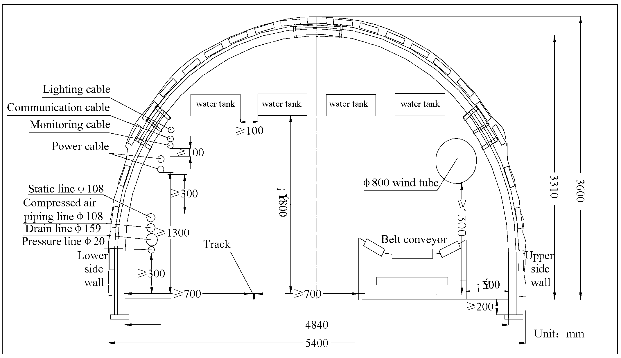
The total work quantity of the heading roadway is 3384 m, including 1052 m for the design length of the 3098 haulage way and 981 m for the design length of the 3098 airway. The roadway is supported by 29 U 14 m2 metal arch support at a shed spacing of 850 mm. The roadway is sized 5.4 m (across) by 3.6 m (high). Figure 2 shows the section layout of shed support for the 3098 haulage way and airway.
Overall, the heading faces in this mine are commonly characterized by complex geologies, such as deep burial, high ground stress, and overburden by goaf. The large heading quantity, large roadway section, and close-distance face mining have also degraded the basic physicomechanical properties of the roadway surrounding rock. These influencing factors add to the difficulty in rapid roadway forming and heading. To accommodate high-intensity, safe, and efficient mining of working faces, it is necessary to calculate the surrounding rock stability and URD of unsupported roof areas of roadways in the mine and develop an appropriate rapid heading technique.

3. Mechanical Behavior of Top Cover Cylindrical Shell Model of Unsupported Roof Area in Arch Roadway

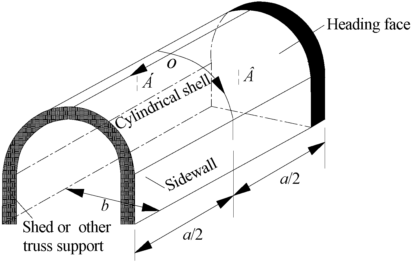
The sectional shape of the 3098 mining roadway under goaf is a three-centered arch. To facilitate computation, a cylindrical shell with a semielliptical cross section is analyzed. Assume that the width of the top cover cylindrical sell of the unsupported roof area is b and the longitudinal length is a. According to elasticity, when the side length ratio a/b of the overburden area is smaller than 0.5, the moment free theory can apply; when this ratio is between 0.5 and 1.5, namely, for a top cover cylindrical shell with an overburden area approximating a square, the displacement and internal force should be calculated by trigonometric series; when this ratio is 1.5 ≤ a/b ≤ 3.0, the semimoment free theory must apply to the top cover cylindrical shell; when this ratio is larger than 3.0, the beam theory would be preferable. For a deep coal roadway, where the top cover side length ratio in the unsupported roof area is smaller than 0.5, the moment free theory is generally sufficient.

3.1. Moment Free Theory of Cylindrical Shell

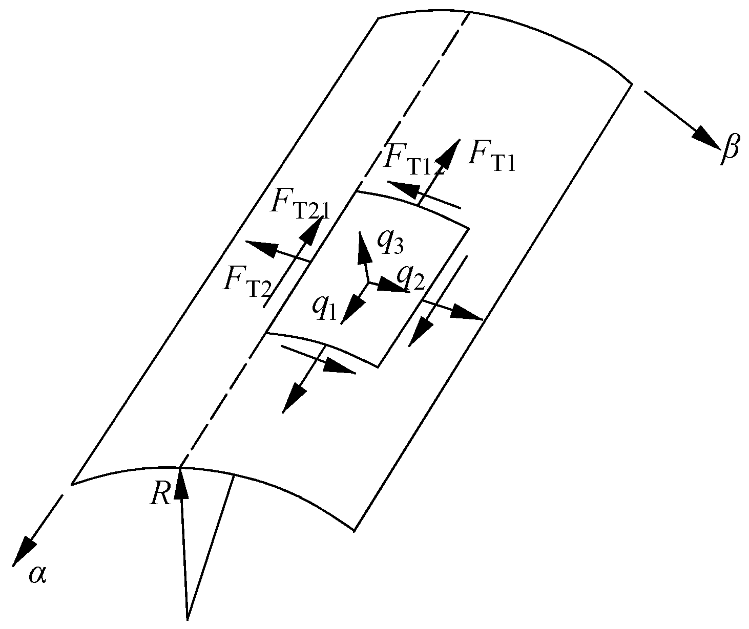
An arch coal mine roadway can be seen as a thin shell with a cylinder as the middle surface, called a cylindrical thin shell or cylindrical shell. For a cylindrical shell, it is a general practice to place the α coordinate in the longitudinal direction, that is, the direction of the generatrix of the cylinder, and the β coordinate in the circumferential direction, that is, the directrix of the cylinder, as shown in Figure 3. The moment free theory assumes that all cross sections of the shell are free of any bending or torsion moment. Using the moment free hypothesis, the moment free theory equilibrium equation of a general thin shell can be further simplified to derive the moment free theory equilibrium equation of cylindrical shell as [21]:
F T 1 α + F T 12 β + q 1 = 0 F T 2 β + F T 21 α + q 2 = 0 F T 2 = R q 3
During calculation, we can first derive the circumferential tensile pressure FT2 from the third equation of the equilibrium Equation (1), then substitute it into the second equation and integrate α to derive the level dislocation force FT12, then substitute FT2 into the first equation and integrate α to derive the longitudinal tensile pressure FT1. In some cases, any function appearing during integration can be derived from the boundary conditions of internal force.

3.2. Moment Free Calculation of Top Cover Cylindrical Shell

The roadway arch roof is seen as a cylindrical shell for the top cover, as shown in Figure 4, with its ends supported on continuous walls. The stiffness of the sidewall is very large within its plane but is very small in the direction perpendicular to its plane. The linear boundaries of the cylindrical shell are rigidly connected to the two roadway sides. Hence, we can assume that the cylindrical shell is not subject to longitudinal tensile pressure on the curved boundaries at the ends. Then the boundary conditions can be expressed by the coordinate system shown in the diagram as:
F T 1 α = ± a / 2 = 0 F T 12 α = a / 2 = F T 21 α = a / 2 = 0
The loads on the top cover cylindrical shell are primarily vertical ones. Suppose the vertical load on the cylindrical shell per unit of area is q0, then we have:
q1 = 0, q2 = q0sinφ, q3 = −q0cosφ
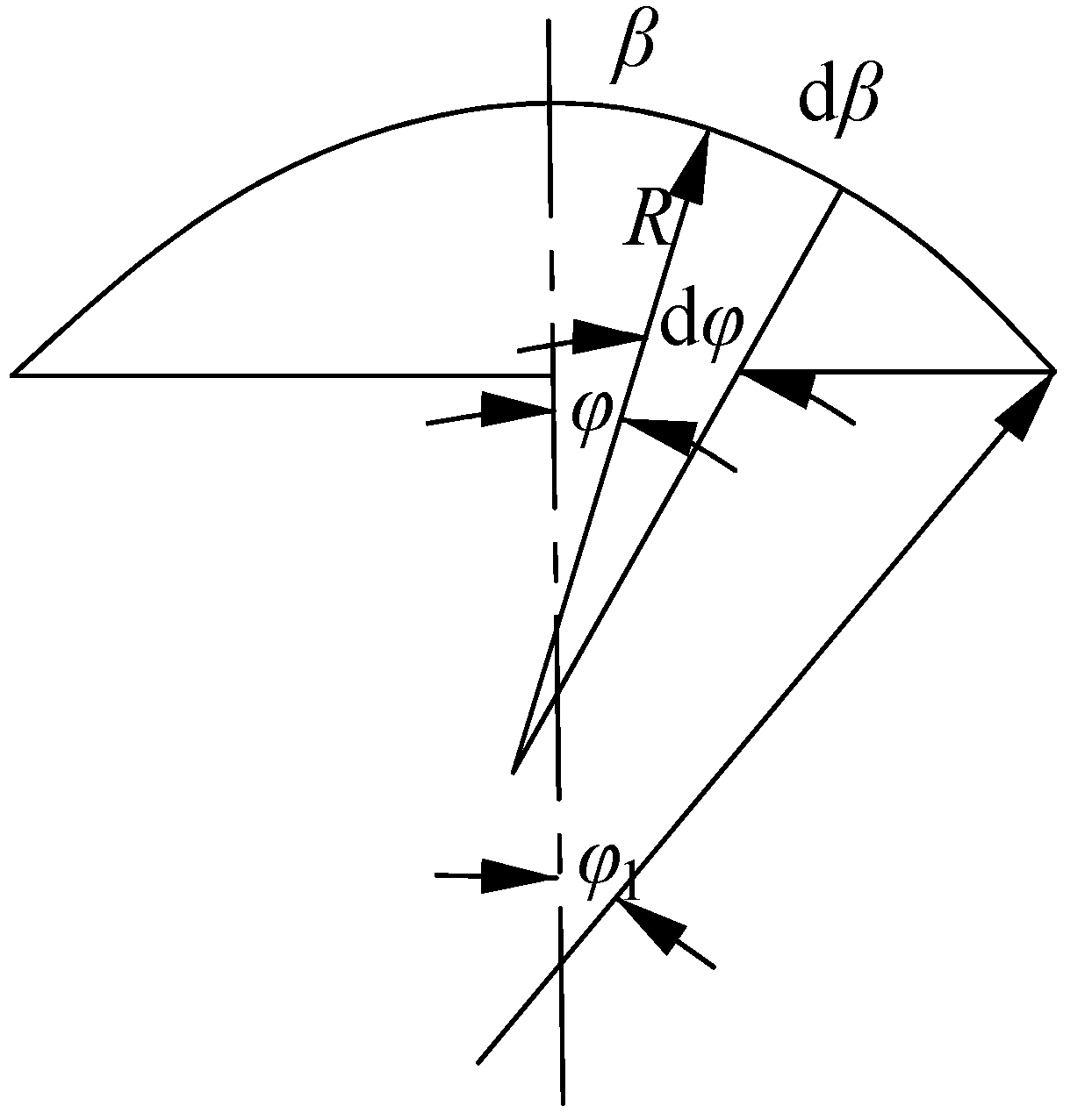
where φ is the angle between the normal of the middle surface of the cylindrical shell and the plumb line, as shown in Figure 5. To facilitate computation, we use angle φ as the circumferential coordinate instead of β hereinafter. Using Equation (3) and geometric relation dβ = Rdφ, the equilibrium Equation (1) can be rewritten as:
F T 1 α + 1 R F T 12 φ = 0 F T 12 α + 1 R F T 2 φ + q 0 sin φ = 0
F T 2 = q 0 R cos φ
Substituting Equation (5) into the second equation of Equation (4)—note that R is also a function of φ—yields:
F T 12 α = q 0 sin φ 1 R F T 2 φ = q 0 R d R d φ cos φ 2 q 0 sin φ
By integrating and using boundary condition (2), we have:
F T 12 = q 0 1 R d R d φ cos φ 2 sin φ α a 2
Substituting it into the first equation of Equation (4) yields:
F T 1 α = 1 R F T 12 φ = q 0 α a 2 R φ 1 R d R d φ cos φ 2 sin φ
By integrating a and using boundary condition (2), we have:
F T 1 = q 0 2 R α 2 + a α + a 2 4 φ 1 R d R d φ cos φ 2 sin φ
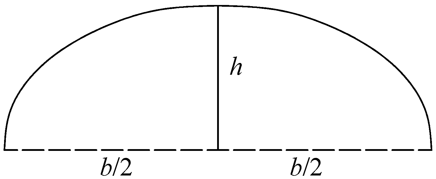
For a cylindrical shell of any shape, the moment free internal force can be derived from Equations (5), (7) and (9). The cross section of the cylindrical shell is approximately seen as semielliptical, as shown in Figure 6. Its radius of curvature is:
R = h 2 b 2 1 ε 2 cos 2 φ 3 / 2
where φ is the angle between the normal and minor axis of the ellipse, namely, the angle between the tangent and major axis of the ellipse; ε is the eccentricity of the ellipse; and ε 2 = 1 h 2 / b / 2 2 . Substituting all three into Equations (5), (7) and (9), we have the expression of internal force as:
F T 2 = q 0 b 2 2 h 2   cos φ b 2 2 sin 2 φ   +   h 2 cos 2 φ 3 / 2 F T 12 = q 0 α     a 2 2 b 2 2   +   b 2 2     h 2 cos 2 φ b 2 2 sin 2 φ   +   h 2 cos 2 φ sin φ F T 1 = q 0 b a 2   +   4 a α   +   4 α 2 1     ε 2 cos 2 φ 3 / 2 8 h 2 3 ε 2 cos 2 φ 1     ε 2 cos 2 φ   +   3 2 ε 4 sin 2 2 φ 1     ε 2 cos 2 φ 2 2 cos φ
Among these stresses, tensile stress FT1 plays a decisive role in the failure of the thin shell. From Equation (11), the tensile stress maximizes when α = a/2, that is, at the point where the unsupported roof area is farthest from the heading face. Substituting it into Equation (11) yields the maximum tensile stress FT1max as:
F T 1 max = a 2 q 0 b 1     ε 2 cos 2 φ 3 / 2 2 h 2 3 ε 2 cos 2 φ 1     ε 2 cos 2 φ   +   3 2 ε 4 sin 2 2 φ 1     ε 2 cos 2 φ 2 2 cos φ
If the ultimate tensile strength of the roof is [σt], then the roof is safe when FT1maxσt. Thus, the roof is self-stabilized when:
F T 1 max σ t 0
From Equations (12) and (13), we can derive the maximum URD of an arch roof as:
a = 2 h 2 σ t 3 ε 2 cos 2 φ 1     ε 2 cos 2 φ     3 2 ε 4 sin 2 2 φ 1     ε 2 cos 2 φ 2   +   2 cos φ q 0 b 1     ε 2 cos 2 φ 3 / 2
From this equation, the roof stability in the unsupported roof area is relevant to roadway width, arch height, tensile strength, and roof load.

3.3. URD Calculation for Semicircular Arch Roadway

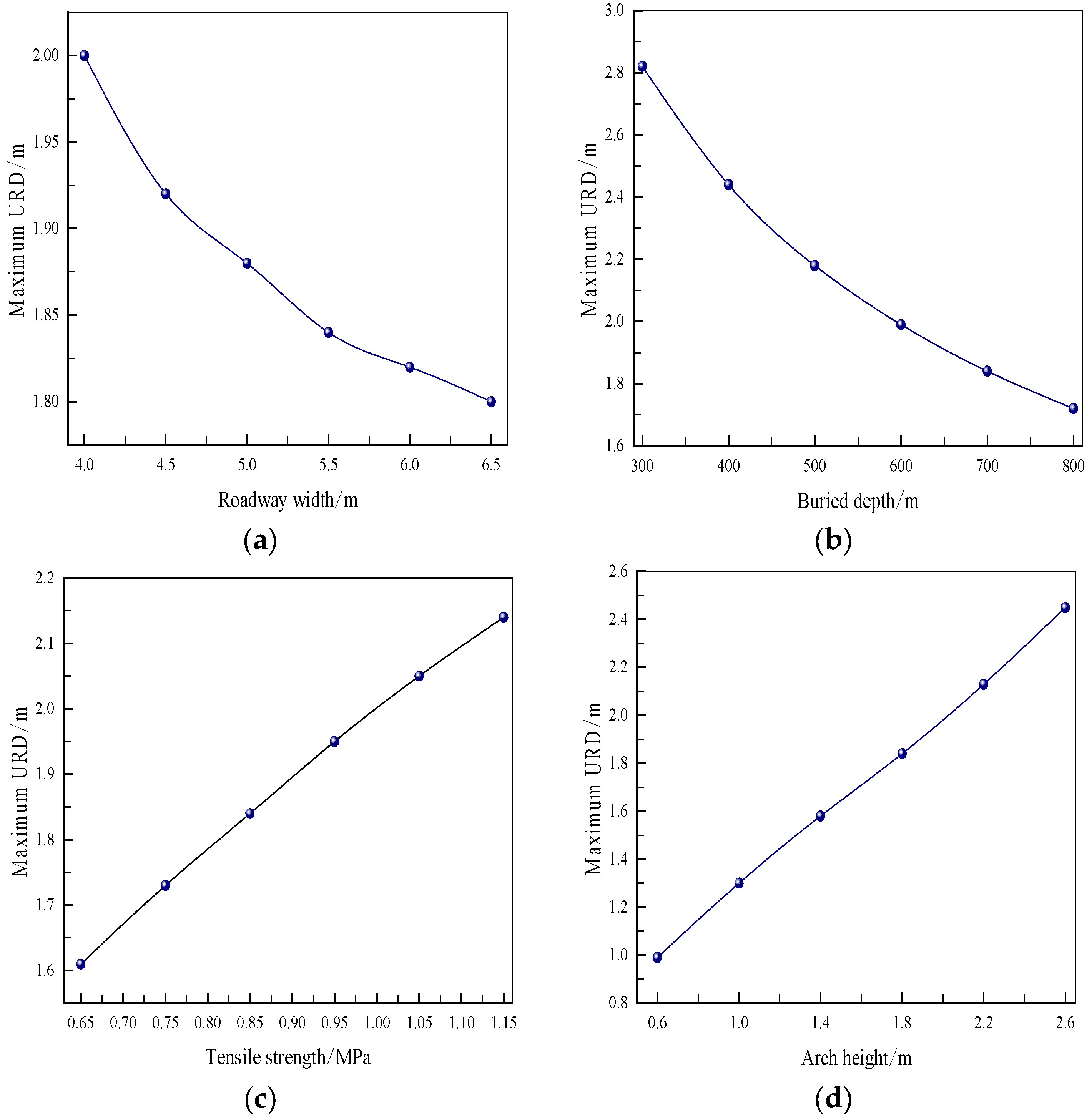
To find out under what conditions an arch roof fractures, calculation was performed using the following parameters: roof tensile strength: 0.65, 0.75, 0.85, 0.95, 1.05, and 1.15 MPa; roadway width: 4.0, 4.5, 5.0, 5.5, 6.0, and 6.5 m; buried depth: 300, 400, 500, 600, 700, and 800 m; arch height: 0.6, 1.0, 1.4, 1.8, 2.2, and 2.6 m. These parameters were substituted into Equation (14) by a control variable method to derive a, the maximum URD.
The above influencing factors were calculated according to Equation (14). When one factor was chosen as the variable, the other parameters were controlled as the actual roof reference geological and technical condition parameters for the 3098 haulage chute, namely, b = 5.5 m, H = 700 m, σt = 0.85 MPa, h = 1.8 m. Table 1 gives the calculation result.
With the data in this table, maximum URD curves were plotted for different influencing factors, as shown in Figure 7.
The graphs in Figure 7 were analyzed with the data in Table 1. From Figure 7a, the maximum URD tends to reduce with increasing roadway width, suggesting that a larger section width corresponds to a poorer surrounding rock stability. For roadways with a large section, the maximum URD has to be controlled to an acceptable limit. To achieve rapid heading, the section width should be minimized to the extent of allowing adequate haulage ventilation. Compared with the said thin-shell roof, the maximum URD reduces with roadway width at a smaller rate, suggesting that an arch roadway is more stable and an arch section is good for increasing URD.
In Figure 7b, the maximum URD tends to reduce with increasing buried depth. However, compared with the linear reduction of the maximum URD for a thin-shell roof, after the burial depth has increased beyond 500 m, the maximum URD of an arch roof begins to reduce at a smaller rate. Therefore, an arch roof should be more applicable for deep roadways.
In Figure 7c, the maximum URD tends to increase linearly with increasing tensile strength. In Figure 7d, the maximum URD tends to increase linearly with increasing arch height. These suggest that the surrounding rock is more stable when the roof is more circular or when the arch roof takes a larger weight of the roadway section area.
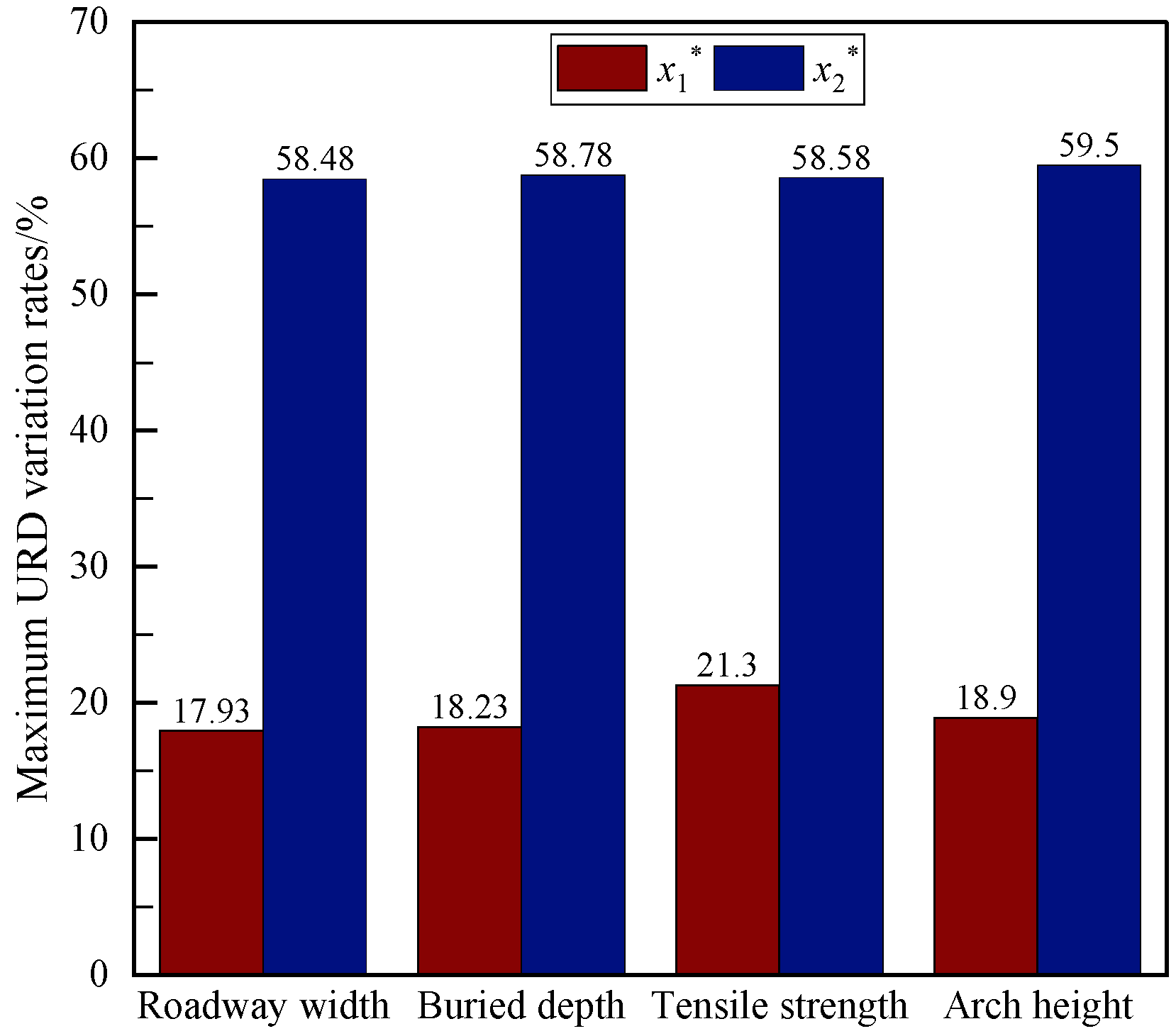
To examine the contributions of the influencing factors to URD more closely, it is necessary to normalize the above data. By substituting the data in Table 1 into the min–max normalization Formula (15) and the Z-score normalization Formula (16), maximum URD variation rates under different influencing factors can be obtained. These variation rates can reflect the contributions of individual influencing factors to the maximum URD. Figure 8 compares maximum URD variation rates under different influencing factors.
x 1 = x min max min
where max is the maximum of the sample data, and min is the minimum of the sample data. One shortcoming of this method is that max and min could be changed when new data are added and have to be redefined:
x 2 = x μ σ
where μ is the mean of all sample data, and σ is the standard deviation of all sample data.
From the diagram in Figure 8, maximum URD variation rates under individual influencing factors differ largely between two normalization methods, but do not differ much within the same method. By min–max normalization, the roof maximum URD is sensitive to tensile strength (21.3%) > arch height (18.9%) > buried depth (18.23%) > roadway width (17.93%); by Z-score normalization, the roof maximum URD is sensitive to arch height (59.5%) > buried depth (58.78%) > tensile strength (58.58%) > roadway width (58.48%). Except for one single indicator, tensile strength, the overall variation is much the same. It therefore can be assumed that the four factors influence the roof maximum URD in basically the same way.
Further analysis of the above data can lead to the following conclusions:
(1)
The maximum URD for heading arch roadways is closely related to the roof rock tensile strength, roadway arch height, roadway width, and roof load, each of which has roughly the same degree of influence, suggesting that an arch roadway is well stable and highly adaptable to varying geological conditions.
(2)
The URD of arch roadways is insignificantly sensitive to roadway width. Therefore, an arch section is more beneficial to roadways with a large section.
(3)
Arch height has a great influence on the URD of arch roadways, so a large arch height would be recommendable in practical engineering design. Tensile strength also has a great influence on the URD of arch roadways, so in cases of degraded roof tensile strength, a small URD would be more preferable.
Based on the above analysis and calculation, the theoretical maximum URD for the arch roadway of the 3098 heading face on Coal #9 was determined to be 1.84 m. As this thin shell theoretical calculation agrees with the real project, plus the thin shell is insignificantly sensitive to geological factors, the safety factor can be ignored in real application. That is, the real maximum URD is also 1.84 m. Moreover, as the roadway section of the mine is a three-centered arch, whose curvature, consequently the maximum URD, is larger than an elliptical section, at a safety factor of 1.3, the maximum URD of a roof with a three-centered arch section is 2.4 m.

4. Numerical Simulation of Arch Roadway under Goaf

This section may be divided by subheadings. It should provide a concise and precise description of the experimental results, their interpretation, and the experimental conclusions that can be drawn.

4.1. Model Building

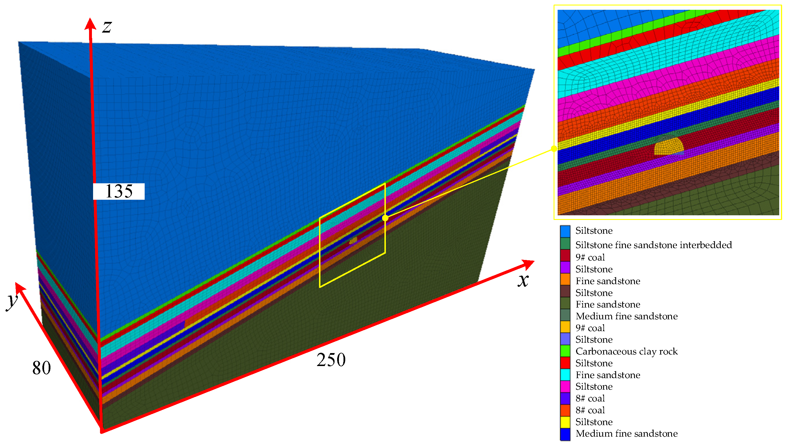
As the average dip angle of the seam is approximately 18°, this would in a way affect roadway heading. Considering the potential influence of boundary constraints on the computational results, the model was sized L × W × H = 250 m × 80 m ×135 m, as shown in Figure 9. Considering the operation speed and calculation accuracy, the roof and floor meshes near the roadway were moderately refined. A total of 992,979 nodes and 968,080 elements were deployed. The rock stratum meshes near the seam were moderately refined and sized X × Y × Z = 0.4 m × 1.0 m × 0.4 m. The rock stratum meshes in the remaining roof and floor areas were larger and sized X × Y × Z = 1.6 m × 1.0 m × 1.6 m. The roadway was sized 5.4 m × 3.6 m and was headed along the coal floor.
During simulation, the Mohr–Coulomb criterion was used for calculation. Table 2 gives the physicomechanical parameters of the coal strata. The top boundary of the model was stress-constrained, and stress was used as an equivalent to buried depth. To the top of the model, 17.75 MPa vertical stress was applied, equivalent to the weight of a 710 m thick overburden. The horizontal stress was 14.62 MPa for sxx and 10.23 MPa for syy. The model was constrained by normal displacement on the left, right, front, and rear boundaries, and by normal and tangential displacement on the bottom boundary.
As Coal #9 is overburdened by the goaf of Coal #8, Coal # 8 is excavated before the chute of the 3098 working face. U-steel shed support is used. In the model, the U-steel compressive support was simulated with beam elements. The normal and tangential stiffness of the contact elements were determined by referring to the FLAC3D5.0 User Manuals. According to the material properties f U29 steel, the following parameters were determined: yield strength = 400 MPa, bending section modulus = 100 cm2, elastic modulus = 210 GPa, xciz = 9.29 × 10⁻⁶, xciy = 12.45 × 10⁻⁶, xcj = 0, yield bending moment = 45,600 N·m, and Poisson ratio = 0.2.

4.2. Influence of URD on Roadway Surrounding Rock Stability in Unsupported Roof Area

Five URDs were designed: 2, 4, 6, 8, and 10 m. The roadway excavation length was 40 m.
Figure 10a–e compares the roadway surrounding rock plastic zone distributions in different unsupported roof areas, obtained by transversely slicing the middle part of these areas. When the URD is 2 m, roadway surrounding rock failures are primarily shear type. Small tensile failure occurs only on the floor and sides. The roadway stability is the best at this time. When the URD is 4 m, large tensile failure zones appear on the roadway sides. The failure depth is 1.2 m. The tensile failure on the floor is enlarged too. When the URD is increased to 6–10 m, the tensile failure on the right side continues to deepen, peaking to 2.0 m at a URD of 10 m; a large shear failure zone appears deep in the surrounding rock on the left side, degrading the surrounding rock stability on the roadway sides. Therefore, for a broken soft rock roadway under goaf, a maximum URD of around 2 m can ensure roadway stability and safe rapid heading. It is also noted that no tensile failure will occur to the arch roof of an arch roadway at all. Any new shear failure is small in size too. An arch roof has high bearing capacity and good stability. Therefore, for broken soft rock roadways under goaf, an arch section should be a prerequisite for rapid heading.

4.3. Influence of URD on U-Steel Shed Support

U-steel shed support is a passive support. In real application, where the interaction between the support and the surrounding rock is weak, the actual bearing capacity of the support is only 1/3–1/5 of the theoretical value or even lower. Although backwall infilling has greatly improved the bearing capacity and support resistance of U-steel support, the working resistance can be effectively increased only when roadway surrounding rock deformation leads to an increase in the load on the support and the support is compressed. Figure 11(a-1)–(a-5) compares the axial stress distributions of a U-steel section under different URDs. Figure 11(b-1)–(b-5) compares the vertical displacement distributions of a U-steel under different URDs. From these nephograms, the nearer the U-steel to the heading face, the smaller the axial stress and vertical displacement. Especially for the four U-steels nearest to the heading face, the displacement is negative and the beam top is virtually unstressed. On the contrary, for roadways farther away from the heading face, as they were excavated long ago, they are more badly displaced and deformed. Consequently, the axial stress and vertical displacement of a U-steel section are larger. It is also noted that the larger the URD, the larger the vertical displacement enlargement of the shed leg, which is more prominent when the URD is larger than 4 m.
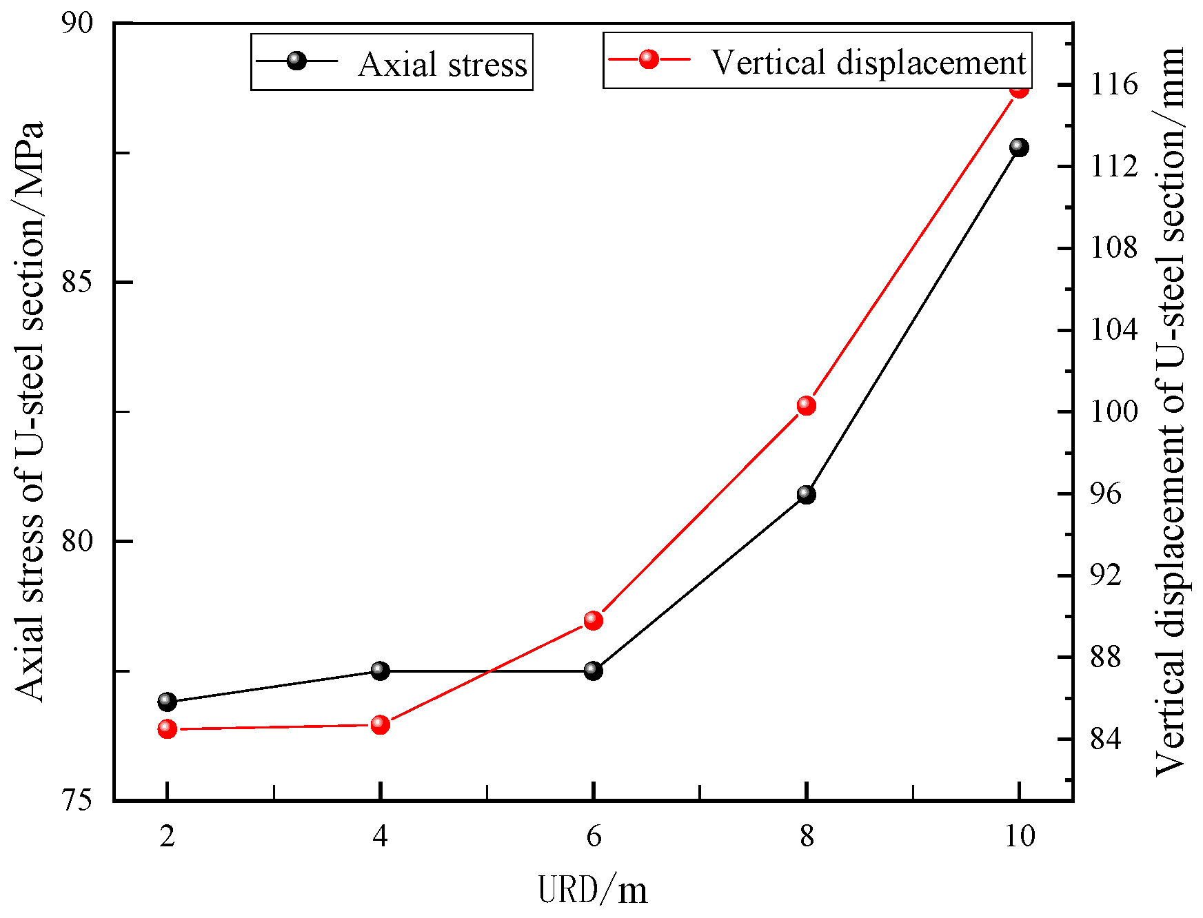
Figure 12 further compares these differences. The axial stress of a U-steel increases linearly with increasing vertical displacement. As URD increases, vertical displacement increases by 37% from 84.5 to 115.8 mm; axial stress increases by 14% from 76.9 to 87.6 MPa. Obviously, roadway deformation acts on the U-steel and causes its support strength to increase.
To sum up, the support begins to bear load when the roadway surrounding rock is deformed to a given extent. In a broken soft rock roadway, the support resistance provided by U-steel shed support for the surrounding rock is very small in the beginning. However, as the surrounding rock deformation increases, the bearing capacity of the U-steel shed is increased rapidly. Therefore, properly increasing URD can help the U-steel to gain support strength quickly. In real roadway support, a three-centered arch roadway should be strictly sized and the back plate should be well inserted to keep the roadway support in uniform contact with the roadway surrounding rock and avoid leaving the roof unsupported.

4.4. Influence of Maximum Horizontal Stress on Roadway Surrounding Rock Stability in Unsupported Roof Area

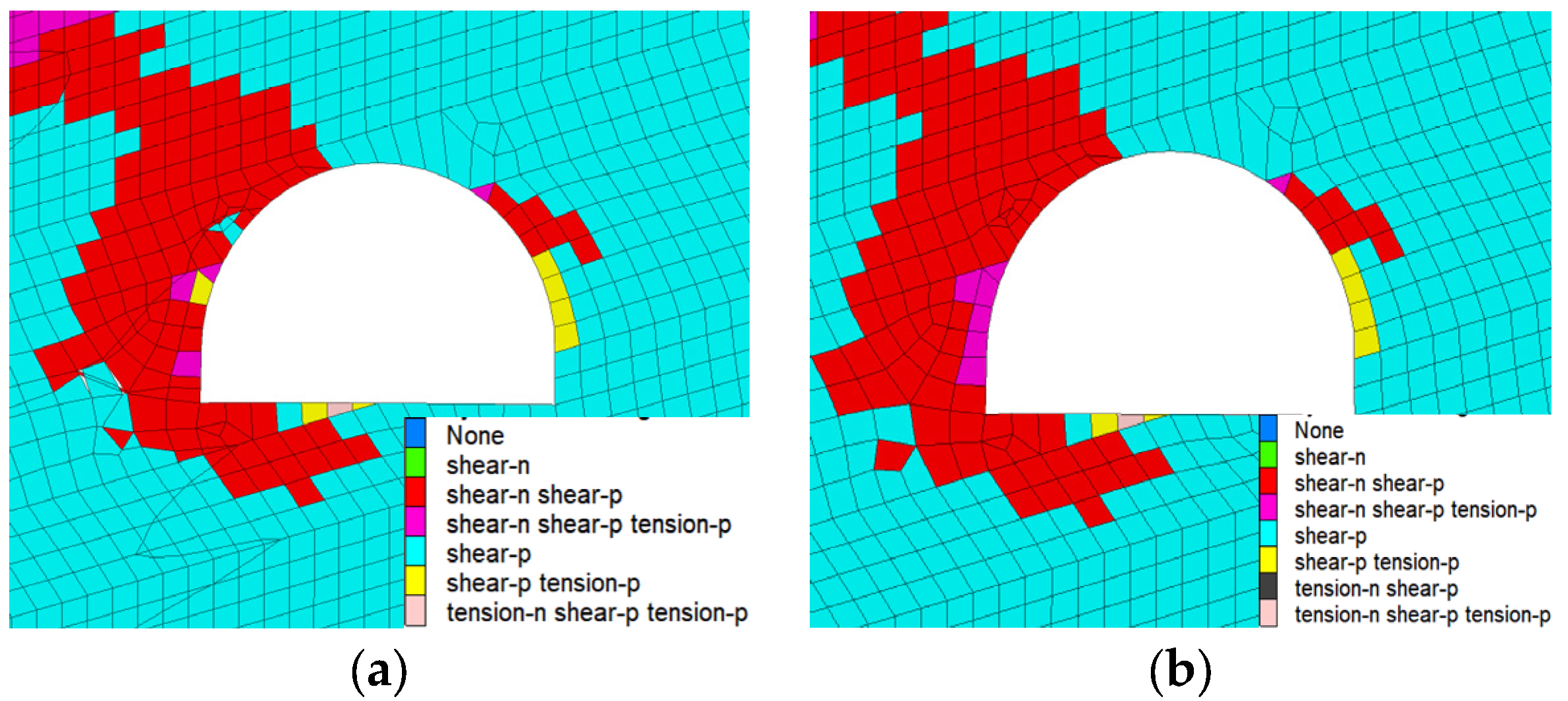
Figure 13 compares the development of a roadway surrounding rock plastic zone when the design maximum horizontal stress is vertical and horizontal relative to the roadway. The failure type, depth, and scope of the plastic zone remain basically unchanged, suggesting that the angle between maximum horizontal stress and the roadway affects the surrounding rock stability of roadways under goaf very insignificantly.
However, maximum horizontal stress determines the form of a surrounding rock failure. As can be seen from Figure 13 above, recurring surrounding rock failures are obviously asymmetric; failures on the left side are far larger than on the right side; the failure depth extends all the way from the top to the inside of the left side. Taking into account the roadway stress distributions in Figure 14, it can be seen that in the shallow part of the roadway surrounding rock, failures are primarily determined by vertical stresses, whereas in the deep part, as further failure will occur at locations where horizontal stresses are concentrated, failures are primarily determined by horizontal stresses. The location where horizontal stresses are concentrated, which is jointly determined by the dip direction of the coal seam and the spatial position of the roadway relative to the goaf, generally lies between the roadway and the goaf, at a point closer to the lower part of the coal seam.
By combining the theoretical analysis and numerical simulation results, it is assumed that a maximum URD of 2.4 m can both ensure roadway surrounding rock stability and bring the U-steel shed to its play quickly.

5. Design and Performance of Modified Rapid Heading Equipment

In view of the particular mining conditions of the mine and the expectation to achieve a maximum URD of 2.4 m, traditional heading equipment would face the following challenges:
(1)
The roadway is supported by shed support, and it has a large section. U-steel support is both large and heavy. When installing shed support, temporary scaffolds have to be put up, and a back plate has to be inserted in advance. This requires a lot of labor and time. Manual shed installation is time and labor consuming. The safety factor and cycle efficiency are both low.
(2)
The temporary support devices for traditional roadheaders are generally suitable for flat-roofed and immediately supported roadways or those permanently supported by rock bolts. For shed roadways, as effective temporary support is not available when installing shed support, the workers usually have to operate under an exposed roof, and the safety factor is very low. To ensure safety, the maximum URD of the roadway has to be limited to a small value. Therefore, the heading efficiency is very low.
To solve these problems, a modified rapid heading device was designed.

5.1. Combined Onboard Standing Platform + Onboard Beam Lift Device

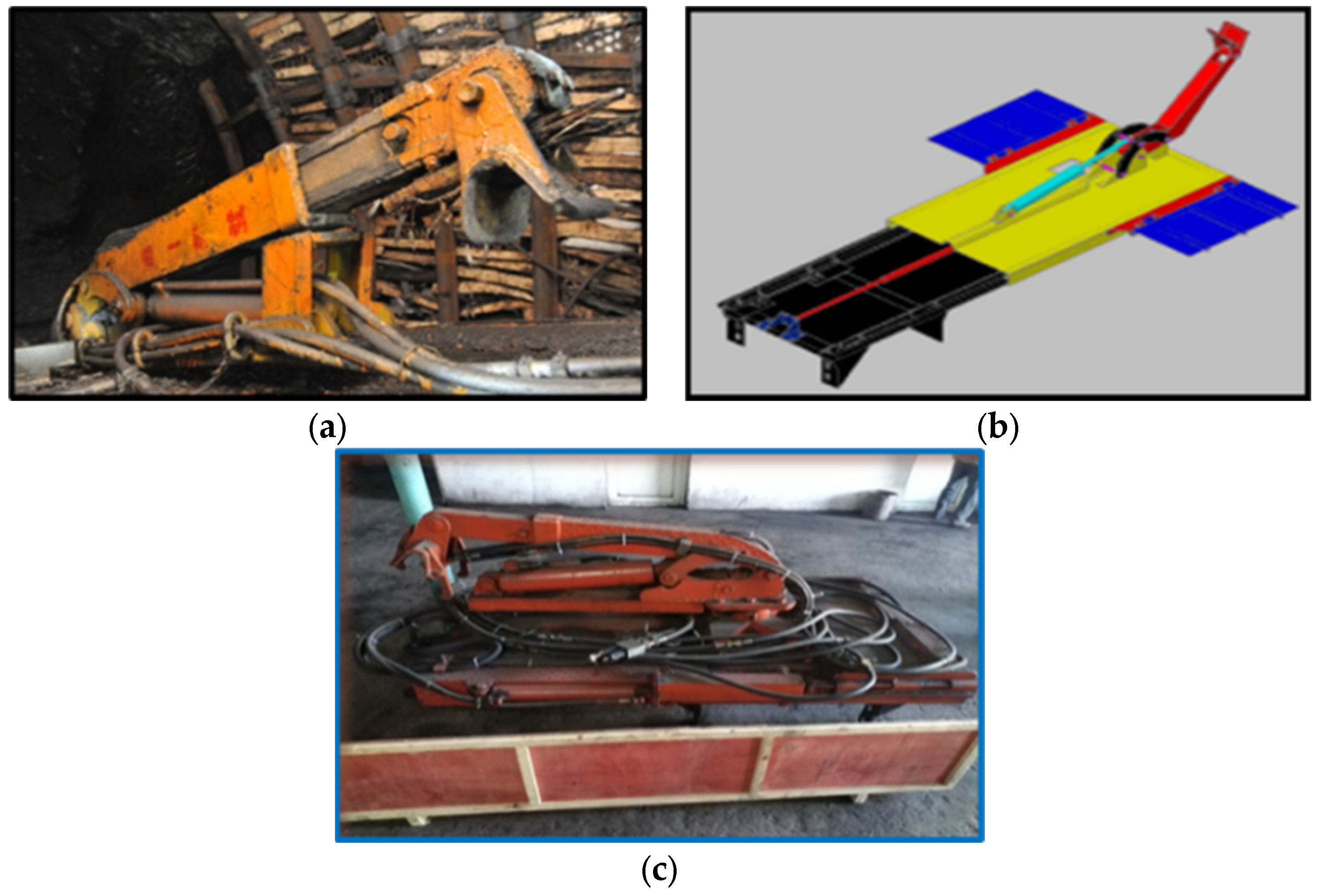
When traditional shed support is installed, temporary scaffolds have to be put up and a back plate has to be inserted in advance. This requires a lot of labor and time. The safety factor and cycle efficiency are both low too. To solve these problems, a combined onboard standing platform + onboard beam lift device was designed. Table 3 gives the development and application history of this device.
Figure 15 shows our combined onboard standing platform + onboard beam lift device. The use of this device directly saves the step and time of putting up temporary scaffolds. With this device, the worker can install support from the onboard standing platform; the onboard beam lift will lift the beam instead of a worker such that before the beam is lifted, the back plate is inserted and lifted together with the support. This saves the time needed for inserting the back plate and reduces human labor too.

5.2. New Onboard Temporary Support Device for Long Excavation

Temporary support for the heading face of fully mechanized heading roadways is a tough, complex, and low-efficiency task, because the fully mechanized roadheader and the support bolting operate separately, wasting a lot of time.
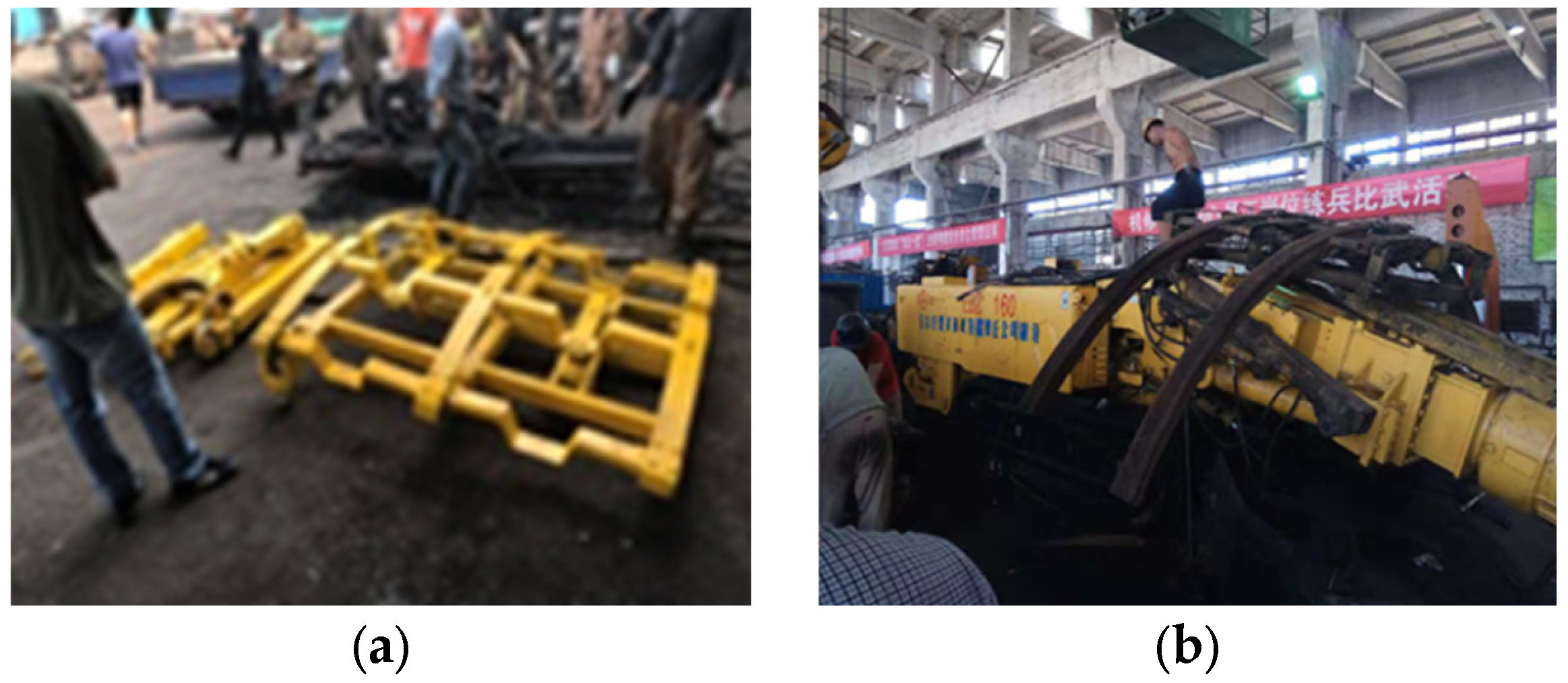
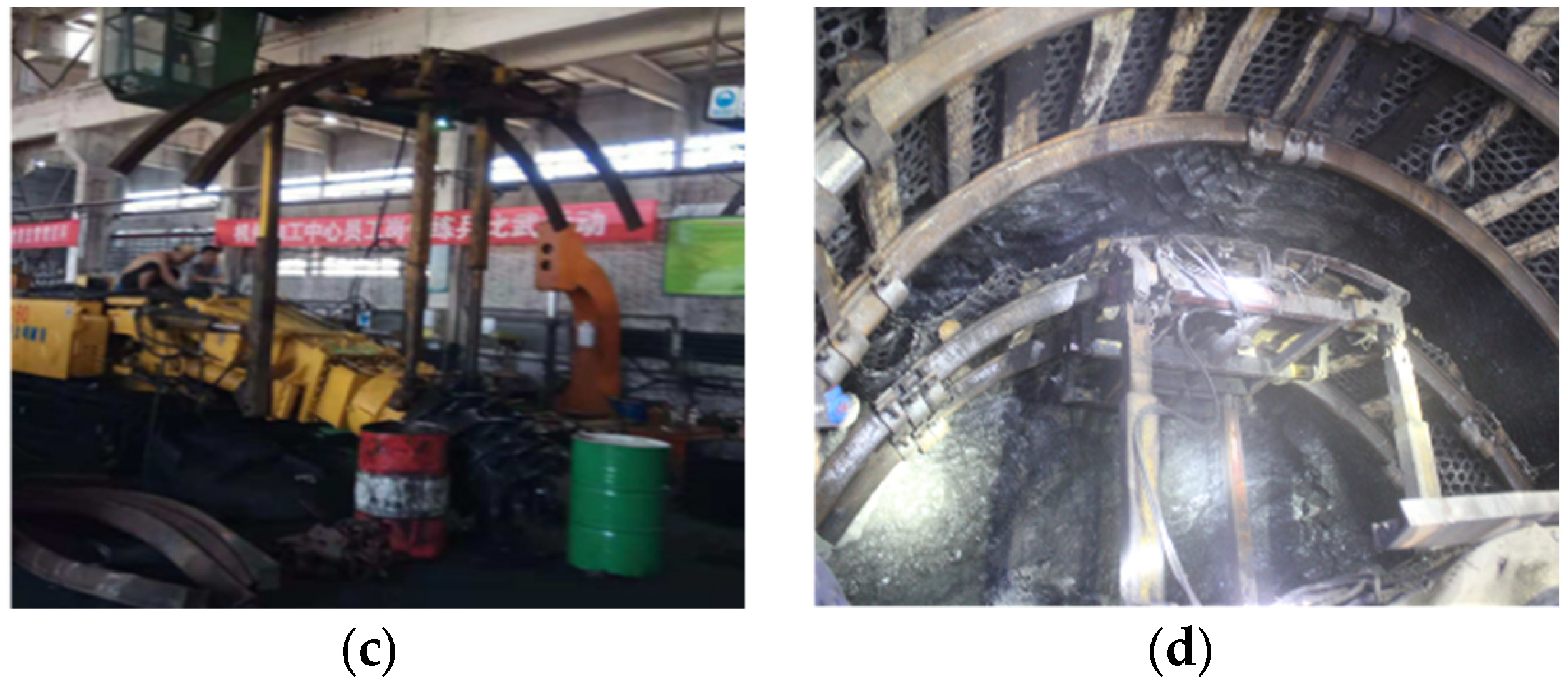
To solve the temporary support for the heading face of shed roadways, a ZLJ-10 onboard temporary support device was jointly introduced so that section cutting and support erection process continuously. As the mining road section of the 3098 working face is an arch, to adapt to the roof shape of an arch roadway, the ZLJ-10 onboard temporary support device was modified into a new onboard temporary support device for long excavation, as shown in Figure 16. The top frame is bent to a level such that the bending radian fits with the roof of a three-centered arch roadway. The length is increased to 2.4 m to cover the whole section of the roof with the maximum URD. Two grooves at the top frame are designed to place the U-shed. The grooves are spaced 805 mm apart. Two connectors are attached to the front and rear of the top frame to increase the temporary support strength of the roof.
The new temporary support device solves the temporary support problem for the heading face of shed roadways. It also increases the efficiency from one support one excavation and one support one shed per time to two supports per cutting and two supports one shed per time. The operator works standing below the forepole support device to provide temporary support for the roof. This guarantees the construction safety of the operator, eliminates the repeated “excavation—supporting—excavation” process, effectively improves the construction efficiency of support erection, and allows safe, rapid heading of shed roadways.

6. Field Application and Effect

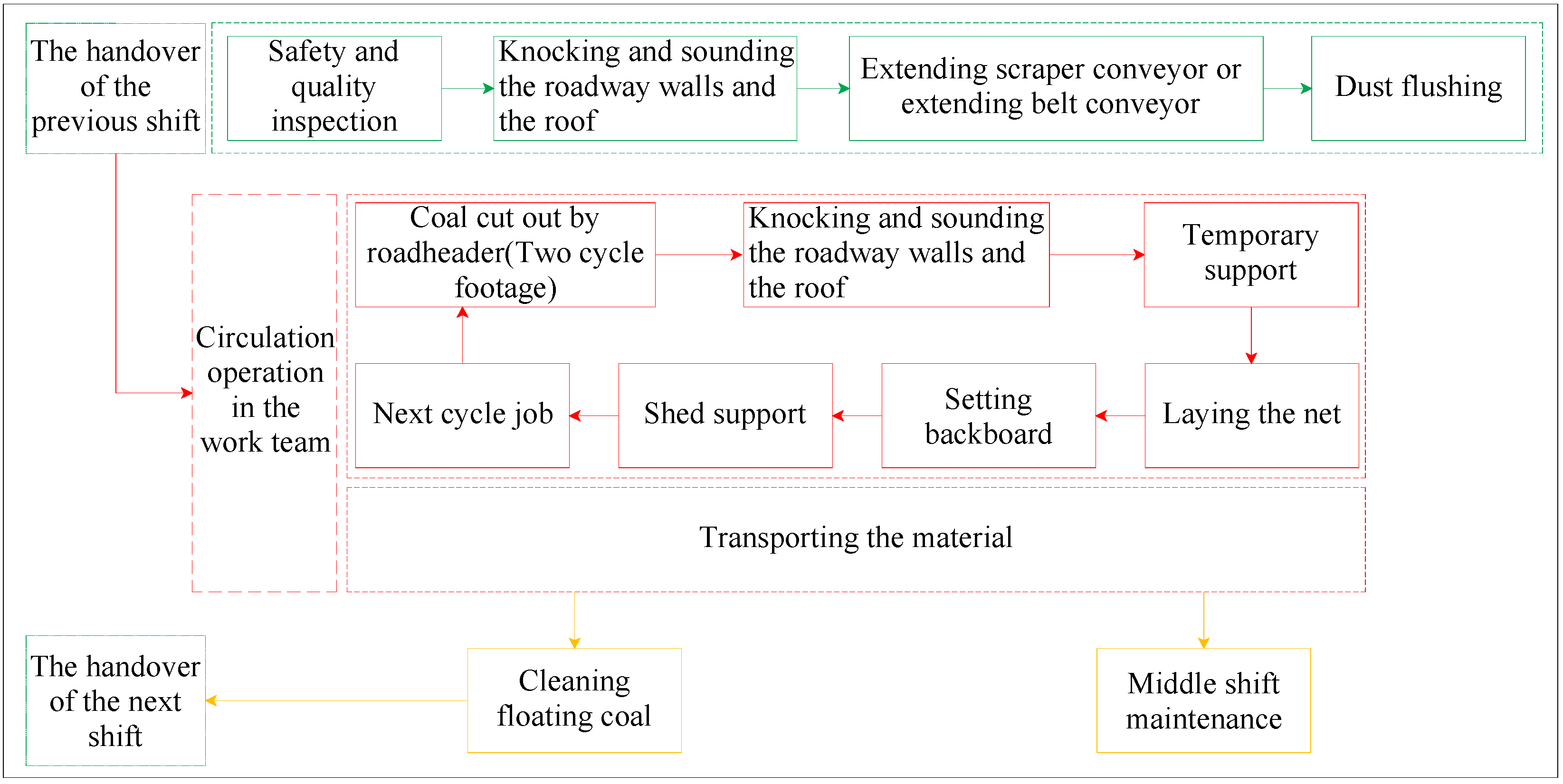
After the theoretical calculation of URD and the modification of the roadheader equipment, the existing underground construction process was optimized, and the process steps and manning were refined using the modified standing platform, the new onboard temporary support device for long excavation, and other associated equipment. This greatly improves the working efficiency, accelerates the cycle progress, and reduces workers’ labor time. Figure 17 shows the general process flow chart of the “two supports one excavation” one-through roadway forming technique for the heading face of the coal mine.
After the URD is increased to cut two rows per time and the rapid heading equipment and construction process are optimized, with the 6 o’clock and 14 o’clock shifts working nine cycles and the 22 o’clock shift performing maintenance tasks, the footage per cycle is 1.7 m and the footage per day is 30.6 m. If the roadway surrounding rock is stable and the process steps between the two sheds and the shed leg erection and shed beam joining can progress in parallel with no mutual influence at all, 10 cycles can be completed per shift at a footage of 1.7 m per cycle and 34 m per day. This ensures that the coal roadway will be headed at the monthly footage of over 550 m and the minimum time per cycle is not more than 50 min.
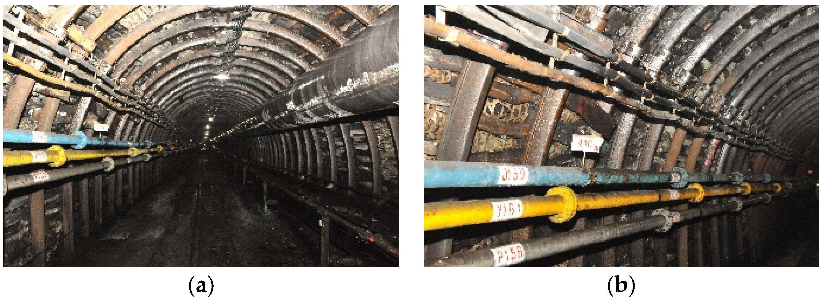
From field application in the said mine, the maximum temporary URD per cutting cycle is up to 2.3 m. One excavation two supports at 850 mm shed spacing are achieved so that section cutting and support erection can progress continuously to accelerate roadway forming. From January to July 2021, the average footage per month was more than 550 m and peaked at 846.4 m. The footage per shift was 16 supports totaling 14.1 m. As fewer workers are needed, the heading efficiency is much higher. The forming quality of shed-supported roadways is quite good. Within the influence radius of advance support stress of the working face, the maximum roadway side deformation is 460 mm and the maximum roof subsidence is 280 mm, well able to accommodate the normal mining of the working face. Figure 18 shows the roadway as supported on-site.

7. Conclusions

In this paper, the thin shell theory and the moment free theory are used to study the surrounding rock stability of an arched roadway, and verified by numerical simulation and field application, and the following conclusions are obtained:
(1)
Based on the thin shell theory, a top cover cylindrical shell model for roadways with an arch section was built. The formula for calculating the maximum URD of an arch roof was derived. The influences of roadway width, tensile strength, buried depth, and arch height on, and their contributions to, the maximum URD were analyzed. The results showed that arch roadways are highly adaptive to varying geological conditions, and the theoretical maximum URD for the 3098 heading face is 2.4 m.
(2)
Numerical simulation revealed that when the URD is around 2 m, the roadway surrounding rock is well stable and the roadway is free of tensile failure. When the URD increases beyond 4 m, tensile failure occurs on the roadway sides and the roadway becomes less stable. Therefore, a maximum URD of 2–3 was used for numerical calculation. New failure occurs on the arch roof with the increase in URD, suggesting that an arch roof has the best stability. Properly increasing URD helps a U-steel to gain support strength quickly. In the shallow part of the roadway surrounding rock under goaf, where failures are prominently concentrated, as further failure will occur at points where horizontal stresses are concentrated, failures are primarily determined by horizontal stresses.
(3)
A combined onboard standing platform + onboard beam lift device and a new onboard temporary support device for long excavation were developed as a solution to the low shed and temporary support efficiency for roadways with a URD of 2.4 m. When these devices are used on-site in conjunction with the optimized process flow, the average footage per month is over 550 m with a peak of 846.4 m; the footage per shift is 16 supports totaling 14.1 m. The forming quality of a shed-supported roadway is good enough to accommodate normal mining of the working face, consequently the rapid heading of the roadway.

Author Contributions

Conceptualization, Y.B. and C.W.; methodology, Y.B. and Y.H.; software, C.W.; validation, M.W., Y.B. and C.W.; formal analysis, Y.H.; investigation, Y.B. and C.W.; resources, Y.B.; writing—original draft preparation, Y.B. and C.W.; writing—review and editing, Y.H. and M.W.; visualization, C.W. All authors have read and agreed to the published version of the manuscript.

Funding

This research received no external funding.

Conflicts of Interest

The authors declare no conflict of interest.

References

  1. Shi, Y.; Ye, Y.; Hu, N.; Jiao, Y.; Wang, X. Physical Simulation Test on Surrounding Rock Deformation of Roof Rockburst in Continuous Tunneling Roadway. Minerals 2021, 11, 1335. [Google Scholar] [CrossRef]
  2. Wang, X.R.; Wang, E.Y.; Liu, X.F. Micromechanisms of coal fracture: Insights from quantitative AE technique. Theor. Appl. Fract. Mech. 2021, 114, 103000. [Google Scholar] [CrossRef]
  3. Wang, G.; Guo, Y.; Wang, P. A new experimental apparatus for sudden unloading of gas-bearing coal. Bull. Eng. Geol. Environ. 2020, 79, 857–868. [Google Scholar] [CrossRef]
  4. Wang, K.; Guo, Y.; Xu, H. Deformation and permeability evolution of coal during axial stress cyclic loading and unloading: An experimental study. Geomech. Eng. 2021, 24, 519–529. [Google Scholar]
  5. Wang, H.; Wang, L.J.; Zhang, X.F. Theory and technology of efficient excavation with the integration of excavation and anchor. J. China Coal Soc. 2020, 45, 2021–2030. [Google Scholar]
  6. Cheng, H.; Tang, B.; Tang, Y.Z.; Yao, Z.S.; Wang, C.B.; Rong, C.X. Full face Hard Rock Roadheader for deep roadway and its key technology for rapid construction. J. China Coal Soc. 2020, 45, 3314–3324. [Google Scholar]
  7. Du, Q.J.; Zhao, Q.F.; Yang, Z.; Guo, J.Z. Research and Practice on rapid tunneling of large section coal roadway under complex geological conditions. Coal Eng. 2013, 45, 76–79. [Google Scholar]
  8. Yang, R.S.; Wang, X. Study on rapid tunneling construction technology of large section semi coal rock roadway. China Min. Mag. 2012, 21, 87–88. [Google Scholar]
  9. Wang, X.F.; Zhang, D.S.; Shao, P.; Zhang, W. Rapid tunneling technology of deep soft rock bolt shotcrete support roadway. J. Min. Saf. Eng. 2011, 28, 415–419. [Google Scholar]
  10. Rostami, J. Development of a Force Estimation Model for Rock Fragmentation with Disc Cutters through Theoretical Modeling and Physical Measurement of Crushed Zone Pressure; Colorado School of Mines: Golden, CO, USA, 1997; Volume 38, pp. 56–64. [Google Scholar]
  11. Yi, H.; Ouyang, Z.; Zhou, X.; Li, Z.; Chen, J.; Li, K.; Liu, K. Study on the Modification of Confining Rock for Protecting Coal Roadways against Impact Loads from a Roof Stratum. Minerals 2021, 11, 1331. [Google Scholar] [CrossRef]
  12. Ahmad, M.; Hu, J.L.; Hadzima Nyarko, M.; Ahmad, F.; Tang, X.W.; Rahman, Z.U.; Nawaz, A.; Abrar, M. Rockburst Hazard Prediction in Underground Projects Using Two Intelligent Classification Techniques: A Comparative Study. Symmetry 2021, 13, 632. [Google Scholar] [CrossRef]
  13. Aslannezhad, M.; Keshavarz, A.; Kalantariasl, A.; Aslannezhad, M.; Keshavarz, A.; Kalantariasl, A. Evaluation of mechanical, chemical, and thermal effects on wellbore stability using different rock failure criteria. J. Nat. Gas Sci. Eng. 2020, 78, 103278. [Google Scholar] [CrossRef]
  14. Hu, G.J.; Yang, T.H.; Zhou, J.R.; Yu, Q.L.; Xie, L.K.; Liu, H.L.; Zhao, Y.; Taheri, A. Mechanism of Surrounding Rock Failure and Crack Evolution Rules in Branched Pillar Recovery. Minerals 2017, 7, 96. [Google Scholar] [CrossRef] [Green Version]
  15. Justo, J.; Castro, J.; Cicero, S.; Sanchez, C.M.; Husillos, R. Notch effect on the fracture of several rocks: Application of the Theory of Critical Distances. Theor. Appl. Fract. Mech. 2017, 90, 251–258. [Google Scholar] [CrossRef] [Green Version]
  16. Girard, J.; Silber, R.E.; Mohiuddin, A.; Chen, H.Y.; Karato, S. Development of a Stress Sensor for In-Situ High-Pressure Deformation Experiments Using Radial X-ray Diffraction. Minerals 2020, 10, 166. [Google Scholar] [CrossRef] [Green Version]
  17. Yu, Y.; Wang, X.; Bai, J.; Zhang, L.; Xia, H. Deformation Mechanism and Stability Control of Roadway Surrounding Rock with Compound Roof: Research and Applications. Energies 2020, 13, 1350. [Google Scholar] [CrossRef]
  18. Zhang, N.; Han, C.L.; Xie, Z.Z. Theory and efficient support technology of continuous beam roof control in coal roadway. J. Min. Form. Control. Eng. 2019, 1, 48–55. [Google Scholar]
  19. Ma, H.W.; Wang, S.B.; Mao, Q.H.; Shi, Z.W.; Zhang, X.H.; Yang, Z.; Cao, X.G.; Xue, X.S.; Xia, J.; Wang, C.W. Key common technologies for intelligent excavation of coal mine roadways. J. China Coal Soc. 2021, 46, 310–320. [Google Scholar]
  20. Ma, H.W.; Wang, P.; Wang, S.B.; Mao, Q.H.; Shi, Z.W.; Xia, J.; Yang, Z.; Xue, X.S.; Wang, C.W. Intelligent parallel collaborative control method for coal mine excavation robot system. J. China Coal Soc. 2021, 46, 2057–2067. [Google Scholar]
  21. Zhang, Z.Q.; Chen, F.F.; Li, N.; He, M.M.; Moayedi, H. Influence of Fault on the Surrounding Rock Stability for a Mining Tunnel: Distance and Tectonic Stress. Adv. Civ. Eng. 2019, 2019, 2054938. [Google Scholar] [CrossRef]
Figure 1. Comprehensive histogram of the 3098 working face.
Minerals 12 01329 g001
Figure 2. Schematic diagram of the section layout of the 3098 haulage roadway and airway shed support.
Minerals 12 01329 g002
Figure 3. Cylindrical shell mechanical model.
Minerals 12 01329 g003
Figure 4. Top cover cylindrical shell model of a roof in an unsupported roof area of an arch roadway.
Minerals 12 01329 g004
Figure 5. Analysis of the geometric relationship of a top cover cylindrical shell.
Minerals 12 01329 g005
Figure 6. Schematic diagram of a semielliptical top cover cylindrical shell.
Minerals 12 01329 g006
Figure 7. Roadway roof URDs under different influencing factors. (a) Roadway width vs. URD. (b) Buried depth vs. URD. (c) Tensile strength vs. URD. (d) Arch height vs. URD.
Minerals 12 01329 g007
Figure 8. Maximum URD variation rates under different influencing factors.
Minerals 12 01329 g008
Figure 9. Numerical calculation model of a certain mine.
Minerals 12 01329 g009
Figure 10. Development and distribution of a roadway plastic zone under different URDs. (a) Plastic zone at a URD of 2 m. (b) Plastic zone at a URD of 4 m. (c) Plastic zone at a URD of 6 m. (d) Plastic zone at a URD of 8 m. (e) Plastic zone at a URD of 10 m.
Minerals 12 01329 g010
Figure 11. Nephograms of axial stress and vertical displacement of a U-steel section under different URDs. (a-1) Axial stress of a U-steel section at 2 m behind the heading face. (a-2) Axial stress of a U-steel section at 4 m behind the heading face. (a-3) Axial stress of a U-steel section at 6 m behind the heading face. (a-4) Axial stress of a U-steel section at 8 m behind the heading face. (a-5) Axial stress of a U-steel section at 10 m behind the heading face. (b-1) Vertical displacement of a U-steel section at 2 m behind the heading face. (b-2) Vertical displacement of a U-steel section at 4 m behind the heading face. (b-3) Vertical displacement of a U-steel section at 6 m behind the heading face. (b-4) Vertical displacement of a U-steel section at 8 m behind the heading face. (b-5) Vertical displacement of a U-steel section at 10 m behind the heading face.
Minerals 12 01329 g011
Figure 12. Comparison of axial stress and the vertical displacement of a U-steel section under different URDs.
Minerals 12 01329 g012
Figure 13. Development and distribution of a plastic zone of a roadway surrounding rock under different angles between maximum horizontal stress and the roadway. (a) Roadway plastic zone under vertical angle. (b) Roadway plastic zone under horizontal angle.
Minerals 12 01329 g013
Figure 14. Distribution diagram of vertical stress and horizontal stress of a roadway. (a) Horizontal stress distribution. (b) Vertical stress distribution.
Minerals 12 01329 g014
Figure 15. Combined onboard standing platform + onboard beam lift device. (a) 1st generation. (b) 2nd generation. (c) 3rd generation.
Minerals 12 01329 g015
Figure 16. New onboard temporary support device for long excavation. (a) Temporary support device. (b) Onboard roadheader. (c) As supported. (d) Field support.
Minerals 12 01329 g016aMinerals 12 01329 g016b
Figure 17. Optimized process flow chart.
Minerals 12 01329 g017
Figure 18. Field roadway support effect. (a) Overall effect. (b) Local effect.
Minerals 12 01329 g018
Table 1. Maximum URDs under different influencing factors.
Roadway Width/m4.04.55.05.56.06.5
Theoretical max URD/m2.01.921.881.841.821.8
Buried depth/m300400500600700800
Theoretical max URD/m2.822.442.181.991.841.72
Tensile strength/MPa0.650.750.850.951.051.15
Theoretical max URD/m1.611.731.841.952.052.14
Arch height/m0.61.01.41.82.22.6
Theoretical max URD/m0.991.31.581.842.132.45
Table 2. Model physicomechanical parameters of strata in a certain mine.
Rock StratumThickness
(m)
Unit Weight
(kg·m−3)
Bulk Modulus
(GPa)
Shear Modulus
(GPa)
Internal Angle of Friction
(°)
Tensile Strength
(MPa)
Cohesion (MPa)
Siltstone13.42·5602.11.6381.9352.1
Carbonaceous clay rock1.72·5302.01.5361.1751.9
Siltstone2.32·6503.342.8281.361.68
Fine sandstone5.12·7002.581.88422.612.4
Siltstone4.22·5602.11.6381.9352.1
8# coal3.61·3801.81.43280.851.1
Siltstone1.52·5602.11.6381.9352.1
Medium fine sandstone2.52·6002.31.8402.152.2
Siltstone fine sandstone interbedded1.32·7102.691.98422.6752.5
9# coal2.81·3801.81.43280.851.1
Siltstone1.62·5602.11.6381.9352.1
Fine sandstone3.42·7002.581.88422.612.4
Siltstone2.52·5602.11.6381.9352.1
Fine sandstone5.82·7002.581.88422.612.4
Table 3. The development and application history of the combined onboard standing platform + onboard beam lift device.
SeriesInput and Use TimeFeatures
1st generation2009.8–2016.4One single manipulator, hydraulic powered, serves as a mechanical beam lift only.
2nd generation2016.5–2017.4A standing platform added to the 1st generation to allow the worker to insert the back plate for the upper roof support safely and provide the needed standing space.
3rd generation2017.5–presentA 90° rotating beam fixing function added to the 2nd generation so that when the roof is broken, the operator can fix the beam from the side instead of the front of the heading face and then rotate the beam to the heading face prior to the next step.
Publisher’s Note: MDPI stays neutral with regard to jurisdictional claims in published maps and institutional affiliations.