Article

Energy Evolution Law during Failure Process of Coal–Rock Combination and Roadway Surrounding Rock

1
College of Energy and Mining Engineering, Shandong University of Science and Technology, Qingdao 266590, China
2
State Key Laboratory of Water Resource Protection and Utilization in Coal Mining, Beijing 102209, China
3
Shandong Energy Group Co., Ltd., Jinan 250014, China
*
Author to whom correspondence should be addressed.
Minerals 2022, 12(12), 1535; https://doi.org/10.3390/min12121535
Submission received: 31 October 2022 / Revised: 18 November 2022 / Accepted: 26 November 2022 / Published: 29 November 2022

Abstract

:
The deformation and failure of a coal–rock system in a deep environment is affected by its own mechanical properties, natural endowments, and geological structures; it is very important to study the energy evolution law of coal–rock systems. For this purpose, a Particle Flow Code in 2 Dimensions (PFC2D) simulation was conducted to assess the coal–rock structure and roadway surrounding rock. The hard roof would produce a rebound “energy supply” phenomenon when the coal was destroyed, and the influence of rock strength on the energy evolution of the coal–rock combination was analyzed. In addition, the energy evolution law of roadway surrounding rock with different roof strength is studied; the energy evolution process of roof and coal seam and deep and shallow coal mass are compared, according to the energy storage characteristics of roadway surrounding rock in different areas; the partition energy storage model of roadway surrounding rock is established preliminarily and the concepts of energy storage area and energy supply area of roadway surrounding rock are proposed; the prevention and control methods of near-field rock burst in deep roadways are discussed, and the research conclusions can provide theoretical reference for the research on the mechanism of rock burst in deep coal mines.

1. Introduction

With the increase of mining depth and intensity, the number of rock burst mines in China, Poland, Kazakhstan, Ukraine, and other places, as well as the rock burst risk, have significantly increased [1,2,3,4,5]. According to incomplete statistics, 86.8% of rock bursts occur near roadways [6,7,8]. Under complex conditions, such as large mining depth, high ground stress, and strong disturbance, coal deformation and failure are not only related to physical and mechanical properties, occurrence conditions, and geological structure, but are also affected by the coal–rock system [9,10,11].
Numerous studies have been conducted to simplify the coal–rock system into a coal–rock combination. These studies have focused on the stress–strain relationship, peak strength, elastic modulus, and Poisson’s ratio, among other mechanical parameters [12,13]. In terms of the combination failure pattern, scholars have studied the radial deformation and dilatation characteristics of different combination positions and failure concentration location. Yin et al. [14] used PFC2D particle flow numerical simulation software to carry out uniaxial compression tests on rock–coal mass containing penetrating joints in coal samples, and analyzed the influence of joints on the strength and failure characteristics of rock–coal mass. Chen et al. [15] studied the progressive failure mechanism of a roof–coal pillar structure. Zuo et al. [16] obtained acoustic electrothermal (AE) precursor information for crack propagation. The basic mechanical properties and failure pattern of coal–rock combination have been recognized. However, coal–rock masses are often in a multidirectional loading state; therefore, analyzing the mechanical properties and failure mechanism of combinations under biaxial and triaxial loading conditions will provide significant insights to guide practical engineering. Hence, others have studied the influence of lateral and confining pressures on the failure characteristics and crack development of a coal–rock structure. Lu et al. [17] carried out the true triaxial test to study the disaster mechanism caused by rock burst in deep coal mines.
In fact, rock burst is a dynamic failure phenomenon driven by energy in a coal–rock system. Mining, disturbance, or pressure relief in the coal seam are always accompanied by energy input, accumulation, dissipation, and release [18,19]. Therefore, the study of coal/rock deformation and failure law from the perspective of energy may be a suitable approach for elucidating the mechanism of failure in a coal–rock structure [20,21]. Accordingly, a large number of studies have been conducted on the energy evolution process of rock bursts, including energy accumulation, transfer, and release. Wang et al. [22] studied energy evolution mechanism during sandstone fail process. Zuo et al. [23] obtained the energy nonlinear evolution characteristics, and established an instability energy model of coal–rock structure. In addition, a certain type of rock burst mechanism has been revealed from an energy perspective. Feng et al. [24] studied the excavation-induced microseismicity activity and the rock burst mechanism, and obtained similarities and differences between deep parallel tunnels with alternating soft–hard strata. Yu et al. [25] established mechanical models of the fracturing processes of thick hard rock strata based on the thick plate theory. In addition, the energy index has been measured to evaluate the rock burst risk of a coal–rock structure. Pan et al. [26] proposed the new impact energy speed indicator considering the time effect, the critical soften areas coefficient and the critical stress coefficient. Christopher et al. [27] gave the prevention and control methods of rock burst and successfully applied them in coal mines. While this research has provided important data regarding the energy evolution law of rock bursts, the energy mechanism underlying rock bursts in roadways in deep coal mines remains unclear. In particular, the partition energy evolution law of near-field roadway surrounding rock during the rock burst process requires detailed analysis.
Consequently, scholars have carried out a lot of research on the energy evolution law of coal–rock structures. However, due to the large difference in roadway size from the field, it is difficult for the laboratory test results to guide the coal mine production effectively. On the related research of rock burst of roadway surrounding rock, scholars mostly use the field monitoring method; it can reflect the deformation and stress distribution characteristics of roadway surrounding rock [28,29]. Sotskov et al. studied the character of stress redistribution while changing the distance from the working face to drift is described, but there are few studies on the energy evolution law of roadway surrounding rock. The essence of rock burst is the energy accumulation–release process. Therefore, it is of great significance to reveal the energy evolution law of roadway surrounding rock for guiding roadway and tunnel rock burst prevention.
Given that a coal or rock mass is composed of mineral particles, particle flow software can simulate its mesoscopic characteristics, thus constituting an effective method for studying the energy evolution law of a coal–rock system at the mesoscopic level [30,31]. In this study, the failure process of small-scale coal–rock combination and large-scale roadway surrounding rock is simulated by Particle Flow Code in 2 Dimensions (PFC2D), and the influence of rock strength on the energy evolution of coal–rock structure is analyzed. Moreover, the energy partition evolution process for roadway surrounding rock is studied, and the partition energy storage model of roadway surrounding rock is established. Finally, a partition prevention and control method for roadway surrounding rock bursts is proposed, which can provide theoretical reference for prevention and control of roadway rock bursts in coal mines.

2. Numerical Model Establishment

2.1. Simulation of Coal–Rock Combination

The PFC2D software was used to simulate uniaxial loading of the coal–rock combination, which was conducted in two steps:
(1)
Figure 1 shows the standard specimens, including coal and rocks, were calibrated. The model size was 50 × 100 mm, and the radius expansion method was used to generate the specimens. Generally, the parallel bond model is used to represent dense materials, such as coal and rock [10]. The model included two kinds of contact interfaces: one was an infinitesimal linear elastic interface, and the other was a linear elastic bond interface with a specific size (parallel bond). The mesoscopic parameter setting of the model primarily comprised the particle elastic model and bond strength between particles. Figure 2 shows the stress–strain curve and failure pattern of the calibrated model. After the model was generated, the load was applied to the specimens by moving the upper and lower walls at a loading speed of 0.01 mm/s. The mesoscopic parameters and basic mechanical parameters of coal and rock are listed in Table 1, and the radius, parallel bonding radius, and friction for all lithology are 0.2–0.3 mm, 1, and 0.15, respectively.
(2)
Based on the calibrated coal and rocks, five kinds of coal–rock combination with different rock strengths were established. The model size was 50 × 100 mm, and the coal–rock height ratio was 1:1. The model establishment and parameter selection method are the same as those used in step 1. The coal–rock interface adopts a linear contact model [9]. Changes in stress, strain, and energy were monitored and recorded using the fish function during the loading process.

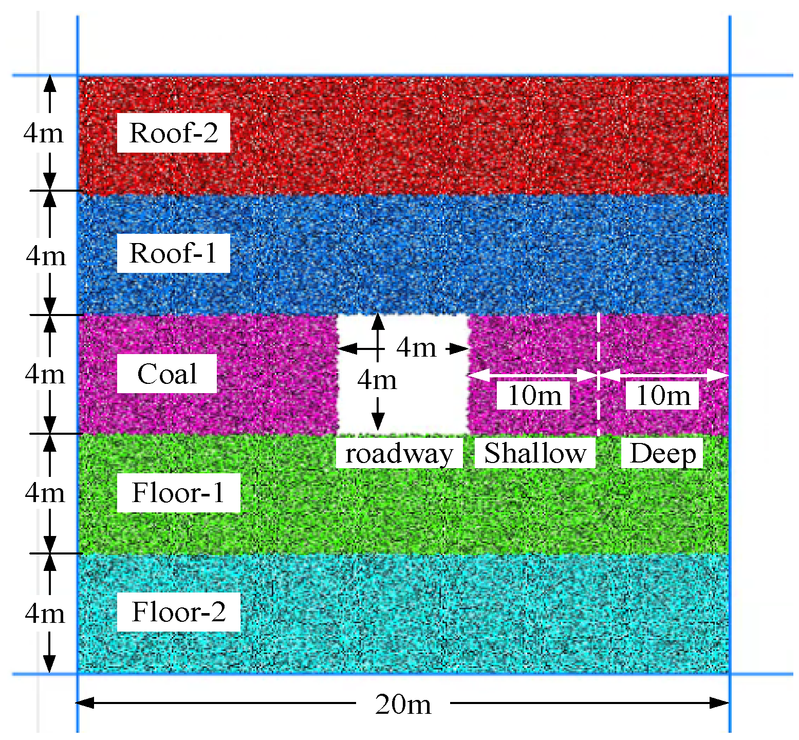
2.2. Simulation of Roadway Surrounding Rock

Figure 3 shows the established model of particle flow in a roadway surrounding rock. To further analyze the energy evolution law of roadway surrounding rock, a numerical model of roadway surrounding rock was established. The model size was 20 × 20 m. The parameters included roof-2, coal seam, floor-1, and floor-2, which corresponded to rock-5, coal, rock-4, and rock-5, respectively. The selected parameters of roof-1 were rock-1, rock-2, and rock-3, and the models corresponding to roof-1 were designated RSR-1, RSR-2, and RSR-3, respectively. The height of each rock layer was 4 m, and a 4 × 4 m (width × height) roadway was excavated in the middle of the coal seam. The displacement loading method was adopted to control the upper and lower walls of the model for loading, and the wall movement speed was 0.01 mm/s. Displacement of the left and right walls was fixed to simulate the deep roadway surrounding rock. The mesoscopic parameters and basic mechanical parameters of coal and rock mass are listed in Table 1. The coal seam within 10 m on the outside of the roadway was defined as shallow coal mass, while the coal seam within 10–20 m on the outside of the roadway was defined as deep coal mass. The number of cracks, strain energy, and dissipation energy were monitored during the loading process.

3. Failure Characteristics and Energy Evolution of Coal–Rock Structure

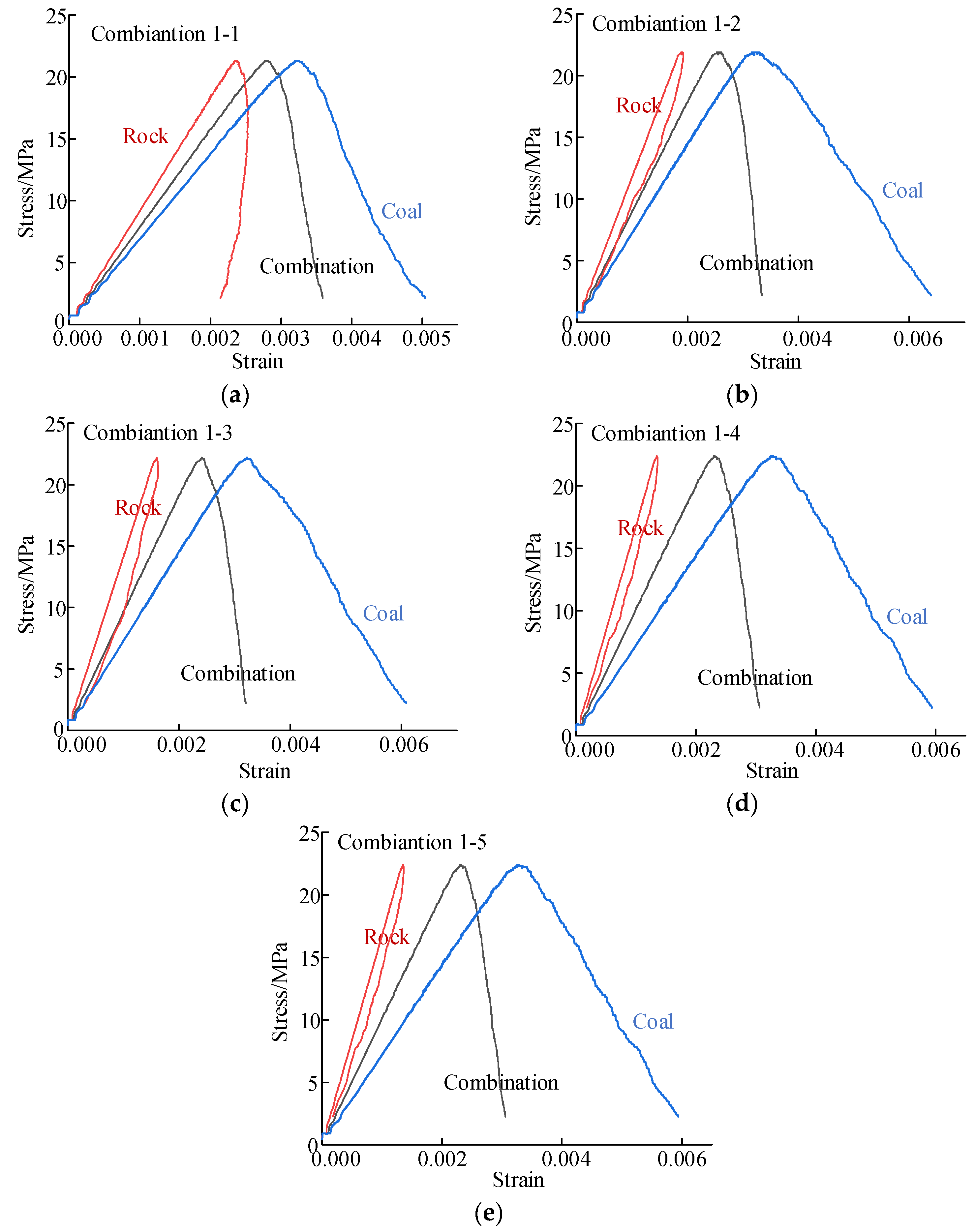
3.1. Stress–Strain Curve and Failure Characteristics of Coal–Rock Structure

Figure 4 shows the stress–strain curves of the rock and coal combinations under uniaxial loading. With increasing strain, the combination stress first increases linearly and then gradually decreases after the peak stress. The curve can be divided into three stages: linear elastic deformation, unstable deformation, and post-peak strain softening. Different rock strength has minimal effect on the stress–strain curve of the combinations. The stress–strain curve of the coal component was similar to that of the combination, showing an initial increase followed by a decrease as the strain increased. The stress–strain curve of the rock component increased linearly with increasing strain, and after the coal component failed, the curve retracted to form a hysteresis loop. The area of the hysteresis loop represented the amount of dissipation energy produced by rock; the higher the rock strength, the smaller the hysteresis loop area, indicating that the rock component accumulated strain energy persistently during the loading process. Thus, the coal component failed while the rock did not completely fail, so as to restore the deformation and release the accumulated strain energy. The combination 1-1 had the lowest rock strength, and the rock deformation was not completely recovered in the post-peak stage, indicating significant plastic deformation in the combination 1-1, resulting in serious failure.
Figure 5 shows the failure characteristics of the coal–rock combinations. As presented in Figure 5a, the number of cracks increased exponentially with increasing timestep, which can be divided into two stages, namely, the calm and rising stages. The timestep from 0 to 2 × 10⁴ constituted the calm stage, in which a few cracks were generated and the combination deformed elastically. In contrast, the timestep from 2 × 10⁴ to 3.11 × 10⁴ constituted the rising stage, during which the number of cracks began to increase, and a higher rock strength decreased the crack increase rate.
The combinations mainly presented sheared failure (Figure 5b). When the rock strength was 26.16 MPa (combination 1-1), the cracks first generated inside the coal component, and then gradually extended to the rock component. Finally, the combination failed in the form of coal–rock co-shearing; with an increase in rock strength (combinations 1-2, 1-3), the number of cracks inside the rock component gradually decreased. When the rock strength exceeded 70 MPa (combinations 1-4, 1-5), cracks rarely occurred inside the rock component, and the combination failed in the form of coal component shear failure. It was observed that with increasing rock strength, the number of cracks inside the combination gradually decreased, and the combination failed in the form of coal component shear failure. When the coal and rock had similar strengths, the cracks inside the coal mass rapidly expanded and penetrated the rock component, resulting in local damage inside the rock mass.

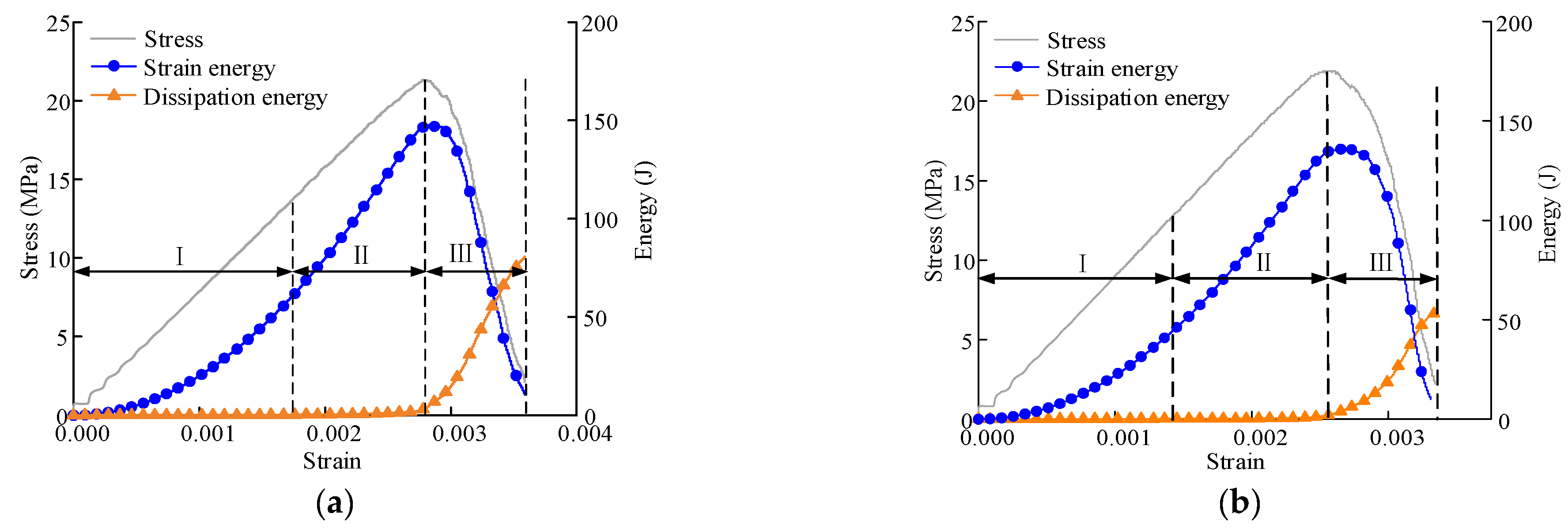
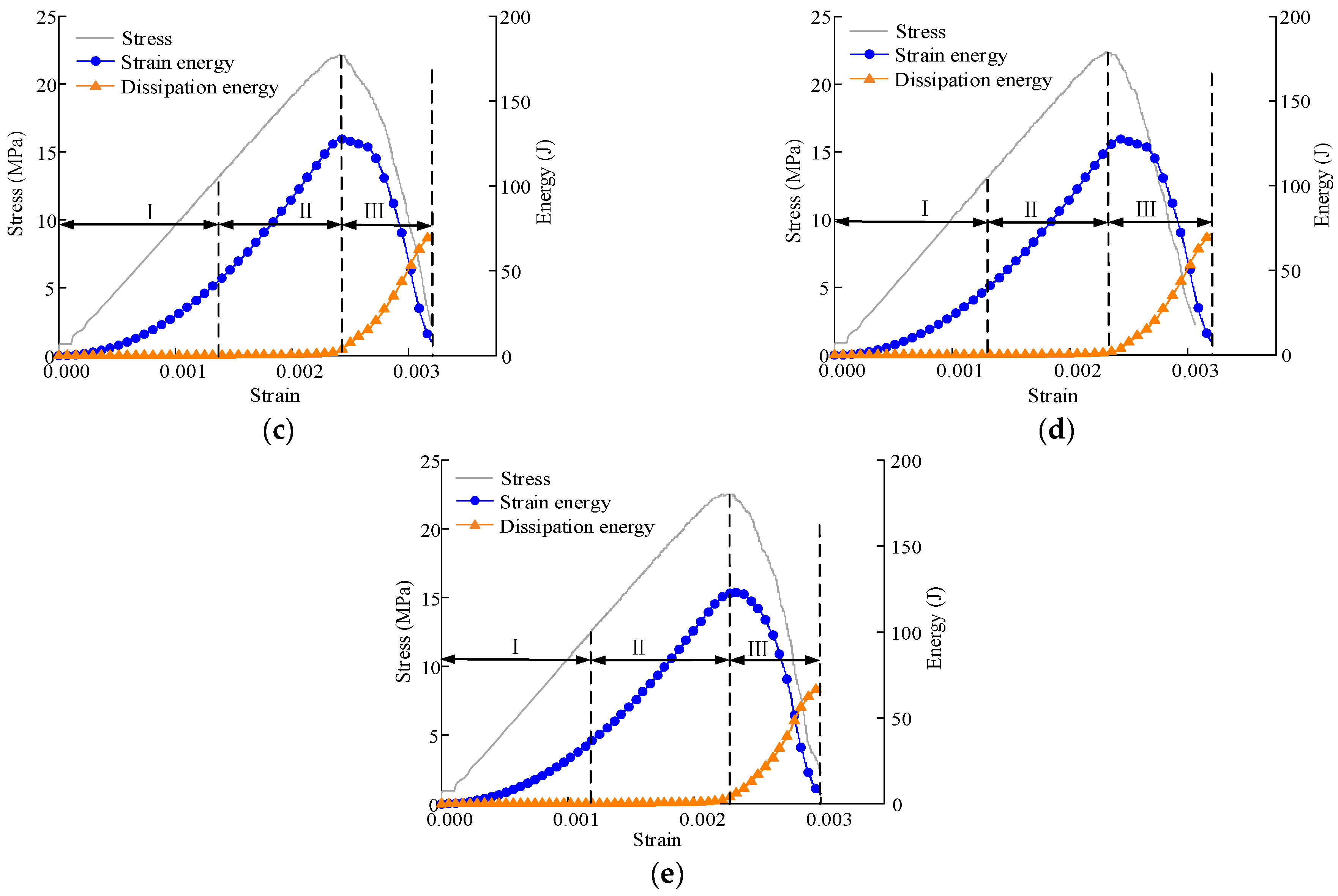
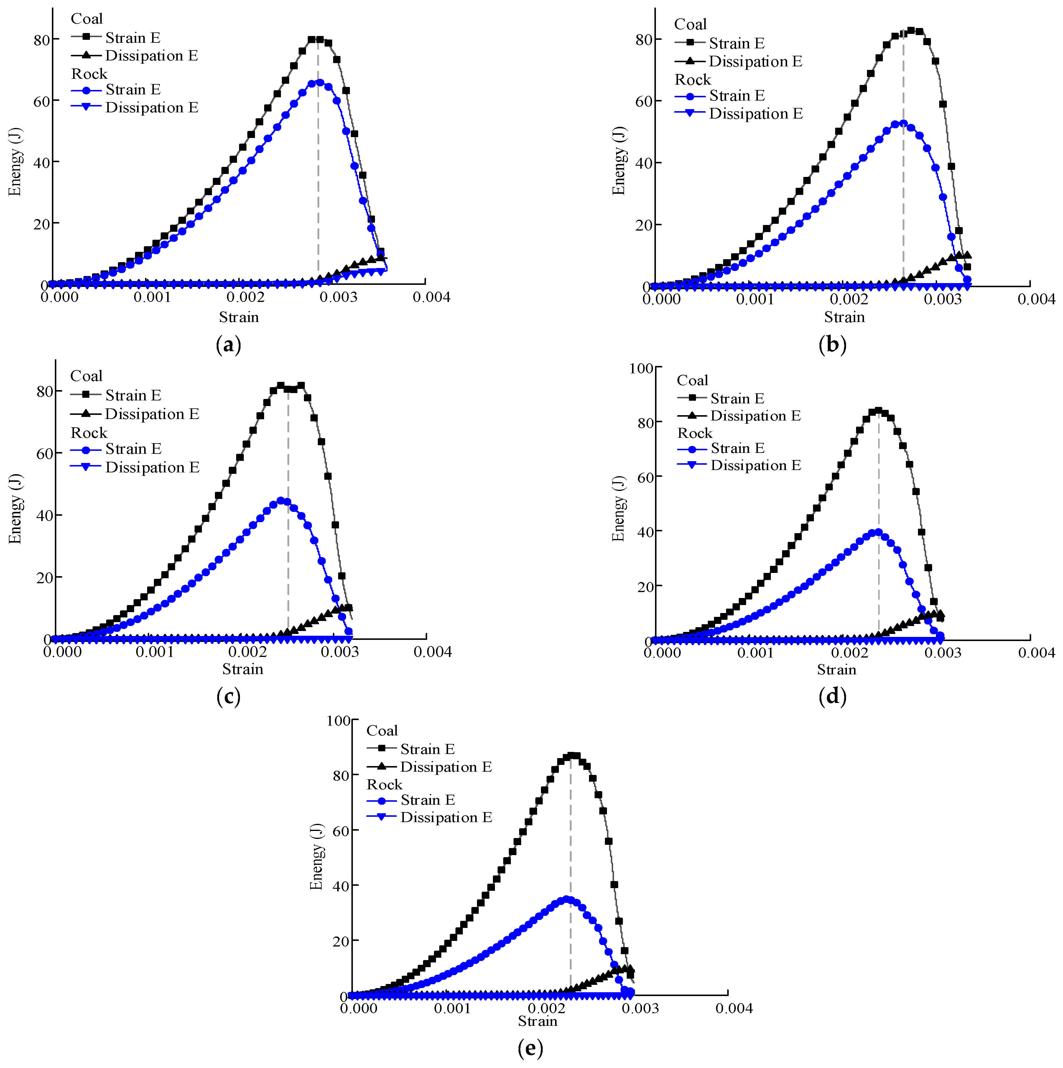
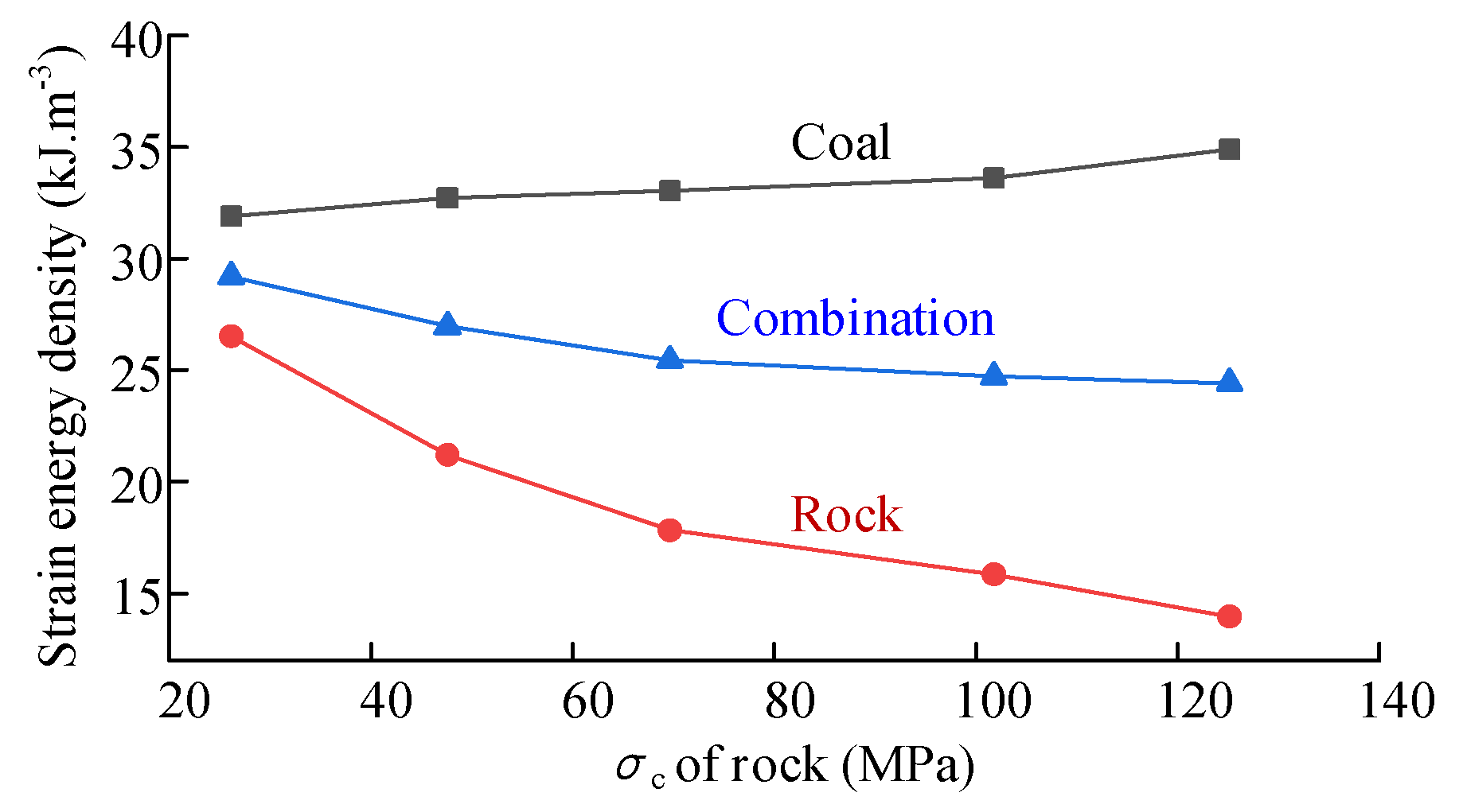
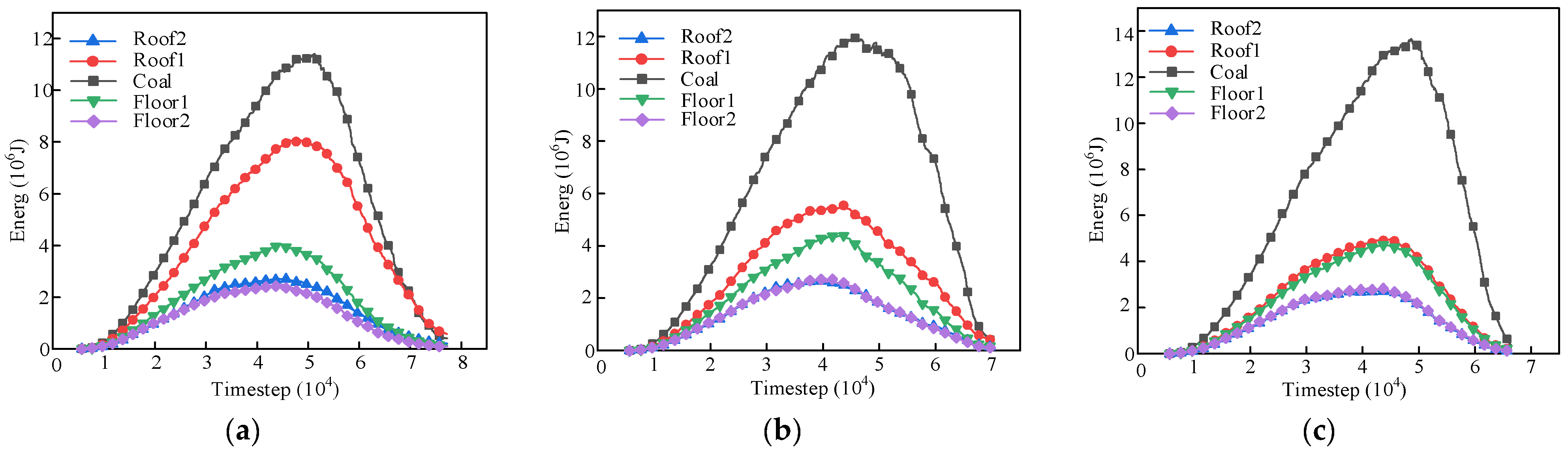
3.2. Energy Evolution of Coal–Rock Structure

The energy evolution law of all combinations was similar (Figure 6). At the prepeak stage, both strain energy and dissipation energy exhibited upward trends; at the post-peak stage, strain energy was rapidly released, whereas dissipation energy was rapidly accumulated.
According to the strain energy evolution process, the energy evolution curve of the coal–rock combinations can be divided into three stages. Stage I: the strain energy increased slowly, whereas the dissipation energy was near 0. At this stage, the strain energy accumulation rate increased gradually, constituting the strain energy rapid accumulation phase of the stress–strain curve, comprising the phases from elastic deformation to stable development of microcracks. Stage II: the strain energy continued to increase, however, its accumulation rate decreased; moreover, the accumulation rate decreased to 0 near the peak stress, whereas the dissipation energy gradually increased. This stage corresponded to the unsteady crack propagation phase of the stress–strain curve. Stage III: upon reaching the peak point, strain energy accumulated inside the combination, reaching the extreme value, and was subsequently rapidly released and reduced to the minimum value after the coal component failed, whereas the dissipation energy increased rapidly and finally stabilized. This stage corresponded to the post-peak phase of the stress–strain curve. In addition, minimal difference was observed in the energy evolution law between different rock strength combinations, and rock strength had little effect on energy accumulation in the combinations.
Figure 7 shows the partition energy evolution law of the coal–rock combinations under uniaxial compression. The strain energy evolution law inside the coal component was consistent with that of the combination. As rock strength increased, strain energy gradually accumulated inside the coal component. When the rock strength was 26.166, 47.592, and 69.659 MPa, the maximum strain energy inside the coal component was 79.7, 81.8, and 82.6 J, respectively. This is due to the hard rock indirectly increasing the peak strength of coal, leading to higher accumulation of strain energy inside the coal component. In addition, as rock strength increased, strain energy accumulation in the rock component gradually decreased; when the rock strength was 26.166, 47.592, and 69.659 MPa, the maximum strain energy within the rock component was 66.3, 53.1, and 44.6 J, respectively. That is, the stronger the rock, the less strain it has when it is subjected to the same stress.
In addition, the strain energy and dissipation energy in the coal component were higher than those in the rock component. In particular, the largest difference in strain energy between the two components was approximately one time, indicating that the coal component was the main carrier of strain energy in the combination, and that dissipation energy in the rock component was markedly lower than that in the coal component at the post-peak stage. This is because stronger rocks are less likely to fail. Therefore, the dissipation energy evolution of the coal and rock components is related to the combination failure.
According to the first law of thermodynamics, assuming that there is no heat exchange between the coal–rock combination and the outside environment during the loading process, a portion of the treatment performed on the specimen by a testing machine was converted into strain energy, while the other part was consumed in the form of dissipation energy. According to Hooke’s law, the strain energy of coal–rock combination can be expressed as follows:
U = U e + U d
U e = U r e + U c e = 1 2 σ 1 ε r + 1 2 σ 1 ε c σ 1 2 2 E r + σ 1 2 2 E c
where U is the work performed by testing machine; Ue is the elastic strain energy density; Ud is the dissipation energy density; Uce is the elastic strain energy density of coal; Ure is the elastic strain energy density of rock; σ1 is the axial stress value; εc and εr are the strains of coal and rock, respectively; Ec and Er are the elastic moduli of coal and rock, respectively.
Figure 8 shows the strain energy density partition evolution curve of the composite at peak strength. According to Equation (2), the strain energy density of the coal–rock combination is proportional to its peak stress and inversely proportional to the elastic modulus of coal and rock. The increase in combination peak stress was small, and the rock elastic modulus increased; therefore, the strain energy density of the combination tended to decrease. Given that the strain energy density of the coal component was largely affected by the combination peak stress, it tended to increase slowly. The peak strain energy density of the coal component was 14.73 kJ/m3. However, in the coal–rock combination, the strain energy density of the coal component increased significantly. For instance, when the rock strength was 26.16 MPa, the strain energy density of the coal component was 31.88 kJ/m3, which was 53.81% higher than that of the single coal component. Furthermore, the coal strain energy density continued to gradually increase. When the rock strength exceeded the coal strength, the energy storage limit of the coal could be increased; however, the increase was limited. The strain energy density of the rock component in the combination decreased nonlinearly because during the loading process, the coal body was first damaged when the rock had not reached its peak strength. The higher the rock strength, the lower the strain at peak stress, resulting in a lower strain energy density.

4. Failure Pattern and Partition Energy Evolution of Roadway Surrounding Rock

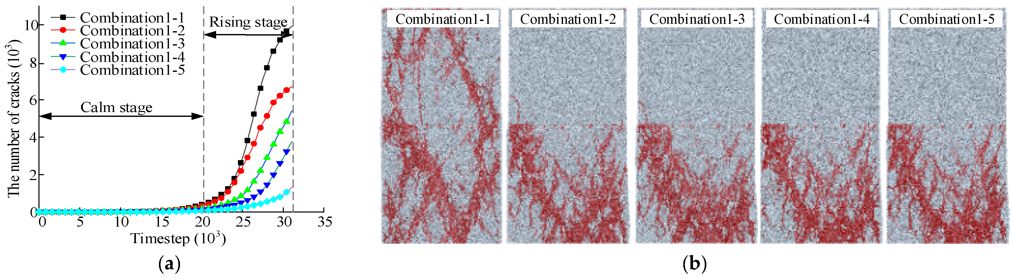
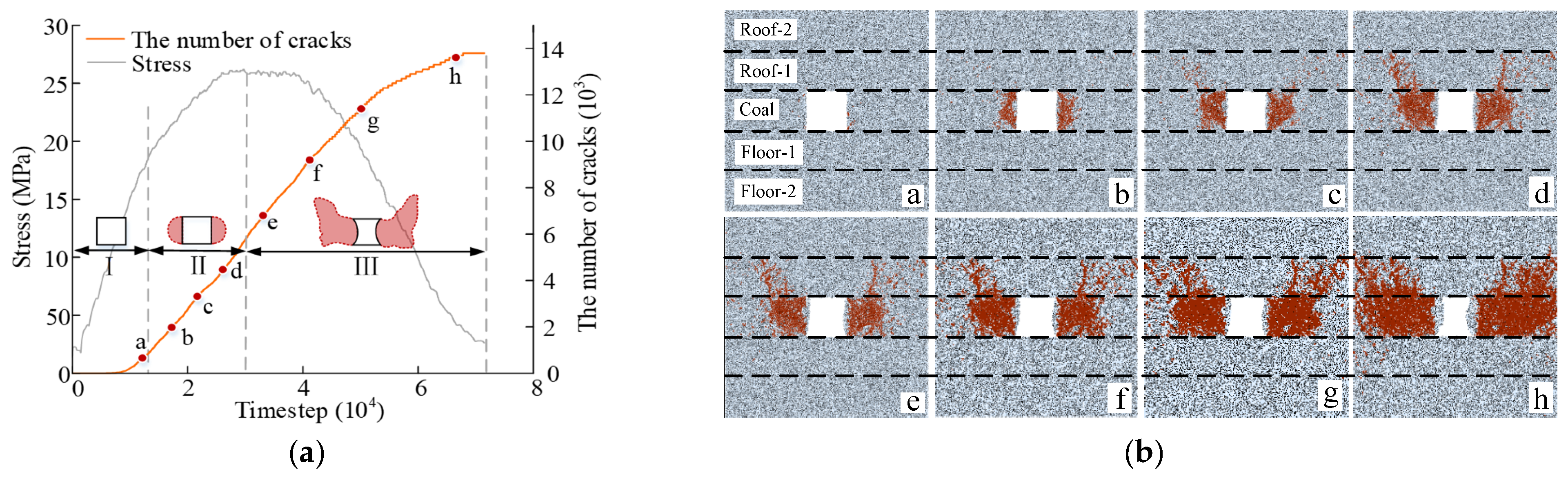
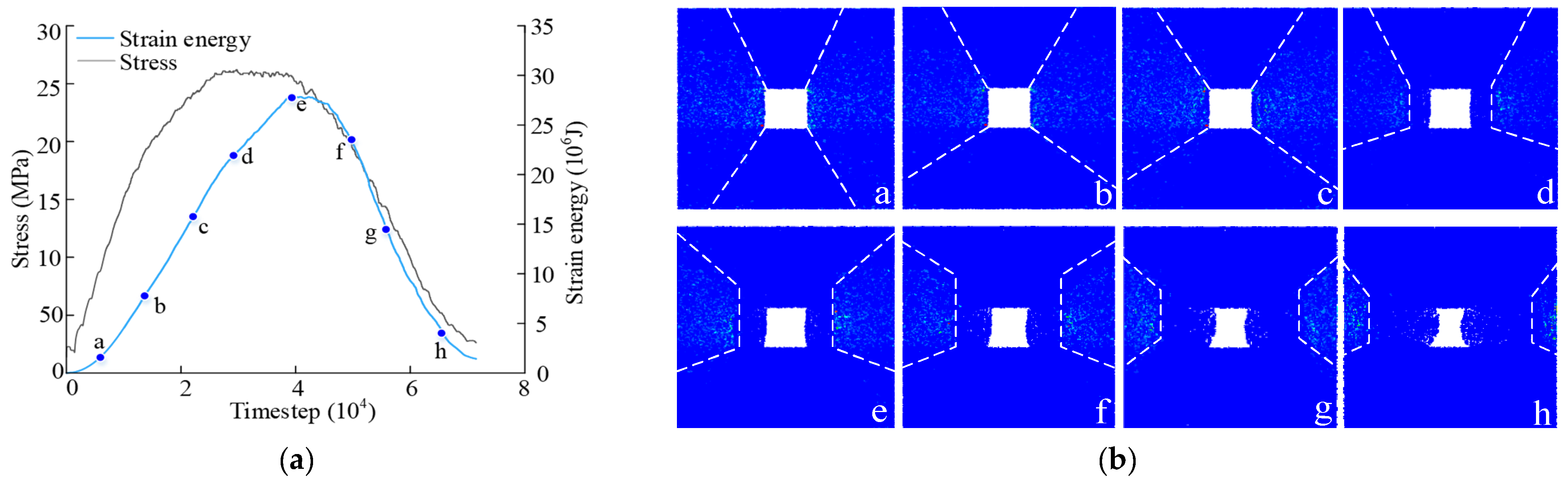
4.1. Failing Pattern of Roadway Surrounding Rock

Figure 9 shows the progressive failure process of roadway surrounding rock. For the RSR-1, the number of cracks increased nonlinearly with increasing timestep. According to the stress change curve, the process can be divided into three stages. During stage I, the stress showed a linear increasing trend, and the roadway surrounding rock underwent elastic deformation without cracking. During stage II, the stress exhibited a nonlinear trend and approached the stress peak, and the roadway surrounding rock began to undergo plastic deformation. Cracks first developed at the bottom corner of the two sides of the roadway and then extended upward. The cambium crack structure was destroyed in the shallow surrounding rock of both sides; the cracks then transferred to the coal in the deep plastic zone. Thus, deformation of the surrounding rock of the roadway side was prominent. During stage III, the stress gradually decreased, and the number of cracks in the direct roof and direct bottom strata increased significantly. Some cracks also extended from the direct roof to the basic roof (similar to the bottom plate). The surrounding rock of both sides of the roadway became obviously protruded. Subsequently, with increasing wall displacement, the surrounding rock of the two sides of the roadway further protruded, and the coal seam was completely destroyed.
The cracks first developed in the shallow coal mass of the roadway side, transferred to the deep coal, and extended to the roof and floor. Finally, cracks were distributed in a “butterfly” pattern, and both sides of the roadway surrounding rock gradually transformed from protruding deformation to protruding failure. The coal mass with weak strength was the main failure area among the rock layers; a few cracks were detected in roof-1 and floor-1 with higher strength, while no apparent cracks appeared in roof-2 or floor-2 with the highest strength.

4.2. Partition Energy Evolution of Roadway Surrounding Rock

The strain energy evolution process of roadway surrounding rock was similar to that of the combination, and can be divided into four stages: initial accumulation, near peak, rapid release, and gradual release (Figure 10). During stage I, the strain energy increased, first gradually then rapidly, whereas the increase in dissipation energy was not obvious, and the roadway surrounding rock mainly produced elastic deformation. During stage Ⅱ, the strain energy increase rate decreased gradually, reaching the energy storage limit. In contrast, the elevation rate of dissipation energy increased gradually, and the roadway surrounding rock began to fail on a large scale. During stage III, the strain energy gradually decreased, whereas the dissipation energy continued to increase, exceeding the strain energy at the end of this stage. During stage Ⅳ, the strain energy decreased slowly and approached 0, whereas the dissipation energy continued to increase. However, the increase tended to be small, indicating that the degree of roadway surrounding rock failure was relatively high during this stage. The internal dissipation energy of roadway surrounding rock was low during stage Ⅰ and began to increase in stage Ⅱ. Moreover, the elevation rate of dissipation energy increased during stage Ⅲ, but tended to decrease in stage Ⅳ, indicating that the sudden increase in dissipation energy inside rock mass is a significant feature of burst failure.
The strain energy evolution law of each rock layer was similar to that of the whole surrounding rock (Figure 11). During the loading process, the strain energy of roadway surrounding rock was primarily stored in coal mass as the strength of the coal component was smaller than that of the rock component. The strength of roof-1 was lower than that of floor-1, and more strain energy was accumulated in roof-1 than in floor-1; the strength of roof-2 was the same as that of floor-2, with the lowest strain energy accumulation detected in roof-2 and floor-2.
The higher the roof-1 strength, the lower the strain energy accumulation in roof-1 (Figure 11a–c). When the strength of roof-1 approached that of roof-2, only a slight difference was present in strain energy between roof-1 and roof-2; as roof-1 strength increased, strain energy accumulation in the coal mass increased. When the roof-1 strength increased from 26.17 to 69.66 MPa, strain energy accumulation in the coal mass increased from 1.14 × 10⁷ to 1.37 × 10⁷ J. This result suggested that coal mass was the main strain energy accumulation area in the roadway surrounding rock system. The hard roof also accumulated a low amount of strain energy; the higher the roof strength, the lower the strain energy accumulation. In addition, the hard roof can improve the energy storage limit of coal mass; the greater the roof strength, the more strain energy accumulated in the coal mass.
The strain energy of both shallow and deep coal mass initially increased and then decreased (Figure 12). Before the strain energy accumulated in the shallow coal mass peaked, the strain energy elevation rate of the deep coal mass was the same as that of the shallow coal mass. After the strain energy accumulated in the shallow coal mass peaked, the strain energy accumulated in deep coal mass continued to increase and then decreased until reaching the peak value. It was observed that the strain energy accumulated in the shallow coal mass reached its peak value first; however, it was obviously lower than that in the deep coal mass. This was because during the failing process of roadway surrounding rock, the coal mass was first compressed to accumulate strain energy, and then, with increasing stress, the shallow coal mass failed, and the accumulated strain energy was released. Meanwhile, the deep coal mass was in the elastic state, continuing to accumulate strain energy. Finally, the whole coal mass failed, and the strain energy accumulated in the deep coal mass was released to 0.
In addition, as the roof-1 strength increased, the peak value of strain energy accumulated in both shallow and deep coal masses gradually increased. The strain energy in the shallow coal mass increased from 2.06 × 10⁶ to 2.49 × 10⁶ J, while that in the deep coal mass increased from 1.12 × 10⁷ to 1.35 × 10⁷ J, supporting the conclusion that increasing roof strength will enhance the energy accumulation limit of coal.

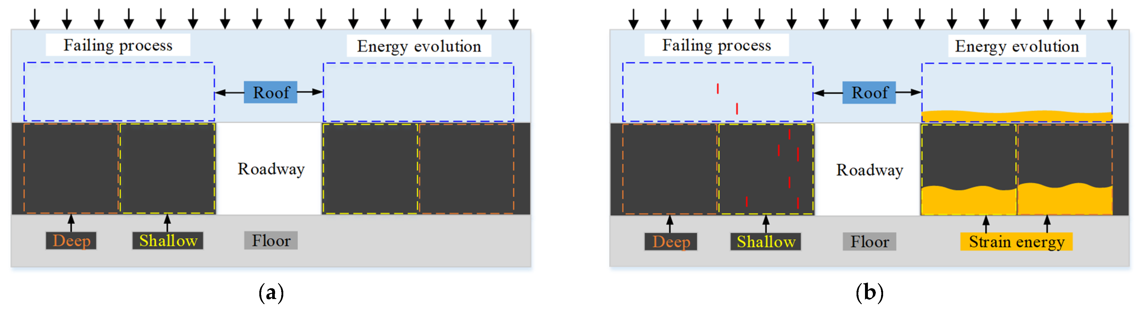
5. Partition Energy Storage Model of Roadway Surrounding Rock and Its Application

A large number of rock burst field cases show that both sides of roadway surrounding rock comprise the main failure area in the occurrence of rock bursts [30]. This is an evolutionary process of energy accumulation, transfer, and release. If the energy storage pattern and characteristics of near-field roadway surrounding rock are known, the roadway surrounding rock structure can be weakened accordingly, thus avoiding accumulation of large amounts of strain energy in the roadway surrounding rock, which will result in rock bursts. The related literature shows that the burst area is primarily concentrated in the near-field area of roadway surrounding rock, which is mainly composed of shallow failing coal mass, deep elastic coal mass, roof, and floor (Figure 13). The energy released by the roadway surrounding rock originates not only from the shallow coal mass but also from the deep coal mass, roof, and floor; therefore, the strain energy accumulated in all components of roadway surrounding rock jointly affects the rock burst intensity [31].
Figure 14 shows the strain energy distribution evolution law of roadway surrounding rock during the loading process. During the linear stress increase stage, the strain energy in the roadway surrounding rock was fan-shaped on both sides, gathering in the shallow coal mass, whereas the roof and floor of the upper and lower regions of roadway did not accumulate strain energy owing to small deformation (Figure 14a–c). During the near-peak stress stage, the strain energy accumulation area shifted to the deep coal mass, and the shallow coal mass failed (Figure 14d). Meanwhile, during the post-peak stage, the shallow coal mass failed completely, and strain energy was mainly concentrated in the deep elastic coal mass (Figure 14e–g). When the stress dropped to 0, the coal mass failed completely, and the strain energy was largely concentrated in roof-1 on both sides of the roadway, whereas a small amount of strain energy was distributed in other rocks (Figure 14h).
Figure 15a illustrates the partition energy storage model of roadway surrounding rock. During the initial accumulation of strain energy, vertical cracks parallel to the maximum principal stress began to develop inside the shallow coal mass (Figure 15b). The cracks first developed from the shallow coal mass (Figure 9), and the internal energy storage of coal was higher than that of hard roof (Figure 11). Moreover, during the initial strain energy accumulation stage, the strain energy accumulated inside the shallow coal mass was slightly higher than that in the deep coal mass (Figure 12). This was due to the presence of larger coal mass deformations and greater strain energy accumulation closer to the excavation roadway.
Figure 15c shows the middle stage of strain energy accumulation in the roadway surrounding rock. With the increase of stress, microcracks further developed inside the shallow coal mass and connected with each other to form large-scale cracks; microcracks also developed in the deep coal mass and roof. In the strata, the strain energy stored in the coal mass remained higher than that in the roof (Figure 11). In the coal mass, the rate of strain energy accumulation decreased owing to the cracks that developed in the shallow coal mass, whereas strain energy rapidly accumulated in the deep coal mass owing to its high integrity. This phenomenon is also reflected in Figure 12; when the shallow coal mass was close to the energy storage peak, the deep coal mass was still rapidly accumulating strain energy.
Figure 15d shows the peak value of strain energy accumulation in the roadway surrounding rock. When the stress exceeded the bearing limit of the shallow coal mass, or when the shallow coal mass reached its energy storage limit (high static loading condition), the shallow coal mass failed. The failure severity was ascribed to four categories from small to large: macroscopic cracks, slight splints, serious splints, and complete collapse. In the strata, according to Figure 9 and the engineering site, the roof would not completely fail during the mining process; at the moment of shallow coal mass failure, the roof would release strain energy to supply coal in a “rebound” manner, thus aggravating the severity of shallow coal mass failure. As shown in Figure 12, upon shallow coal mass failure, the accumulated strain energy was released, whereas strain energy accumulation increased in the deep coal mass. According to accurate static loading in the simulation, in theory, when the shallow coal mass failed, under the lateral restriction of the elastic area and expansion, the strain energy accumulated in the deep coal mass would be released and transferred to the shallow coal mass.
As Figure 15a shows, the black, light blue, and gray areas, respectively, represent coal seam, roof, and floor. A roadway is excavated in the coal seam, and the areas delineated by dotted lines on the left and right sides of the roadway represent the surrounding rock load area. The blue, yellow, and orange areas, respectively, represent the loading area of roof, shallow coal mass, and deep coal mass. The left and right sides of the figure reflect the partition failure characteristics and the strain energy evolution process of roadway surrounding rock. The strain energy is depicted by the orange area, and vertical cracks parallel to the maximum principal stress appear as red lines.
Figure 15b shows the initial accumulation stage of strain energy (orange area) in the roadway surrounding rock. The cracks first develop from the shallow coal mass, the internal energy storage of coal is higher than that of hard roof, and in the initial strain energy accumulation stage, the strain energy accumulated inside the shallow coal mass is slightly higher than that of the deep coal mass. Figure 15c shows the middle stage of strain energy accumulation in the roadway surrounding rock. With the increase of stress, the microcracks inside the shallow coal mass are further developed and connected to form large-scale cracks. Subsequently, the rate of strain energy accumulation of coal decreases due to the cracks developed, while the strain energy can be rapidly accumulated in deep coal mass due to its good integrity. Figure 15d shows the peak value of strain energy accumulation in the roadway surrounding rock. When the stress exceeds the bearing limit of the shallow coal mass, or the shallow coal mass reaches its energy storage limit (high static loading condition), the shallow coal mass will fail.
During the rock burst process, the energy storage area was the shallow coal mass on both sides of the roadway; however, this would ultimately fail owing to stress overload or energy overload. The roof and deep elastic coal mass on both sides of the roadway constituted the energy supply area. When the shallow coal mass failed, the constraining force of the lower roof and deep lateral coal would suddenly decrease. In contrast, the compressed roof would recover deformation, and the confined deep coal mass would expand laterally; both processes would release strain energy to supply the shallow coal mass, which had shifted to dissipation energy of crack propagation and kinetic energy of coal ejectment. Therefore, the energy storage area and energy supply area jointly influenced the occurrence and intensity of rock bursts.
Figure 16 presents the partition prevention and control diagram of roadway rock bursts. According to the partition energy storage characteristics of near-field roadway surrounding rock, roadway rock bursts can be controlled according to the principle of “source differentiation”. That is, when the mechanical properties of coal mass and roof are weak, the risk of rock burst is small. At this point, only bolts (cables) are needed to reinforce the shallow coal mass of the roadway side to prevent its excessive deformation (Figure 16a). When coal mass has a certain bursting risk, rock bursts may occur. The roof is weak, and to prevent the deep elastic coal mass from supplying energy, a pressure-relief method, such as large-diameter drilling, is necessary to break up the structural integrity of the deep coal mass (energy supply zone; Figure 16b). In the shallow coal mass (energy storage area), a bolt (cable) support is used to improve the performance of the shallow coal mass and prevent its outburst. This concept was subsequently evolved into the “unloading-solid” cooperative control mechanism. When a hard thick roof is above the coal seam, the roof will increase the energy storage limit of the coal mass, causing more strain energy to accumulate inside the coal mass (Figure 16c,d). First, the large diameter drilling method is used to destroy the structural integrity of the deep coal, so that the deep coal mass does not supply energy. Second, hydrofracturing and loosening blast are applied to break the roof structure, so that the energy storage area and the energy supply area are not released. Finally, the shallow coal mass is strengthened by bolts (cables).
This paper studies the energy evolution law of coal–rock combination and roadway surrounding rock, and the partition energy storage model of roadway surrounding rock is established. In fact, the mechanism of rock burst is very complicated; when the roadway surrounding rock reaches the critical burst state, the far-field roof break, fault slip, and the excavation disturbance of the surrounding working face will have an impact on the roadway rock burst. In the future, the mechanism of dynamic + static load superposition-induced burst will be systematically studied.

6. Conclusions

(1)
Coal mass is the main carrier for energy storage during the loading process of a coal–rock structure. With the increase of roof strength, the accumulated strain energy of the roof decreased gradually, but the accumulated strain energy of the shallow coal mass and deep coal mass increased, and a hard roof will improve the energy storage limit of the coal mass.
(2)
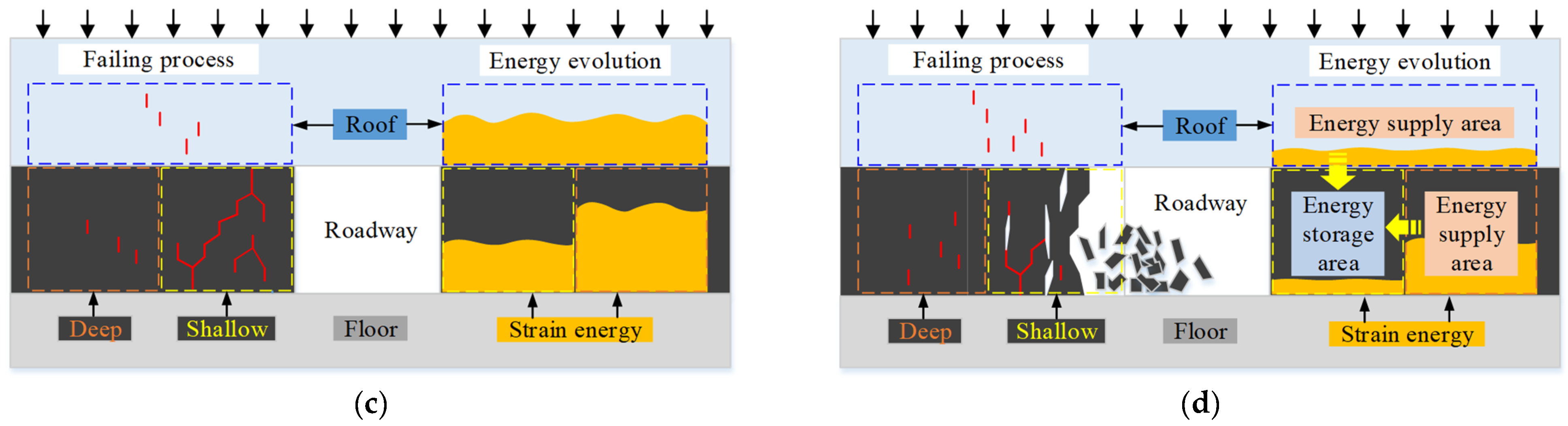
When the shallow coal mass fails, the roof provides energy to the shallow coal mass in the form of rebound, while the deep elastic coal mass provides energy to the shallow coal mass in the form of lateral expansion. The energy stored in the deep coal mass and the hard roof is the main factor leading to rock burst, and promotes dynamic failing of shallow coal mass.
(3)
The partition energy storage model of roadway surrounding rock is preliminarily established, and the concepts of energy supply zone and energy storage zone are proposed. That is, the shallow coal mass which burst-fails is defined as the energy storage area, the roof and deep elastic coal are defined as the energy supply area, and both of them participate in the rock burst evolution process of near-field roadway surrounding rock.
(4)
According to the partition energy storage model of roadway surrounding rock, the rock burst can be controlled according to the principle of “source differentiation”. By evaluating the energy storage characteristics of different areas of roadway surrounding rock, the corresponding measures can be taken to prevent and control rock burst, which is of great significance for rock burst prevention in roadways or tunnels.

Author Contributions

Methodology, D.Z.; software, D.Z.; validation, T.Z. and Y.Z.; formal analysis, Y.Z.; investigation, Y.Z.; resources, Y.C.; data curation, X.Z.; writing—original draft, D.Z.; preparation, D.Z.; writing—review and editing, D.Z.; visualization, Y.Z.; supervision, Y.C.; funding acquisition, T.Z. and W.G. All authors have read and agreed to the published version of the manuscript.

Funding

This research was funded by the Major Program of Shandong Provincial Natural Science Foundation, ZR2019ZD13; Major Scientific and Technological Innovation Project of Shandong Provincial Key Research Development Program, 2019SDZY02 and National Natural Science Foundation of China, 52274086.

Institutional Review Board Statement

Not applicable.

Informed Consent Statement

Not applicable.

Data Availability Statement

Not applicable.

Acknowledgments

Tongbin Zhao was supported by the Major Program of Shandong Provincial Natural Science Foundation, ZR2019ZD13; Weiyao Guo was supported by the National Natural Science Foundation of China, 52274086, Xiufeng Zhang was supported by the Technological Innovation Project of Shandong Provincial Key Research Development Program, 2019SDZY02.

Conflicts of Interest

The authors declare no conflict of interest.

References

  1. Zhao, T.; Zhang, P.; Guo, W.; Gong, X.; Wang, C.; Chen, Y. Controlling roof with potential rock burst risk through different pre-crack length: Mechanism and effect research. J. Cent. South Univ. 2022, 29, 1–13. [Google Scholar]
  2. Santosh, K.R.; Asfar, M.k.; Niroj, K.M.; Debashish, M.; Somu, M.; Jai, k.P. Review of preventive and constructive measures for coal mine explosions: An Indian perspective. Int. J. Min. Sci. Techno. 2022, 32, 471–485. [Google Scholar]
  3. Zhao, T.; Xing, M.; Guo, W.; Wang, C.; Wang, B. Anchoring effect and energy-absorbing support mechanism of large deformation bolt. J. Cent. South Univ. 2021, 28, 572–581. [Google Scholar] [CrossRef]
  4. Małkowski, P.; Niedbalski, Z.; Majcherczyk, T.; Bednarek, Ł. Underground monitoring as the best way of roadways support design validation in a long time period. Min. Miner. Depos. 2020, 14, 1–14. [Google Scholar] [CrossRef]
  5. Begalinov, A.; Almenov, T.; Zhanakova, R.; Bektur, B. Analysis of the stress deformed state of rocks around the haulage roadway of the Beskempir field (Kazakhstan). Min. Miner. Depos. 2020, 14, 28–36. [Google Scholar] [CrossRef]
  6. Bondarenko, V.; Kovalevska, I.; Cawood, F.; Husiev, O.; Snihur, V.; Jimu, D. Development and testing of an algorithm for calculating the load on support of mine workings. Min. Miner. Depos. 2021, 15, 1–10. [Google Scholar] [CrossRef]
  7. Łukasz, W.; Joanna, K.; Małgorzata, K. The influence of mining factors on seismic activity during longwall mining of a coal seam. Int. J. Min. Sci. Techno. 2021, 31, 429–437. [Google Scholar]
  8. Luo, Y.; Gong, F.; Li, X.; Wang, S. Experimental simulation investigation of influence of depth on spalling characteristics in circular hard rock tunnel. J. Cent. South Univ. 2020, 27, 891–910. [Google Scholar] [CrossRef]
  9. Yang, L.; Gao, F.; Wang, X. Mechanical response and energy partition evolution of coal-rock combinations with different strength ratios. Chin. J. Rock Mech. Eng. 2020, 39, 3297–3305. [Google Scholar]
  10. Zhao, T.; Yin, Y.; Tan, Y.; Wei, P.; Zou, J. Bursting liability of coal research of heterogeneous coal based on particle flow microscopic test. J. China Coal Soc. 2014, 39, 280–285. [Google Scholar]
  11. Chen, L.; Guo, W.; Zhang, D.; Zhao, T. Experimental study on the influence of prefabricated fissure size on the directional propagation law of rock type-I crack. Int. J. Rock Mech. Min. Sci. 2022, 160, 105274. [Google Scholar] [CrossRef]
  12. Liu, C.; Zhao, G.; Xu, W.; Meng, X.; Huang, S.; Zhou, J.; Wang, Y. Experimental investigation on failure process and spatio-temporal evolution of rockburst in granite with a prefabricated circular hole. J. Cent. South Univ. 2022, 27, 2930–2944. [Google Scholar] [CrossRef]
  13. Dou, L.; He, X.; Ren, T.; He, J.; Wang, Z. Mechanism of coal-gas dynamic disasters caused by the superposition of static and dynamic loads and its control technology. J. China Univ. Min. Technol. 2018, 47, 48–59. [Google Scholar]
  14. Yin, D.; Chen, S.; Chen, B.; Jiang, N.; Meng, T.; Wang, W. Simulation study on effects of coal persistent joint on strength and failure characteristics of rock-coal combined body. Geomech. Eng. 2018, 15, 1113–1114. [Google Scholar]
  15. Chen, S.; Yin, D.; Zhang, B.; Ma, H.; Liu, X. Mechanical characteristics and progressive failure mechanism of roof–coal pillar structure. Chin. J. Rock Mech. Eng. 2017, 36, 33–43. [Google Scholar]
  16. Zuo, J.; Pei, J.; Liu, J.; Peng, R.; Li, Y. Investigation on acoustic emission behavior and its time-space evolution mechanism in failure process of coal-rock combined body. Chin. J. Rock Mech. Eng. 2011, 30, 1564–1570. [Google Scholar]
  17. Lu, J.; Yin, G.; Gao, H.; Li, X.; Zhang, D.; Deng, B.; Wu, M.; Li, M. True triaxial experimental study of disturbed compound dynamic disaster in deep underground coal mine. Rock Mech. Rock Eng. 2020, 53, 2347–2364. [Google Scholar] [CrossRef]
  18. Deniz, T.; Ihsan, B.T.; Ted, k. Investigating different methods used for approximating pillar loads in longwall coal mines. Int. J. Min. Sci. Techno. 2021, 31, 23–32. [Google Scholar]
  19. Xie, H.; Peng, R.; Ju, Y.; Zhou, H. On energy analysis of rock failure. Chin. J. Rock Mech. Eng. 2005, 24, 2603–2608. [Google Scholar]
  20. He, M.; Zhao, F.; Cai, M.; Du, S. A novel experimental technique to simulate pillar burst in laboratory. Rock Mech. Rock Eng. 2015, 48, 1833–1848. [Google Scholar] [CrossRef]
  21. Bobet, A.; Einstein, H.H. Fracture coalescence in rock-type materials under uniaxial and biaxial compression. Int. J. Rock Mech. Min. Sci. 1998, 35, 863–888. [Google Scholar] [CrossRef]
  22. Wang, Y.; Cui, F. Energy evolution mechanism in process of sandstone failure and energy strength criterion. J. Appl. Geophys. 2018, 154, 21–28. [Google Scholar] [CrossRef]
  23. Zuo, J.; Song, H.; Chen, Y.; Li, Y. Post-peak progressive failure characteristics and nonlinear model of coal-rock combined body. J. China Coal Soc. 2018, 43, 3265–3272. [Google Scholar]
  24. Feng, G.; Chen, B.; Jiang, Q.; Xiao, Y.; Niu, W.; Li, P. Excavation-induced microseismicity and rockburst occurrence: Similarities and differences between deep parallel tunnels with alternating soft-hard strata. J. Cent. South Univ. 2021, 28, 582–594. [Google Scholar] [CrossRef]
  25. Yu, M.; Zuo, J.; Sun, Y.; Mi, C.; Li, Z. Investigation on fracture models and ground pressure distribution of thick hard rock strata including weak interlayer. Int. J. Min. Sci. Techno. 2022, 32, 137–153. [Google Scholar] [CrossRef]
  26. Pan, Y.; Geng, L.; Li, Z. Research on evaluation indices for impact tendency and danger of coal seam. J. China Coal Soc. 2010, 35, 1975–1978. [Google Scholar]
  27. Christopher, M. Protecting miners from coal bursts during development above historic mine workings in Harlan County, KY. Int. J. Min. Sci. Techno. 2021, 31, 111–116. [Google Scholar]
  28. Zhang, S.; Li, Y.; Shen, B.; Sun, X.; Gao, L. Effective evaluation of pressure relief drilling for reducing rock bursts and its application in underground coal mines. Int. J. Rock Mech. Min. Sci. 2019, 114, 7–16. [Google Scholar] [CrossRef]
  29. Meng, F.; Zhou, H.; Wang, Z.; Zhang, L.; Kong, L.; Li, S.; Zhang, C. Experimental study on the prediction of rockburst hazards induced by dynamic structural plane shearing in deeply buried hard rock tunnels. Int. J. Rock Mech. Min. Sci. 2016, 86, 210–223. [Google Scholar] [CrossRef]
  30. Guo, W.; Zhang, D.; Zhao, T.; Li, Y.; Zhao, Y.; Wang, C.; Wu, W. Influence of rock strength on the mechanical characteristics and energy evolution law of gypsum-rock combination specimen under cyclic loading-unloading condition. Int. J. Geomech. 2022, 22, 04022034. [Google Scholar] [CrossRef]
  31. Tan, Y.; Guo, W.; Zhao, T.; Meng, X. Coal rib burst mechanism in deep roadway and“stress relief-support reinforcement”synergetic control and prevention. J. China Coal Soc. 2020, 45, 66–81. [Google Scholar]
Figure 1. PFC2D numerical calculation model. (a) Rock, coal numerical model. (b) Coal–rock combination numerical model [9].
Minerals 12 01535 g001
Figure 2. Calibration model for stress–strain curves and failure pattern. (a) Stress–strain curves. (b) Failure pattern.
Minerals 12 01535 g002
Figure 3. Particle flow model of roadway surrounding rock.
Minerals 12 01535 g003
Figure 4. Partition stress–strain curves of coal–rock combinations. (a) Combination 1-1. (b) Combination 1-2. (c) Combination 1-3. (d) Combination 1-4. (e) Combination 1-5.
Minerals 12 01535 g004
Figure 5. Failure characteristics of coal–rock combinations. (a) The number of cracks in combination with timestep. (b) Failure pattern of combinations.
Minerals 12 01535 g005
Figure 6. Energy evolution law of coal–rock combinations. (a) Combination 1-1. (b) Combination 1-2. (c) Combination 1-3. (d) Combination 1-4. (e) Combination 1-5.
Minerals 12 01535 g006aMinerals 12 01535 g006b
Figure 7. Partition energy evolution law of combinations. (a) Combination 1-1. (b) Combination 1-2. (c) Combination 1-3. (d) Combination 1-4. (e) Combination 1-5.
Minerals 12 01535 g007
Figure 8. Partition strain energy density curves of different coal–rock combinations.
Minerals 12 01535 g008
Figure 9. Progressive failure process of roadway surrounding rock. (a) The number of cracks evolution curve of roadway surrounding rock. (b) Failure process of roadway surrounding rock.
Minerals 12 01535 g009
Figure 10. Energy evolution law of roadway surrounding rock. (a) RSR-1; (b) RSR-2; (c) RSR-3.
Minerals 12 01535 g010
Figure 11. Partition strain energy evolution law of roadway surrounding rock. (a) RSR-1; (b) RSR-2; (c) RSR-3.
Minerals 12 01535 g011
Figure 12. Partition strain energy evolution law of coal mass. (a) RSR-1; (b) RSR-2; (c) RSR-3.
Minerals 12 01535 g012
Figure 13. Classification of roadway side coal mass state.
Minerals 12 01535 g013
Figure 14. Cloud diagram of strain energy evolution of roadway surrounding rock. (a) Strain energy evolution curve of roadway surrounding rock. (b) Strain energy evolution range of roadway surrounding rock.
Minerals 12 01535 g014
Figure 15. Partition energy storage model of roadway surrounding rock. (a) Model description. (b) Initial stage of strain energy accumulation. (c) Intermediate stage of strain energy accumulation. (d) Peak stage of strain energy accumulation.
Minerals 12 01535 g015aMinerals 12 01535 g015b
Figure 16. Partition energy control method of roadway surrounding rock. (a) Anchorage support. (b) Anchorage support + large diameter hole. (c) Anchorage support + large diameter hole + loosening blasting. (d) Anchorage support + large diameter hole + hydrofracturing.
Minerals 12 01535 g016
Table 1. Mesoscopic mechanical parameters of coal and rocks.
LithologyMesoscopic Parameter CalibrationMacroscopic Mechanical Properties
Density (kg∙m−3)Parallel Bond Modulus (MPa)σc (MPa)εcElasticity Modulus (MPa × 103)
Coal18004.00 × 10914.8210.001987.458
Rock-125005.00 × 10926.1660.003049.469
Rock-225006.00 × 10947.5920.0041512.270
Rock-325007.00 × 10969.6590.0051514.079
Rock-425008.00 × 109101.80.0063616.423
Rock-525009.00 × 109125.140.0067919.052
Publisher’s Note: MDPI stays neutral with regard to jurisdictional claims in published maps and institutional affiliations.

