Abstract
High-pressure air blasting (HPAB) is one type of physical blasting technique that enhances the extraction rate of coalbed methane by impacting the coal mass with high-pressure gas to create cracks within it. First, based on the physical and mechanical parameters of the simulated coal rock mass, the RHT constitutive model of the coal rock mass was established, and its parameters were determined. Then, the laws of crack propagation and stress wave decay in coal induced by high-pressure air blasting were revealed by comparing the effect with that of equivalent explosive blasting. Next, the HPAB experiment was simulated to explore the coal crack propagation law under in-situ stress conditions. Finally, the HPAB experiment was carried out and the results of this experiment were compared with the numerical simulation results. The results indicate that the crack propagation induced by high-pressure air blasting is considered as two major stages, i.e., the crack initiation and crack propagation stage induced by the stress wave and the crack stable propagation stage induced by the duration high-pressure gas. In the case of equal energy, the peak stress wave of high-pressure gas is smaller, decays more slowly and has a longer action time, compared to explosive blasting. Therefore, the number of initial random cracks in coal mass induced by high-pressure air blasting is less, and the range of crack propagation induced by high-pressure air blasting is larger. When λ = 0 (λ is the ratio of the horizontal in-situ stress to the vertical in-situ stress), the in-situ stress in the coal seam can promote the propagation of vertical cracks but inhibit the propagation of horizontal cracks. When λ = 0.5 and 1, the in-situ stress inhibits the propagation of both horizontal and vertical cracks.
1. Introduction
Coal occupies the dominant position in China’s energy structure, and is expected to occupy about 50% of the primary energy structure by 2050 [1]. Additionally, China’s coal-bed methane reserves are huge, ranking second in the world at about 36.8 trillion cubic meters. Although the gas content in most coal mines in China is high, gas drainage is difficult due to the low permeability of the coal seams. Coal and gas outbursts, gas explosions and other disasters increase in the coal mining process [2,3,4]. Therefore, increasing coal seam permeability and enhancing gas drainage is an effective way to reduce coal mining accidents and optimize the energy structure.
Hydraulic fracturing, explosive blasting and HPAB are three coal seams’ penetration enhancement techniques used for gas drainage. Hydraulic fracturing is a technique that stimulates gas flow by injecting water to create fractures in the coal seam. However, hydraulic fracturing is less effective in increasing coal seam permeability due to the water retention effect [5,6]. Additionally, hydraulic fracturing is only applicable to areas with abundant water resources and has certain limitations. When explosive blasting is used to mine coal seams with high methane content, a coal mine disaster is likely to occur. Therefore, HPAB has been the focus of attention and research by many experts and scholars in recent years [7,8]. HPAB is a physical blasting technology that improves coal seam permeability and increases gas drainage by instantly releasing high-pressure gas to impact the coal masses and form cracks in the coal masses. However, the study of the stress field and crack extension of coal masses under the action of HPAB is still in the preliminary stage.
Numerical simulation is an important tool to study stress evolution and crack propagation during blasting [9,10,11]. Zhu et al. [12] investigated the gas drainage and crack propagation of concrete sample under the action of HPAB by using COMSOL (Version 3.5, COMSOL, Stockholm, Sweden). Their results show that cracks induced by HPAB can significantly enhance coal seam permeability and gas drainage. In addition, some scholars have conducted numerous studies on the crack evolution of coal masses using different constitutive models of LS-DYNA. For example, Zhao et al. [13] used the HJC model to investigate the effect of bedding planes on the crack propagation of coal masses during the blasting process. Wang et al. [14] used the HJC and RHT models to simulate rock single-hole blasting, respectively. They found that the results obtained from simulations using the RHT model could describe the extent of the damage zone and crack propagation in the rock mass during blasting. However, the simulation results obtained using the HJC model cannot describe the tensile damage of the material, and it is necessary to add a failure criterion by the keyword “*MAT_ADD_EROSION” to simulate the crack extension. Both the HJC model and the RHT model are the constitutive models used for numerical simulations in LS-DYNA software (Version R7.0.0.1, Ansys, Inc., Canonsburg, PA, United States), and both can be used to characterize the dynamic behavior of materials under blast loading. The HJC model cannot be used directly to describe the crack propagation behavior of materials under explosive blasting because it does not accurately describe the tensile damage of materials. When the tensile damage criterion is added to the HJC model using the keyword “*MAT_ADD_EROSION”, the HJC model can simulate crack propagation by deleting the failed mesh elements. However, the dynamic tensile damage criterion is less easy to determine. The RHT model is a macro-scale material model that incorporates features that are necessary for a correct dynamic strength description of materials at impact relevant strain rates and pressures. The damage distribution in the material based on the RHT model can well describe the fracture extension of materials under explosive blasting without adding a failure criterion. Therefore, many experts and scholars tend to use the RHT model to simulate the blast-induced crack propagation of coal and rock masses.
Numerous studies have shown that cracks begin to initiate and propagate under the action of explosive stress waves and continue to propagate steadily as explosive gases wedge into the initial crack [15,16,17]. With the increases in coal mining depth, the influence of in-situ stress on crack propagation cannot be ignored. Yi et al. [18] and Jayasinghe et al. [19] studied the effect of in-situ stress on blast-induced crack propagation by using the RHT model. The numerical results indicate that the crack propagation trends to develop in the direction of the applied high in-situ stress. Wang et al. [20] investigated the effect of in-situ stress on rock crack propagation under repeated blasting loading. They found that when the difference between the horizontal and vertical stress is large, the crack propagation in the low in-situ stress direction is not significant under repeated blasting loading. There is a clear difference between HPAB and explosive blasting, but little research has been conducted on coal damage fracture and crack propagation law under the action of HPAB. Therefore, an in-depth study on HPAB is necessary.
In this study, the RHT model parameters are firstly determined based on the physical mechanical parameters of the coal masses. Then, the crack propagation of coal masses and stress wave attenuation patterns under the action of HPAB are investigated by comparing with equivalent explosive blasting. Next, the effects of different ratio λ and the same ratio λ of in-situ stress conditions on crack propagation are investigated. Finally, the experiment of HPAB coal mass is designed and carried out, and the simulation experiment results are compared with the numerical simulation results for verification.
2. Constitutive Model and Parameters for Coal Mass
2.1. RHT Constitutive Model for Coal Mass
The RHT model can more accurately describe the damage process of coal and rock under dynamic loading. Therefore, the RHT model is used by many domestic and foreign experts for the numerical simulation of explosive impact and projectile penetration research. As shown in Figure 1a, the brittle material exhibits elasticity properties when initially stressed. When the pressure increases to the crushing pressure of the pores within the coal rock, the pores inside the material begin to collapse and the bulk modulus of the material begins to decrease. The RHT model uses a pressure-dependent elastic yield surface, failure surface and residual surface to describe the variation of initial yield strength, damage strength and residual strength of the coal mass under dynamic loading, respectively, as shown in Figure 1b [21].

Figure 1.
The RHT model: (a) p-α equation of state; (b) stress limit surfaces and loading scenario.
The yield surface of the RHT model is described as a function of normalized pressure, Lode angle and strain rate, which can be expressed as [22]:
where fc is the uniaxial compressive strength; is the normalized yield function; is the normalized pressure, ; is the dynamic increase factor; is the strain rate, is the effective plastic strain; R3(θ, p*) is the Lode angle factor, and θ is the Lode angle.
The failure surface is given as
where is the normalized strength; A and N are the parameters of the failure surface.
The Lode angle factor R3(θ, p*) describes the reduced strength on shear and tensile meridian, which is expressed as:
where Q is the ratio of the tensile to the compressive meridian surfaces, , Q0 is the initial parameter, B is the correlation coefficient of Lode angle.
Strain rate has a large effect on the strength of the coal mass. In order to obtain the dynamic strain rate of the coal mass under different dynamic loading, the dynamic strain rate increase factor is introduced and its expression is [22]:
where is the reference strain rate under compression, ; is the reference strain rate under tension, ; ft is the tensile strength; βc is the material constant for compression, ; βt is the material constant for tension, .
2.2. Determination of RHT Model Parameters
The basic physical parameters of the simulated coal mass are obtained from the experiment of paper [23], where the density of simulated coal mass ρ0 = 1.82 g/cm3, uniaxial compressive strength fc = 30 MPa, wave velocity C0 = 2480 m/s, porosity α0 = 1.6, elastic modulus E = 9.1 GPa and Poisson’s ratio ν = 0.2. Then, the other parameters of the RHT model are determined according to the basic physical parameters of the simulated coal mass.
2.2.1. Determination of the Parameters of the p-α Equation of State
The equation of state for the compaction coal mass is as follows [24]:
where p is the pressure for the equation of state; μ is the volumetric strain, μ = ρ/ρ0 − 1, μ > 0 means the volume of coal mass is compressed, μ < 0 means the volume of coal rock body is expanded; e is internal energy per unit mass; B0 and B1 are the material constants and take the value of 1.22; A1, A2, A3, T1 and T2 are material parameters whose values can be obtained from the Rankine–Hugoniot equation and the Mie–Gruneisen equation of state [25,26,27,28],
The values of T1, A1, A2 and A3 are obtained as 11.19 GPa, 11.19 GPa, 13.65 GPa and 6.55 GPa, respectively, according to Equations (6)–(8). In addition, Pel is the pressure at which the material starts to fracture [29] and is taken as 10 MPa.
2.2.2. Determination of the Residual Parameters of the RHT Model
The RHT model contains a total of 34 model parameters. The parameters of the RHT constitutive model can be determined by Equations (1)–(4). The parameters for the p-α equation of state are determined by Equations (5)–(8). The remaining parameters can be determined based on the results of coal testing and preliminary research [20,21,30]. The final RHT model parameters of the simulation coal mass are obtained, as shown in Table 1.

Table 1.
The parameters of RHT model for coal mass. Fs, Ft, Gc, Gt represent relative shear strength, relative tensile strength, compressive yield surface parameter, tensile yield surface parameter.
3. Numerical Simulation of High-Pressure Gas Impact on Coal Mass
3.1. Numerical Modeling of HPAB
Since the length of the high-pressure gas acting on the inner wall of the blasthole is much larger than its diameter, the HPAB can be simplified to a 2D numerical model, as shown in Figure 2. The side length of the coal sample is 500 mm, and the radius of the high-pressure gas is 10 mm. The air is used as the coupling medium for the flow-solid coupling calculation. The numerical calculation results converge when the coupling radius is greater than ten times the blast radius [31], so the air radius is taken as 100 mm. The coal mass in the HPAB experiment is simulated with the RHT model introduced in Section 2.1, and its specific model parameters are shown in Table 1. The high-pressure gas can be modeled with the NULL material model in LS-DYNA and the LINEAR_POLYNOMIAL equation of state. The magnitude of air pressure is related to density, ratio of specific heats and internal energy per unit volume, whose expressions are
where, γ is the ratio of specific heats; ρ is the current density; ρ0 is the reference density; E is the internal energy per unit volume.
Figure 2.
Numerical model of HPAB.
To improve the modeling efficiency as well as to avoid the computational errors caused by dividing the high-pressure gas mesh, the initial volume fraction method [32] is used to model the high-pressure gas model. Figure 3 shows the coal mass mesh model. The total number of elements for the coal material is 250,640. In addition, the non-reflection boundary is set at the boundary of the model to avoid the reflective tensile cracks caused by the boundary effect. The damage variable D(0–1) is used to describe the crack propagation during the blasting. D = 0 means the coal mass is undamaged; D = 1 means the coal body is completely damaged and a crush zone is formed.
Figure 3.
Mesh of the coal sample.
3.2. Calculation of Explosive Equivalents
In order to compare and analyze the crack propagation and stress wave decay law inside the coal under the action of HPAB, explosive blasting with the same energy is simulated. According to the principle of energy reciprocity, the energy generated by the 30 MPa high-pressure gas is converted into an equivalent amount of explosives. The volume of the high-pressure gas used for the numerical simulation of the HPAB is the volume of the blasthole, which is 1.256 mL. Therefore, the energy released by the HPAB can be calculated from Equation (10) [33].
where Eg is the bursting energy of high-pressure gas, J; P1 is the absolute pressure of high-pressure gas, Pa; V is the volume of high-pressure gas, m3; R is the adiabatic index of gas, and the adiabatic index of air is 1.4; P2 is the standard atmospheric pressure, which is 101,325 Pa.
The TNT equivalent for the same energy is calculated using the energy equivalent formula, which is expressed as
where qTNT is the explosion energy of 1 g of TNT and takes the value of 4250 J/g.
In this paper, the energy released by the HPAB is calculated as 75.67 J by Equation (10). Then, the energy released by the HPAB is substituted into Equation (11), and the corresponding TNT equivalent is calculated as 0.018 g.
The JWL equation of state can describe the explosive blasting process and its expression is
where Pcj is the pressure, 9.0 GPa; E0 is initial internal energy per unit volume, 1.0 GPa; V is the relative volume; A, B, R1, R2 and ω are parameters related to the material properties. These parameters are shown in Table 2.
Table 2.
The parameters of the JWL equation of state for explosives.
4. Analysis of Crack Propagation Process of Coal Mass Induced by HPAB
4.1. Stress Field in Coal Mass Induced by HPAB
In order to further study the damage fracture mechanism and crack propagation law of coal, the change characteristics of the stress wave during blasting are analyzed.
Figure 4 and Figure 5 show the effective stress nephograms of the coal body under the action of HPAB and explosive blasting, respectively. At 15 μs, the peak effective stress induced by HPAB is 49.23 MPa, while the peak effective stress induced by explosive blasting is 96.03 MPa. Compared to explosive blasting, HPAB induces smaller stress peaks and less damage. However, at 200 μs, the peak effective stress induced by HPAB is 28.44 MPa and that by explosive blasting is 18.97 MPa. This indicates that the attenuation rate of the stress wave under the action of HPAB is less than that under the action of explosive blasting. The effective stresses obtained by two blasting methods reach their maximum values near the blasthole. Furthermore, the larger the distance from the blasthole, the smaller the effective stress value. It can be seen that in the near zone of the blasthole, the coal mass is damaged by the stress wave. In the middle and far areas of the blasthole, the greater the distance from the blasthole, the smaller the peak stress wave. Therefore, the stress wave cannot continue to promote the crack propagation. Meanwhile, the high-pressure gas squeezes into the initial radial cracks and the initial cracks steadily expand.
Figure 4.
Effective stress nephograms of coal under the action of HPAB: (a) 15 μs; (b) 30 μs; (c) 100 μs; (d) 200 μs.
Figure 5.
Effective stress nephograms of coal under the action of explosive blasting: (a) 15 μs; (b) 30 μs; (c) 100 μs; (d) 200 μs.
Figure 6 shows the curve of the peak effective stress at different measuring points with distance under the action of HPAB and explosive blasting. In Figure 6a, the effective action time of the stress wave under the action of high-pressure gas explosion is 100–400 μs. However, in Figure 6b, the effective action time of the stress wave under the action of explosion is 10–100 μs. To further analyze the attenuation of the stress wave under the action of HPAB, the curve of stress wave variation with distance is fitted nonlinearly (y = axb) using Origin software and compared with the results of explosive blasting, as shown in Figure 7. According to the fitting results, it can be seen that the stress wave attenuation coefficient α under the action of HPAB is 1.50, which is consistent with α = 2 − μ/(1 − μ) (μ is the Poisson’s ratio of coal, 0.14–0.3), while the stress wave attenuation coefficient under the action of explosive blasting is 1.95. Therefore, the attenuation of the stress wave under the action of HPAB is slower.
Figure 6.
Effective stress time history curve of each measurement point under different blasting methods: (a) HPAB; (b) explosive blasting.
Figure 7.
The attenuation fitting curve of the peak effective stress.
4.2. Propagation of Cracks in Coal Mass Induced by HPAB
Figure 8a–c shows the crack propagation process during HPAB. It can be seen that the crush zone is not created in the coal mass under the action of HPAB. There are two main stages in the crack propagation process during HPAB, namely the crack initiation and propagation stage induced by stress waves and the crack stable propagation stage induced by the duration of high-pressure gas. The crack starts to initiate at 15 μs. During 15–100 μs, the coal damage variable D is larger, and the crack propagation is faster. However, the damage variable decreases and the crack growth rate decreases after 100 μs. The crack stops propagating at the moment of 200 μs.
Figure 8.
Crack propagation in coal under different blasting methods: (a) 15 μs; (b) 100 μs; (c) 200 μs; (d) explosive blasting.
As seen in Figure 8, the lengths of the horizontal cracks on one side of the blasthole induced by the HPAB and explosive blasting are 147.8 mm and 57.1 mm, respectively. The crack length induced by high-pressure gas is 2.6 times longer than the crack length induced by equivalent explosive blasting. The number of cracks induced by explosive blasting is 12, while the number of cracks induced by HPAB is four. The reason is that explosive blasting produces a very large amount of energy in an instant compared to HPAB. When the explosive shock wave generated by explosive blasting is much larger than the compressive strength of the coal mass, a crush zone is formed in the area near the blasthole. The number of cracks is much larger. HPAB is a physical blasting technology that breaks the coal body by releasing high-pressure gas in a very short time, and the instantaneous release pressure is much lower than that of explosives. Therefore, no crush zone is formed under the action of HPAB, and the number of cracks is smaller. In addition, compared to explosive blasting, HPAB induces smaller peak stress waves, a slower decay rate and longer action time. At the same energy, HPAB produces a larger volume of explosive gas and therefore a larger length of crack extension.
4.3. Effect of In-Situ Stresses on the Crack Propagation
In the HPAB process, not only do the stress wave and high-pressure gas play an important role in crack propagation, but also the in-situ stress has an important effect on crack propagation. In order to reveal the influence of in-situ stresses on the crack propagation under the action of HPAB, six cases are studied, as shown in Figure 9 and Table 3. In Figure 9, Px and Py are the horizontal ground stress and vertical ground stress applied to the coal sample, respectively. λ is the ratio of horizontal ground stress to vertical ground stress (λ = Px/Py). The in-situ stresses Px and Py are applied to the coal sample by using the dynain file method. First, the dynain file containing the in-situ stress is exported using the keyword “INTERFACE_SPRINGBACK_LSDYNA”. Then, the dynain file is introduced into the HPAB model.
Figure 9.
Analysis model for in-situ stresses.
Table 3.
Six analysis cases under different in-situ stresses.
Figure 10 and Figure 11 show the crack propagation in different cases, where the horizontal crack length is the average length of horizontal cracks on the left and right sides of the blasthole, and the vertical crack length is the average length of cracks on the top and bottom sides of the blasthole. As shown in Figure 10 and Figure 11, the horizontal crack length and vertical crack length of the comparative case are 147.8 mm and 146.8 mm, respectively. When λ = 0, the horizontal cracks of case I and case II are 54.4 mm and 36.4 mm, respectively. The horizontal cracks of cases I and II are shorter than the horizontal cracks of the comparative case, but their vertical cracks are both longer than those of the comparative case. When λ = 0.5 and 1, the length of horizontal cracks and the length of vertical cracks are smaller than those of the comparative case. The results show that when λ = 0, the in-situ stress in the coal seam can promote the propagation of vertical cracks, but inhibits the propagation of horizontal cracks. When λ = 0.5 and 1, the in-situ stress inhibits the propagation of both horizontal and vertical cracks. The reason is that according to the stress distribution under static loading, when λ = 0, the hoop tensile stress in the vertical direction is larger, so the crack will propagate in the vertical direction. However, the hoop stress in the horizontal direction is compressive stress, so the propagation of cracks in the horizontal direction will be hindered. When λ = 0.5 and 1, the hoop stresses in both horizontal and vertical directions are compressive stresses, and the hoop compressive stress in the horizontal direction is larger, so the length of cracks in the horizontal direction is smaller than that in the vertical direction.
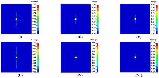
Figure 10.
Crack propagation under different in-situ stresses: (I) Px = 0, Py = 2; (II) Px = 0, Py = 4; (III) Px = 2, Py = 4; (IV) Px = 3, Py = 6; (V) Px = 2, Py = 2; (VI) Px = 4, Py = 4.

Figure 11.
Crack length under different in-situ stresses.
From the results of the comparative analysis of cases I and II, III and IV and V and VI, it can be seen that when λ = 0, the length of the vertical crack increases and the length of the horizontal crack decreases with the increase in Py; when λ = 0.5 and 1, the length of both the vertical crack and the horizontal crack decreases with the increase in Py. This indicates that with the increase in vertical pressure Py, the promotion and inhibition of crack propagation in different directions by in-situ stress become more and more obvious.
5. Experimental Study on HPAB on Coal Mass Specimen
5.1. Simulation Experiment Scheme of HPAB Coal Mass Specimen
A system for the HPAB experiment is established. The experimental system contains three subsystems: the gas pressure system, the high-pressure gas release control system and the data acquisition and analysis system, as shown in Figure 12. First, the air is compressed to the experimental design pressure by a gas booster system consisting of an air compressor and booster pump. Then, the compressed gas is stored in a high-pressure gasholder to ensure the required amount of gas for the HPAB. Finally, a control system consisting of a solenoid valve as well as a pressure gauge is used to release the high-pressure gas to impact the sample, while a data acquisition system collects the dynamic strain during the explosion. The HPAB coal experiments are conducted by the subject group [34].
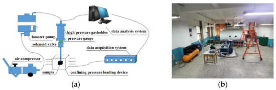
Figure 12.
The HPAB experimental system: (a) schematic diagram; (b) physical picture.
During the field collection and post-processing of the coal samples, secondary disturbance damage occurs inside the coal samples. In addition, the corresponding sensors need to be placed inside the specimen to obtain the strain waves induced by HPAB. This is difficult to achieve in the actual coal samples. Therefore, simulated coal samples are selected as the research sample to carry out the related experimental research work. The simulated coal sample used in the experiment is composed of basic materials and additive materials, which can ensure that the internal pore structure and physical and mechanical property parameters of the simulated coal sample are similar to those of the actual coal mass. The basic materials are used to control the structural strength of the simulated coal sample and consist mainly of cement, sand and water. The additive materials are used to control the micro-fractures, micro-cavities, structural surfaces and gases inside the simulated coal sample, mainly consisting of gypsum, perlite, blowing agents and mica. Therefore, the crack propagation mechanism of the simulated coal sample is in good agreement with the crack propagation mechanism of the actual coal mass, which is a good reference value for studying the crack propagation mechanism of the actual coal mass. In addition, based on the previous research work conducted by our research group in simulating the material selection and damage fracture mechanisms of coal [23,35,36], the material mass ratios and physico-mechanical parameters of the samples are obtained, as shown in Table 4. As can be seen in Figure 13a, the size of the simulated coal sample is 500 mm × 500 mm × 500 mm. A blasthole with a diameter of 20 mm and a length of 300 mm is reserved in the middle of the sample. The strain bricks are buried at four locations 50 mm, 150 mm, 250 mm and 300 mm from the blasthole. The strain brick is a simulated coal sample with a sensor used to collect strain waves, and its size is 20 mm × 20 mm × 20 mm. As shown in Figure 13b, the DH5922N dynamic signal test and analysis system is used to collect the strain wave induced by HPAB in the coal body.
Table 4.
The material mass ratio and physico-mechanical parameters of the sample.
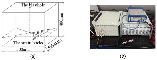
Figure 13.
Experimental instrument and monitoring point: (a) layout of measuring points; (b) DH5922N dynamic signal acquisition system.
5.2. Strain Wave and Crack Propagation in Coal Mass Specimen Induced by HPAB
Five simulated coal samples are selected for HPAB experiments in this paper, as shown in Figure 14. In the HPAB experiment, there are 20 measuring points in five simulated coal samples, of which 11 valid waveforms are acquired. However, nine of the waveforms are invalid due to damage to the strain gauges, burial of the strain bricks, etc. The data of monitoring points within the five simulated coal samples are shown in Table 5. In order to reduce the influence of strain gage on the strain wave test data, the average of the five experimental data is used as the final experimental result at the measurement point. The peak strains at each measurement point are 4904 με, 999 με, 327 με and 290 με, respectively, where some of the measured waveforms’ output with the DasView 2.0 software are shown in Figure 15.
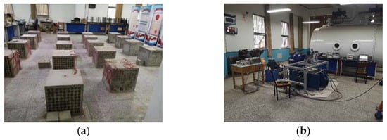
Figure 14.
HPAB experiments: (a) simulated coal samples; (b) laboratory experiment.
Table 5.
The peak strains at each measurement point.
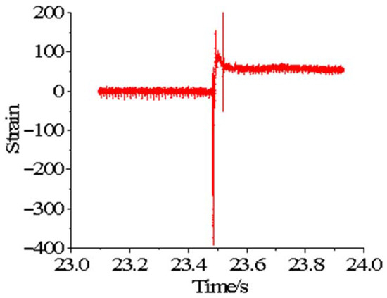
Figure 15.
Strain wave of coal mass specimen induced by HPAB.
As can be seen from Figure 15, the strain waveform induced by HPAB consists of two parts: the stress compressive phase and the stress tensile phase. When high-pressure air expansion is in the blasthole, the wall of the blasthole will first be impacted by high-pressure air. Then, a complete smooth stress waveform consisting of the compressive phase and the tension phase is formed under the effect of impact disturbance. Thus, it is evident from the complete stress waveform that the measurement point is first subjected to compressive stress and then to tensile stress.
There are two main stages in the crack propagation process during HPAB, namely the crack initiation and propagation stage induced by stress waves and the crack stable propagation stage induced by the duration of high-pressure gas. In the first stage of HPAB, the strain peaks of the monitored coal samples are larger and decay faster, while during the second stage of HPAB, their peaks are smaller and decay slower. Figure 16 shows the crack propagation of the coal mass specimen induced by HPAB, and the fractures are formed in the second stage of HPAB, which is the crack stable propagation stage. In the first stage of HPAB, the initial stress peak of the high-pressure gas is too small to cause crushing damage to the coal mass specimen. The coal mass specimen is mainly subjected to compressive stress, but the compressive strength of the specimen is much greater than the tensile strength, and the tangential tensile stress at the measurement point is greater than the tensile strength. Therefore, the internal coal mass in the near zone of the blasthole produces an initial radial crack under the action of the stress wave. As the distance from the blasthole increases, the peak stress wave decreases, and the stress wave cannot promote crack propagation. In the second stage of HPAB, the initial radial crack expands steadily from inside to outside under the action of high-pressure gas, and finally the coal sample is fractured.
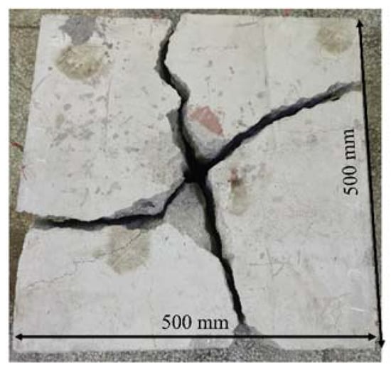
Figure 16.
Coal crack propagation induced by HPAB.
5.3. Comparison of Simulated Experiment and Numerical Simulation
In order to verify the reasonableness for the parameters of the RHT model, the experimental results and numerical simulation results are compared, and the crack propagation and the law of stress wave attenuation are shown in Figure 17 and Figure 18, respectively.
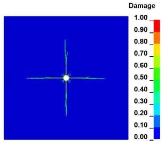
Figure 17.
Coal crack propagation obtained from numerical simulation.
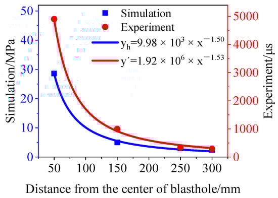
Figure 18.
Peak stress and strain attenuation fitting curve.
Figure 17 shows the numerical simulation result of coal crack propagation induced by HPAB. Comparing them with the experimental results shows that the number of cracks in the coal mass obtained from the numerical simulation is the same as the number of cracks obtained from the HPAB experiment, and the crack propagation pattern is also basically the same.
Figure 18 shows the fitted curves of the stresses obtained from the simulation and the strains obtained from the experiment at different measuring points. The experimental data in this paper are measured by the strain bricks and the DH5922N dynamic signal acquisition system. The stress decay curve is fitted from the simulated data and the strain decay curve is fitted from the experimental data, and the attenuation coefficients obtained from the numerical simulation and the HPAB experiment are 1.50 and 1.53, respectively. Stress and strain are basically linear. Therefore, when the attenuation coefficients of the two curves are essentially the same, it can be considered that the simulation results are close to the experimental results, which once again verifies the accuracy of the numerical model in this study.
6. Conclusions
In this paper, the crack propagation induced by HPAB was studied using the RHT model. The RHT model parameters were firstly determined and validated against HPAB experiments. Then, the crack propagation and stress wave attenuation patterns under the action of HPAB were investigated by comparing with equivalent explosive blasting. Finally, the effect of in-situ stress on crack propagation was investigated. Based on the simulation results, the following conclusions can be drawn.
(1) The crack propagation process under the action of HPAB is mainly divided into the crack initiation and propagation stage induced by the stress wave and the crack stable propagation stage induced by the duration of high-pressure gas. During the crack initiation and propagation stage, the coal damage variable D is larger, and the crack propagation is faster. However, during the crack stable propagation stage, the damage variable decreases, and the crack growth rate decreases.
(2) In the case of the same energy, the number of initial random cracks within the coal mass induced by HPAB is less compared to explosive blasting. Additionally, the peak value of the stress wave induced by high-pressure gas blasting is smaller, the decay rate is slower and the action time is longer, so the crack extension length is larger under the action of HPAB.
(3) Different in-situ stress conditions have different effects on the crack propagation of coal. When λ = 0, the in-situ stress can promote the propagation of vertical cracks but inhibit the propagation of horizontal cracks. When λ = 0.5 and 1, the in-situ stress inhibits the propagation of both horizontal and vertical cracks. Furthermore, with the increase of vertical pressure Py, the promotion and inhibition of crack propagation in different directions by in-situ stress becomes more and more obvious.
Author Contributions
For conceptualization, X.Y., C.W. and H.C.; methodology, C.W. and H.C.; formal analysis, C.W.; investigation, S.Y., H.W. and M.Y.; writing—original draft preparation, C.W.; writing—review and editing, X.Y. and H.C.; visualization, X.Y. and C.W. All authors have read and agreed to the published version of the manuscript.
Funding
This research was funded by the National Natural Science Foundation of China, (No. 51874123, 11542019), and Henan Research Program of Foundation and Advanced Technology (No. 162300410032).
Data Availability Statement
Acknowledgments
The authors thank Siyuan Zhu, Zhen Chen, and Zhiqiang Ren for their guidance on numerical simulation and HPAB experiment in this paper. The authors also thank the two anonymous reviewers for their remarks which improved the paper.
Conflicts of Interest
The authors declare no conflict of interest. The authors declare that they have no known competing financial interests or personal relationships that could appear to have influenced the work reported in this paper.
References
- Deng, J.; Qu, J.; Wang, Q. Research status and development direction in combustion and explosion of gas and coal dust in coal mine. Coal Mine Mod. 2014, 96–99. [Google Scholar] [CrossRef]
- Li, R.; Si, R.; Wang, l.; Jia, Q. Experimental study on starting condition and effect of active explosion proof for gas and coal dust explosion. J. China Coal Soc. 2021, 1–8. [Google Scholar] [CrossRef]
- Lin, B.Q.; Yan, F.Z.; Zhu, C.J.; Zhou, Y.; Zou, Q.L.; Guo, C.; Liu, T. Cross-borehole hydraulic slotting technique for preventing and controlling coal and gas outbursts during coal roadway excavation. J. Nat. Gas Sci. Eng. 2015, 26, 518–525. [Google Scholar] [CrossRef]
- Zhang, C.; Wang, E.; Xu, J.; Peng, S. A new method for coal and gas outburst prediction and prevention based on the fragmentation of ejected coal. Fuel 2021, 287, 119493. [Google Scholar] [CrossRef]
- Al-Anazi, H.A.; Pope, G.A.; Sharma, M.M.; Metcalfe, R.S. Laboratory measurements of condensate blocking and treatment for both low and high permeability rocks SPE Annual Technical Conference and Exhibition. In Proceedings of the SPE Annual Technical Conference and Exhibition, San Antonio, TX, USA, 29 September 2002. [Google Scholar] [CrossRef]
- Mahadevan, J.; Sharma, M.M.; Yortsos, Y.C. Capillary wicking in gas wells. In Proceedings of the SPE Annual Technical Conference and Exhibition, San Antonio, TX, USA, 24 September 2006. [Google Scholar]
- Zeng, F.; Li, C.; Sun, K.; Song, W.; Li, Z. Influence of gas explosion on permeability of coal body. Coal Geol. Explor. 2012, 40, 35–38. [Google Scholar]
- Wang, B.; Li, H.; Shao, Z.; Chen, S.; Li, X. Investigating the mechanism of rock fracturing induced by high-pressure gas blasting with a hybrid continuum-discontinuum method. Comput. Geotech. 2021, 140, 104445. [Google Scholar] [CrossRef]
- Zhu, Z.; Mohanty, B.; Xie, H. Numerical investigation of blasting-induced crack initiation and propagation in rocks. Int. J. Rock Mech. Min. Sci. 2007, 44, 412–424. [Google Scholar] [CrossRef]
- Hajibagherpour, A.R.; Mansouri, H.; Bahaaddini, M. Numerical modeling of the fractured zones around a blasthole. Comput. Geotech. 2020, 123, 103535. [Google Scholar] [CrossRef]
- Pu, C.; Yang, X.; Zhao, H.; Chen, Z.; Xiao, D. Numerical investigation on crack propagation and coalescence induced by dual-borehole blasting. Int. J. Impact Eng. 2021, 157, 103983. [Google Scholar] [CrossRef]
- Zhu, W.C.; Gai, D.; Wei, C.H.; Li, S.G. High-pressure air blasting experiments on concrete and implications for enhanced coal gas drainage. J. Nat. Gas Sci. Eng. 2016, 36, 1253–1263. [Google Scholar] [CrossRef] [Green Version]
- Zhao, J.; Zhang, Y.; Ranjith, P.G. Numerical simulation of blasting-induced fracture expansion in coal masses. Int. J. Rock Mech. Min. Sci. 2017, 100, 28–39. [Google Scholar] [CrossRef]
- Wang, Z.; Wang, H.; Wang, J.; Tian, N. Finite element analyses of constitutive models performance in the simulation of blast-induced rock cracks. Comput. Geotech. 2021, 135, 104172. [Google Scholar] [CrossRef]
- Ma, G.W.; An, X.M. Numerical simulation of blasting-induced rock fractures. Int. J. Rock Mech. Min. Sci. 2008, 45, 966–975. [Google Scholar] [CrossRef]
- Kutter, H.; Fairhurst, C. On the fracture process in blasting. Int. J. Rock Mech. Min. Sci. Geomech. Abstr. 1971, 8, 181–202. [Google Scholar] [CrossRef]
- Chu, H.; Yang, X.; Wang, C.; Liang, W. Study on the coal damage and fracture mechanism under multiple actions of blasting stress wave. Arab. J. Sci. Eng. 2021, 46, 10847–10854. [Google Scholar] [CrossRef]
- Yi, C.; Johansson, D.; Greberg, J. Effects of in-situ stresses on the fracturing of rock by blasting. Comput. Geotech. 2018, 104, 321–330. [Google Scholar] [CrossRef]
- Jayasinghe, L.B.; Shang, J.; Zhao, Z.; Goh, A.T.C. Numerical investigation into the blasting-induced damage characteristics of rocks considering the role of in-situ stresses and discontinuity persistence. Comput. Geotech. 2019, 116, 103207. [Google Scholar] [CrossRef]
- Wang, H.; Wang, Z.; Wang, J.; Wang, S.; Wang, H.; Yin, Y.; Li, F. Effect of confining pressure on damage accumulation of rock under repeated blast loading. Int. J. Impact Eng. 2021, 156, 103961. [Google Scholar] [CrossRef]
- Riedel, W.; Thoma, K.; Hiermaier, S. Penetration of reinforced concrete by BETA-B-500 numerical analysis using a new macroscopic concrete model for hydrocodes. In Proceedings of the Internationales Symposium, Interaction of the Effects of Munitions with Structures, Berlin/Strausberg, Germany, 3 May 1999. [Google Scholar]
- Borrvall, T.; Riedel, W. The RHT concrete model in LS-DYNA. In Proceedings of the 8th European LS-DYNA User Conference, Strasbourg, France, 23 May 2011. [Google Scholar]
- Chu, H.; Yang, X.; Yu, Y.; Liang, W. Test and research on similar material selection for coal blasting. Coal Sci. Technol. 2010, 38, 31–33. [Google Scholar]
- Malvar, L.J.; Crawford, J.E.; Wesevich, J.W.; Simons, D. A plasticity concrete material model for DYNA3D. Int. J. Impact Eng. 1997, 19, 847–873. [Google Scholar] [CrossRef]
- Li, H. The Study of the Rock RHT Model and to Determine the Values of Main Parameters; China University of Mining & Technology-Beijing: Beijing, China, 2016. [Google Scholar]
- Meyers, M.A. Dynamic Behavior of Materials; John Wiley & Sons: Manhattan, NY, USA, 1994. [Google Scholar]
- Ning, J.; Wang, C.; Ma, T. Explosion and Shock Dynamics; National Defense Industry Press: Beijing, China, 2010. [Google Scholar]
- Yang, M. Calculation and measurement of concrete impact insulation line. In Proceedings of the Material Penetration Symposium, Sanya, China, 1 December 2001. [Google Scholar]
- Holmquist, T.J.; Johnson, G.R. A computational constitutive model for concrete subjected to large strains, high strain rates, and high pressures. In Proceedings of the 14th International Symposium on Ballistics, Quebec City, QC, Canada, 26–29 September 1993. [Google Scholar]
- Zhao, J. Failure Mechanism of Hard Thick Coal under Various Types of Disturbance at the Front of Mining Face; China University of Mining & Technology-Beijing: Beijing, China, 2018. [Google Scholar]
- Huang, Y. Numerical Simulation of Rock Blasting Damage Evolution Based on HJC Constitutive Model; Hefei University of Technology: Hefei, China, 2020. [Google Scholar]
- Bi, C.; Wang, Z.; Shi, G.; Hao, S. The application of initial volume fraction method in explosion simulation. Eng. Blast. 2017, 23, 26–33+38. [Google Scholar]
- Li, W.; Di, G.; Wang, R. Analysis of a liquid CO2 tank explosion on a ship. Saf. Environ. Eng. 2010, 17, 95–98. [Google Scholar]
- Chu, H.; Yang, X.; Hou, A.; Yu, Y.; Liang, W. A simulation-based experimental study on explosion stress wave propagation and attenuation in coal. Explos. Shock Waves 2012, 32, 185–189. [Google Scholar]
- Chu, H.; Yang, X.; Yu, Y.; Liang, W. Study on the damage-fracture process and mechanism of blasting. J. Min. Saf. Eng. 2018, 35, 410–414. [Google Scholar]
- Chu, H.; Yang, X.; Liang, W.; Yu, Y. Simulation experimental study on coal blast mechanism. J. China Coal Soc. 2011, 36, 1451–1456. [Google Scholar]
Publisher’s Note: MDPI stays neutral with regard to jurisdictional claims in published maps and institutional affiliations. |
© 2022 by the authors. Licensee MDPI, Basel, Switzerland. This article is an open access article distributed under the terms and conditions of the Creative Commons Attribution (CC BY) license (https://creativecommons.org/licenses/by/4.0/).