1. Introduction
Submerged arc welding (SAW) consists of complex interactions of physical, electrical and chemical effects in the arc cavity [
1,
2]. In addition to the machine input selections of current, weld wire diameter, voltage, travel speed, current polarity and electrode (weld wire) extension, the flux chemistry and its chemical effects on the molten flux (slag) are important process input selections [
3,
4]. The welding flux performs several process functions: it forms a slag (molten flux) layer around the arc plasma to shield the arc from atmospheric oxygen and nitrogen, it limits weld metal hydrogen absorption from moisture, it limits arc energy losses from the arc to the environment by forming an opaque low conductivity slag boundary around the arc cavity, and it transfers alloying elements to the weld metal [
3,
4]. In carbon steel SAW, the weld pool manganese and silicon contents are controlled via flux formulation, in combination with the weld wire and base metal chemistries [
3,
4,
5]. Micro-alloying may also be performed via the molten flux; for example, the addition of Ti to the weld pool [
3,
4]. Significant quantities of fluoride minerals, typically CaF
2, are added to the flux to ensure that the flux melts at approximately 50 °C lower than the weld metal [
6]. For carbon steel, this translates to a relatively low flux melting temperature, as the steel solidus temperature is in the order of 1480 °C; therefore, the flux should be sufficiently molten at approximately 1400 °C. This temperature guideline appears to be selected to ensure that the slag solidifies after the weld pool steel has solidified [
6]. The maximum weld pool temperature has been reported as 2000 °C [
7,
8]. Due to this wide temperature range applied to the slag in SAW, the slag properties also change widely across this temperature range. The flux is also formulated to be a “short” or “long” slag, depending on the welding application [
9,
10]. Most fused fluxes form “short” slags since their compositions are selected close to the multi-component system’s eutectic composition [
10]. Consequently, the difference in the slag liquidus temperature and solidus temperature is small and the slag transitions over a small temperature interval from fluid to viscous [
9,
10,
11]. Most agglomerated fluxes form “long” slags with the opposite melt characteristics to a “short” slag [
11]. In addition to its role in setting the liquidus and solidus temperatures in the slag, CaF
2 is also used to set the process physico-chemical properties of the slag to enhance its process application. For example, the slag viscosity and surface tension are also influenced by CaF
2 as the F
− serves as network modifier anion [
12]. Several recent studies are available on SAW flux development, linking physico-chemical properties of the molten flux(slag) to flux input compositions via regression studies and fundamental slag structure studies, respectively [
13,
14]. However, these studies were not focused on the multi-component system of CaF
2-SiO
2-Al
2O
3-MgO, relevant to this study. Furthermore, even though fluoride-based fluxes are used in the continuous casting of steel and electro slag refining (ESR), the target compositions in these types of fluxes differ substantially from the flux composition ranges as applied in SAW with either much lower or much higher CaF
2 content and high CaO contents [
15,
16].
Another critical physical parameter is slag detachability from the weld metal. Good slag detachability is required to ensure high welding productivity because no extra time should be used to mechanically remove any slag sticking to the weld metal. Additionally, in multi-pass welding, an easily detachable slag is critical to prevent any contamination of subsequent weld runs due to remnant slag added into the weld pool [
17]. Fundamental reasons given for good slag detachability vary from ensuring a large difference in thermal expansion between the solid slag and weld metal; to preventing the formation of excessive quantities of high-melting-point phases such as spinel (MgO·Al
2O
3), Cr
2O
3 or perovskite (CaTiO
3); to the prevention of formation of a chemical bond via interlayer formation between the slag and weld metal; and to ensuring that a low-strength slag is formed from the molten flux [
3,
7,
17,
18,
19,
20]. Conflicting findings have been reported; for example, in one study, perovskite in the slag was found to be detrimental to slag detachability [
20], and in another, perovskite was recommended to aid in slag detachability due to its higher coefficient of thermal expansion, as compared with the underlying high Ni–Cr alloy weld metal [
21]. In some instances, a small quantity of solid phase is added to improve slag detachability. For example, up to 2 mass% ZrO
2 is added to basic fluxes to compensate for their similar thermal expansion coefficient to that of the steel weld metal [
3]. Spinel can also be used to induce micro-stresses in the glass phase to enhance slag detachability due to its different thermal expansion coefficient to the solidified glass phase [
9]. It is well stated that the application of the weld flux in the particular welding set-up must be investigated in the welding tests to make any conclusions on slag detachability because the interaction of chemical and welding parameters in the process determines slag detachability [
18].
The addition of CaF
2 in the flux formulation is also used to control the weld metal ppm O and limit hydrogen pick-up into the weld metal. Although the weld pool and arc cavity are isolated from the atmosphere, oxygen is added into the weld pool via the dissociation of oxides in the flux. Oxides decompose in the arc plasma due to high temperatures, in the order of 2000 °C to 2500 °C [
22,
23]. Oxygen is adsorbed onto molten weld wire droplets in the arc plasma and transferred into the weld pool via the molten wire droplets [
24,
25]. The rank of oxide stability in the arc plasma was measured from least stable to most stable as MnO and SiO
2, MgO, Al
2O
3, TiO
2, Na
2O, K
2O, and CaO [
24]. The effect of fluorides in the flux is to lower the P
O2 in the arc cavity by forming fluorine-based compounds via reactions similar to reaction (1) between SiO
2 and CaF
2 [
26,
27]. Similarly, the P
H2 is lowered to limit hydrogen pick-up into the weld metal [
28,
29]. Hydrogen pick-up in the weld pool is also limited by reactions of water vapour and CaF
2, according to reaction (2), and by formulating the flux chemistry for increased hydrogen dissolution capacity [
27,
28,
29].
The empirically determined trend of flux basicity (BI) vs. ppm O in the weld metal is generally used to design fluxes for the target oxygen content in the weld metal. The BI expression is shown in Equation (3) in mass% values [
30].
By ensuring that the flux solidus temperature is lower than the weld pool steel solidus temperature, maximum time is allowed for chemical interaction between the flux and the underlying weld pool steel. Increased reaction time between the weld pool steel and covering slag is important to ensure that oxide inclusions have more time to float out of the weld pool steel, to the slag–weld pool interface to ensure clean steel in the weld metal [
31]. The flux chemical composition is usually not changed significantly during slag formation in SAW, although some FeO is added due to the oxidation of steel Fe to FeO [
22,
32,
33,
34,
35]. In our recent studies, aluminium powder was applied in the SAW process as a de-oxidiser element to increase metal powder alloying in the weld pool [
36,
37,
38,
39]. The added aluminium powder significantly changed the flux chemistry via reduction reactions of oxides of SiO
2 and MnO, similar to reaction (4) for MnO reduction by aluminium. The increased Al
2O
3 content in the slag has important effects on the physico-chemical properties of the slag.
The objective of this study was to investigate slag phase chemistry modifications due to the application of aluminium powder in the alloying of carbon steel weld metal and use this information to interpret slag detachability differences. The post-weld slag chemistry is discussed with the aid of calculations in FactSage 7.3 thermochemical software, using the FToxid database [
40,
41].
2. Materials and Methods
SAW welding tests were made as bead-on-plate runs onto steel plates of 350 mm in length, 12 mm plate thickness and 300 mm plate width. Weld heat input was 2.0 kJ/mm (500 A, 28 V, 42 cm/min) welded DCEP (direct current electrode-positive) with a 3.2 mm diameter wire. Structural steel grade EN 10025-2 was used as a base plate material. The chemical analyses of the base plate and weld wire are summarised in
Table 1. Major element levels in the weld wire analysis are from the supplier’s specification sheet, supplied by Afrox Ltd., Johannesburg, South Africa. The base plate steel was analysed by optical emission spectroscopy (OES), model SpectroMax XF, 2018, from SPECTRO Analytical Instruments GmbH, Kleve, Germany. The oxygen content in the base plate and weld wire was analysed by combustion method.
Commercial agglomerated flux of the composition presented in
Table 2 was used in the welding experiments, following a previous detailed study on a selection of commercial agglomerated fluxes [
42]. This is an aluminate basic flux (basicity index (BI) = 1.4) and was extensively analysed as reported previously [
42]. The main consideration in the selection of this flux is its likely thermodynamic stability in the presence of aluminium powder as a de-oxidiser element. The metal powder additions used as additions in the SAW tests were sourced as Al (99.7% Al) supplied by Sigma-Aldrich, St. Louis, MO, USA, Ti (99.5% Ti) supplied by PLS Technik GmbH & Co., Niedernberg, Germany, and Cu (99.8% Cu) supplied by Goodfellow, Hintingdon, UK.
The welded plate was sectioned to remove cross-section samples of the weld metal for major element analyses by OES, and total oxygen content analyses were performed by the combustion method. Due to higher concentrations of Ti and Al in the weld metal, compared with low-carbon steel, the %Al and %Ti were analysed by ICP-OES (inductively coupled plasma optical emission spectrometry). The weld metal sample was digested by a three-acid digestion method, using HNO
3, HCl and HF. The weld metal results confirmed significant alloying of the weld metal from the added metal powders, and also increased %Mn and %Si in the weld metal due to the aluminothermic reduction of MnO and SiO
2 from the flux [
36,
38]. Due to significant changes measured in the bulk compositions of post-weld slags, compared with the original flux chemistry, these changes are quantified and interpreted in this study. Furthermore, slag removal from MP1 and MP3 welds, made with metal powder additions were difficult, requiring light mechanical impact. In comparison, the slag from the BC weld, welded in the absence of metal powder additions, effectively self-removed without the requirement of any mechanical impact.
The post-weld slag bulk chemistry and mineralogy were analysed. Slag bulk chemistry was analysed by inductively coupled plasma optical emission spectrometry (ICP-OES). Sample digestion in HCl and HF was used for major element analysis, and sample fusion in Na2O2 and Na2CO3, with subsequent digestion in HCl was used for minor element analysis. The slag F-content was analysed by the titration method, following sample digestion in HClO4. Slag crystallinity was analysed by XRD (X-ray diffraction) analyses. The XRD samples were prepared according to the standardised Panalytical backloading system, which provides a nearly random distribution of the particles. The samples were analysed using a PANalytical X’Pert Pro powder diffractometer (Malvern Panalytical, Almelo, The Netherlands) in θ–θ configuration with an X’Celerator detector and variable divergence and fixed receiving slits with Fe-filtered Co–Kα radiation (λ = 1.789 Å). The mineralogy was determined by selecting the best-fitting pattern from the ICSD database to the measured diffraction pattern, using X’Pert Highscore plus software (version 4.9).
Phase chemistry of the slag phases in the sample polished sections were assessed by SEM (scanning electron microscopy). Phase chemistry analysis was measured by using a Zeiss crossbeam 540 FEG (field emission gun) scanning electron microscope. EDX (energy dispersive X-ray) analyses were performed at 20 kV and 5.6 mm working distance. The SEM analyses were performed at the edge of the slag surface which was in contact with the weld metal during welding. Therefore, comparison of the slag SEM analyses at this interface to the bulk slag chemistry should show up any major composition differences that occurred due to the welding process.
3. Results
The post-weld slag bulk chemistry in
Table 3 illustrates significant chemistry changes in the MP1 and MP3 slags when compared with the Base Case (BC) slag. These changes are due to the addition of metal powder to the weld pool, as compared with the Base Case (BC) slag formed in the absence of metal powder additions [
36,
37,
38,
39]. Mainly, MnO and SiO
2 decreased and Al
2O
3 and TiO
2 increased, as shown in the
Table 3 analyses for MP1 and MP3, relative to the BC slag analysis. The increase in Al
2O
3 is due to the use of aluminium metal powder as a de-oxidiser metal in the weld pool, and due to the aluminothermic reduction of MnO and SiO
2 [
36,
38]. The increased TiO
2 content is due to the oxidation of Ti to its oxide. Although some Cu was analysed in the MP3 bulk slag, the presence of copper in the slag SEM phase analysis was not confirmed. Therefore, the Cu analysed in the bulk slag chemistry was most likely due to metallic Cu loss to the slag.
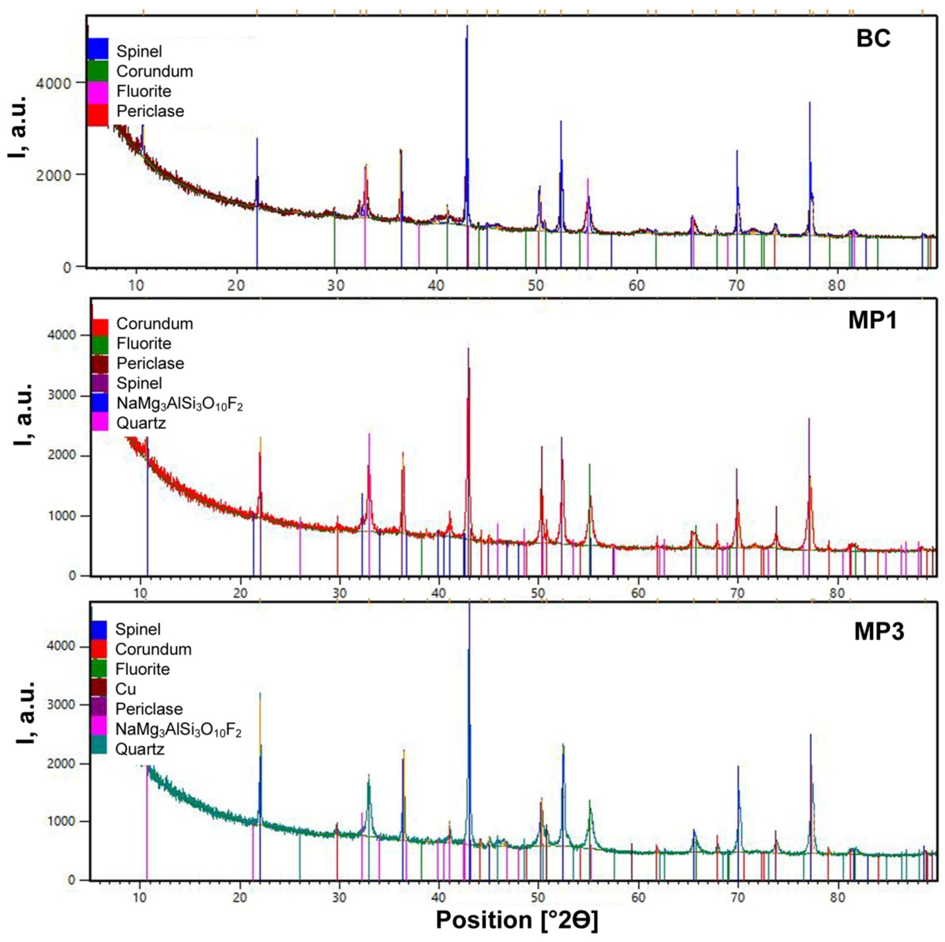
Figure 1 illustrates that the XRD analyses identified similar crystalline phases in all the post-weld slags, namely, spinel (MgAl
2O
4), corundum (Al
2O
3), fluorite (CaF
2), periclase (MgO), quartz (SiO
2) and the NaMg
3AlSi
3O
10F
2 oxy-fluoride phase. The characteristic hump in the count rate values at low 2Θ values indicates the presence of amorphous phase.
Figure 2,
Figure 3,
Figure 4,
Figure 5 and
Figure 6 display the typical phase assembly in BSE (backscattered electron) images in each post-weld slag sample, and the associated phase compositions analysed by SEM. Although the BC slag sample was previously investigated in detail, a new area of analysis is shown in
Figure 2 to show the unaltered molten flux for comparison with the altered slags from the MP1 and MP3 tests shown in
Figure 3,
Figure 4,
Figure 5 and
Figure 6 [
42].
The presence of spinel crystals in the Al-Mg-Ca-F-Si-Ti-Mn-Fe-K-Na-O oxy-fluoride matrix glass is confirmed in the analyses summarised in
Table 4, for the marked phase areas in
Figure 2. The spinel crystals are close to 20 µm in cross-sectional dimension. Feathery wisps appear in the matrix glass, such as in position 7 in
Figure 2.
Figure 3 shows a BSE image of an area in the MP1 slag. The phase areas consist of Ti-containing spinel crystals in the oxy-fluoride glass matrix phase. The presence of a large cluster of spinel crystals at the top left-hand edge of the sample is clear, as seen from the octahedral crystalline shape of the spinel crystals. The analyses in
Table 5 confirm the pick-up of Ti in the spinel and matrix glass phases, compared with the BC phase analyses in
Table 4. Some variability is seen in the glass phase fluoride content in
Table 5. Some variability in the fluoride contents in similar samples was reported for the phase area analyses in agglomerated flux material of the MgO-Al
2O
3-SiO
2-CaF
2 system, melted under laboratory conditions [
43].
Figure 4a shows the BSE image of a smaller area in the MP1 slag, and
Figure 4b shows EDX mapping of this area. It is clear from the data displayed in
Figure 4b that the larger angular crystals are the spinel crystals embedded in a matrix of Al-Mg-Ca-F-Si-Ti-Mn-Fe-K-Na-O oxy-fluoride glass phase from which Al-Mg-Si-Ti-Mn-O containing small phase areas appear to be exsolved upon cooling. Interestingly, Ti is distributed across all phases, in agreement with the phase analyses in
Table 5. However, it is seen from the EDX maps that the distribution of Ti is not uniform, because Ti appears to be present in higher concentrations at the outer edges of the large spinel crystals, metal areas and at points inside the exsolved Al-Mg-Si-Ti-Mn-O phase areas. The spinel crystals are typically 40 µm in cross-sectional dimension.
Figure 5 shows the phase assemblage of an area in the MP3 slag. The phases in the MP3 slag are similar to those in the MP1 slag, consisting of spinel crystals set in the oxy-fluoride glass matrix phase. The phases in
Figure 5 contain less Ti than the phases in
Figure 3, although Ti is incorporated into both the oxy-fluoride glass matrix and spinel phases in slags MP1 and MP3. It is possible that some of the Ti analysed in the bulk slag composition in
Table 3 represent metallic Ti. Comparison of the phase chemistries at positions 2 and 3 in
Figure 5 and
Table 6 indicates the modification of pure Al
2O
3 to spinel (MgAl
2O
4).
Figure 6a shows the BSE image of a smaller area in
Figure 5, and
Figure 6b shows EDX mapping of this area. The element distribution in
Figure 6b corresponds to that in
Figure 4b as angular spinel crystals embedded in the Al-Mg-Ca-F-Si-Ti-Mn-Fe-K-Na-O oxy-fluoride glass phase matrix, with small phase areas of Al-Mg-Si-Ti-Mn-O phase exsolved upon cooling. Titanium is distributed across all phases, with higher concentrations at the edges of the large spinel crystals and as points inside the exsolved Al-Mg-Si-Ti-Mn-O phase areas. The spinel crystals are typically of 25 µm in cross-sectional dimension.
4. Discussion
The solid crystalline phases present in the polished sections displayed in
Figure 2,
Figure 3,
Figure 4,
Figure 5 and
Figure 6 may have formed as cooling phases as the post-weld slag cooled down from the high welding temperatures close to 2000 °C in the weld pool to room temperature [
7,
8]. This possibility was investigated by calculating the phase solidification curves for each slag composition in
Table 3, using the Equilib module in FactSage 7.3 thermochemical software, and selecting the FToxid database [
40,
41]. Although there are no multi-component phase diagrams of the system of interest in this study, the FactSage thermochemical software calculation outputs for the CaO-SiO
2-MgO-Al
2O
3-CaF
2 system were confirmed to be accurate compared with some equilibrated slag samples in a previous study [
44]. Therefore, the FactSage calculations in this study are used with confidence as the basis of the expanded multi-component system relevant to our study. In addition, there are a few published studies available on the phase chemistry and physico-chemical properties of fluxes in the system of Al
2O
3-MgO-CaF
2-Na
2O-K
2O-Fe
2O
3 [
9,
10,
45]. These studies confirmed that the MgO and Al
2O
3 in the flux reacted to form spinel upon heating of the flux, even at temperatures as low as 700–800 °C, and more easily at 1200 °C to 1500 °C. Spinel phase formation occurred even when the flux glass phase was only partially molten at 1200 °C [
9]. The authors confirmed that the lighter spinel phase floated from the bulk slag. Furthermore, the authors point out that the differences in thermal expansion coefficients of the spinel phase and the liquid slag phase may be used to induce micro-stresses in the slag to ensure good separation between the slag and the underlying metal [
9]. This is an important design aspect in the development of welding fluxes because it ensures good bead shape, surface finish and high welding productivity [
17].
The solidification curves in
Figure 7a–d are in general agreement with the reported high-temperature-phase chemistry in this flux system, namely, the presence of a liquid slag phase and solid spinel crystallites [
9,
10]. The solidification curve calculations predict that the flux mixture was completely liquid at the weld pool temperature reported in the literature, 2000 °C [
7,
8]. Upon cooling, spinel precipitated as the primary solidification phase. Due to the increased alumina content in the modified MP1 and MP3 slags, the percentage spinel phase is increased to double that of the BC slag at 1400 °C. Clearly the increased alumina content in the MP1 and MP3 slags would significantly increase the two-phase slag viscosity, compared with the unaltered BC slag viscosity [
9,
45]. As indicated before, due to the exponential increase in slag viscosity with increased solid phase proportion, even slight increases in the proportion of spinel phase in the slag result in a drastic increase in slag viscosity [
10]. Slag viscosity is double that of the CaF
2 matrix phase with every 10 mass% increase in solid phase [
46].
Figure 7d shows the liquid glass curves from
Figure 7a–c for easier comparisons. The curves illustrate that although the slag liquidus temperatures are similar at 1682 °C, 1730 °C and 1670 °C, the precipitation phase formation sequence sets these slags apart. For example, at 1400 °C the BC slag contains 25% spinel phase, compared with 38–39% spinel in the MP1 and MP3 slag. Increased spinel content in the MP1 and MP3 slags is due to the higher quantity of Al
2O
3 present in the MP1 and MP3 slags, in combination with fewer glass matrix formation compounds of SiO
2 and MnO from aluminothermic reduction of the slag. Furthermore, it appears that at the lower temperatures close to 1000 °C, the higher TiO
2 in MP3 slag somewhat compensates for the increased spinel phase formation due to higher %Al
2O
3 and lower %SiO
2 and %CaF
2 contained, as compared with the MP1 slag.
Another aspect in the investigation of slag detachability is the difference in solidification temperatures of the slag and the weld metal.
Table 7 summarises the weld metal alloy solidus temperatures and the spinel proportions in each slag at 1400 °C and at the weld pool solidus temperature, as calculated in FactSage 7.3. The value of 1400 °C is considered with reference to the flux design guideline that the slag should be melting at 50 °C below the solidus temperature of carbon steel [
6]. However, MP1 and MP3 weld metals have lower solidus temperatures than carbon steel resulting in increased spinel content in the MP1 and MP3 slags at the weld metal solidus temperatures, of approximately 40% spinel phase compared with only 23% spinel phase in the BC slag. Therefore, it is conceivable that the MP1 and MP3 weld bead surface morphology is solidified as rough surfaces due to the high spinel content as the cause of high viscosity slags at the weld pool–slag interface. The result is mechanical fixation of the slag to the rough weld bead surface, identified previously for different welding conditions [
18].
As pointed out above, the spinel phase grows from oxide slag according to the parabolic rate law at higher temperatures, in the order of 1400 °C [
10,
47].
Figure 8 shows the growth rate relationship reported in the literature applied here to calculate the time required for a spinel crystal to grow to a specific size at different temperatures. At 1700 °C, close to the liquidus temperatures of slags BC, MP1 and MP3, the rate equation predicts that a 10 μm spinel crystal can crystallise and grow from the molten glass phase in 2.0 s and a 20 μm crystal in 7.9 s. The BC weld metal solidification time was calculated to be about four seconds, using the weld ripple lag distance and travel speed [
32,
33]. In comparison, the typical spinel crystal sizes observed in the BSE images of
Figure 2,
Figure 4 and
Figure 6 are 20 μm, 40 μm and 25 μm in the BC, MP1 and MP3 slags, respectively. These observations are in agreement with the formation of the larger spinel crystals observed in MP1 slag (40 μm) from the enhanced process whereby Al
2O
3 is formed in aluminothermic reduction, and not only from spinel formation from the matrix glass phase.
The relative phase changes in the slags are further analysed in the following pseudo-ternary phase diagrams to chart possible improvements in flux formulations to compensate for the increased Al
2O
3 and decreased SiO
2 and MnO in the slag, when using aluminium as deoxidiser element in SAW. The pseudo-ternary phase diagrams in the CaF
2-SiO
2-Al
2O
3-MgO-TiO
2-FeO system were calculated in the Phase Diagram module of FactSage 7.3, by selecting the FToxid database. These diagrams are not as precise in their thermochemical phase boundaries as the curves in
Figure 7, because here only the approximate compositions in terms of the major composition compounds are considered. However, in
Figure 7, the precise compositions as shown in
Table 3 are used as inputs to the calculations.
Figure 9a–c displays the pseudo-ternary diagrams at 1400 °C for the fixed %SiO
2, %TiO
2 and %FeO for each post-weld slag composition, and each post-weld slag composition is indicated as a filled marker. The %CaO and %MnO were not specified because these low-percentage compounds may be easily incorporated into the oxy-fluoride matrix phase, as displayed in
Figure 4 and
Figure 6.
Figure 9a–c shows that the 1400 °C liquidus boundary is moved little with changes in %SiO
2 and %TiO
2. The phase field of interest, the (liquid + spinel) phase field, is somewhat enlarged as the (liquid + olivine + spinel) phase field shrinks with increased %TiO
2.
By increasing the %CaF
2 in the starting flux, the slag composition may be adjusted to accommodate the additional spinel from the aluminothermic reduction process. This is illustrated in
Figure 10 in which the BC flux composition was adjusted to attain approximately 20% spinel at 1250 °C. These adjustments in %CaF
2 should sufficiently compensate for the increase in percentage Al
2O
3 in the slag from aluminothermic reduction, to prevent viscosity and slag detachability problems caused by excessive spinel formation at the lowered alloy steel solidus temperatures.
Therefore, the flux should be formulated to manage the slag phase proportions of matrix oxy-fluoride glass phase to spinel crystals. Increasing the proportion of matrix oxy-fluoride glass phase in the slag will ensure a fluid slag at lower temperatures to improve slag detachability. As highlighted in previous studies, the flux CaF
2 content should be increased to increase the proportion glass matrix phase in the slag, but also to reduce the size and increase the dispersion of spinel crystals formed upon solidification of the slag [
8,
43].


