Abstract
In this study, the compression failure test of rock with prefabricated fractures under different true triaxial conditions is carried out by using the true triaxial electro-hydraulic servo test system. The traditional large number of fracture laws with prefabricated fissures are merged and attributed to the induction of intermediate principal stress. The test results show that the direction of has a significant effect on the deformation characteristics of the prefabricated fractured rock. The internal crack expansion direction is more random and the crack distribution is more extensive and complex under uniaxial and conventional triaxial conditions. Under biaxial and true triaxial conditions, the crack propagation direction is clearly along the direction. This shows that the development process of internal cracks in rocks tend to the direction of . Further, the failure mechanism of rock with prefabricated cracks is analyzed based on theory. It is found that the intermediate principal stress direction plays a very important role in inducing the direction of rock crack propagation. According to the unified idea, the fracture analysis of fractured rock is summed up as true triaxial theory, and the results are consistent with the experimental results. This provides a new perspective for the study of rock fracture mechanics, and provides an important basis for the analysis of surrounding rock fracture mechanism of underground engineering.
1. Introduction
Mining, underground gas storage, waste disposal and other fields are important national infrastructure projects [1]. It is extremely important to evaluate the stability of rock masses during underground engineering activity and provide support countermeasures to ensure safe underground construction and stable operation [2]. The mechanical properties of a rock mass are important parameters in underground rock engineering design and stability analysis [3]. Long-term geological processes cause a variety of defects (such as cracks, joints, etc.) in rocks [4], which often affect the original mechanical properties of the rock (intact rock) to varying degrees [5]. Excavation activity during underground engineering [6] causes cracks to initiate and expand along preexisting defects (or nearby areas) in rock masses [7], and this can lead to disasters of rock mass failure and instability to occur frequently [8]. Therefore, it is essential to correctly understand the mechanical behavior and failure process of fractured rock masses to better evaluate rock mass stability during underground engineering and provide guidance for safe engineering construction [9].
Many scholars have performed many uniaxial compression tests to study the macroscopic mechanical behavior and fracture propagation of fractured rock. Combined with digital image processing [10], acoustic emission [11] and other technical means, the influence of different types of cracks and different geometric parameters of prefabricated cracks [12] on the deformation, strength and crack propagation mode [13] of samples has been analyzed. Pakzad [14], Zhou [15] and other scholars carried out in-depth studies on the uniaxial loading failure of prefabricated fractured rocks and obtained the evolution law of rock fracture extension. Haeri et al. [16] studied the crack aggregation and fracture path under uniaxial compression. Bastola et al. [17] analyzed the progressive evolution of damage near the crack tip during uniaxial compression of multi-cracked rocks. The sprouting and extension of fractures within rocks are not only related to their structural characteristics but also closely related to the stress environment in which the rocks are located [18].
Some scholars have performed biaxial compression tests (based on uniaxial compression tests) on prefabricated fractured rock samples [19] to study the influence of different confining pressures on fracture propagation [20]. Manouchehrian [21] analyzed in detail the effect of biaxial confining pressure on the propagation mechanism of prefabricated fractures. Wang et al. [22] conducted biaxial compression tests on rock materials containing prefabricated fissures and found that the frequency of secondary shear between the fissured rock bridges increased with the increase in the lateral envelope pressure. Liu et al. [23] found that the confining pressure gradually inhibits the initiation of wing cracks under biaxial compression conditions.
In the above studies, the prefabricated crack is abstracted as a crack existing in a simple one-dimensional or two-dimensional stress environment [24], which produces tensile, shear, and composite modes after the application of external force, to describe the failure mode of the fractured rock [25]. Two-dimensional stress tests explain the mechanism of simple crack propagation and the failure mode of fractured rock, but in practical engineering, fracture propagation and evolution occur in a three-dimensional stress environment [26]. Therefore, some scholars have experimentally studied the failure of rocks with prefabricated cracks under conventional triaxial stress environments [27]. Combining different numerical calculation methods, Lisjak et al. [28] summarized in detail the development law of fracture propagation in rocks with prefabricated fractures under different triaxial stress environments. Gunarathna et al. [29] studied the laws of crack initiation, propagation and coalescence of fractured granite under triaxial compression. Yang et al. [30] studied the deformation, strength characteristics and fracture mode of specimens with prefabricated cracks under different conventional triaxial confining pressures.
By studying the rupture characteristics of rocks containing prefabricated fractures under conventional triaxial stress environments, scholars have shed much light on crack initiation and extension [31]. The results of these studies have significantly helped in understanding the mechanism of damage to rocks under three-dimensional stress environments [32]. However, without considering the influence of the intermediate principal stress, the conventional triaxial test cannot truly represent the actual stress state of a sub-surface rock mass [33]. In actual underground engineering, a rock mass often exists in a true three-dimensional stress environment [34]. The crack initiation and propagation characteristics in a rock mass under this true triaxial stress condition will be different from the test results obtained from conventional triaxial experiments [35]. Therefore, studies on rock fracture extension and mechanism under true triaxial stress conditions will provide more practical guidance for stable and safe underground engineering design and development [36].
In fact, the main difference between the true triaxial and the conventional triaxial stress environments is that the former takes into account the intermediate principal stress [37]. Many scholars have gradually realized that the intermediate principal stress has a greater influence on the mechanical behavior [38] and damage characteristics [39] of rocks by conducting true triaxial experimental studies [40]. However, the specific effect of the intermediate principal stress on crack development is not clear. So far, there have been few experimental studies subjecting rock specimens with prefabricated crack to true triaxial compression. In fact, uniaxial, biaxial and conventional triaxial compression are all special true triaxial stresses, which are unified as the true triaxial in this study with the unified idea of analyzing the important role played by the intermediate principal stresses from the perspective of its role on the evolution of internal cracks in rocks.
2. Experimental Methodology
2.1. Specimen Preparation
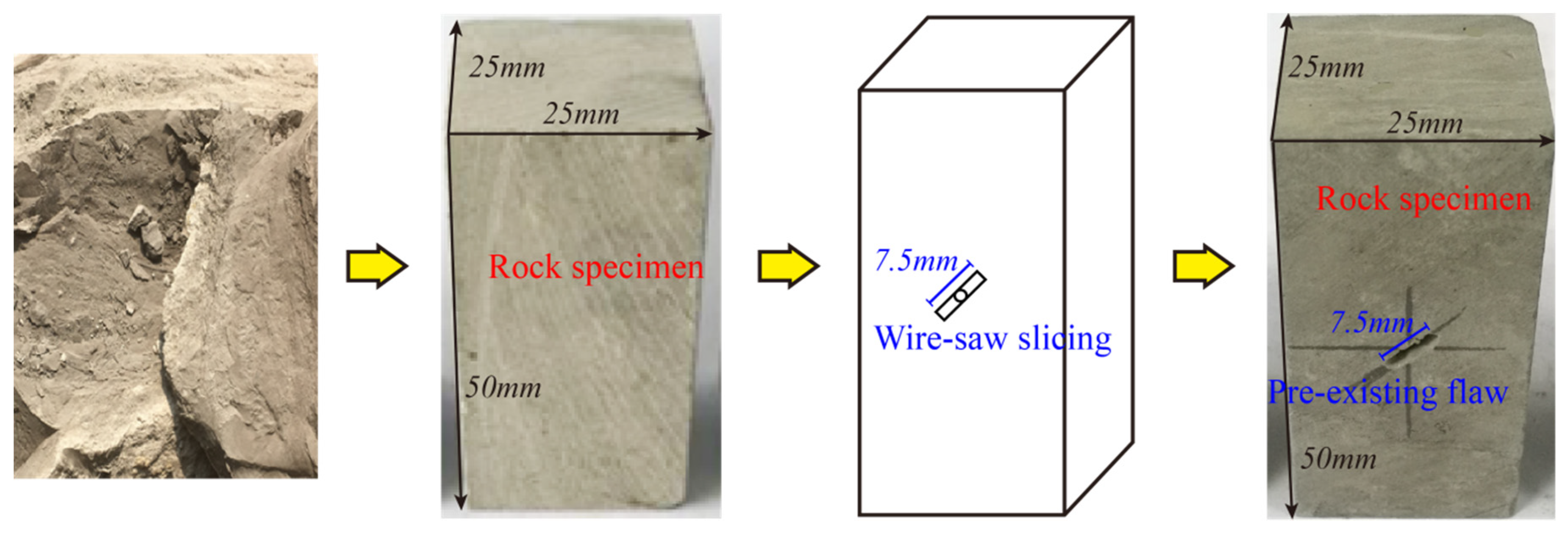
The specimens used in this study are mudstones selected from the Ordos region, Inner Mongolia, China. The mudstone has no visible defects, is gray in the natural state, soft in texture with an average density of about 2710 kg/m3, dense in structure but poor in cementation and easily disintegrates when exposed to water or moist air. The intact mudstone blocks collected in the field were transported to the laboratory for preparing prefabricated fracture specimens. First, the mudstone block was made into cuboid specimens with a size of 25 mm × 25 mm × 50 mm by anhydrous cutting technology (prevention of softening and disintegration of mudstone caused by water). The surface of the cutting sample was carefully grinded by a grinding machine to make the surface smooth and parallel to each other. On the basis of the prepared complete cuboid specimen, a through fracture was artificially prefabricated by the method of “Wire-saw sliding”. The specific steps are as follows: (i) In the center position perpendicular to the front surface of the specimen, a hole with a diameter of 2 mm through the front and rear surfaces of the specimen is prefabricated using a micro-gold rigid drill. (ii) A wire saw rope with a diameter of 1 mm was cut along both sides of the prefabricated hole by wire saw cutting technology. Finally, a through prefabricated fracture with a length of 7.5 mm, an opening of 2 mm and a fracture dip angle of 45° in the horizontal direction were formed (Figure 1).

Figure 1.
Preparation of mudstone specimens containing a pre-existing flaw.
2.2. Testing Procedure
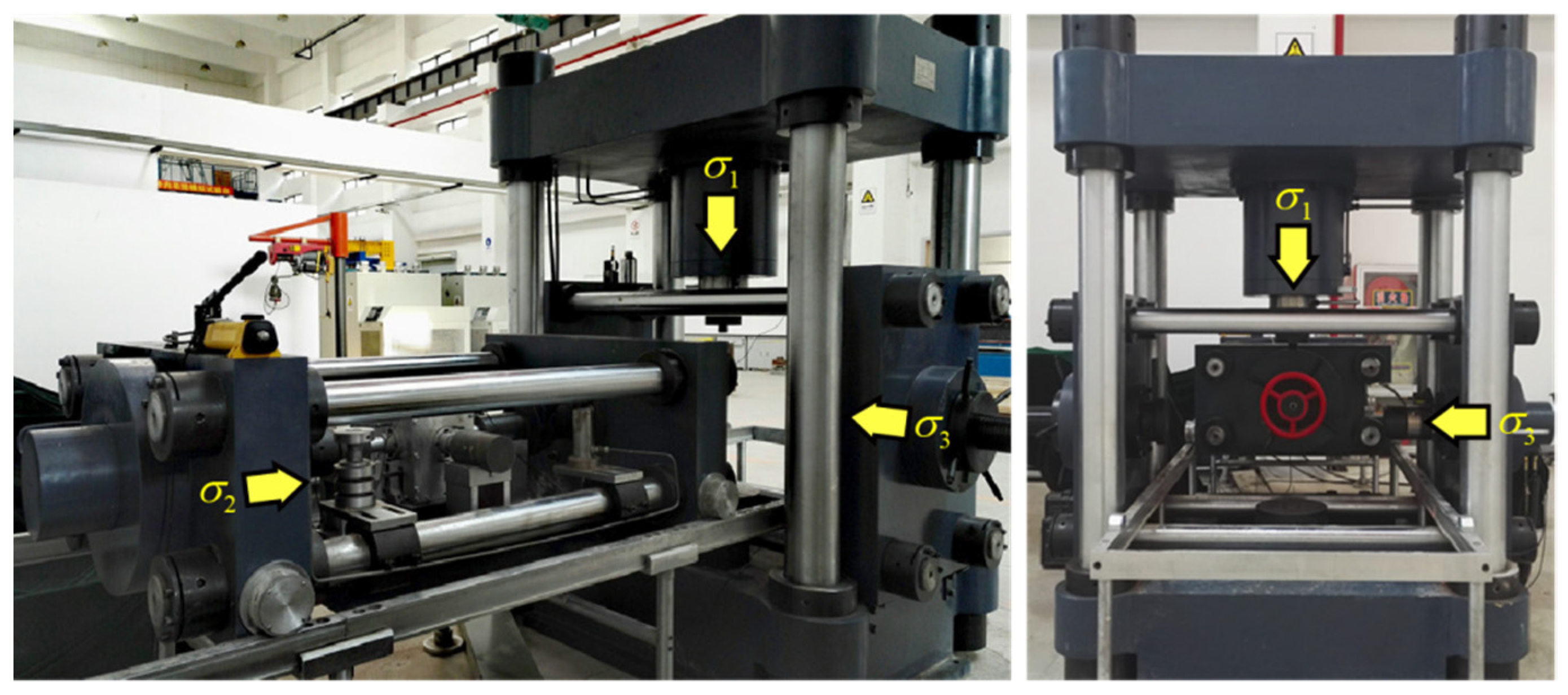
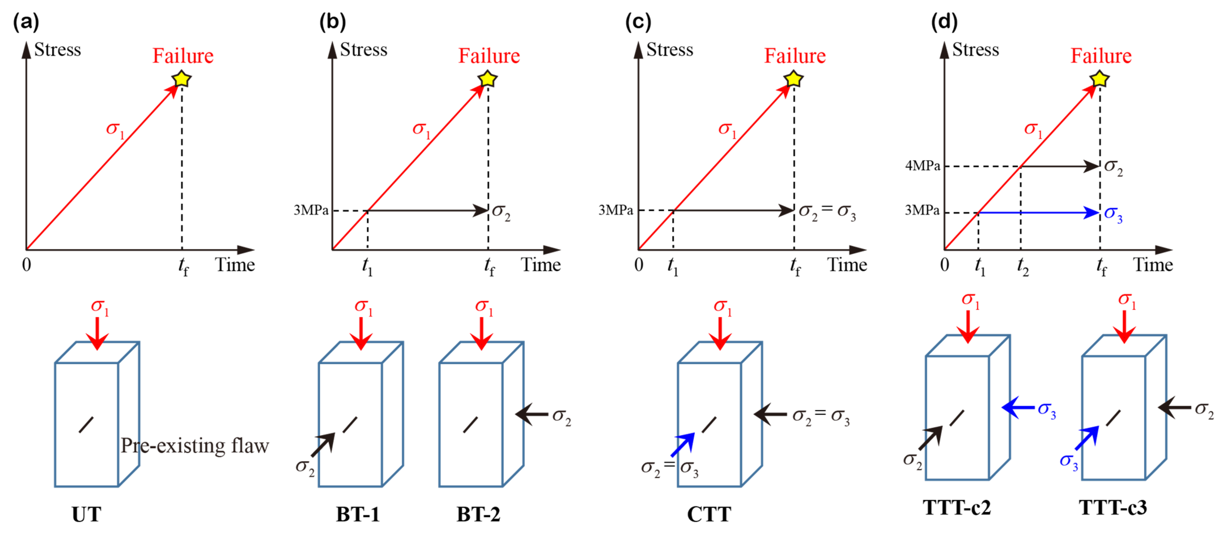
A true triaxial electro-hydraulic servo loading test system [41] was used in the tests; it mainly consists of a three-dimensional servo control loading system and a true triaxial stress cell (Figure 2). To investigate the effect of the intermediate principal stress on the evolution of fracture extension in the rock, uniaxial tests (UT), biaxial tests (BT), conventional triaxial tests (CTT) and true triaxial tests (TTT) were conducted in this study. There are 6 groups of tests containing prefabricated crack and 1 group of true triaxial intact rock test (TTT-Intact), and 3 specimens are used for each group (Figure 3). The test operations are similar, as shown in Figure 2 and Table 1. First, the specimen was subject to the predetermined confining pressure at the rate of 0.1 MPa/s according to the load control mode, and then the axial stress was applied to the specimen at a loading rate of 0.002 mm/s according to the displacement loading mode until the specimen failed. It should be noted that the biaxial loading test includes two cases: (1) the penetration direction of the prefabricated cracks is parallel to (BT-1); (2) the penetration direction of the prefabricated cracks is perpendicular to (BT-2). Similarly, the true triaxial loading tests include two cases: TTT-c2 and TTT-c3.
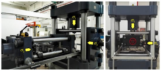
Figure 2.
True triaxial electro-hydraulic servo test system.
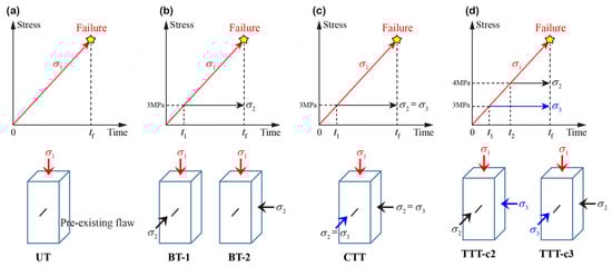
Figure 3.
Different test schemes of rock: (a) uniaxial test (UT); (b) biaxial test (BT), divided into two types: BT-1 and BT-2; (c) conventional triaxial test (CTT); (d) true triaxial test (TTT), divided into two types: TTT-c2 and TTT-c3.

Table 1.
Test schemes.
3. Stress–Strain Responses of Rocks
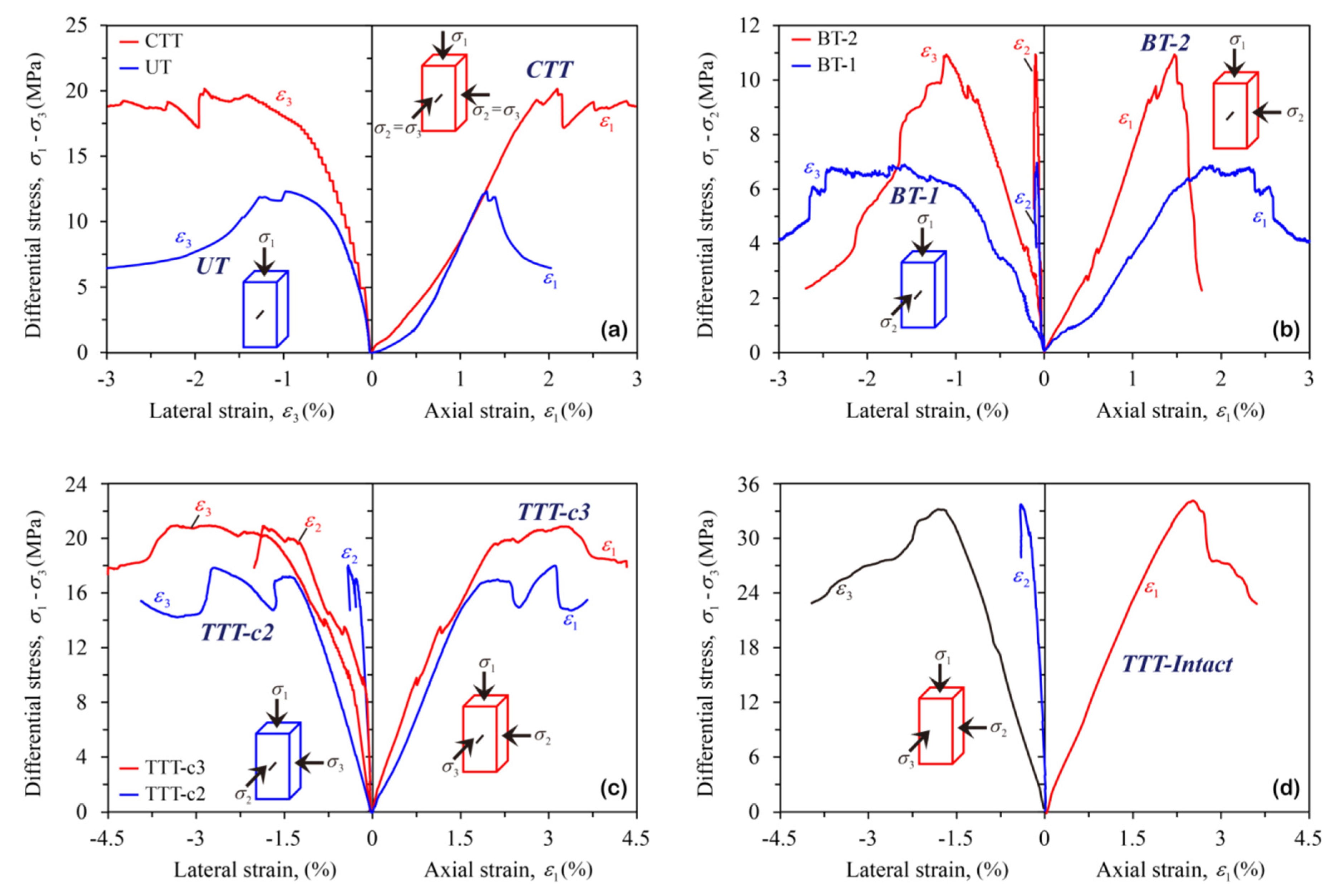
Figure 4 shows the variation in the typical stress–strain curves of the rock specimens under different test schemes. There is a certain similarity in the appearance of the rock deformation curve under both uniaxial and conventional triaxial stress conditions (Figure 4a), which is mainly due to the equal surrounding pressure ( and ) on the rocks. Due to the confining pressure > , the corresponding lateral deformation of true triaxial intact rock has obvious anisotropic characteristics, and the lateral deformation in direction is obviously limited (Figure 4d). The deformation and strength patterns of the rocks under the remaining two groups of stress conditions have similarities. The peak strength of the rocks when the prefabricated fracture is parallel to (BT-1 and TTT-c2) is lower than that of the same group where the prefabricated fracture direction is perpendicular to (BT-2 and TTT-c3). In the corresponding elastic stage, it can be found that the elastic modulus also has a similar law, that is, the tests of BT-1 and TTT-c2 are lower than those of BT-2 and TTT-c3, respectively. The difference is that the elastic modulus of BT-2 is much higher than that of BT-1 due to the large difference between and (3 MPa) and the superposition of prefabricated cracks. The elastic moduli of TTT-c2 and TTT-c3 are close. The reason for this is that the difference between and is small (1 MPa). Therefore, despite the superposition of prefabricated cracks, the elastic response has little difference, and the elastic modulus of TTT-c3 is only slightly higher than that of TTT-c2.
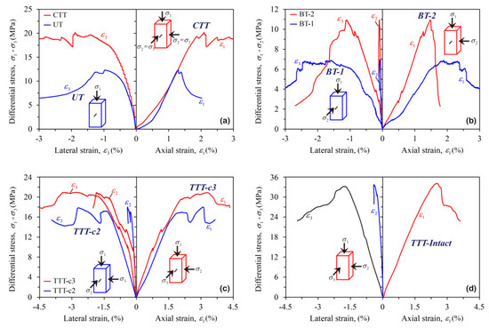
Figure 4.
Comparison of typical stress–strain curves of the rock under different test schemes: (a) UT vs. CTT; (b) BT-1 vs. BT-2; (c) TTT-c2 vs. TTT-c3; (d) TTT-Intact.
In addition, by analyzing the lateral expansion deformation of these two groups of rocks, it is found that these two groups of rock with lateral expansion deformation show obvious anisotropic characteristics (|| > ||). This is because the rock confining pressure is > , which leads to the suppression of deformation in the direction of the intermediate principal stress (); the lateral expansion and deformation are mainly along the direction. However, due to the existence of prefabricated cracks, the characteristics of the lateral deformation are slightly different. Taking the true triaxial tests of TTT-c2 and TTT-c3 as examples, the difference in lateral strain (|| − ||) under TTT-c2 condition is more significant than that under TTT-c3 condition. The main reason is that under the condition of TTT-c2, the prefabricated cracks are parallel to the direction, which intensifies the expansion in the direction of the minimum principal stress during the rock loading process, resulting in a larger deformation in the direction (), so the difference between the lateral strains (|| − ||) is higher. However, under the condition of TTT-c3, the prefabricated cracks are parallel to the direction. This weakens the inhibitory effect of the intermediate principal stress on the lateral expansion deformation to a certain extent, resulting in an increase in the direction deformation (), and the difference between the lateral strains (|| − ||) decreases.
4. Internal Fracture Characteristics of the Rock
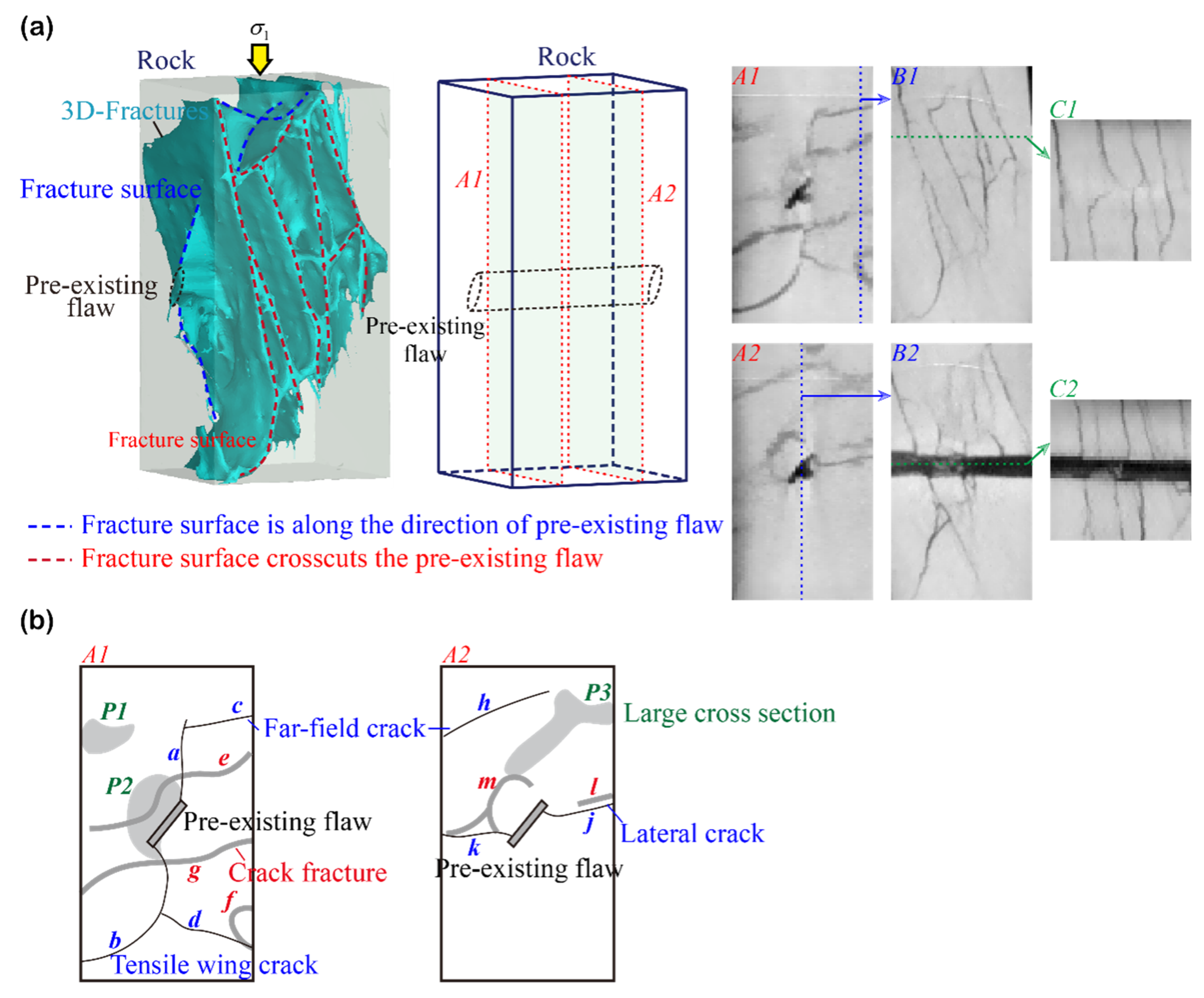
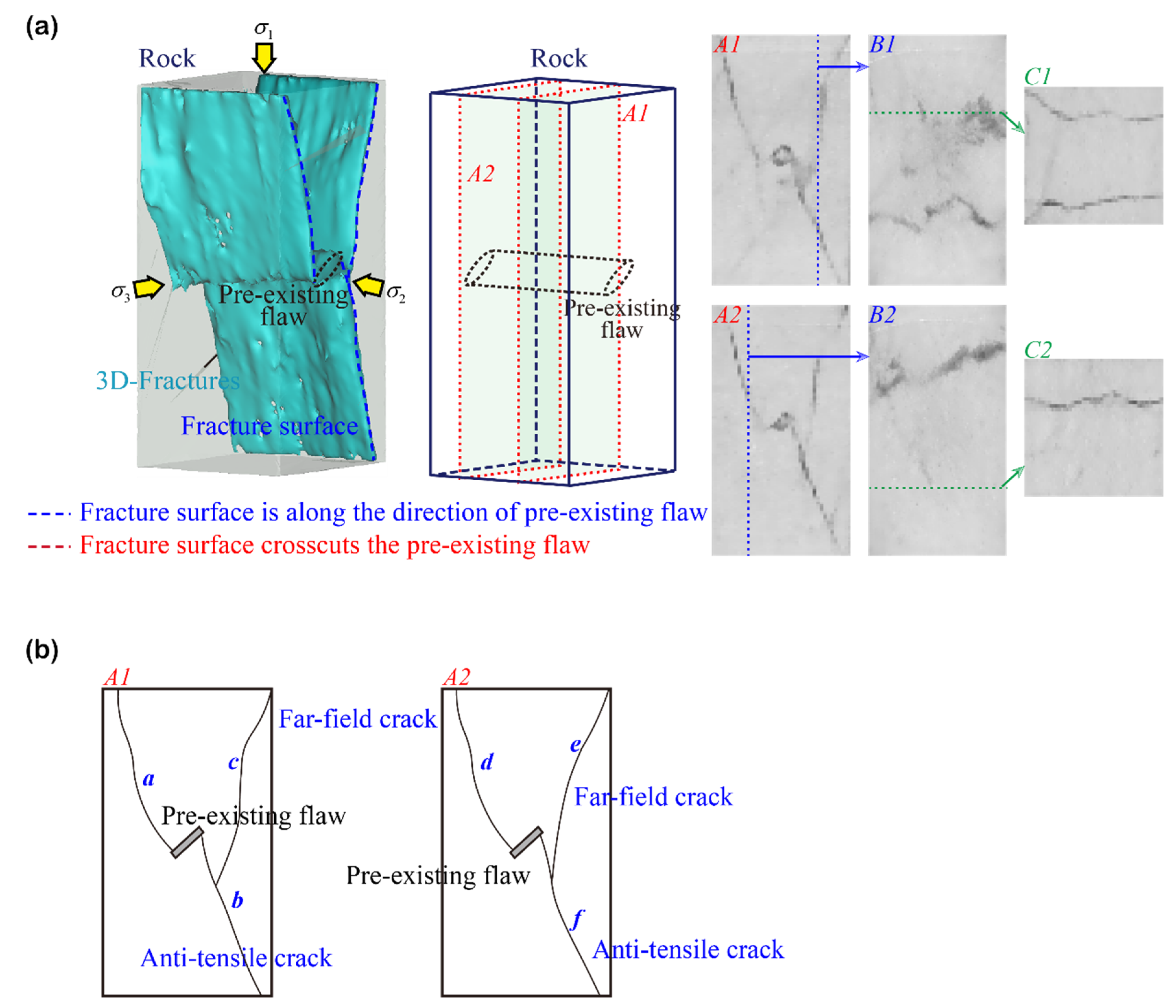
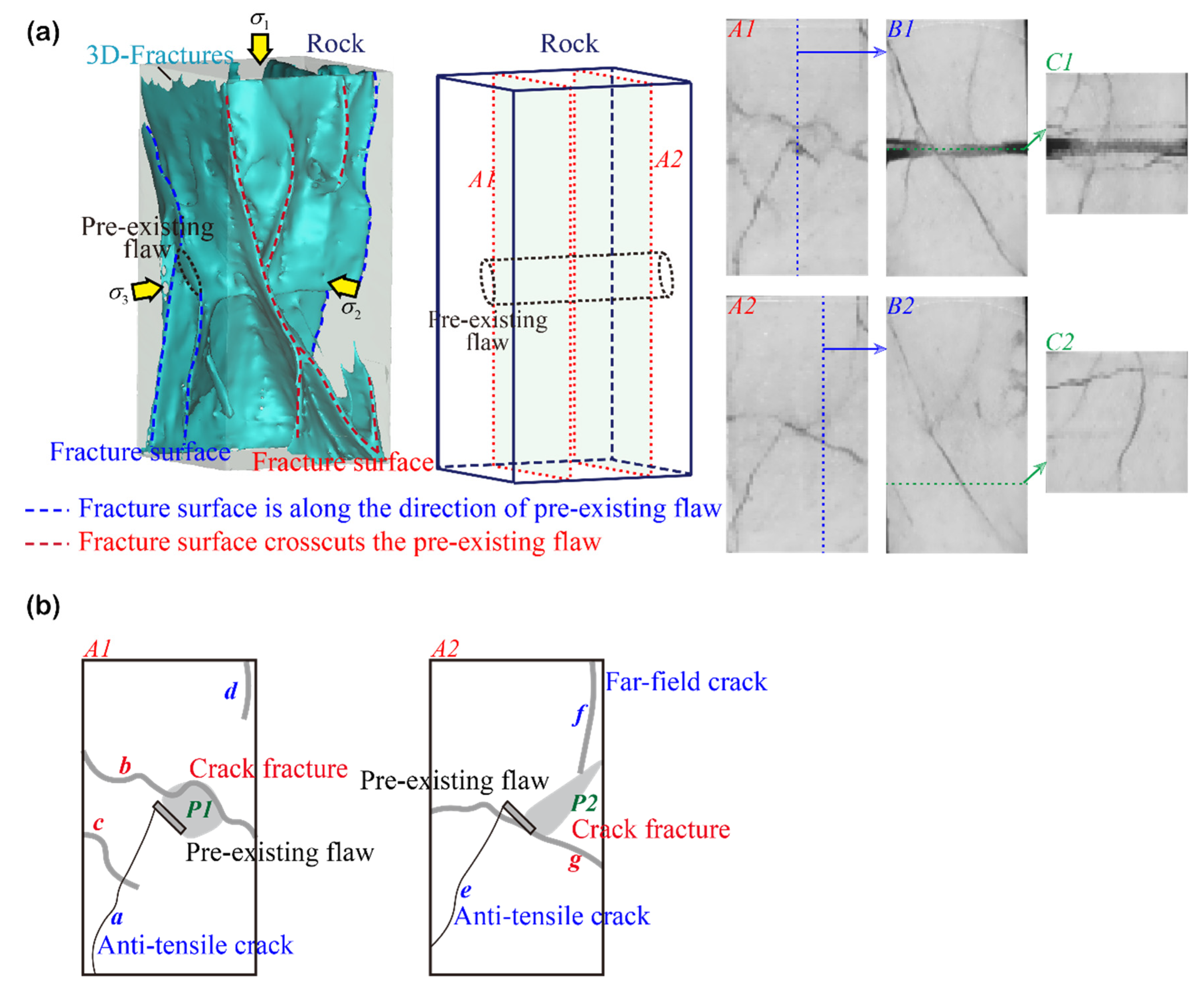
To reveal variations in the internal fracture structure produced in rocks containing prefabricated fractures subjected to different stress conditions, CT scanning tests were conducted on the post-rupture specimens. In CT technology, the detector obtains the corresponding projection data after the X-ray passes through the object to be measured and reconstructs the 3D image of the object through mathematical inversion calculations [42]. In this study, the spatial three-dimensional CT characteristics of the internal crack morphology of the rock specimens under different conditions were obtained from the CT images, as shown in Figure 5 (similar below). The light blue color in the figure represents the three-dimensional fractures inside the rock. The fracture surface is indicated by the blue dashed lines (representing the initiation cracks roughly along the direction of the prefabricated fractures) and red dashed lines (representing the direction of the initiation fractures crosscutting the prefabricated fractures). In addition, the CT images of different sections along different directions are shown in the figure. The thin, line-shaped cracks indicate that the CT section is perpendicular to or intersecting the crack surface, while the larger area of fuzzy cracks indicates that the CT section is roughly along the crack surface, which is expressed as a crack fracture.

Figure 5.
(a) Distribution of internal fissures in rocks with prefabricated fissures under UT; (b) Various crack types from single fissure identified.
Figure 5a shows the three-dimensional reconstructed images from CT scanning of rocks with prefabricated cracks under UT and the crack distribution on different sections. Combining three-dimensional fracture reconstruction features and different CT slice images, it can be seen that there is no confining pressure constraint under uniaxial conditions, or it can be considered that the confining pressure = = 0 (this article stipulates that and are parallel and perpendicular to the prefabricated fracture penetration direction, respectively, similar to the CTT condition below). A large number of longitudinal and transverse fractures occur in the interior of the rock along all directions (lateral and ), and there is a wide variety of fractures. Similar to the research of Yang et al. [43], this article simplifies the initiation cracks on the two sections of A1 and A2 (the two sections roughly divide the prefabricated cracks into three equal parts), as shown in Figure 5b.
Two tension wing cracks (a and b) along the direction are produced near the tip of the prefabricated fracture in the A1 section. The two cracks intersect with two other cracks (e and g) along the direction (in the form of the crack fracture in the A1 section), respectively, and form a larger cross-section P2, which truncates the prefabricated fracture, as can also be seen in the B2 and C2 sections. There are also many intersecting far-field cracks in the A1 section. For example, the cracks c and d along the direction intersect with the cracks a and b, respectively, and the crack f intersects with the crack d along the direction. Two relatively rare lateral cracks (k and j) are generated near the tip of the prefabricated crack on the A2 section. Both cracks are roughly perpendicular to the direction of the tension wing cracks (a and b), where crack k intersects crack m (which intersects with crack section P3) at multiple locations. Integrating sections B1 and C1, it can be found that more dense cracks are produced inside the rock under UT conditions, and intersections occur between multiple cracks. Comprehensive analysis of the above shows that due to the surrounding pressure = = 0, the internal crack expansion direction in the rock is more random, resulting in a more extensive and complex distribution of cracks.
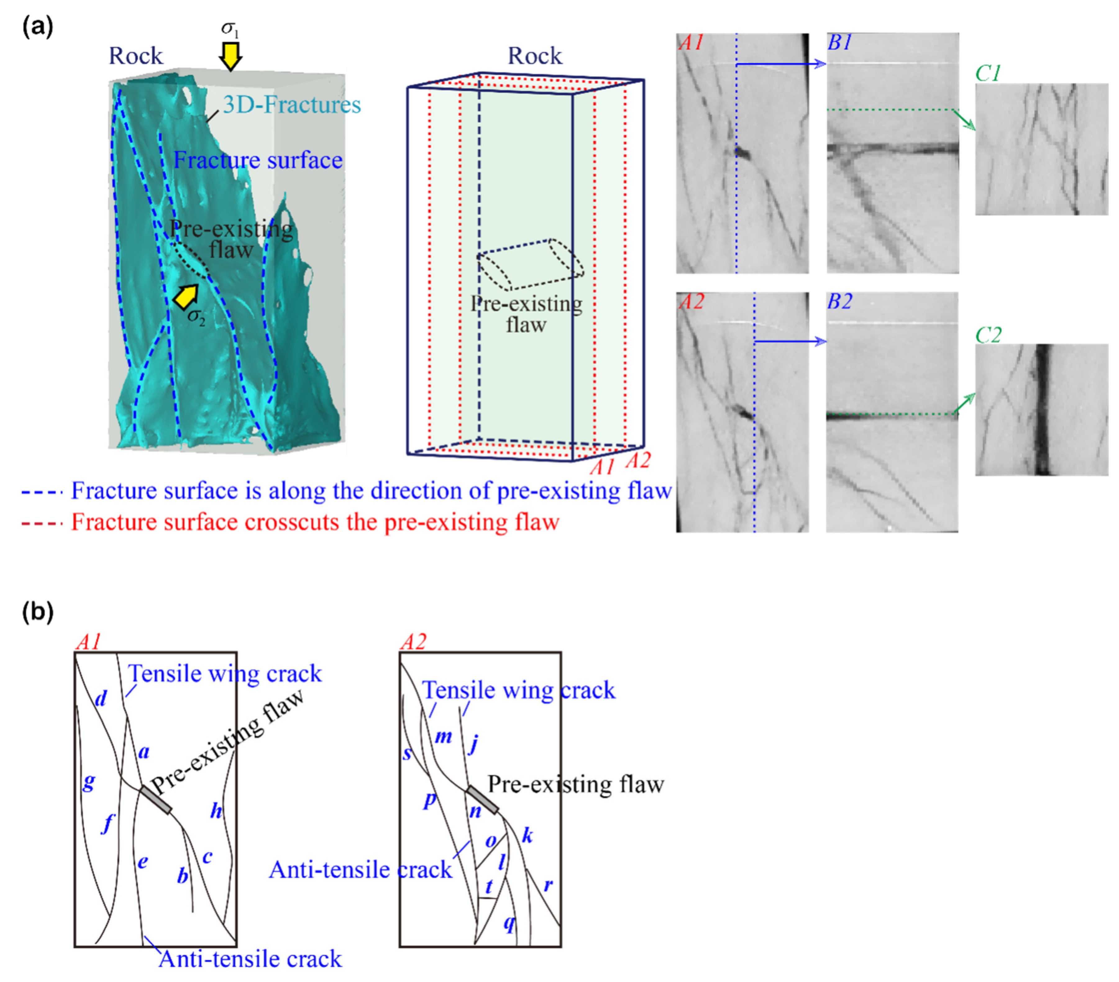
Figure 6a shows the three-dimensional reconstructed images from the CT scanning of rocks with prefabricated cracks under the condition of BT-1 and the crack distribution on different sections. Figure 6b shows a simplification of crack initiation and crack types on the two sections A1 and A2. Under the BT-1 condition, the initiation cracks basically propagate along the direction of because the rock surrounding pressure is along the prefabricated fracture penetration direction (Figure 6a); this is very different from the initiation crack spreading pattern under the UT condition. Many initiation cracks (sections A1 and A2) are generated near the prefabricated cracks, and multiple cracks intersect each other. Although the distribution of the cracks is more complicated, the crack propagation direction on the two sections is similar; that is, the cracks are along the direction (Figure 6b) and are linear cracks. Four tension wing cracks are produced in each of the two sections: a, b, c, d (section A1) and m, j, l, k (section A2). One anti-tension type crack is produced near each of the prefabricated crack tips: e (section A1) and n (section A2). In addition, multiple far-field cracks are produced in both sections and intersect with other types of cracks, such as f intersecting a, and q intersecting l, etc. Sections B1 and B2 are two tip sections along the prefabricated fissure, respectively, and it can be found that the prefabricated fissure remains intact, unlike in the UT condition. This indicates that the initiation crack expands along the direction (parallel to the prefabricated fracture penetration direction), which is also supported by sections C1 and C2. The comprehensive analysis above shows that due to the existence of the surrounding pressure , the expansion of the fractures in the rocks has a clear direction, which is roughly along the direction.

Figure 6.
(a) Distribution law of internal fissures in rock with prefabricated fissures under BT-1 condition; (b) Various crack types from a single fissure identified.
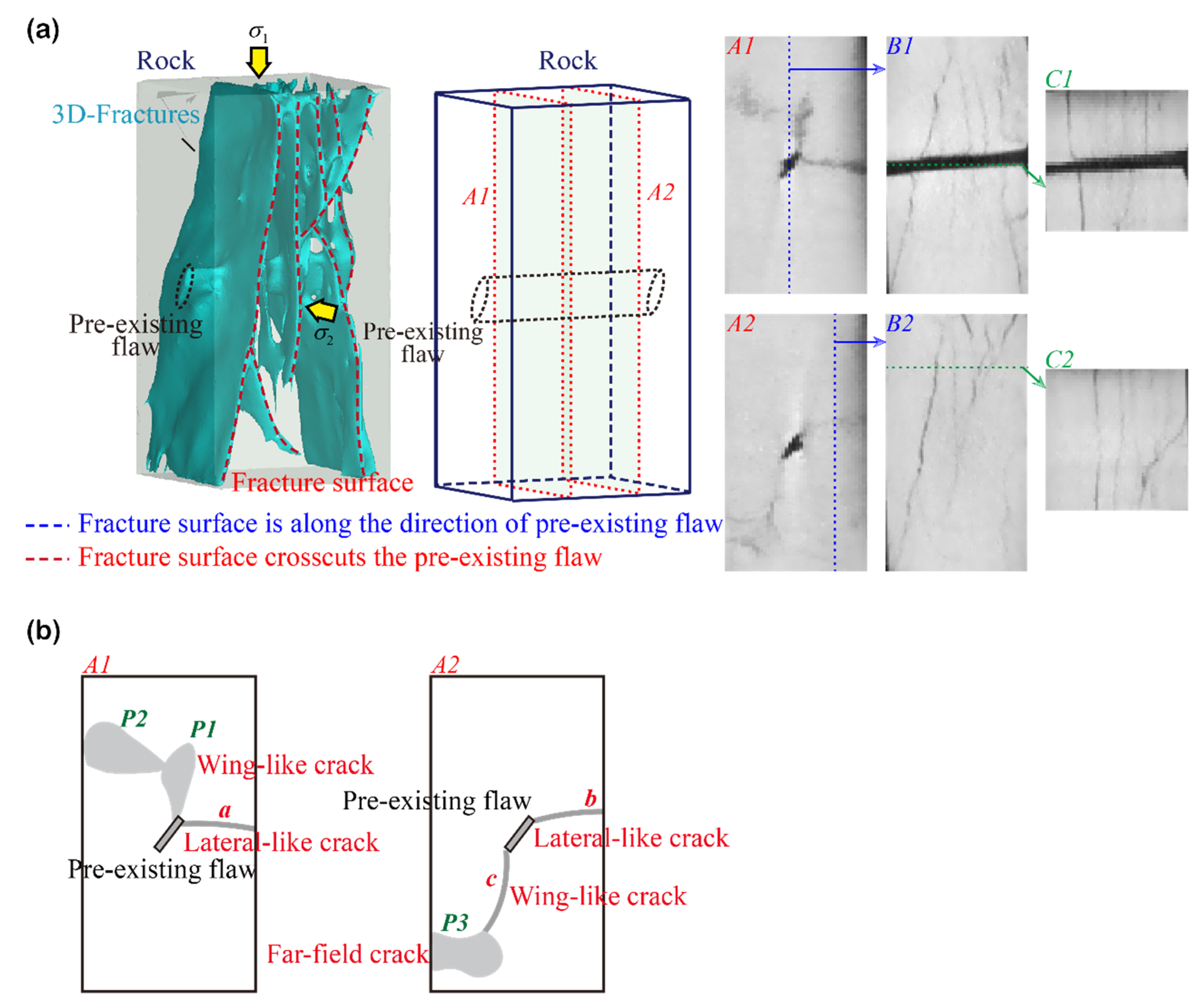
Compared with the BT-1 condition, the BT-2 condition only changes the direction of , but the distribution of the initiation cracks in the rock changes greatly. Most of the initiation cracks gradually follow the direction of the cross-cutting prefabricated cracks ( direction), as shown in Figure 7. Comparing the A1 and A2 sections shows that the initiation cracks are all fracture-like features. For example, a crack section P1 appears at the tip of the prefabricated crack in the A1 section, and it is similar to the traditional wing crack initiation location and expansion direction. However, the spatial geometries of these two are distinctly different (the former is cross-cutting, while the latter is parallel to the prefabricated crack penetration direction). In view of this, this article defines the crack section P1 as a wing-like crack, and similarly, the crack a is defined as a lateral-like crack. A wing-like crack c and a lateral-like crack b also appear near the prefabricated crack on section A2. Observing the B1 and C1 sections shows that all the initiation cracks are transverse to the prefabricated cracks. This indicates that compared with the BT-1 condition (BT-2 condition is regarded as having rotated 90° on the horizontal plane), the change in the direction has an important influence on the propagation direction of internal cracks in rocks; that is, the propagation direction changes immediately and is not affected (or is less influenced) by the prefabricated crack.
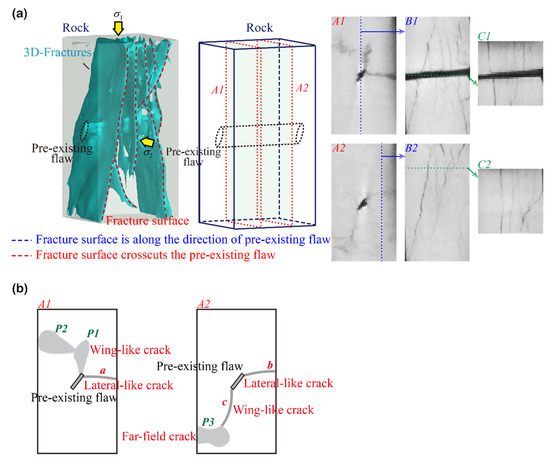
Figure 7.
(a) Distribution internal fissures in rocks with prefabricated fissures under the BT-2 condition; (b) Various crack types from a single fissure identified.
Figure 8a shows the three-dimensional reconstructed images from the CT scanning of rocks with prefabricated cracks under the condition of CTT and the crack distribution on different sections. Figure 8b shows a simplification of crack initiation and crack types on the two sections A1 and A2. Similar to the distribution of initiation cracks in the rock under the UT condition, linear cracks are generated along the directions of and (both equal in magnitude) under the CTT condition. It can be seen from the A1 and A2 sections that the anti-wing cracks a, e and f initiate from the vicinity of the prefabricated crack tip and gradually propagate along the direction; they also intersect with multiple far-field fracture cracks (such as b, c and h). Crack b is the initiation crack of a transversely cut prefabricated crack, which can also be seen in section B1. The C1 section shows that the initiation cracks are both parallel and transverse to the through direction of the prefabricated crack, indicating that the expansion direction of the internal fractures in the rock is more random and that the fracture distribution is more extensive and complex due to the surrounding pressure = . Comparing this with the UT conditions reveals that when = , there is no clear directionality of the internal fracture expansion due to no clear and unique , indicating that has a key effect on the expansion direction of internal fractures in rocks.

Figure 8.
(a) Distribution of internal fissures in rocks with prefabricated fissures under the CTT condition; (b) Various crack types from a single fissure identified.
Figure 9a shows the three-dimensional reconstruction images from the CT scanning of rocks with prefabricated cracks under the condition of TTT-c2 and the crack distribution on different sections. Figure 9b shows a simplification of crack initiation and crack types in the two sections, A1 and A2. The distribution of the initiation cracks in the rock is very simple. There are three main cracks: two anti-wing cracks and one far-field crack. The three main cracks are similar in the two sections, A1 and A2. It is laterally illustrated that the initiation cracks all expand along the direction, as can also be seen in the C1 and C2 sections. This indicates that has an important role in influencing crack extension due to the clear directionality of fracture extension within the rock under true triaxial conditions.
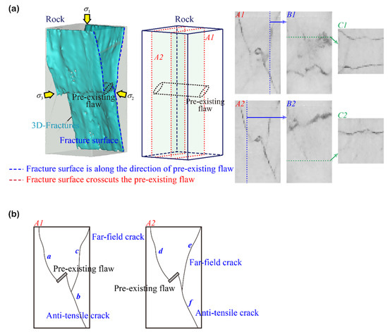
Figure 9.
(a) Distribution of internal fissures in rocks with prefabricated fissures under the TTT-c2 condition; (b) Various crack types from a single fissure identified.
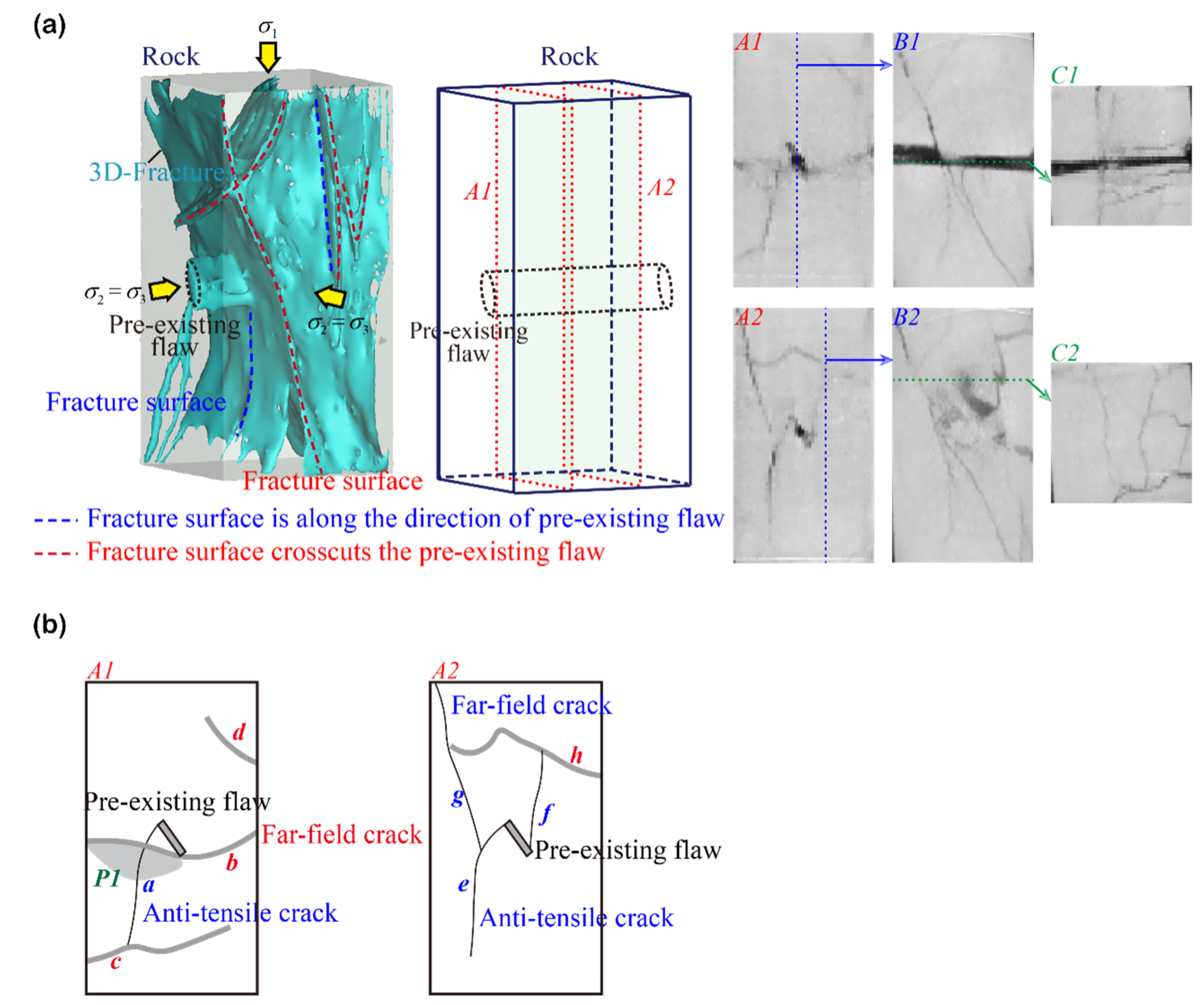
To further illustrate the effect of on the fracture extension pattern inside the rock, the was rotated by 90° in the horizontal direction, i.e., transverse to the prefabricated fracture penetration direction, under the TTT-c3 condition (Figure 10a). The A1 and A2 sections (Figure 10b) show that most of the emergent fractures are fracture-like features, such as larger fracture sections P1 and P2, where the fractures b and g cut off the prefabricated fractures, as can also be seen in the B1 and C1 sections. Comparison of the TTT-c2 conditions shows that the direction of crack extension within the rock is profoundly influenced by the change in the direction while it is less influenced by the prefabricated fractures. The six comprehensive groups of experimental studies can find that the extension of initiation cracks in rocks containing prefabricated fractures is strongly influenced by the direction, and the intermediate principal stress of the rock has a decisive role in the development of cracks in rocks.
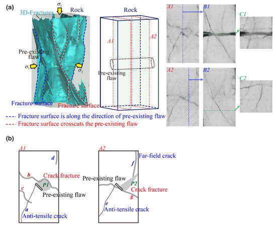
Figure 10.
(a) Distribution of internal fissures in rocks with prefabricated fissures under the TTT-c3 condition; (b) Various crack types from a single fissure identified.
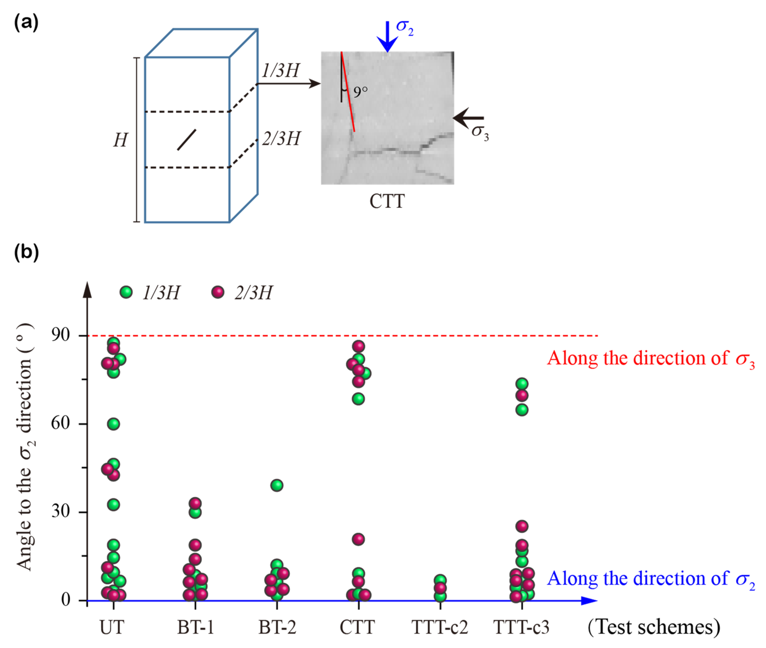
To further quantitatively describe the fracture extension direction under different stress conditions, two sections were selected along the rock height (H); these sections were at 1/3H and 2/3H (perpendicular to the direction), and they were selected to extract the angle between the initiation crack and the intermediate principal stress direction. The cracks on the section were simplified as multi-segment linear cracks, and the angle between each segment linear crack and the direction was extracted, with the value range of [0°, 90°]. When the angle is 0°, the crack is along the direction, while an angle of 90° corresponds to a crack along the direction (Figure 11a). Figure 11b demonstrates the distribution pattern of the angle between the initiating crack and the principal stress in the rock under different stress conditions. The dip angle distribution of cracks in rocks under the UT and CTT conditions is more extensive, but interestingly, the number of cracks parallel to the and directions is higher. However, actually at this time = , it can also be considered that the internal cracks of the rock are roughly parallel to the direction of . The distribution of the angle of the rocks under the other four stress conditions due to the clear direction is extremely concentrated around 0°, i.e., all the cracks are basically parallel to the direction. This indicates that the intermediate principal stress plays an important role in the propagation direction of the initiation cracks in the rock, and the development process of cracks in the rock tends to the direction of the intermediate principal stress. The results of this study serve as an important reference for the study of the evolution of rock mass fractures in underground engineering.
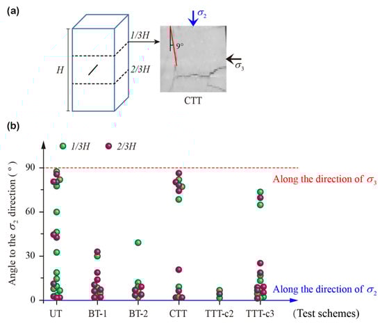
Figure 11.
(a) Simplified linear cracking model example under CTT conditions; (b) distribution of angle between initiation crack and intermediate principal stress of the rock under different stress conditions.
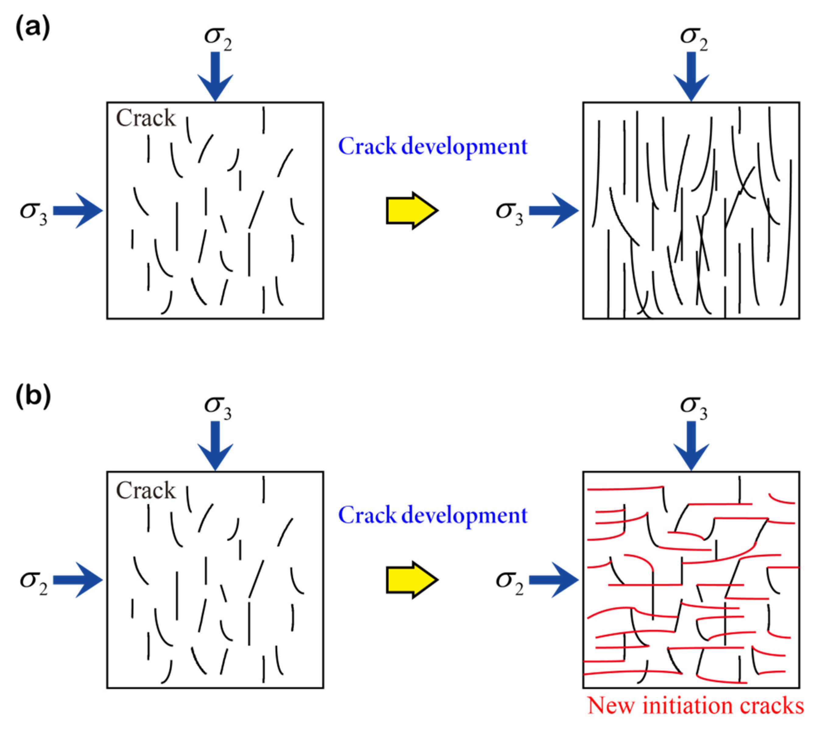
Furthermore, combined with the experimental results, Figure 12 shows the relationship between the intermediate principal stress and the crack propagation in the rock. When the initial direction of internal cracks in rock is consistent with the direction of intermediate principal stress, internal cracks in rock gradually develop and evolve along the original direction until the macroscopic failure of rock. Once the initial direction of cracks in rock is vertical or inconsistent with the direction of intermediate principal stress, the main fracture surface in rock will gradually change the propagation direction and develop along the direction to form a complex fracture network. This is consistent with the test results of BT-2 and TTT-c3 in the test. It shows that the intermediate principal stress has an important effect on the propagation law of internal fractures in the rock.

Figure 12.
The effect of intermediate principal stress on the propagation law of internal fractures in rock: (a) the initial direction of internal cracks is parallel to ; (b) the initial direction of internal cracks is perpendicular to .
5. Discussion
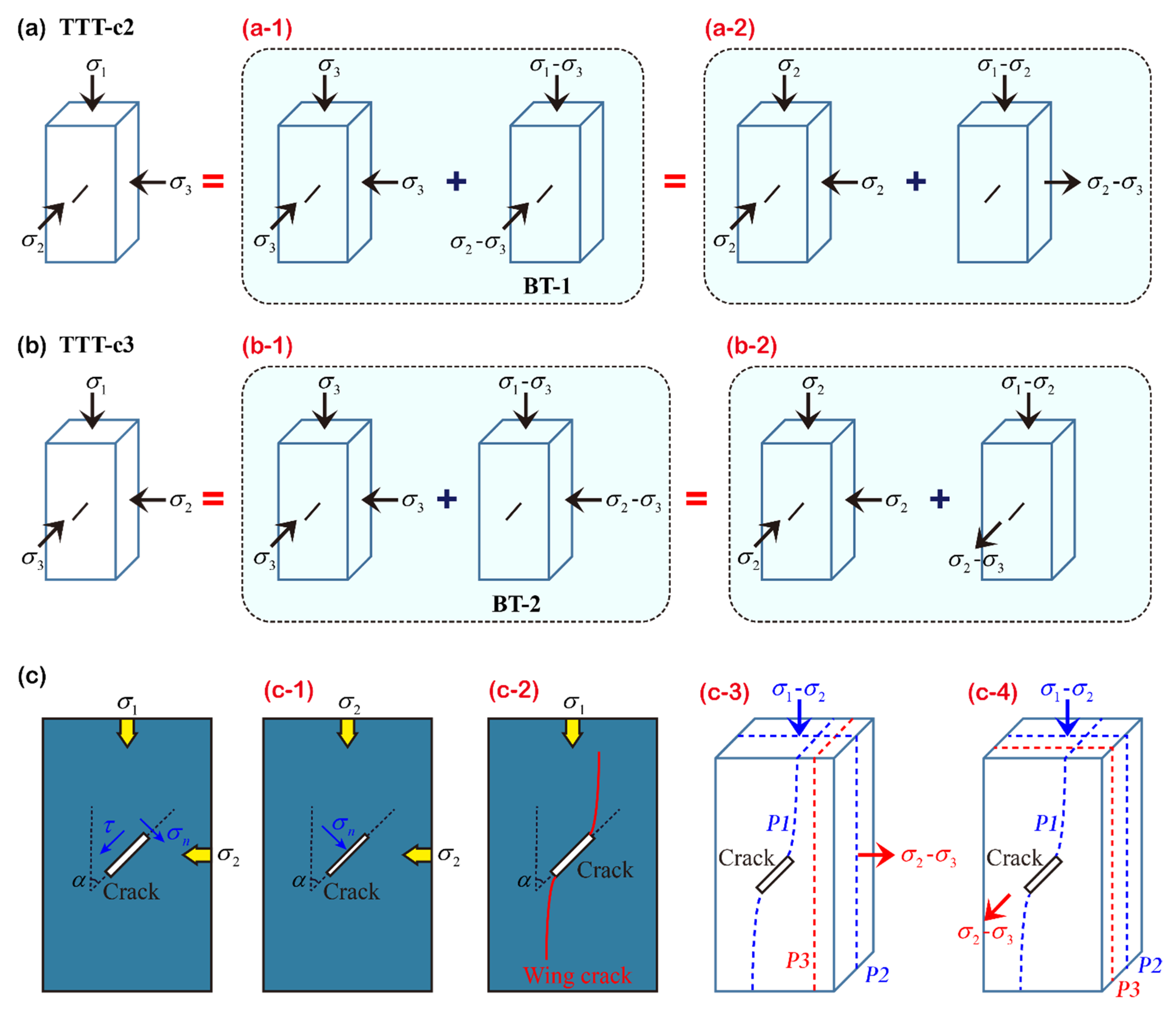
The above experimental study on rock with prefabricated cracks shows that intermediate principal stress plays an important role in the propagation of cracks in rock, and a simple theoretical explanation is given below. This manuscript focuses on the analysis of the stress state near the fracture under two conditions of true triaxial (TTT-c2 and TTT-c3, whose conditions can be considered as special true triaxial).
As shown in Figure 13, the triaxial stress state with prefabricated cracks is decomposed into the superposition of hydrostatic stress state and biaxial stress state. It should be noted that there are two superposition methods: Method (1), the hydrostatic pressure is , and the biaxial stress state is compression, corresponding to BT-1 (Figure 13(a-1)) and BT-2 (Figure 13(b-1)). Method (2) the hydrostatic pressure is , and the biaxial stress state is compression in one direction () and tension in the other direction (). The mechanical analysis will be carried out below.
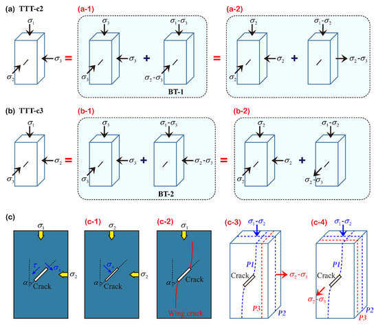
Figure 13.
Fracture mechanism of rock with prefabricated fractures: (a) the intermediate principal stress along the direction of prefabricated fracture; (b) the intermediate principal stress perpendicular to the direction of prefabricated fracture; (c) the law of fracture expansion direction.
For the crack section (Figure 13c), the normal stress and tangential stress on the fractured surface are respectively:
According to formula (1), when , the normal stress on the fracture surface is , and the tangential stress . The fissure is more likely to close at this time (Figure 13(c-1)). Therefore, for the hydrostatic pressure state ( or ) in the two superposition methods, crack propagation is less likely to occur. Therefore, the crack propagation is mainly affected by the bidirectional stress state. According to method (1), it can be seen that the fracture characteristics of rocks with prefabricated fractures under two true triaxial conditions (TTT-c2 and TTT-c3) are roughly similar to the biaxial compression conditions (corresponding to BT-1 and BT-2). The actual test results are basically consistent with this statement.
For method (2), the effects of compressive stress and tensile stress on the fracture development of rocks with prefabricated fractures are analyzed separately. Once the prefabricated cracks on the two-dimensional plane are under the action of uniaxial compressive stress, once the cracks start, according to the experimental results and theoretical analysis of many scholars [44], wing cracks will be generated along the compression direction (Figure 13(c-2)). For the three-dimensional space, in addition to generating the airfoil crack surface P1 (Figure 13(c-3,c-4)), the crack surface P2 can also be generated in the direction perpendicular to the prefabricated crack. This result was found in both uniaxial compression (UT) and conventional triaxial (CTT) experiments. From another point of view, since there is no clear direction, the crack propagation is relatively random. For tensile stress, the rock with lower tensile strength is more prone to failure, thus forming a fracture surface P3 in the tensile direction. After the superposition of compressive stress and tensile stress, the potential fracture surfaces P1 and P3 under the condition of TTT-c2 are roughly parallel, and it is easier to form the macroscopic main fracture surface along the prefabricated fracture direction (Figure 13(c-3)). Under the condition of TTT-c3, the potential fracture surfaces P2 and P3 are roughly parallel, and it is easier to form the macroscopic main fracture surface perpendicular to the direction of the prefabricated fractures. In both conditions, the macroscopic principal fracture direction is parallel to , again indicating that the fractures in the rock tend to the direction of the intermediate principal stress, while they are less affected by the prefabricated fractures.
6. Conclusions
In this study, a true triaxial electro-hydraulic servo test system was used to perform a series of true triaxial compression failure tests of rocks with prefabricated cracks. From the perspective of intermediate principal stress, its important role in the propagation and evolution of crack initiation in the rock is analyzed uniformly. The main conclusions are as follows:
- (1)
- The direction of the intermediate principal stress has a significant effect on the elasticity modulus and deformation characteristics of the prefabricated fractured rock. According to the variation law of typical stress–strain curve variation patterns of rocks under different test schemes, it is found that due to the influence of the intermediate principal stress, the lateral expansion deformation of the rock specimens under both biaxial and true triaxial conditions exhibited obvious anisotropic characteristics. The lateral strain in rocks when the prefabricated fissure penetration direction along is significantly higher than when the prefabricated fissure penetration direction is along , while the corresponding elastic modulus is relatively low.
- (2)
- The intermediate principal stress has an important influence on the law of fracture development in rock and leads to the clear direction of fracture development. According to the internal fracture spreading patterns in rocks containing prefabricated fractures under different test schemes, the internal crack expansion direction is more random, and the crack distribution is more extensive and complex due to the surrounding pressure = under uniaxial and conventional triaxial conditions. Under biaxial and true triaxial conditions, because the confining pressure > , the crack propagation direction is clearly along the direction. When is along the direction of the prefabricated crack (BT-1 and TTT-c2), the fracture distribution is along the direction of the prefabricated crack, which indicates that the initiation cracks propagate along the direction. By changing the direction of s2 in both conditions (i.e., the two conditions of BT-2 and TTT-c3), the internal fracture extension direction changes but is less affected by the prefabricated fractures. This conclusively shows that the expansion of initiation cracks in prefabricated rock is strongly affected by the direction.
- (3)
- The intermediate principal stress plays an important role in inducing the direction of crack initiation and propagation in rocks. The CT image section along the height direction of the specimen is quantitatively extracted, and the variation law of crack inclination is analyzed. The results show that the inclination angles of the internal cracks in the rock are widely distributed under uniaxial and conventional triaxial conditions. The crack inclination distributions under the four biaxial and true triaxial conditions are extremely concentrated, and they are all roughly parallel to the direction. This shows that the propagation and development process of internal cracks in rocks strongly tend to the direction of the intermediate principal stress.
- (4)
- The failure mechanism of rock with prefabricated cracks is analyzed based on theory. It is found that the intermediate principal stress (especially the direction) plays a very important role in inducing the direction of rock crack propagation. Combined with this manuscript, the mechanical behavior and fracture characteristics of fractured rocks under different triaxial conditions are analyzed from the perspective of intermediate principal stress, and the results are consistent with them. The important role of intermediate principal stress on the rock fracture is illustrated. This provides a new perspective for the study of rock fracture mechanics and provides an important basis for the analysis of surrounding rock fracture mechanism of underground engineering, the evaluation of surrounding rock stability and the guidance of engineering safety construction.
Author Contributions
Conceptualization, Z.L. and L.W.; data curation, Z.L.; formal analysis, Z.L.; funding acquisition, Z.L. and W.L.; investigation, Z.L. and W.L.; methodology, Z.L. and W.L.; resources, L.W.; software, Z.L.; writing—original draft, Z.L.; writing—review & editing, Z.L. and W.L. All authors have read and agreed to the published version of the manuscript.
Funding
This research was funded by Natural Science Foundation of Jiangsu Province, China (Grant No. BK20200628); China Postdoctoral Science Foundation funded project (Grant No. 2020M671649); and the Fundamental Research Funds for the Central Universities (Grant No. 2020QN42).
Data Availability Statement
The data used to support the findings of this study are included within the article.
Acknowledgments
The authors would like to acknowledge the editor for their valuable comments on the improvement of this paper.
Conflicts of Interest
The authors declare that there is no conflict of interest regarding the publication of this paper.
References
- Basu, D.; Misra, A.; Puppala, A.J. Sustainability and geotechnical engineering: Perspectives and review. Can. Geotech. J. 2015, 52, 96–113. [Google Scholar] [CrossRef]
- Janeček, I.; Mishra, D.A. Deformational Response of Rocks to Uniaxial, Biaxial, and Triaxial Loading or Unloading Regimes. Procedia. Eng. 2017, 191, 332–341. [Google Scholar] [CrossRef]
- Wang, D.; Zeng, F.; Wei, J.; Zhang, H.; Wu, Y.; Wei, Q. Quantitative analysis of fracture dynamic evolution in coal subjected to uniaxial and triaxial compression loads based on industrial CT and fractal theory. J. Pet. Sci. Eng. 2021, 196, 108051. [Google Scholar] [CrossRef]
- Oda, M.; Hatsuyama, Y.; Ohnishi, Y. Numerical experiments on permeability tensor and its application to jointed granite at Stripa Mine, Sweden. J. Geophys. Res. Solid Earth 1987, 92, 2156–2202. [Google Scholar] [CrossRef]
- Zhang, Q.; Ma, D.; Liu, J.; Zhang, K.; Fan, Z. Numerical Studies on the Failure Process of Heterogeneous Rock Material with Preexisting Fracture under Uniaxial Compression. Adv. Civ. Eng. 2018, 2018, 9203549. [Google Scholar] [CrossRef]
- Bai, Q.; Tibbo, M.; Nasseri, M.H.B.; Young, R.P. True Triaxial Experimental Investigation of Rock Response Around the Mine-By Tunnel Under an In Situ 3D Stress Path. Rock Mech. Rock Eng. 2019, 52, 3971–3986. [Google Scholar] [CrossRef]
- Zhou, Z.; Cao, P.; Ye, Z. Crack propagation mechanism of compression-shear rock under static-dynamic loading and seepage water pressure. J. Cent. South Univ. 2014, 21, 1565–1570. [Google Scholar] [CrossRef]
- Zhao, X.G.; Wang, J.; Cai, M.; Cheng, C.; Ma, L.K.; Su, R.; Zhao, F.; Li, D.J. Influence of Unloading Rate on the Strainburst Characteristics of Beishan Granite Under True-Triaxial Unloading Conditions. Rock. Mech. Rock. Eng. 2014, 47, 467–483. [Google Scholar] [CrossRef]
- Read, R.S. 20 years of excavation response studies at AECL’s Underground Research Laboratory. Int. J. Rock Mech. Min. 2004, 41, 1251–1275. [Google Scholar] [CrossRef]
- Nguyen, T.L.; Hall, S.A.; Vacher, P.; Viggiani, G. Fracture mechanisms in soft rock: Identification and quantification of evolving displacement discontinuities by extended digital image correlation. Tectonophysics 2011, 503, 117–128. [Google Scholar] [CrossRef]
- Zhang, J.; Zhou, X. AE event rate characteristics of flawed granite: From damage stress to ultimate failure. Geophys. J. Int. 2020, 222, 795–814. [Google Scholar] [CrossRef]
- Liang, D.; Zhang, N.; Liu, H.; Fukuda, D.; Rong, H. Hybrid finite-discrete element simulator based on GPGPU—Parallelized computation for modelling crack initiation and coalescence in sandy mudstone with prefabricated cross-flaws under uniaxial compression. Eng. Fract. Mech. 2021, 247, 107658. [Google Scholar] [CrossRef]
- Liang, Z.Z.; Xing, H.; Wang, S.Y.; Williams, D.J.; Tang, C.A. A three-dimensional numerical investigation of the fracture of rock specimens containing a pre-existing surface flaw. Comput. Geotech. 2012, 45, 19–33. [Google Scholar] [CrossRef]
- Pakzad, R.; Wang, S.; Sloan, S. Numerical study of the failure response and fracture propagation for rock specimens with preexisting flaws under compression. Int. J. Geomech. 2018, 18, 04018070. [Google Scholar] [CrossRef]
- Zhou, X.; Zhang, J.; Qian, Q.; Niu, Y. Experimental investigation of progressive cracking processes in granite under uniaxial loading using digital imaging and AE techniques. J. Struct. Geol. 2019, 126, 129–145. [Google Scholar] [CrossRef]
- Haeri, H.; Shahriar, K.; Marji, M.F.; Moarefvand, P. Experimental and numerical study of crack propagation and coalescence in pre-cracked rock-like disks. Int. J. Rock Mech. Min. 2014, 67, 20–28. [Google Scholar] [CrossRef]
- Bastola, S.; Cai, M. Investigation of mechanical properties and crack propagation in pre-cracked marbles using lattice-spring-based synthetic rock mass (LS-SRM) modeling approach. Comput. Geotech. 2019, 110, 28–43. [Google Scholar] [CrossRef]
- Zhenghe, L.; Xiaokai, R.; Xiao, L.; Haojie, L.; Lusheng, Y.; Jianfeng, Y. Effects of Confining Stresses, Pre-crack Inclination Angles and Injection Rates: Observations from Large-Scale True Triaxial and Hydraulic Fracturing Tests in Laboratory. Rock Mech. Rock Eng. 2019, 53, 1991–2000. [Google Scholar]
- Sahouryeh, E.; Dyskin, A.V.; Germanovich, L.N. Crack growth under biaxial compression. Eng. Fract. Mech. 2002, 69, 2187–2198. [Google Scholar] [CrossRef]
- Bi, J.; Zhou, X.P.; Qian, Q.H. The 3D Numerical Simulation for the Propagation Process of Multiple Pre-existing Flaws in Rock-Like Materials Subjected to Biaxial Compressive Loads. Rock. Mech. Rock. Eng. 2016, 49, 1611–1627. [Google Scholar] [CrossRef]
- Manouchehrian, A.; Marji, M.F. Numerical analysis of confinement effect on crack propagation mechanism from a flaw in a pre-cracked rock under compression. Acta Mech. Sin. 2012, 28, 1389–1397. [Google Scholar] [CrossRef]
- Wang, M.; Cao, P. Experimental Study of Crack Growth in Rock-Like Materials Containing Multiple Parallel Pre-existing Flaws Under Biaxial Compression. Geotech. Geol. Eng. 2017, 35, 1023–1034. [Google Scholar] [CrossRef]
- Liu, X.; Liu, Q.; Liu, B.; Zhu, Y.; Zhang, P. Failure behavior for rocklike material with cross crack under biaxial compression. J. Mater. Civ. Eng. 2019, 31, 06018025. [Google Scholar] [CrossRef]
- Wu, J.; Feng, M.; Yu, B.; Han, G. The length of pre-existing fissures effects on the mechanical properties of cracked red sandstone and strength design in engineering. Ultrasonics 2018, 82, 188–199. [Google Scholar] [CrossRef] [PubMed]
- Wang, H.; Dyskin, A.; Pasternak, E.; Dight, P.; Sarmadivaleh, M. Experimental and Numerical Study into 3D Crack Growth from a Spherical Pore in Biaxial Compression. Rock Mech. Rock Eng. 2019, 53, 77–102. [Google Scholar] [CrossRef]
- Eberhardt, E. Numerical modelling of three-dimension stress rotation ahead of an advancing tunnel face. Int. J. Rock Mech. Min. 2001, 38, 499–518. [Google Scholar] [CrossRef]
- Huang, Y.; Yang, S.; Tian, W. Crack coalescence behavior of sandstone specimen containing two pre-existing flaws under different confining pressures. Theor. Appl. Fract. Mech. 2019, 99, 118–130. [Google Scholar] [CrossRef]
- Lisjak, A.; Grasselli, G. A review of discrete modeling techniques for fracturing processes in discontinuous rock masses. J. Rock Mech. Geotech. 2014, 6, 301–314. [Google Scholar] [CrossRef] [Green Version]
- Gunarathna, G.; Gonçalves Da Silva, B. Effect of the Triaxial State of Stress in the Hydraulic Fracturing Processes of Granite: Part 1—Visual Observations and Interpretation. Rock Mech. Rock Eng. 2021, 54, 2903–2923. [Google Scholar] [CrossRef]
- Yang, S.Q.; Huang, Y.H.; Ranjith, P.G. Failure mechanical and acoustic behavior of brine saturated-sandstone containing two pre-existing flaws under different confining pressures. Eng. Fract. Mech. 2018, 193, 108–121. [Google Scholar] [CrossRef]
- Xu, H.; Qin, Y.; Wang, G.; Fan, C.; Wu, M.; Wang, R. Discrete element study on mesomechanical behavior of crack propagation in coal samples with two prefabricated fissures under biaxial compression. Powder Technol. 2020, 375, 42–59. [Google Scholar] [CrossRef]
- Huang, D.; Gu, D.; Yang, C.; Huang, R.; Fu, G. Investigation on mechanical behaviors of sandstone with two preexisting flaws under triaxial compression. Rock Mech. Rock Eng. 2016, 49, 375–399. [Google Scholar] [CrossRef]
- Lu, Y.; Li, W.; Wang, L.; Li, Z.; Zhang, K. Damage Evolution and Failure Behavior of Sandstone under True Triaxial Compression. Geotech. Test. J. 2019, 42, 610–637. [Google Scholar] [CrossRef]
- Lu, J.; Yin, G.; Zhang, D.; Gao, H.; Li, C.; Li, M. True triaxial strength and failure characteristics of cubic coal and sandstone under different loading paths. Int. J. Rock Mech. Min. 2020, 135, 104439. [Google Scholar] [CrossRef]
- Feng, X.-T.; Xu, H.; Yang, C.; Zhang, X.; Gao, Y. Influence of Loading and Unloading Stress Paths on the Deformation and Failure Features of Jinping Marble Under True Triaxial Compression. Rock Mech. Rock Eng. 2020, 53, 3287–3301. [Google Scholar] [CrossRef]
- Jiang, B.; Gu, S.; Wang, L.; Zhang, G.; Li, W. Strainburst process of marble in tunnel-excavation-induced stress path considering intermediate principal stress. J. Cent. South. Univ. 2019, 26, 984–999. [Google Scholar] [CrossRef]
- Kwasniewski, M. Recent advances in studies of the strength of rocks under true triaxial compression conditions. Arch. Min. Sci. 2013, 58, 1177–1200. [Google Scholar]
- Ma, X.; Saar, M.O.; Fan, L.-S. Coulomb criterion-bounding crustal stress limit and intact rock failure: Perspectives. Powder Technol. 2020, 374, 106–110. [Google Scholar] [CrossRef]
- Su, G.; Jiang, J.; Feng, X.; Jiang, Q.; Chen, Z.; Mo, J. Influence of loading rate on strainburst: An experimental study. Bull. Eng. Geol. Environ. 2019, 78, 3559–3573. [Google Scholar] [CrossRef]
- Zhang, Y.; Feng, X.T.; Yang, C.X.; Han, Q.; Wang, Z.F.; Kong, R. Evaluation Method of Rock Brittleness under True Triaxial Stress States Based on Pre-peak Deformation Characteristic and Post-peak Energy Evolution. Rock Mech. Rock Eng. 2021, 54, 1277–1291. [Google Scholar] [CrossRef]
- Li, Z.; Wang, L.; Lu, Y.; Li, W.; Wang, K.; Fan, H. Experimental investigation on True Triaxial Deformation and Progressive Damage Behaviour of Sandstone. Sci. Rep. 2019, 9, 442–455. [Google Scholar] [CrossRef] [PubMed] [Green Version]
- Cao, W.; Yildirim, B.; Durucan, S.; Wolf, K.-H.; Cai, W.; Agrawal, H.; Korre, A. Fracture behaviour and seismic response of naturally fractured coal subjected to true triaxial stresses and hydraulic fracturing. Fuel 2021, 288, 119618. [Google Scholar] [CrossRef]
- Yang, S.Q.; Jing, H.W. Strength failure and crack coalescence behavior of brittle sandstone samples containing a single fissure under uniaxial compression. Int. J. Fract. 2011, 168, 227–250. [Google Scholar] [CrossRef]
- Wang, S.; Zhang, J.; Zhao, L.; Zhang, W. Phase field modeling of anisotropic tension failure of rock-like materials. Front. Phys. 2021, 9, 720. [Google Scholar] [CrossRef]
Publisher’s Note: MDPI stays neutral with regard to jurisdictional claims in published maps and institutional affiliations. |
© 2022 by the authors. Licensee MDPI, Basel, Switzerland. This article is an open access article distributed under the terms and conditions of the Creative Commons Attribution (CC BY) license (https://creativecommons.org/licenses/by/4.0/).