Article

A CaH2-Assisted Reduction Method to Prepare Nanoscale Zero-Valent Iron (nZVI) from Fe2O3 for Water Remediation Application

1
Renewable Energy Research Centre, National Institute of Advanced Industrial Science and Technology, 2-2-9 Machiikedai, Koriyama 963-0298, Japan
2
Department of Chemical Science and Engineering, National Institute of Technology, Tokyo College, 1220-2 Kunugida, Hachioji 193-0997, Japan
*
Author to whom correspondence should be addressed.
Minerals 2023, 13(11), 1385; https://doi.org/10.3390/min13111385
Submission received: 29 September 2023 / Revised: 24 October 2023 / Accepted: 25 October 2023 / Published: 29 October 2023
(This article belongs to the Section Mineral Processing and Extractive Metallurgy)

Abstract

:
In recent decades, nanoscale zero-valent iron (nZVI) has been extensively studied for application in environmental remediation because it is an eco-friendly, inexpensive nanomaterial with high reactivity. The chemical reduction of iron ions using NaBH4 in a liquid solution is the most frequently used method to obtain nZVI, but its drawbacks are the use of expensive and toxic NaBH4 and the secondary pollution caused by the B(OH)3 by-product. In this study, in order to obtain nZVI in a cleaner manner, we used a reduction method for Fe2O3 using CaH2, which is non-toxic and generates no pollutants. The results of X-ray diffraction, nitrogen adsorption, and scanning electron microscopy for the obtained samples indicated the formation of zero-valent iron nanopowder (22.5 m2/g) that was obtained via reduction at 220 °C for 5 h. The obtained nZVI was finally tested in the catalytic hydrogenation of p-nitrophenol as a model reaction of water remediation, verifying its good catalytic performance.

1. Introduction

Iron manufacturing is one of the most energy-intensive industries [1,2]. In addition, the use of coal as the primary fuel for iron production causes the release of significant levels of carbon dioxide emissions. A promising alternative process to reduce these emissions is the direct reduction in iron ore using green hydrogen that is produced via water electrolysis when operated using renewable energy [3,4,5,6,7,8]. This can not only contribute to the reduction in CO2 emissions but can also weaken the dependence on fossil fuels for iron and steel manufacturing. According to previous reports on the fundamental studies of the H2 reduction of Fe2O3, which is the main component of iron ore, Fe2O3 is gradually deoxidized by H2, following the order of Fe2O3, Fe3O4, FeO, and metallic Fe [9,10,11,12,13,14,15,16,17]. A high temperature (e.g., >500 °C) is commonly required to complete the reduction with H2. The existence of H2O, which is also a by-product generated during reduction, causes a significant increase in the reduction temperature [18,19]. Thus, controlling the H2O concentration in the hydrogen-based reduction in Fe2O3, or iron ore, is important to achieve a mild low-temperature reduction.
Calcium hydride is known to be a strong reducing agent, including hydride ions (H) with a low reduction potential of −2.23 V vs. a standard hydrogen electrode, which allows for the reduction from Fe3+ to Fe0 at 180–300 °C [20,21,22,23]. In addition, CaH2 is commonly used as an approachable drying agent in organic synthesis, and it has been reported that the drying capacity also assists in decreasing the Fe3O4-to-α-Fe reduction temperature from 400 °C to 300 °C [24]. In this work, we attempted to obtain nanoscale iron powder by reducing commercial Fe2O3 with a CaH2-reducing agent at a low reduction temperature of 220 °C. In addition, the same reduction was also conducted using molten NaOH-KOH that was used to in situ anneal the reduced iron to improve its crystallinity and increase the ease of handling. Some iron nanopowders, especially those of <100 nm, are also called nanoscale zero-valent iron (nZVI) [25,26,27,28,29,30,31]. In recent decades, nZVI has been extensively studied for applications in the remediation of soil [32,33] and water [34,35,36,37,38]. It is an environmentally friendly, inexpensive nanomaterial with high reactivity and efficiency for the removal of contaminants. The preparation of nZVI is categorized into physical and chemical methods [39,40,41,42]. For the physical method, iron nanoparticles are obtained via milling [43,44], and laser ablation [45]. Chemical methods, such as NaBH4 reduction [46,47,48,49,50] with the assistance of an ultrasound treatment [51], carbothermal reduction [52], chemical vapor condensation [53], hydrothermal carbonization [54], a polyol process [55,56], electrochemical approaches [57,58], and green synthesis [59,60,61], are paid more attention, mainly due to their good approachability without the need for large-scale special apparatus and facilities required for the physical method. Among the methods described above, the NaBH4 reduction method is the most frequently used because homogeneous nanoparticles are obtained with simple procedures and mild conditions. One of the disadvantages of the method is the use of the expensive and toxic reducing agent NaBH4 [39,41,42]. The solution method requires an excess of NaBH4 that is much higher than that required in stoichiometry. This excess implies that a large fraction of NaBH4 is wasted due to hydrolysis with water, and this high cost may deter scaled-up applications [62]. In addition, when iron ions are reduced to zero-valent iron with NaBH4, a by-product of B(OH)3 is produced at the same time, and this causes secondary pollution [39]. In this work, we used CaH2 as a reducing agent. It includes only calcium and hydrogen elements, and thus the by-products generated when it is used as a reducing agent are only nontoxic calcium species, such as CaO and Ca2+. Therefore, CaH2 could be an environmentally friendly reducing agent for the preparation of nZVI.
To evaluate the applicability of the obtained iron nanopowder to water remediation, the hydrogenation of p-nitrophenol to p-aminophenol with NaBH4 was chosen as a model reaction. In general, nZVI is more reactive than conventional microscale iron powder due to its high specific surface area with active sites for surface reaction. In other words, nZVI itself is unstable, and thus it is very important to obtain the stabilized nZVI, especially for the application aspect. Some techniques used to stabilize the nZVI have been reported [63]. The stability of nZVI can be improved via surface modification [64,65,66,67,68] and fixation on stable supports [69,70,71]. To evaluate the stability of the prepared samples in this study, catalytic reactions were also performed with previously water-soaked samples for 3 days, in addition to the as-prepared samples.

2. Materials and Methods

First, 3 different mixtures were prepared in mortar within an argon-filled glove box: (1) α-Fe2O3 (99.9%, Wako Pure Chem. Corp., Osaka, Japan) and CaH2 (94.0%, JUNSEI Chem. Co., Ltd., Tokyo, Japan), with a weight ratio of α-Fe2O3/CaH2 = 1/3; (2) α-Fe2O3, CaH2, and a molten salt source of NaOH (93.0%, Wako Pure Chem. Corp., Osaka, Japan) and KOH (85.0%, Wako Pure Chem. Corp., Osaka, Japan), with a weight ratio of α-Fe2O3/CaH2/NaOH/KOH = 3/9/7/11; (3) α-Fe2O3, and the same molten salt source [72]. Next, the separate mixed powders were loaded into stainless steel reactors and heated with argon at 220 °C for 5 h. Finally, the reduced mixtures were crushed using a mortar under atmospheric pressure and rinsed with a 0.1 M NH4Cl aqueous solution made of NH4Cl (99.5%, Wako Pure Chem. Corp.), followed by rinsing with distilled water and acetone to obtain the final product powders, denoted as Fe(C), Fe(CNK), and Fe(NK), obtained from mixtures (1), (2), and (3), respectively. The samples were kept in the glove box to prevent oxidation.
The crystal structure of the obtained samples was examined by X-ray diffraction (XRD, SmartLab, 3 kW, Rigaku, Tokyo, Japan) with CuKα radiation at 40 kV and 30 mA. The measurements ranged from 20° to 100° with a step interval of 0.01° and a scan speed of 10°/min. The porosity was investigated by N2 adsorption and desorption at −196 °C (BELLSORP mini-II, MicrotracBEL Corp., Osaka, Japan). The sample was pre-treated at 150 °C for 1 h under vacuum before the measurement. The morphology was observed by a scanning electron microscope (SEM, JSM-7800 F, JEOL, Ltd., Tokyo, Japan). The chemical states and composition of the prepared samples’ surface were determined using X-ray photoelectron spectroscopy (XPS) (PHI X-tool, ULVAC-PHI, Inc., Kanagawa, Japan) operated with AlKα radiation. The chemical shifts were calibrated by fixing the C1s peak of the surface carbonaceous contaminants at 284.8 eV. The analysis of the obtained signals was conducted by the installed software.
The catalytic hydrogenation of p-nitrophenol (4−NP) to p-aminophenol (4−AP) was conducted with Fe(C) and Fe(CNK). Both samples, with two different conditions of as-prepared and after being water-soaked for 3 days, were tested to evaluate the samples’ stability. The catalytic reactions were conducted in 20 mL glass bottles following the previously reported procedures [73,74]. In the catalytic tests, 1 mL of 4−NP solution (14 mM) was added to a bottle containing 10 mg of catalyst powder, 1 mL of NaBH4 solution (0.42 M), and 7 mL of distilled water as the solvent. To satisfy first-order reaction kinetics, the initial concentration of NaBH4 (0.047 M) was 30 times higher than that of 4−NP (1.6 mM). The reactions were stirred at 25°C for 60 min. An aluminum heat sink mounted on a hotplate was used to maintain a constant solution temperature. A small aliquot (100 μL) solution was taken to determine the concentration changes at reaction times of 0.5–60 min. The conversion of 4−NP to 4−AP was monitored using an ultraviolet-visible spectrometer using the respective absorbance changes at 401 and 313 nm.

3. Results and Discussion

3.1. Preparation of Nanoscale Zero-Valent Iron from Fe2O3

To identify the crystal structures in the commercial Fe2O3 and the prepared samples, XRD measurements were conducted for the commercial Fe2O3, Fe(C), Fe(CNK), and Fe(NK). The obtained patterns are shown in Figure 1. Clear peaks assigned to Fe2O3 without any other peaks were observed for the commercial Fe2O3. The crystallite size calculated by the Scherrer equation with a main peak at 2θ = 33.2° was 52 nm (Table 1). The results indicated that the used chemical has good purity and crystallinity that are enough to be available as a model compound obtained from iron ore. For the prepared samples of Fe(C) and Fe(CNK), the observed peaks were identified as Fe without any other peaks, especially Fe2O3. The results showed that the commercial Fe2O3 was effectively reduced to Fe by the CaH2 reducing agent, regardless of the existence of molten salt in the preparation conditions at 220 °C for 5 h. The calculated crystallite sizes from the main peaks at 2θ = 44.7° were 24 nm and 64 nm for Fe(C) and Fe(CNK), respectively (Table 1). Fe(CNK) had a crystalline size that was more than twice as larger as that of Fe(C). The results implied that the crystal growth of the reduced iron could be accelerated in Fe(CNK) more than Fe(C) to form the final large-size iron crystal after the 5 h reduction period. For Fe(NK) that was heated in molten salt without a reducing agent, very sharp XRD peaks were observed, and they were assigned to β-NaFeO2. The calculated large crystallite size of 105 nm due to the sharp peak at 2θ = 44.0° indicated the formation of well-crystallized β-NaFeO2. Since Fe is +3 valence in NaFeO2, Fe of Fe2O3 precursor was not reduced in the preparation conditions, but reacted with NaOH to form β-NaFeO2, probably following Equation (1):
Fe2O3 + 2NaOH → 2β-NaFeO2 + H2O,
There are 3 phases of α, β, and γ in NaFeO2 [75]. The sample obtained in this work is β-NaFeO2, whose single phase is commonly synthesized by mixing a Na-containing precursor (Na2CO3 and NaNO3) with iron oxide (α-Fe2O3 and γ-Fe2O3) and heating the mixture between 400 and 800 °C for application in CO2 capture [76,77,78], sodium-ion battery [79], multiferroic material [80], cancer treatment [81], and so on. Thus, our preparation temperature of 220 °C is much lower than the temperature adopted in the previous works. The low-temperature synthesis could be due to the high mobility and reactivity of molten NaOH.
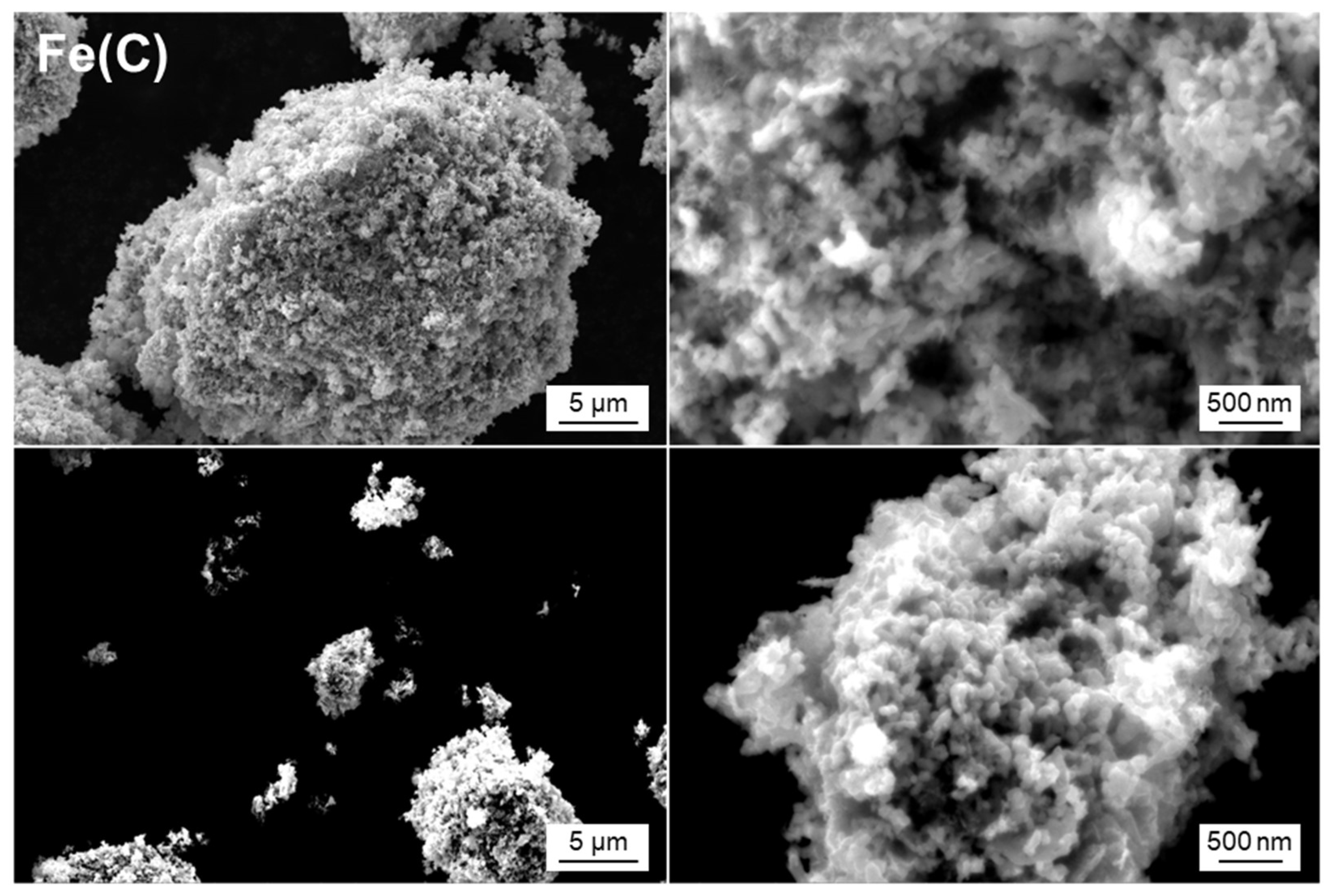
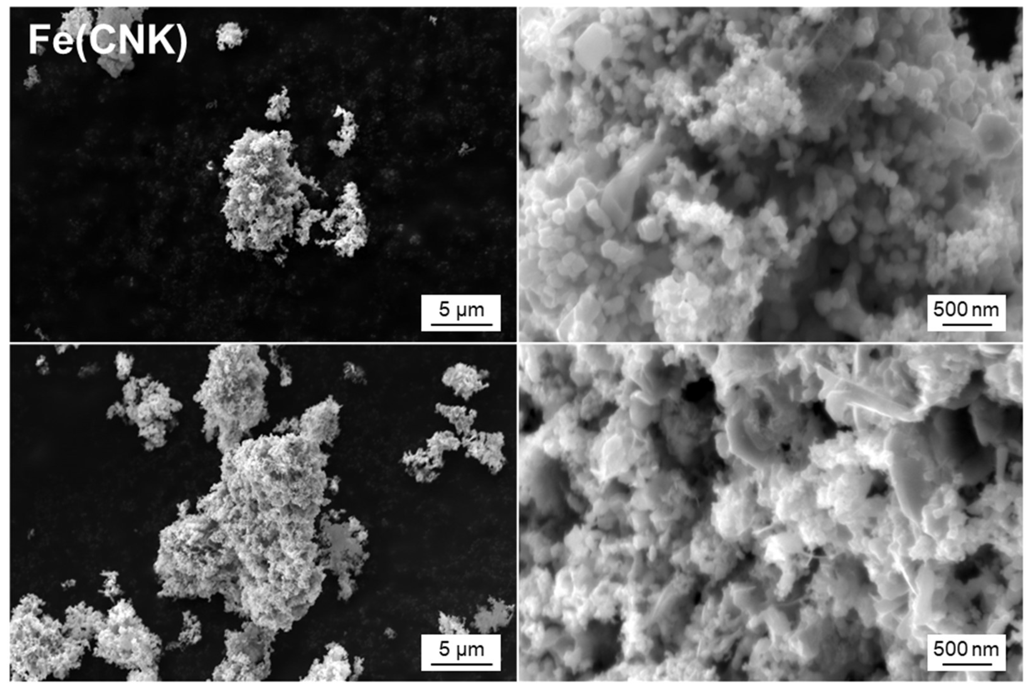
The morphologies of the commercial Fe2O3, Fe(C), Fe(CNK), and Fe(NK) were observed by SEM. The obtained SEM images are shown in Figure S1 and Figure 2, Figure 3 and Figure 4, respectively. For the commercial Fe2O3, irregular lumps were observed over the micron-sized vision, but it was confirmed that the lumps were composed of nanoscale flakes and particles of <500 nm. For both Fe(C) and Fe(CNK), more fine and fluffy appearances were observed in the micron-sized vision. In magnified visions, Fe(C) seemed composed of very small flakes and particles of <100 nm, whereas Fe(CNK) included larger and more grown particles than Fe(C). The difference in appearance could be due to the effect of molten salt in the preparation conditions. On the other hand, apart from the commercial Fe2O3, Fe(C), and Fe(CNK), very large particles of >500 nm with good crystallinity were observed for Fe(NK). Thus, the morphology seemed to grow into a thermodynamically stable, large spherical shape in the molten salt. In sum, the reduced iron nanoparticles and NaFeO2 nanoparticles were matured to improve their crystallinity and to increase their size in the molten salt for Fe(CNK) and Fe(NK).
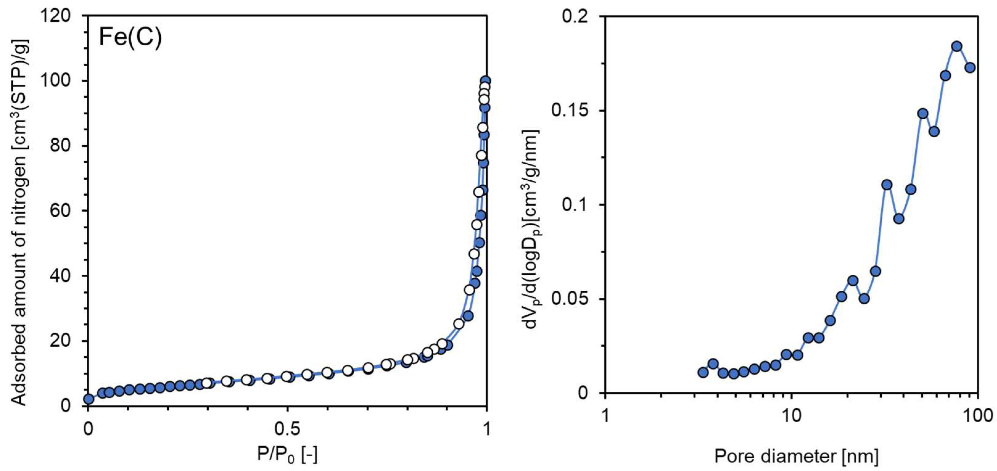
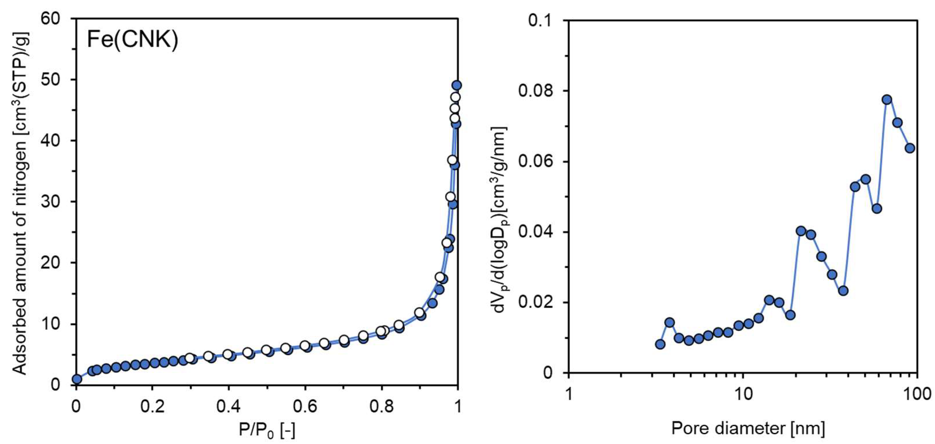
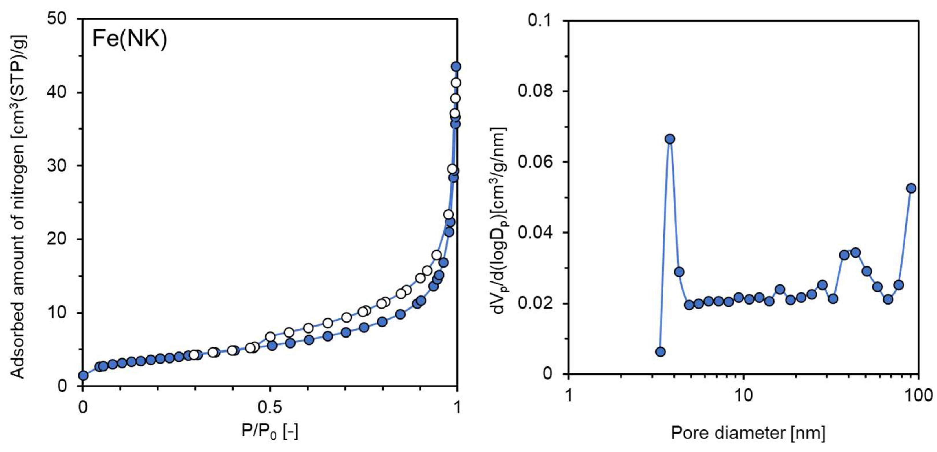
Porosities were evaluated by nitrogen adsorption and desorption experiments for the commercial Fe2O3, Fe(C), Fe(CNK), and Fe(NK). The obtained isotherms and pore size distributions are shown in Figure S2 and Figure 5, Figure 6 and Figure 7, respectively. The calculated BET surfaces and pore volumes are summarized in Table 1. The order of the BET surfaces was Fe(C) > Fe(CNK) > commercial Fe2O3. The results indicated that the porosities of samples improved following the reduction treatments. Because the reduction temperature of 220 °C with a strong CaH2 reducing agent is quite low in comparison with the general hydrogen reduction of >500 °C, diffusion of the reduced iron is slow, and its aggregation is prevented in such a low temperature, giving rise to nanostructured products. The BET surface area (13.6 m2/g) of Fe(CNK) was lower than 22.5 m2/g of Fe(C). Since the formation of more crystalized and larger nanoparticles was exhibited in Fe(CNK) compared to Fe(C) from the results of XRD measurements and SEM observations, the decrease in surface area could be due to the crystal growth in reduced iron nanoparticles in molten NaOH-KOH for Fe(CNK). Hysteresis between adsorption and desorption isotherms, which commonly indicates the formation of mesopores with high BET surface areas in the measured samples, was not observed for the commercial Fe2O3, Fe(C), and Fe(CNK) (Figure S2 and Figure 5 and Figure 6). On the other hand, slight hysteresis and the existence of small pores of 3.8 nm were shown for Fe(NK) in Figure 7. However, the BET surface area (13.7 m2/g) and pore volume (0.046 cm3/g) of Fe(NK) were both small, so the suggested pore structure was little occupied and the major morphology was nonporous spherical for Fe(NK), as observed in the SEM images.
Table 2 summarizes the representative BET surface areas of reported unsupported nanoscale zero-valent iron (nZVI). The high BET surface areas of >60 m2/g are reported in nZVI prepared by chemical reduction by a NaBH4 reducing agent. The reduction of Fe3+ or Fe2+ by NaBH4 in aqueous solutions is performed under ambient temperature and pressure, so the mild operating conditions are attractive for both laboratories and large-scale applications. One of the main drawbacks of the NaBH4 reduction method is the generation of a by-product (B(OH)3), resulting in secondary pollution when the iron ions are reduced. As the results of this study with the CaH2 reduction method, the BET surface areas of the obtained nZVI were smaller than those of previous studies, except for the case using the green synthesis method. An advantage of the CaH2 reduction method is that it releases no poisonous compounds but only nontoxic calcium species, such as CaO and Ca2+, thus validating it as a good environmentally friendly method [82,83,84,85].

3.2. Catalytic Tests with the Prepared Samples

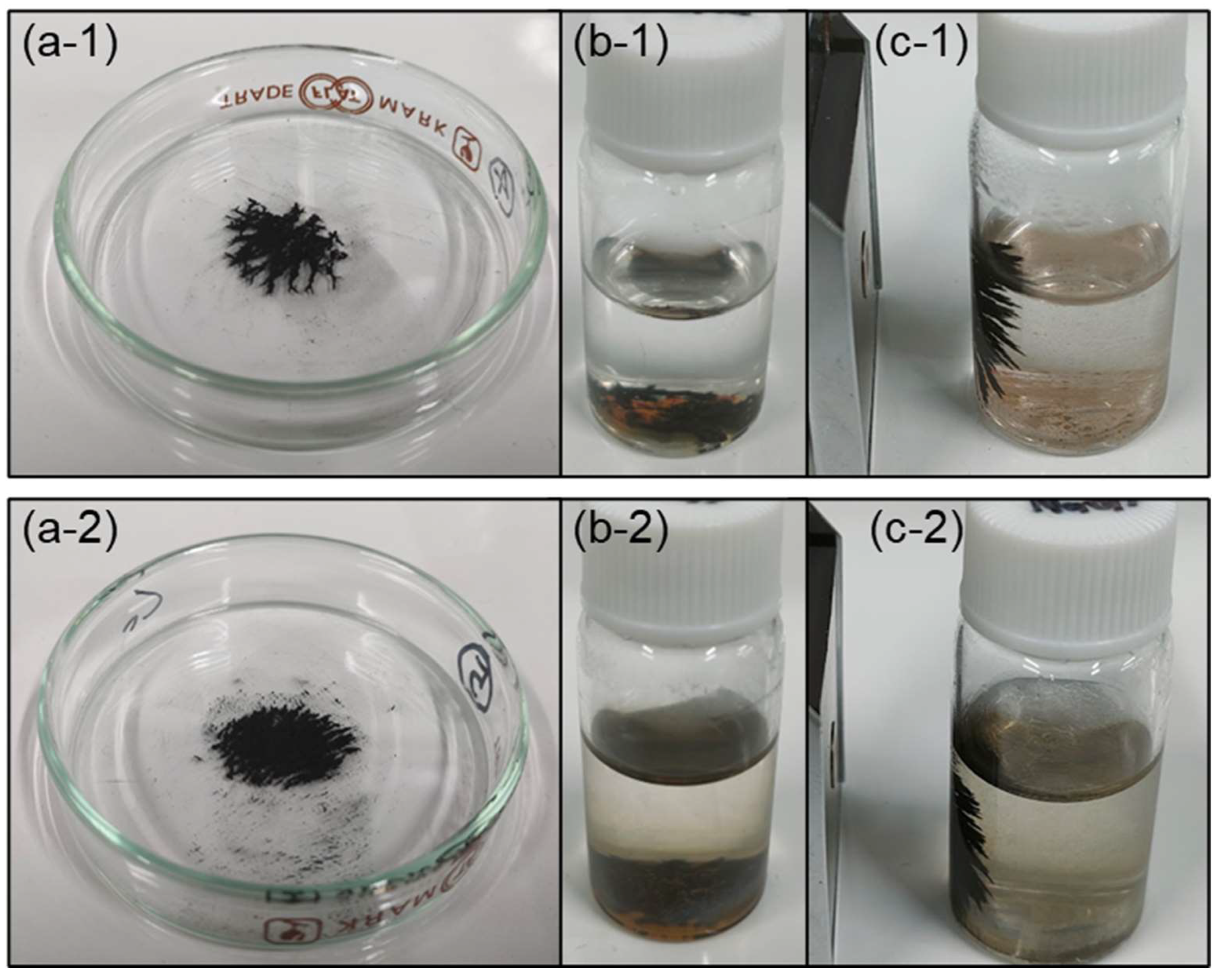
The catalytic performance of the prepared samples was evaluated in the liquid-phase hydrogenation of 4−NP. To confirm the stability and robustness of the samples, the samples that were water-soaked for 3 days were also tested for both Fe(C) and Fe(CNK). Figure 8 shows the appearance of the treated samples. After 3 days of exposing Fe(C) and Fe(CNK) to the atmosphere at room temperature, the samples’ color did not change and looked the same as the black color of the as-prepared Fe(C) and Fe(CNK), as shown in Figure 8(a-1),(a-2), respectively. On the other hand, for the water-soaked Fe(C) and Fe(CNK), the color of both samples seemed to partially change into a red color that corresponds to the color of iron oxides, such as Fe2O3, in Figure 8(b-1),(b-2), respectively. The soaked sample powders were attracted to magnets placed on the left side of sample bottles while the red-colored samples were left on the bottom (Figure 8c), suggesting that some of the samples could remain in the form of zero-valent iron.
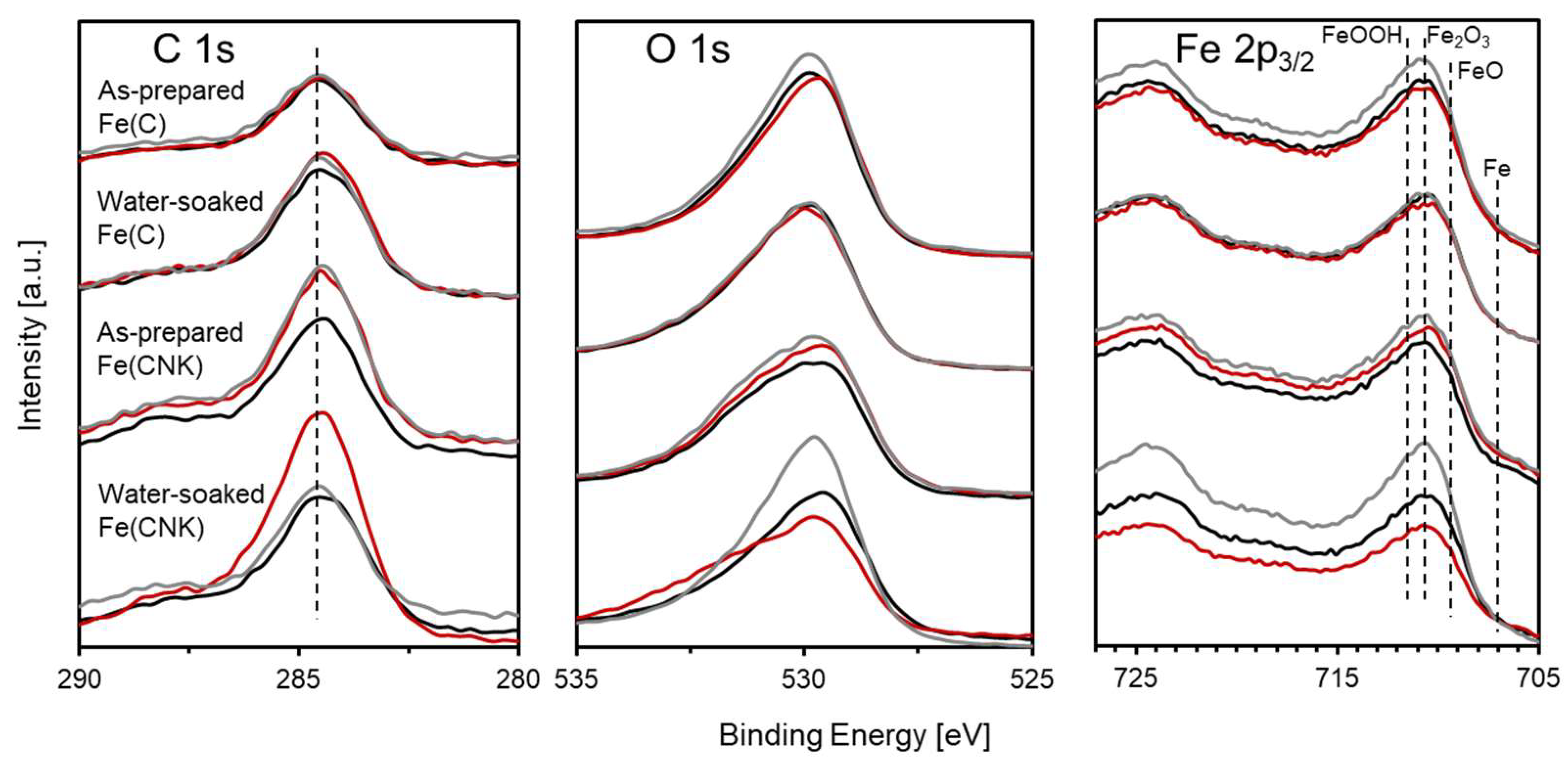
To examine the surface chemical states, XPS measurements were conducted for Fe(C) and Fe(CNK) with as-prepared and water-soaked conditions. The analyses were performed at three different positions for each sample to locate measurement errors. The obtained spectra for C 1s, O 1s, and Fe 2p3/2 orbitals and the surface molar ratios of oxygen and iron are described in Figure 9 and Table 3, respectively. Clear signals for O 1s orbitals were observed in all the samples. Quite large molar ratios of oxygen were detected in all the samples, indicating that most of the surfaces comprised oxides or/and hydroxides. For Fe 2p orbitals, signals that were assignable to metallic iron were little observed at a low binding energy, and instead, the broad signals corresponding to oxides (FeO, Fe2O3) and FeOOH were identified in all samples. The results indicated that the oxide films could not only form on water-soaked samples but also formed on the as-prepared samples. Perhaps the thickness of the oxide films was different between the as-prepared and water-soaked samples, and the former had thinner oxide films than the latter samples, which were mostly oxidized.
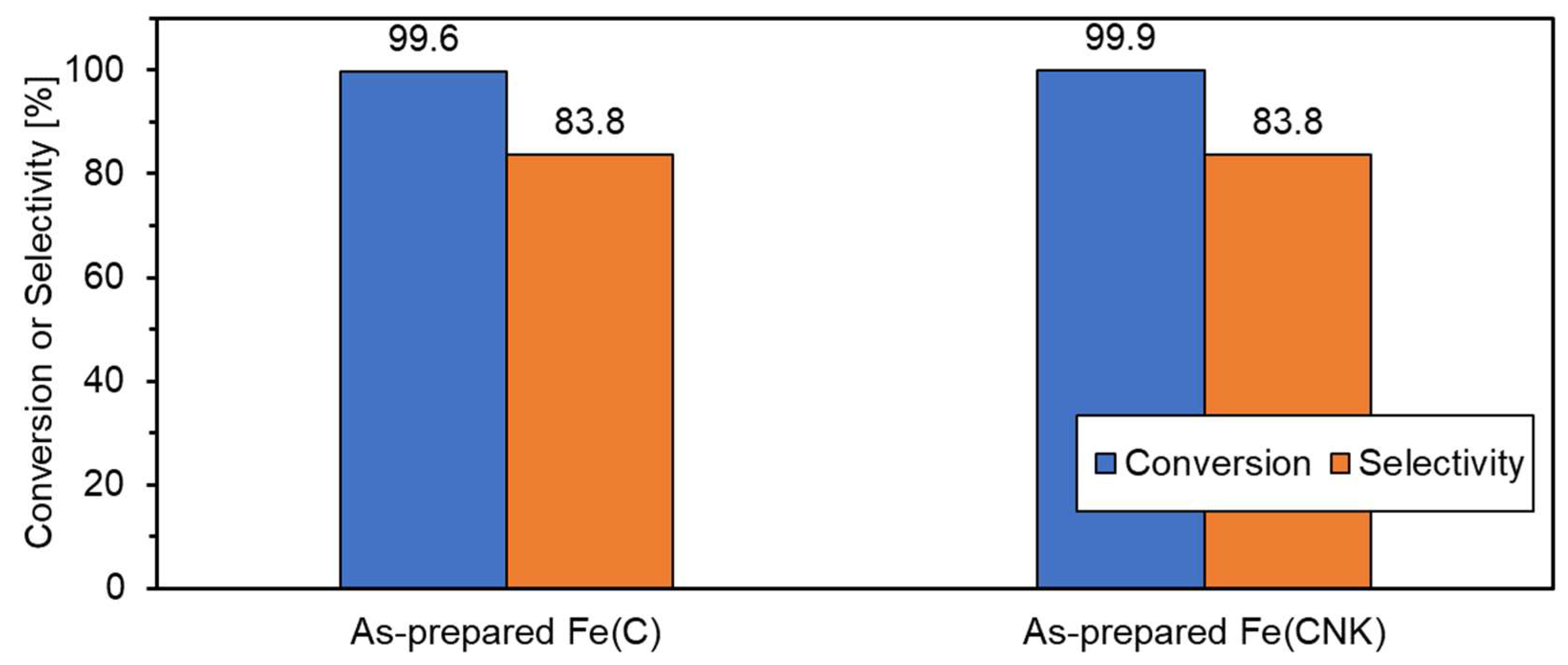
Figure 10 shows the reaction time depending on changes in absorbances corresponding to 4−NP (401 nm) and 4−AP (313 nm) for the as-prepared and water-soaked samples. Figure 11a shows the concentration changes of 4−NP during the reactions, which were obtained from the absorbance changes in Figure 10. As for the as-prepared Fe(C) and Fe(CNK), the absorbances at 401 nm gradually decreased and approached zero for 60 min. At the same time, the absorbances at 313 nm increased due to the decrease in absorbances at 401 nm. The selectivities from 4−NP to 4−AP after 60 min were 83.6% for both samples, which were calculated using calibration curves obtained at 313 nm (Figure 12). The results suggested that most of the 4−NP reactants were converted to 4−AP with few byproducts. In the initial stage of the reactions at 0–10 min, the decreasing changes in concentrations were almost the same as those of the as-prepared Fe(C) and Fe(CNK), as shown in Figure 11a. However, after the stage, the as-prepared Fe(CNK) showed a quicker drop in the concentration than the as-prepared Fe(C), and zero concentrations were obtained at 30 min and 60 min with the as-prepared Fe(CNK) and Fe(C), respectively. It quite interesting that the low surface area Fe(CNK) showed a higher catalytic performance than the high surface area Fe(C). This could be because the surface of Fe(CNK) was more activated during the annealing treatment in molten NaOH-KOH than the surface of Fe(C) that was formed by the reduction treatment by CaH2. Thus, the molten salt reduction was a superior approach to obtain the more active surface that is available for the catalytic hydrogenation.
Next, the water-soaked samples were tested under the same reaction conditions. Contrary to the results with as-prepared samples, the absorbances at 401 nm were slightly decreased and did not come close to zero over 60 min for the water-soaked Fe(C) and Fe(CNK), as shown in Figure 10. The absorbances at 313 nm were also little changed with the water-soaked samples. The results exhibited lower catalytic performances in the water-soaked samples than the as-prepared samples, and thus it was confirmed that Fe(C) and Fe(CNK) were deactivated by the previous water-soaking treatment for 3 days. Figure 11b shows the plots of ln (C/C0) versus the initial reaction time for Fe(C) and Fe(CNK) with the as-prepared and water-soaked conditions, where C is the time-changing concentration and C0 is the initial concentration of 4−NP. With a first-order assumption, reaction rate constants (k) of the separate samples were obtained from the gradient values of plots. The values are summarized in Table 4, together with those of previous works for comparison. The k values of the as-prepared samples were 0.040–0.048 min−1, whereas those of the water-soaked samples were 0.023–0.026 min−1. Thus, the k values were dramatically decreased by the previous water-soaking treatment due to the deactivation of the surface. In comparison with previous works, although it is not easy to fairly compare the catalytic activities due to the difference in the reaction conditions, our k values are comparable with those of unsupported FeAg and FeNi2, but the higher k values are reported by nanoscale zero-valent irons stabilized by bentonite clay and chitosan. Thus, it could be important to stabilize the prepared nano-iron to obtain a high catalytic performance in liquid-phase reactions. In conclusion, it was verified that the nanoscale zero-valent irons, or nZVI, prepared in this study can be available in liquid-phase hydrogenation reactions, and the proposed CaH2-assisted reduction method is a good approach to the cleaner preparation of nZVI.

4. Conclusions

Nanoscale zero-valent irons were obtained by reducing Fe2O3, which is a main component of iron ore, using a CaH2 reducing agent at 220 °C. The reduced sample was perfectly identified as single-phase nanoscale zero-valent iron with a BET surface area of 22.5 m2/g. The sample prepared with a combination of CaH2 and molten NaOH-KOH also showed a single phase with 13.6 m2/g. The molten salt was affected to form a stable spherical morphology. Both the samples showed good catalytic performances in the liquid-phase hydrogenation of 4−NP. Previous water-soaking treatment deactivated the prepared samples, indicating the importance of stabilizing the prepared samples when used in liquid-phase applications.

Supplementary Materials

The following supporting information can be downloaded at: https://www.mdpi.com/article/10.3390/min13111385/s1, Figure S1: SEM images for commercial Fe2O3; Figure S2: (left) Adsorption (blue) and desorption (white) isotherms of nitrogen and (right) pore size distribution for commercial Fe2O3.

Author Contributions

Conceptualization, Y.K.; methodology, Y.K. and K.Y.; validation, Y.K.; formal analysis, Y.K.; investigation, Y.K. and R.S.; resources, Y.K. and R.S.; data curation, Y.K. and K.Y.; writing—original draft preparation, Y.K.; writing—review and editing, Y.K., K.Y. and R.S.; visualization, Y.K.; supervision, Y.K.; project administration, Y.K.; funding acquisition, Y.K. and R.S. All authors have read and agreed to the published version of the manuscript.

Funding

This research was funded by the Japan Society for the Promotion of Science (JSPS), grant number 21K14465.

Data Availability Statement

Not applicable.

Acknowledgments

The authors thank Masanao Narita at the Renewable Energy Research Centre, National Institute of Advanced Industrial Science and Technology for SEM observations.

Conflicts of Interest

The authors declare no conflict of interest.

References

  1. Hasanbeigi, A.; Arens, M.; Price, L. Alternative emerging ironmaking technologies for energy-efficiency and carbon dioxide emissions reduction: A technical review. Renew. Sust. Energ. Rev. 2014, 33, 645–658. [Google Scholar] [CrossRef]
  2. Fan, Z.; Friedmann, S.J. Low-carbon production of iron and steel: Technology options, economic assessment, and policy. Joule 2021, 5, 829–862. [Google Scholar] [CrossRef]
  3. Spreitzer, D.; Schenk, J. Reduction of Iron Oxides with Hydrogen—A Review. Steel Res. Int. 2019, 90, 1900108. [Google Scholar] [CrossRef]
  4. Tang, J.; Chu, M.; Li, F.; Feng, C.; Liu, Z.; Zhou, Y. Development and progress on hydrogen metallurgy. Int. J. Miner. Metall. Mater. 2020, 27, 713–723. [Google Scholar] [CrossRef]
  5. Bhaskar, A.; Assadi, M.; Somehsaraei, H.N. Decarbonization of the Iron and Steel Industry with Direct Reduction of Iron Ore with Green Hydrogen. Energies 2020, 13, 758. [Google Scholar] [CrossRef]
  6. Liu, W.; Zuo, H.; Wang, J.; Xue, Q.; Ren, B.; Yang, F. The production and application of hydrogen in steel industry. Int. J. Hydrog. Energy 2021, 46, 10548–10569. [Google Scholar] [CrossRef]
  7. Li, S.; Zhang, H.; Nie, J.; Dewil, R.; Baeyens, J.; Deng, Y. The Direct Reduction of Iron Ore with Hydrogen. Sustainability 2021, 13, 8866. [Google Scholar] [CrossRef]
  8. Lan, C.; Hao, Y.; Shao, J.; Zhang, S.; Liu, R.; Lyu, Q. Effect of H2 on Blast Furnace Ironmaking: A Review. Metals 2022, 12, 1864. [Google Scholar] [CrossRef]
  9. Sastri, M.V.C.; Viswanath, R.P.; Viswanathan, B. Studies on the reduction of iron oxide with hydrogen. Int. J. Hydrog. Energy 1982, 7, 951–955. [Google Scholar] [CrossRef]
  10. Lin, H.; Chena, Y.; Li, C. The mechanism of reduction of iron oxide by hydrogen. Thermochim. Acta 2003, 400, 61–67. [Google Scholar] [CrossRef]
  11. Pineau, A.; Kanari, N.; Gaballah, I. Kinetics of reduction of iron oxides by H2 Part I: Low temperature reduction of hematite. Thermochim. Acta 2006, 447, 89–100. [Google Scholar] [CrossRef]
  12. Jung, S.; Lee, J. In-Situ Kinetic Study of Hydrogen Reduction of Fe2O3 for the Production of Fe Nanopowder. Mater. Trans. 2009, 50, 2270–2276. [Google Scholar] [CrossRef]
  13. Liang, M.; Kang, W.; Xie, K. Comparison of reduction behavior of Fe2O3, ZnO and ZnFe2O4 by TPR technique. J. Nat. Gas Chem. 2009, 18, 110–113. [Google Scholar] [CrossRef]
  14. Hou, B.; Zhang, H.; Li, H.; Zhu, Q. Study on Kinetics of Iron Oxide Reduction by Hydrogen. Chin. J. Chem. Eng. 2012, 20, 10–17. [Google Scholar] [CrossRef]
  15. Lee, G.; Choi, J.; Song, J.; Jung, S.; Lee, J. The Kinetics of Isothermal Hydrogen Reduction of Nanocrystalline Fe2O3 Powder. Mater. Trans. 2014, 55, 1611–1617. [Google Scholar] [CrossRef]
  16. Barde, A.A.; Klausner, J.F.; Mei, R. Solid state reaction kinetics of iron oxide reduction using hydrogen as a reducing agent. Int. J. Hydrog. Energy 2016, 41, 10103–10119. [Google Scholar] [CrossRef]
  17. Brandner, U.; Leuchtenmueller, M. Comparison of reduction kinetics of Fe2O3, ZnOFe2O3 and ZnO with hydrogen (H2) and carbon monoxide (CO). Int. J. Hydrog. Energy 2023, in press. [Google Scholar] [CrossRef]
  18. Wimmers, O.J.; Arnoldy, P.; Moulijn, J.A. Determination of the Reduction Mechanism by Temperature-Programmed Reduction: Application to Small Fe2O3 Particles. J. Phys. Chem. 1986, 90, 1331–1337. [Google Scholar] [CrossRef]
  19. Zielinski, J.; Zglinicka, I.; Znak, L.; Kaszkur, Z. Reduction of Fe2O3 with hydrogen. Appl. Catal. A Gen. 2010, 381, 191–196. [Google Scholar] [CrossRef]
  20. Yamamoto, S.; Ruwan, G.; Tamada, Y.; Kohara, K.; Kusano, Y.; Sasano, T.; Ohno, K.; Tsujii, Y.; Kageyama, H.; Ono, T.; et al. Transformation of Nano- to Mesosized Iron Oxide Cores to r-Fe within Organic Shells Preserved Intact. Chem. Mater. 2011, 23, 1564–1569. [Google Scholar] [CrossRef]
  21. Kohara, K.; Yamamoto, S.; Seinberg, L.; Murakami, T.; Tsujimoto, M.; Ogawa, T.; Kurata, H.; Kageyama, H.; Takano, M. Carboxylated SiO2-coated a-Fe nanoparticles: Towards a versatile platform for biomedical applications. Chem. Commun. 2013, 49, 2563–2565. [Google Scholar] [CrossRef] [PubMed]
  22. Seinberg, L.; Yamamoto, S.; Tsujimoto, M.; Kobayashi, Y.; Takano, M.; Kageyama, H. CaH2-assisted low temperature synthesis of metallic magnetic nanoparticle-loaded multiwalled carbon nanotubes. Chem. Commun. 2014, 50, 6866–6868. [Google Scholar] [CrossRef]
  23. Yamamoto, S.; Tsujimoto, M. Well-defined SiO2-coated Fe2Co nanoparticles prepared by reduction with CaH2. RSC Adv. 2015, 5, 100084–100088. [Google Scholar] [CrossRef]
  24. Tsuchida, T.; Fukushima, J.; Tobise, M.; Hayashi, Y.; Takizawa, H. Low-temperature hydrogen reduction of iron oxide by controlling the water potential using a CaH2 drying agent. J. Solid State Chem. 2021, 302, 122441. [Google Scholar] [CrossRef]
  25. Nurmi, J.T.; Tratnyek, P.G.; Sarathy, V.; Baer, D.R.; Amonette, J.E.; Pecher, K.; Wang, C.; Linehan, J.C.; Matson, D.W.; Penn, R.L.; et al. Characterization and Properties of Metallic Iron Nanoparticles:  Spectroscopy, Electrochemistry, and Kinetics. Environ. Sci. Technol. 2005, 39, 1221–1230. [Google Scholar] [CrossRef] [PubMed]
  26. Li, X.; Elliott, D.W.; Zhang, W. Zero-Valent Iron Nanoparticles for Abatement of Environmental Pollutants: Materials and Engineering Aspects. Crit. Rev. Solid State Mater. 2006, 31, 111–122. [Google Scholar] [CrossRef]
  27. Mueller, N.C.; Braun, J.; Bruns, J.; Černík, M.; Rissing, P.; Rickerby, D.; Nowack, B. Application of nanoscale zero valent iron (NZVI) for groundwater remediation in Europe. Environ. Sci. Pollut. Res. 2012, 19, 550–558. [Google Scholar] [CrossRef]
  28. Crane, R.A.; Scott, T.B. Nanoscale zero-valent iron: Future prospects for an emerging water treatment technology. J. Hazard. Mater. 2012, 211, 112–125. [Google Scholar] [CrossRef]
  29. O’Carroll, D.; Sleep, B.; Krol, M.; Boparai, H.; Kocur, C. Nanoscale zero valent iron and bimetallic particles for contaminated site remediation. Adv. Water Resour. 2013, 51, 104–122. [Google Scholar] [CrossRef]
  30. Tang, H.; Wang, J.; Zhang, S.; Pang, H.; Wang, X.; Chen, Z.; Li, M.; Song, G.; Qiu, M.; Yu, S. Recent advances in nanoscale zero-valent iron-based materials: Characteristics, environmental remediation and challenges. J. Clean. Prod. 2021, 319, 128. [Google Scholar] [CrossRef]
  31. Li, Q.; Chen, Z.; Wang, H.; Yang, H.; Wen, T.; Wang, S.; Hu, B.; Wang, X. Removal of organic compounds by nanoscale zero-valent iron and its composites. Sci. Total Environ. 2021, 792, 148546. [Google Scholar] [CrossRef] [PubMed]
  32. Jiang, D.; Zeng, G.; Huang, D.; Chen, M.; Zhang, C.; Huang, C.; Wan, J. Remediation of contaminated soils by enhanced nanoscale zero valent iron. Environ. Res. 2018, 163, 217–227. [Google Scholar] [CrossRef]
  33. Xue, W.; Huang, D.; Zeng, G.; Wan, J.; Cheng, M.; Zhang, C.; Hu, C.; Li, J. Performance and toxicity assessment of nanoscale zero valent iron particles in the remediation of contaminated soil: A review. Chemosphere 2018, 210, 1145–1156. [Google Scholar] [CrossRef]
  34. Tosco, T.; Papini, M.P.; Viggi, C.C.; Sethi, R. Nanoscale zerovalent iron particles for groundwater remediation: A review. J. Clean. Prod. 2014, 77, 10–21. [Google Scholar] [CrossRef]
  35. Fu, F.; Dionysiou, D.D.; Liu, H. The use of zero-valent iron for groundwater remediation and wastewater treatment: A review. J. Hazard. Mater. 2014, 267, 194–205. [Google Scholar] [CrossRef]
  36. Raman, C.D.; Kanmani, S. Textile dye degradation using nano zero valent iron: A review. J. Environ. Manag. 2016, 177, 341–355. [Google Scholar] [CrossRef] [PubMed]
  37. Zou, Y.; Wang, X.; Khan, A.; Wang, P.; Liu, Y.; Alsaedi, A.; Hayat, T.; Wang, X. Environmental Remediation and Application of Nanoscale Zero-Valent Iron and Its Composites for the Removal of Heavy Metal Ions: A Review. Environ. Sci. Technol. 2016, 50, 7290–7304. [Google Scholar] [CrossRef]
  38. Pasinszki, T.; Krebsz, M. Synthesis and Application of Zero-Valent Iron Nanoparticles in Water Treatment, Environmental Remediation, Catalysis, and Their Biological Effects. Nanomaterials 2020, 10, 917. [Google Scholar] [CrossRef] [PubMed]
  39. Lu, H.; Wang, J.; Ferguson, S.; Wang, T.; Bao, Y.; Hao, H. Mechanism, synthesis and modification of nano zerovalent iron in water treatment. Nanoscale 2016, 8, 9962–9975. [Google Scholar] [CrossRef] [PubMed]
  40. Mukherjee, R.; Kumar, R.; Sinha, A.; Lama, Y.; Saha, A.K. A review on synthesis, characterization, and applications of nano zero valent iron (nZVI) for environmental remediation. Crit. Rev. Environ. Sci. Technol. 2016, 46, 443–466. [Google Scholar] [CrossRef]
  41. Adusei-Gyamfia, J.; Acha, V. Carriers for nano zerovalent iron (nZVI): Synthesis, application and efficiency. RSC Adv. 2016, 6, 91025–91044. [Google Scholar] [CrossRef]
  42. Stefaniuk, M.; Oleszczuk, P.; Ok, Y.S. Review on nano zerovalent iron (nZVI): From synthesis to environmental applications. Chem. Eng. J. 2016, 287, 618–632. [Google Scholar] [CrossRef]
  43. Li, S.; Yan, W.; Zhang, W. Solvent-free production of nanoscale zero-valent iron (nZVI) with precision milling. Green Chem. 2009, 11, 1618–1626. [Google Scholar] [CrossRef]
  44. Wang, P.; Hu, J.; Liu, T.; Han, G.; Ma, W.; Li, J. New insights into ball-milled zero-valent iron composites for pollution remediation: An overview. J. Clean. Prod. 2023, 385, 135513. [Google Scholar] [CrossRef]
  45. Okazoe, S.; Yasaka, Y.; Kudo, M.; Maeno, H.; Murakami, Y.; Kimura, Y. Synthesis of zero-valent iron nanoparticles via laser ablation in a formate ionic liquid under atmospheric conditions. Chem. Commun. 2018, 54, 7834–7837. [Google Scholar] [CrossRef]
  46. Wang, C.; Zhang, W. Synthesizing Nanoscale Iron Particles for Rapid and Complete Dechlorination of TCE and PCBs. Environ. Sci. Technol. 1997, 31, 2154–2156. [Google Scholar] [CrossRef]
  47. Wang, Q.; Snyder, S.; Kim, J.; Choi, H. Aqueous Ethanol modified Nanoscale Zerovalent Iron in Bromate Reduction: Synthesis, Characterization, and Reactivity. Environ. Sci. Technol. 2009, 43, 3292–3299. [Google Scholar] [CrossRef]
  48. Wang, Q.; Kanel, S.R.; Park, H.; Ryu, A.; Choi, H. Controllable synthesis, characterization, and magnetic properties of nanoscale zerovalent iron with specific high Brunauer–Emmett–Teller surface area. J. Nanopart. Res. 2009, 11, 749–755. [Google Scholar] [CrossRef]
  49. Hwang, Y.; Kim, D.; Shin, H. Effects of synthesis conditions on the characteristics and reactivity of nano scale zero valent iron. Appl. Catal. B Environ. 2011, 105, 144–150. [Google Scholar] [CrossRef]
  50. Yuvakkumar, R.; Elango, V.; Rajendran, V.; Kannan, N. Preparation and characterization of zero valent iron nanoparticles. Dig. J. Nanomater. Biostructures 2011, 6, 1771–1776. [Google Scholar]
  51. Jamei, M.R.; Khosravi, M.R.; Anvaripour, B. A novel ultrasound assisted method in synthesis of NZVI particles. Ultrason. Sonochem. 2014, 21, 226–233. [Google Scholar] [CrossRef] [PubMed]
  52. Hoch, L.B.; Mack, E.J.; Hydutsky, B.W.; Hershman, J.M.; Skluzacek, J.M.; Mallouk, T.E. Carbothermal Synthesis of Carbon-supported Nanoscale Zero-valent Iron Particles for the Remediation of Hexavalent Chromium. Environ. Sci. Technol. 2008, 42, 2600–2605. [Google Scholar] [CrossRef]
  53. Choi, C.J.; Tolochko, O.; Kim, B.K. Preparation of iron nanoparticles by chemical vapor condensation. Mater. Lett. 2002, 56, 289–294. [Google Scholar] [CrossRef]
  54. Sun, H.; Zhou, G.; Liu, S.; Ang, H.M.; Tade, M.O.; Wang, S. Nano-Fe0 Encapsulated in Microcarbon Spheres: Synthesis, Characterization, and Environmental Applications. ACS Appl. Mater. Interfaces 2012, 4, 6235–6241. [Google Scholar] [CrossRef] [PubMed]
  55. Joseyphus, R.J.; Kodama, D.; Matsumoto, T.; Sato, Y.; Jeyadevan, B.; Tohji, K. Role of polyol in the synthesis of Fe particles. J. Magn. Magn. Mater. 2007, 310, 2393–2395. [Google Scholar] [CrossRef]
  56. Joseyphus, R.J.; Shinoda, K.; Kodama, D.; Jeyadevan, B. Size controlled Fe nanoparticles through polyol process and their magnetic properties. Mater. Chem. Phys. 2010, 123, 487–493. [Google Scholar] [CrossRef]
  57. Chen, S.; Hsu, H.; Li, C. A new method to produce nanoscale iron for nitrate removal. J. Nanopart. Res. 2004, 6, 639–647. [Google Scholar] [CrossRef]
  58. Wang, X.; Yang, H.; Yu, X.; Hu, J.; Cheng, J.; Jing, H. Research progress in the preparation of iron by electrochemical reduction route without CO2 emissions. J. Appl. Electrochem. 2023, 53, 1521–1536. [Google Scholar] [CrossRef]
  59. Hoag, G.E.; Collins, J.B.; Holcomb, J.L.; Hoag, J.R.; Nadagouda, M.N.; Varma, R.S. Degradation of bromothymol blue by ‘greener’ nano-scale zero-valent iron synthesized using tea polyphenols. J. Mater. Chem. 2009, 19, 8671–8677. [Google Scholar] [CrossRef]
  60. Machado, S.; Pinto, S.L.; Grosso, J.P.; Nouws, H.P.A.; Albergaria, J.T.; Delerue-Matos, C. Green production of zero-valent iron nanoparticles using tree leaf extracts. Sci. Total Environ. 2013, 445, 1–8. [Google Scholar] [CrossRef]
  61. Huang, L.; Weng, X.; Chen, Z.; Megharaj, M.; Naidu, R. Green synthesis of iron nanoparticles by various tea extracts: Comparative study of the reactivity. Spectrochim. Acta A Mol. Biomol. Spectrosc. 2014, 130, 295–301. [Google Scholar] [CrossRef]
  62. Glavee, G.N.; Klabunde, K.J.; Sorensen, C.M.; Hadjipanayis, G.C. Chemistry of Borohydride Reduction of Iron(II) and Iron(III) Ions in Aqueous and Nonaqueous Media. Formation of Nanoscale Fe, FeB, and Fe2B Powders. Inorg. Chem. 1995, 34, 28–35. [Google Scholar] [CrossRef]
  63. Zhao, X.; Liu, W.; Cai, Z.; Han, B.; Qian, T.; Zhao, D. An overview of preparation and applications of stabilized zero-valent iron nanoparticles for soil and groundwater remediation. Water Res. 2016, 100, 245–266. [Google Scholar] [CrossRef] [PubMed]
  64. Yan, W.; Lien, H.; Koel, B.E.; Zhang, W. Iron nanoparticles for environmental clean-up: Recent developments and future outlook. Environ. Sci. Process. Impacts 2013, 15, 63–77. [Google Scholar] [CrossRef] [PubMed]
  65. Mu, Y.; Jia, F.; Ai, Z.; Zhang, L. Iron oxide shell mediated environmental remediation properties of nano zero-valent iron. Environ. Sci. Nano 2017, 4, 27–45. [Google Scholar] [CrossRef]
  66. Li, J.; Zhang, X.; Sun, Y.; Liang, L.; Pan, B.; Zhang, W.; Guan, X. Advances in Sulfidation of Zerovalent Iron for Water Decontamination. Environ. Sci. Technol. 2017, 51, 13533–13544. [Google Scholar] [CrossRef]
  67. Bae, S.; Collins, R.N.; Waite, T.D.; Hanna, K. Advances in Surface Passivation of Nanoscale Zerovalent Iron: A Critical Review. Environ. Sci. Technol. 2018, 52, 12010–12025. [Google Scholar] [CrossRef]
  68. Ken, D.S.; Sinha, A. Recent developments in surface modification of nano zero-valent iron (nZVI): Remediation, toxicity and environmental impacts. Environ. Nanotechnol. Monit. Manag. 2020, 14, 100344. [Google Scholar] [CrossRef]
  69. Ezzatahmadi, N.; Ayoko, G.A.; Millar, G.J.; Speight, R.; Yan, C.; Li, J.; Li, S.; Zhu, J.; Xi, Y. Clay-supported nanoscale zero-valent iron composite materials for the remediation of contaminated aqueous solutions: A review. Chem. Eng. J. 2017, 312, 336–350. [Google Scholar] [CrossRef]
  70. Wang, S.; Zhao, M.; Zhou, M.; Lia, Y.C.; Wang, J.; Gao, B.; Sato, S.; Feng, K.; Yin, W.; Igalavithana, A.D.; et al. Biochar-supported nZVI (nZVI/BC) for contaminant removal from soil and water: A critical review. J. Hazard. Mater. 2019, 373, 820–834. [Google Scholar] [CrossRef]
  71. Liang, W.; Wang, G.; Peng, C.; Tan, J.; Wan, J.; Sun, P.; Li, Q.; Ji, X.; Zhang, Q.; Wu, Y.; et al. Recent advances of carbon-based nano zero valent iron for heavy metals remediation in soil and water: A critical review. J. Hazard. Mater. 2022, 426, 127993. [Google Scholar] [CrossRef]
  72. Kobayashi, Y. Synthesis of Porous Ni3Al Intermetallic Nano-compounds in a Molten LiCl with Assistance of CaH2 as a Structure-controlling Agent. Chem. Lett. 2019, 48, 1496–1499. [Google Scholar] [CrossRef]
  73. Kobayashi, Y.; Suzuki, D.; Yokoyama, S.; Shoji, R. Molten salt synthesis of high-entropy alloy AlCoCrFeNiV nanoparticles for the catalytic hydrogenation of p-nitrophenol by NaBH4. Int. J. Hydrog. Energy 2022, 47, 3722–3732. [Google Scholar] [CrossRef]
  74. Kobayashi, Y.; Yokoyama, S.; Shoji, R. Molten salt synthesis of CrMnFeNi alloy nanopowder passivated by TiOx–ZrOy shell used as a superior catalyst support in liquid-phase hydrogenation. RSC Adv. 2023, 13, 10790–10799. [Google Scholar] [CrossRef] [PubMed]
  75. McAuliffe, R.D.; Kamm, G.E.; McDermott, M.J.; Hermann, R.P.; Vasquez-Garcia, N.; Sacci, R.L.; Persson, K.A.; Chapman, K.W.; Veith, G.M. Direct Mechanochemical Synthesis, Phase Stability, and Electrochemical Performance of α-NaFeO2. Inorg. Chem. 2023, 62, 3358–3367. [Google Scholar] [CrossRef]
  76. Gomez-García, J.F.; Pfeiffer, H. Effect of Chemical Composition and Crystal Phase of (Li,Na)FeO2 Ferrites on CO2 Capture Properties at High Temperatures. J. Phys. Chem. C 2018, 122, 21162–21171. [Google Scholar] [CrossRef]
  77. Yanase, I.; Onozawa, S.; Ogasawara, K.; Kobayashi, H. A novel application of α- and β-sodium ferrite as a CO2-capturing solid in air with water vapor. J. CO2 Util. 2018, 24, 200–209. [Google Scholar] [CrossRef]
  78. Yanase, I.; Onozawa, S.; Ohashi, Y.; Takeuchi, T. CO2 capture fromambient air by β-NaFeO2 in the presence ofwater vapor at 25–100 °C. Powder Technol. 2019, 348, 43–50. [Google Scholar] [CrossRef]
  79. Durai, L.; Gopalakrishnan, A.; Badhulika, S. One-step solid-state reaction synthesis of b-NaFeO2 nanopebble as high capacity cathode material for sodium ion batteries. Mater. Lett. 2020, 270, 127739. [Google Scholar] [CrossRef]
  80. Viret, M.; Rubi, D.; Colson, D.; Lebeugle, D.; Forget, A.; Bonville, P.; Dhalenne, G.; Saint-Martin, R.; Andre, G.; Ott, F. b-NaFeO2, a new room-temperature multiferroic material. Mater. Res. Bull. 2012, 47, 2294–2298. [Google Scholar] [CrossRef]
  81. Singh, S.; Tovstolytkin, A.; Lotey, G.S. Heating loss mechanism in β-NaFeO2 nanoparticles for cancer treatment under alternating field. Materialia 2021, 18, 101152. [Google Scholar] [CrossRef]
  82. Kobayashi, Y.; Teah, H.Y.; Hanada, N. Environmentally friendly chemical synthesis of intermetallic iron aluminide submicrometer particles. J. Clean. Prod. 2021, 316, 128264. [Google Scholar] [CrossRef]
  83. Kobayashi, Y.; Teah, H.Y.; Hanada, N. Chemical synthesis of unique intermetallic TiFe nanostructures originating from the morphology of oxide precursors. Nanoscale Adv. 2021, 3, 5284–5291. [Google Scholar] [CrossRef] [PubMed]
  84. Kobayashi, Y.; Teah, H.Y.; Yokoyama, S.; Shoji, R.; Hanada, N. Environmentally friendly molten salt synthesis of high-entropy AlCoCrFeNi alloy powder with high catalytic hydrogenation activity. Int. J. Hydrog. Energy 2023, 48, 30963–30973. [Google Scholar] [CrossRef]
  85. Kobayashi, Y.; Teah, H.Y.; Yokoyama, S.; Shoji, R.; Hanada, N. A Molten Salt Synthesis Method of the High-Entropy Alloy CrMnFeCoNi for High Catalytic Performance and Low Life Cycle GHG Emissions. ACS Sustain. Chem. Eng. 2022, 10, 15046–15057. [Google Scholar] [CrossRef]
  86. Kobayashi, Y.; Yokoyama, S.; Shoji, R. Core-Shell Multicomponent Alloys with High Specific Surface Areas Prepared by Molten Salt Synthesis for Catalytic Hydrogenation of p-Nitrophenol by NaBH4. ACS Appl. Eng. Mater. 2023, 1, 152–164. [Google Scholar] [CrossRef]
  87. Kobayashi, Y.; Yokoyama, S.; Shoji, R. Molten Salt Synthesis of Intermetallic Compound TiNi Nanopowder Prepared from NiTiO3 for Catalytic Hydrogenation. Materials 2022, 15, 8536. [Google Scholar] [CrossRef]
  88. Sravanthi, K.; Ayodhya, D.; Swamy, P.Y. Green synthesis, characterization and catalytic activity of 4-nitrophenol reduction and formation of benzimidazoles using bentonite supported zero valent iron nanoparticles. Mater. Sci. Energy Technol. 2019, 2, 298–307. [Google Scholar] [CrossRef]
  89. Bae, S.; Gim, S.; Kim, H.; Hanna, K. Effect of NaBH4 on properties of nanoscale zero-valent iron and its catalytic activity for reduction of p-nitrophenol. Appl. Catal. B Enviro. 2016, 182, 541–549. [Google Scholar] [CrossRef]
  90. Lu, H.; Qiao, X.; Wang, W.; Tan, F.; Xiao, Z.; Chen, J. Chitosan stabilised nanozero-valent iron for the catalytic reduction of p-nitrophenol. Micro Nano Lett. 2014, 9, 446–450. [Google Scholar] [CrossRef]
  91. Malik, M.A.; Alshehri, A.A.; Patel, R. Facile one-pot green synthesis of Ag-Fe bimetallic nanoparticles and their catalytic capability for 4-nitrophenol reduction. J. Mater. Res. Technol. 2021, 12, 455–470. [Google Scholar] [CrossRef]
  92. Wu, K.; Yu, R.; Wei, X. Monodispersed FeNi2 alloy nanostructures: Solvothermal synthesis, magnetic properties and size-dependent catalytic activity. CrystEngComm 2012, 14, 7626–7632. [Google Scholar] [CrossRef]
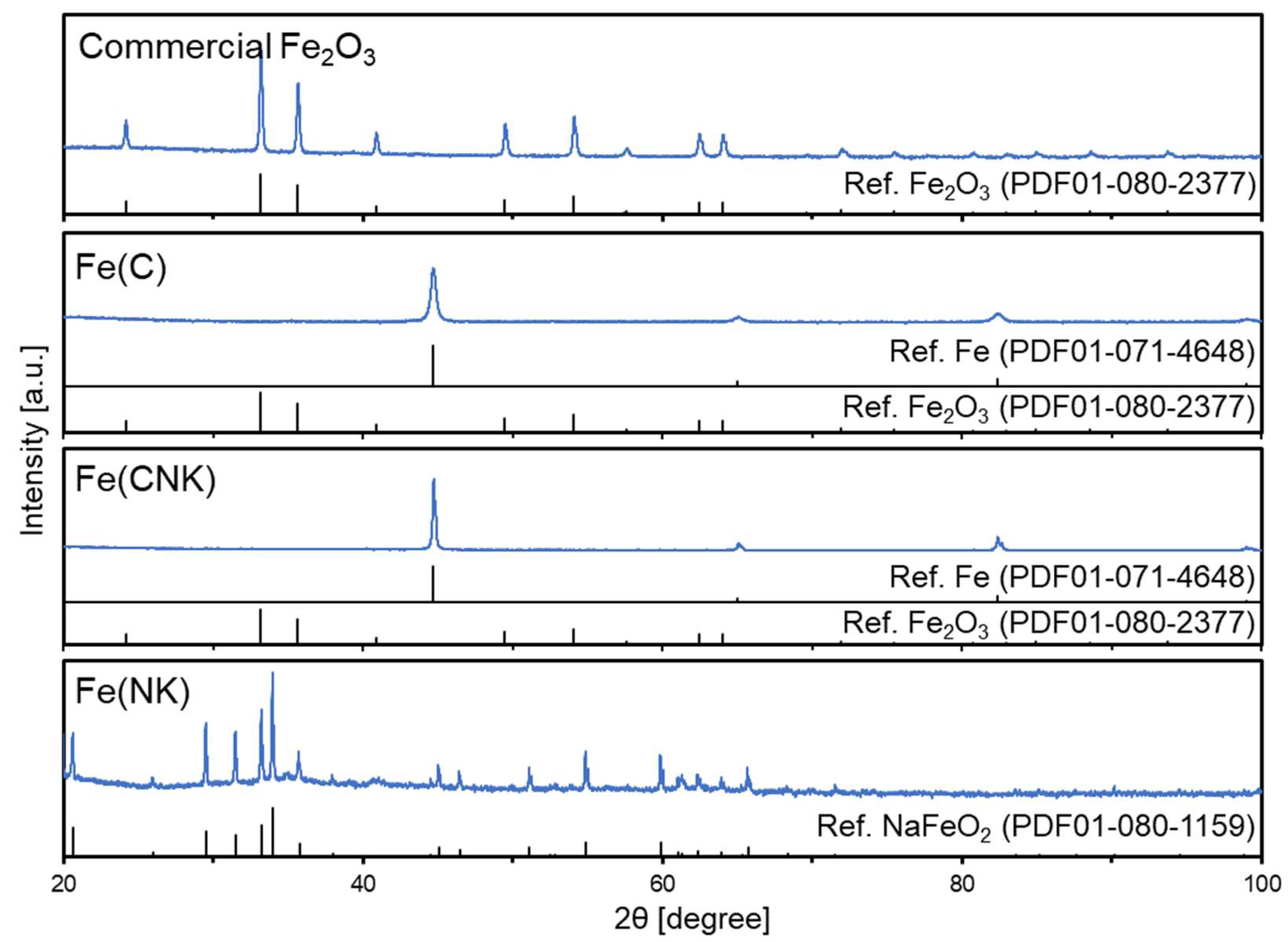
Figure 1. XRD patterns for commercial Fe2O3 and the prepared samples.
Minerals 13 01385 g001
Figure 2. SEM images for Fe(C).
Minerals 13 01385 g002
Figure 3. SEM images for Fe(CNK).
Minerals 13 01385 g003
Figure 4. SEM images for Fe(NK).
Minerals 13 01385 g004
Figure 5. (left) Adsorption (blue) and desorption (white) isotherms of nitrogen and (right) pore size distribution for Fe©.
Minerals 13 01385 g005
Figure 6. (left) Adsorption (blue) and desorption (white) isotherms of nitrogen and (right) pore size distribution for Fe(CNK).
Minerals 13 01385 g006
Figure 7. (left) Adsorption (blue) and desorption (white) isotherms of nitrogen and (right) pore size distribution for Fe(NK).
Minerals 13 01385 g007
Figure 8. Appearances of the samples of (a) air-exposed for 3 days, (b) water-soaked for 3 days, and (c) magnetic properties shown when magnets were placed next to the sample bottles for (1) Fe(C) and (2) Fe(CNK).
Minerals 13 01385 g008
Figure 9. XPS spectra of C 1s, O 1s, and Fe 2p3/2 orbitals for Fe(C) and Fe(CNK) with as-prepared and water-soaked conditions. Data were measured at three different positions, expressed by gray, black and red lines.
Minerals 13 01385 g009
Figure 10. Absorbance of a series of 4−NP solutions with a change in reaction time for Fe(C) and Fe(CNK) with as-prepared and water-soaked conditions.
Minerals 13 01385 g010
Figure 11. (a) Changes in 4−NP concentration versus reaction time, and (b) the plots of ln (C/C0) versus initial reaction time for Fe(C) and Fe(CNK) with as-prepared and water-soaked conditions, where C is the time-changing concentration and C0 is the initial concentration of 4−NP. Equations obtained with linear approximation are shown in the figures.
Minerals 13 01385 g011
Figure 12. Conversion of 4−NP and selectivity to 4−AP after 60 min reactions for as-prepared Fe(C) and as-prepared Fe(CNK).
Minerals 13 01385 g012
Table 1. Preparation conditions, and the results of XRD measurements and N2 adsorption experiments for commercial Fe2O3 and the prepared samples.
Sample NamePreparation ConditionsXRDN2 Adsorption
Reducing
Agent
Molten
Salt
Reduction Temp. [°C]Identified Fe CompoundCrystallite
Size [nm] *
BET Surface Area [m2/g]Pore Volume
[cm3/g]
Commercial Fe2O3NoneNoneNoneFe2O35210.50.118
Fe(C)CaH2None220Fe2422.50.116
Fe(CNK)CaH2NaOH-KOH220Fe6413.60.056
Fe(NK)NoneNaOH-KOH220β-NaFeO210513.70.046
* Calculated by the Scherrer equation based on the peak observed at 2θ = 33.2°, 44.7°, and 44.0° for Fe2O3, Fe, and NaFeO2, respectively.
Table 2. Summary of representative BET surface areas of reported unsupported nZVI.
BET Surface Area [m2/g]Preparation MethodReference
39Precision milling[43]
33.5Liquid reduction with NaBH4[46]
26.58[50]
45.4[49]
62.48[48]
67.51[47]
42Ultrasound assisted reduction with NaBH4[51]
25.4Electrochemical[57]
5.8Green synthesis[61]
Table 3. Molar ratios of oxygen and iron by XPS measurements for Fe(C) and Fe(CNK) with as-prepared and water-soaked conditions. Each value is an average value of three measurements.
Sample NameMolar Ratio [mol%]
OFe
As-prepared Fe(C)78.521.5
Water-soaked Fe(C)81.918.1
As-prepared Fe(CNK)84.415.6
Water-soaked Fe(CNK)79.920.1
Table 4. Comparison of rate constants (k) in hydrogenation of 4−NP at various reaction conditions among previous and present studies.
SampleBET Surface Area [m2/g]Reaction Conditionsk [min−1]Reference
As-prepared Fe(C)22.525 °C
4−NP (1.6 mM)
NaBH4 (47 mM)
10 mg−cat/9 mL
0.048This study
Water-soaked Fe(C)0.023
As-prepared Fe(CNK)13.60.040
Water-soaked Fe(CNK)0.026
Fe40Mn15Cr15Ni25Al511.350 °C
4−NP (1.6 mM)
NaBH4 (47 mM)
10 mg−cat/9 mL
0.01[86]
Fe35Mn10Cr20Ni352.20.02
Fe50Mn27Cr13Ni102.40.04
TiNi6.00.14–0.31[87]
Bentonite clay-supported
Fe nanoparticles
62.47R.T.
4−NP (0.2 mM)
NaBH4 (200 mM)
10 mg−cat/L
0.141[88]
Nanoscale zero-valent ironR.T.
4−NP (0.1 mM)
NaBH4 (50 mM)
3.5 mg−cat/L
0.31[89]
Chitosan-stabilised
Nanozero-valent iron
25 °C
4−NP (0.2 mM)
NaBH4 (20 mM)
1000 mg−cat/L
0.147[90]
FeAg bimetallic nanoparticles25 °C
4−NP (0.07 mM)
NaBH4 (3 mM)
5 mg−cat/3 mL
0.065[91]
Monodispersed FeNi2
alloy nanostructures
27–4320 °C
4−NP (0.03 mM)
NaBH4 (20 mM)
33 mg−cat/L
0.057[92]
Disclaimer/Publisher’s Note: The statements, opinions and data contained in all publications are solely those of the individual author(s) and contributor(s) and not of MDPI and/or the editor(s). MDPI and/or the editor(s) disclaim responsibility for any injury to people or property resulting from any ideas, methods, instructions or products referred to in the content.