Article

CFD Numerical Simulation on the Mode of Ligament Disintegration during Centrifugal Granulation of Molten Slag by Using a Spinning Cup

School of Materials and Metallurgy, University of Science and Technology Liaoning, Anshan 114051, China
*
Author to whom correspondence should be addressed.
Minerals 2023, 13(3), 316; https://doi.org/10.3390/min13030316
Submission received: 14 January 2023 / Revised: 13 February 2023 / Accepted: 21 February 2023 / Published: 23 February 2023
(This article belongs to the Special Issue Granulation and Heat Recovery from Metallurgical Slags)

Abstract

:
In order to study the behavior of molten blast furnace slag ligament breakup into droplets by centrifugal granulation with a spinning cup, three-dimensional transient CFD model simulations were performed in the present work to study the process of the slag deformation into ligaments upon leaving the spinning cup, which eventually disintegrate into droplets. The formation of molten slag ligaments at the edge of the spinning cup and their disintegration into droplets were numerically revealed so that the behavior and mechanism of the slag ligament breakup into droplets could be investigated. This work specifically examined the influence of cup spinning speed on the diameter and length of the molten slag ligaments around the cup periphery and the diameter of the droplets produced. The simulation results show that, for the same slag flowrate, with the increase in cup spinning speed, the slag film thickness at the cup edge decreases, the number of molten slag ligaments increases, and the diameter of the ligaments decreases, thus reducing the diameter of slag droplets. Moreover, as the number of molten slag ligaments increases as a result of the increased cup spinning speed, the flowrate of a single ligament decreases, so that the ligament disintegrates in a shorter radial distance, that is, the length of the ligament is shortened. In addition, this work also investigated the behavior and mechanism of a single molten slag ligament breakup into droplets. It was found that the process of molten slag ligament breakup into droplets under the action of centrifugal force and surface tension can also be approximately explained by the theory of the Rayleigh disintegration mechanism.

1. Introduction

One of the by-products of blast furnace ironmaking is blast furnace slag, which is produced in large quantities and full of thermal energy. In recent years, more than 400 million tons of blast furnace slag has been produced annually throughout the world and, because its discharge temperature ranges from 1450 to 1600 °C [1,2], it contains a significant amount of high-quality thermal energy. Currently, the water quenching (wet treatment) method is mostly used to treat the slag discharged from blast furnaces. The slag has been handled in such a way that it has a high enough percentage of glass phases to be used in the production of construction cement, but the majority of thermal energy contained in the blast furnace slag is still left unrecovered [3,4]. In comparison with the wet treatment procedure, the centrifugal granulation technology in dry slag granulation processes has the advantages of conserving water, protecting the environment, and recovering slag heat. It is anticipated that this type of technology will eventually replace the wet treatment process to become the mainstream method of treating blast furnace slag. Therefore, a large number of investigations have been carried out into the development of this technology.
Wu et al. [5] provides an extensive review on the research status of centrifugal-granulation-assisted thermal energy recovery (CGATER), in which the future challenges towards the industrialization of CGATER have been scrutinized. Feng et al. [6] discussed the mechanism, phenomenon, and influencing factors of the centrifugal granulation process. To ensure the slag fluidity in dry granulation process, the temperature at which slag cooling begins must be higher than 1400 °C. However, at high temperatures, heat transfer inside the slag is rather sluggish and its cooling rate is very low, which has an adverse impact on the amount of glass created. The most practical method for resolving this paradox is thought to be to reduce the size of the slag particles produced by centrifugal granulation [7]. As a result, the process of liquid film breakup and droplet formation at the edge of the spinning cup becomes very important.
In the process of centrifugal granulation of molten slag, the liquid film can be disintegrated into droplets in three modes: (i) direct droplet formation, (ii) ligament formation and breakup, and (iii) sheet formation and breakup [8]. Among them, the mode of ligament formation and breakup has received the most attention owing to the production of droplets with both a smaller average size and narrower size range [9]. Wu et al. [10] investigated the impact of liquid viscosity on granulation using a mixture of water and glycerol. Their findings demonstrate that a change in granulation mode is caused by an increase in fluid viscosity, and that the droplet shape is more spherical in the ligament breakup mode. Mizuochi et al. [11] explored the effects of spinning cup configuration, slag viscosity, and gas flowrate on the shape and size of granulated particles by performing high-temperature slag granulation experiments. They discovered that the long-end diameter of slag particles was greatly affected by air flow and surface tension. Wegener et al. [12] studied the ligament disintegration of molten slag in a natural state (without external vibration) at a high temperature and quantitatively described the process of molten slag breakup into droplets. In addition to experimental research, numerical simulation and theoretical analysis methods were also used to study the process. Purwanto et al. [13] established a numerical model of centrifugal granulation, which can be used to calculate the thickness of slag film, the number of liquid ligaments at the edge of the spinning cup, and the diameter of the produced droplets. Wang et al. [14,15] proposed a simple model to characterize the ligament mode disintegration of liquid slag film and a ligament spacing model for viscous liquids. According to their research results, the number of liquid ligaments grew as the rotational speed increased, but reduced when viscosity and surface tension increased. Liu et al. [2,9] used experimental data to develop a dimensionless correlation that was applied to theoretically calculate droplet diameter based on the force balance at the liquid ligament’s end. They found that the droplet size for the ligament formation and disintegration mode depended on the diameter of the tip at the end of the ligament.
Apart from the numerical investigations, there have also been a number of experimental research works carried out on the technology of centrifugal granulation of molten slag. Cheng et al. [16] performed high-temperature granulation experiments using different spinning disks. Their experimental results showed that the granulation effect was influenced by the slag flowrate, disk rotating speed, disk radius, disk material, and slag falling height. Compared with the other studied parameters, the disk material had the biggest impact on the granulation of the slag. Liu et al. [17] studied the solidification process of the slag droplets. According to their findings, the ideal discharging slag temperature is 1600 °C.
In summary, from the reported research works in the past, investigations into the specific relationships between liquid ligament and droplet formation and the mechanism of liquid ligament breakup are less involved. Therefore, the aim of the present work is to establish such relationships by establishing and implementing a three-dimensional CFD model, combined with analysis using the classical theory of the Rayleigh disintegration mechanism [18]. Moreover, in a previous work [19], a two-dimensional CFD model for multiphase flow with a free surface was used to simulate the flow behavior of the liquid blast furnace slag on spinning cups. The results show that the influence degree of the investigated parameters on the thickness of the slag film increased in the order of the wall height of the spinning cup, the inclination angle of the wall, the diameter and the rotation speed of the spinning cup, and the flowrate of the slag. The slag film thickness calculated using this numerical model is used as the input condition for the three-dimensional CFD model developed in the present work.
Furthermore, the present authors discovered that the classical theory of the Rayleigh disintegration mechanism can be used to judge the droplet formation during centrifugal granulation of molten slag. The essence of this theory is to explain the process of breakup of a single liquid column (or ligament, as termed in the present work) into droplets solely driven by surface tension force, which was first studied by Plateau and Rayleigh. Thus, the phenomenon is also termed Plateau–Rayleigh instability. The basic principle of the phenomenon is that a liquid ligament disintegrates into droplets to reduce its surface energy. After the liquid ligament is elongated to a certain length, it will break into droplets under the action of unstable surface waves caused by disturbances. Under the assumption of inviscid liquids, Rayleigh derived a mathematical relation between the wave length of the amplifying surface wave, which leads most rapidly to the disintegration of the ligament, and the radius or the diameter of the ligament, as expressed by the following equation [18]:
λ = 4.508 · 2 r l = 4.508 d l
where λ is the surface wave length, m; and rl and dl are the radius and the diameter of the ligament, respectively, before disintegration, m. As disintegration of the ligament with one wave length leads to the generation of one droplet, equating the volume of the ligament of one wave length to that of a spherical droplet of diameter dp gives
π 4 d l 2 λ = π 6 d p 3
The combination of Equations (1) and (2) yields
d p = 1.89 d l
where dp is the droplet diameter, m.
Equation (3) signifies that an inviscid liquid ligament solely driven by surface tension breaks into droplets having a diameter nearly twice the ligament diameter, regardless of the type of the liquid. Even for a viscous liquid ligament like molten blast furnace slag, the authors of the present paper infer that, as long as the ligament becomes so thin that the surface tension dominates the disintegration process, Equation (3) can be used to estimate the size of the droplets from the ligament diameter just before the disintegration starts. Therefore, Equation (3) is a mathematical representation of the Rayleigh disintegration mechanism and is used in this work to analyze the mechanism of ligament mode breakup of molten slag during centrifugal granulation of the slag using a spinning cup.
In order to understand the mechanism of the centrifugal granulation process so as to find a way to effectively control the slag particle size, through performing CFD numerical simulations combined with theoretical analysis using the Rayleigh disintegration mechanism mentioned above, the present research attempts to explore the intrinsic law of molten blast furnace slag breakup into droplets by centrifugal granulation using a spinning cup. Especially, the ligament disintegration mode of the slag breaking into droplets is specifically investigated. Moreover, using the theory of the Rayleigh disintegration mechanism, the present work also focuses on the breakup process of a single slag ligament, when subjected to surface tension and centrifugal forces, so that the underlying intrinsic law governing the disintegration process can be found. In the present work, the effect of spinning cup speed on the slag ligament diameter, the ligament length before breakup into droplets, and the droplet diameter are examined, so as to provide theoretical guidance for controlling the slag particle size, improving the heat transfer efficiency, and finally scaling up the centrifugal and dry slag granulation process for industrial applications.

2. CFD Model Formulation

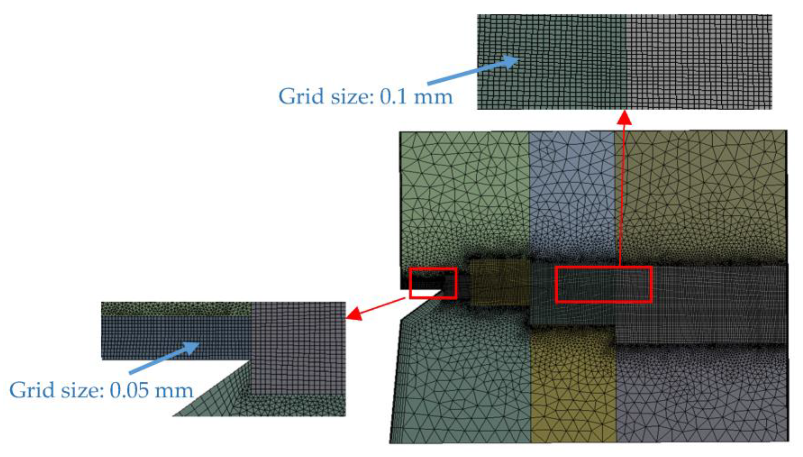
2.1. Model Assumptions and Computation Domain

The three-dimensional unsteady-state CFD model developed in this research for simulating centrifugal granulation of molten slag using a spinning cup is based on the following general assumptions:
(1) The slag film thickness is stable at the edge of the spinning cup and has a fixed radial mass flowrate and uniform temperature;
(2) The cross section of the film at the edge of the spinning cup is defined as an inlet to the computation domain;
(3) In the vicinity of the spinning cup, the air flow is influenced only by the spinning cup and the slag motion;
(4) In order to keep the computation cost within a feasible limit without loss of representativeness, the computation domain includes only a limited but sufficiently large spatial region outside the sidewall of the spinning cup (i.e., the region where the slag film deforms into liquid ligaments, which then break into droplets);
(5) For the sake of limiting the computation cost, the solid sidewall of the spinning cup is neglected, thus the computation domain extends to the inner face of the sidewall, which is taken as a rotating solid wall boundary;
(6) Heat transfer and solidification of the slag due to cooling are neglected, but the formation of a thin layer of solid slag tip at the spinning cup edge is considered;
(7) The flow possesses rotational periodic symmetry about the axis of the spinning cup.
In the present modeling work, the slag inlet conditions (including slag film thickness and slag flowrate) were calculated using the two-dimensional (2D) CFD model previously developed for simulating the spreading process of molten blast furnace slag on the inner wall of the spinning cup [19]. Figure 1 schematically illustrates the computation domain of the two-dimensional CFD model established previously and that of the three-dimensional (3D) model developed presently, as well as how the former model simulation results (i.e., slag film thickness at the spinning cup edge) are introduced into the latter model.
Figure 2 gives a three-dimensional illustration of the computation domain together with types of boundary conditions defined in the present three-dimensional CFD model for simulating slag film breakup into droplets. In this model, all wall faces (e.g., the inner face of the spinning cup sidewall and the upper and lower faces of the solidified slag tip) were rotated along the θ direction by 10°, where no-slip boundary conditions were imposed. The rest of the faces were set as pressure outlets, where air can enter or leave the computation domain through these boundaries and slag droplets can leave the computation domain through the boundary numbered as 3. The normal gradients of the variables were set to 0 at these pressure outlets. In the θ direction, the boundary planes of the computation domain were set as rotational periodic conditions. The physical properties of the molten blast furnace slag and air used in the present CFD model are given in Table 1.
Figure 3 is a two-dimensional representation of the computation mesh generated using the meshing tool of ANSYS Workbench platform [21] for the present three-dimensional CFD model. This figure shows the grid divisions on the central vertical plane in the radial direction of the computation domain. The three-dimensional computation mesh is comprised of approximately 1.3 million grids. The region in which the slag ligaments and droplets are formed employs a structured mesh with grid sizes ranging from 0.05 mm to 0.1 mm, whereas the rest of the regions use unstructured meshes with a maximum grid size of 1 mm.

2.2. Governing Equations and Computation Scheme

According to the aforementioned general assumptions, the flow behavior of slag and air in question can be considered as three-dimensional unsteady-state two-phase turbulent flows with free surfaces that can be governed by the partial differential equations described in the volume of fluid (VOF) model [22] and SST k-ω turbulence model [23], which read as follows:
(1) Continuity equation:
ρ t + · ρ u = 0
(2) Momentum transport equations:
ρ u t + · ρ u u = p + · [ μ + μ t u + u ) T + F g + F s
(3) SST turbulence equations:
ρ k t + · ρ u k = · [ ( μ + μ t σ k 3 ) k ] + P k β ρ k ω
ρ ω t + · ρ u ω = · [ ( μ + μ t σ ω 3 ) ω ] + 1 F 1 2 ρ k ω σ ω 2 ω + α 3 ω k P k β 3 ρ ω 2
(4) Volume fraction equations:
r α t + · r α u α = 0
α = 1 N p r α = 1
where ρ is the density (kg·m−3); u is the velocity vector (m·s−1); p is the pressure (Pa); μ is the dynamic viscosity (Pa·s); μt is the turbulent viscosity (Pa·s); Fg is the source term due to gravity (N·m−3); Fs is the source term due to surface tension force (N·m−3), which is calculated using the continuum surface force (CSF) method of Brackbill et al. [24]; k is the turbulence kinetic energy (m2·s−2); ω is the turbulence eddy frequency (s−1); σk3 is the Prandtl number for turbulence kinetic energy; σω2 is the Prandtl number for turbulence eddy frequency in the transformed k-ε turbulence model; σω3 is the Prandtl number for turbulence eddy frequency; Pk is the turbulent kinetic energy generation rate (W·m−3); Np is the number of fluid phases; F1 is the mixing function; α3, β′, and β3 are the turbulence model constants; r is the volume fraction; and subscripts α and β are the fluid phase identification indices.
The above-mentioned governing equations were numerically solved using ANSYS CFX in this research. Based on the volume balance and integration of liquid volume fraction along the droplets’ radius, the contour surface of the liquid volume fraction of 0.4 was adopted in post-processing of the CFD simulation data to obtain the shape and size of the droplets generated.
In the present work, the computation schemes are comprised of four operation cases with different cup spinning speeds, as listed in Table 2. First, for each case, the previously developed two-dimensional CFD model was implemented to predict the slag film thickness at the cup edge [19]. Then, using the two-dimensional-model-predicted slag film thickness as an inlet condition, the presently developed three-dimensional CFD model was executed to simulate the breakup process of the slag film when leaving the cup edge driven by the centrifugal force.

3. Results and Discussion

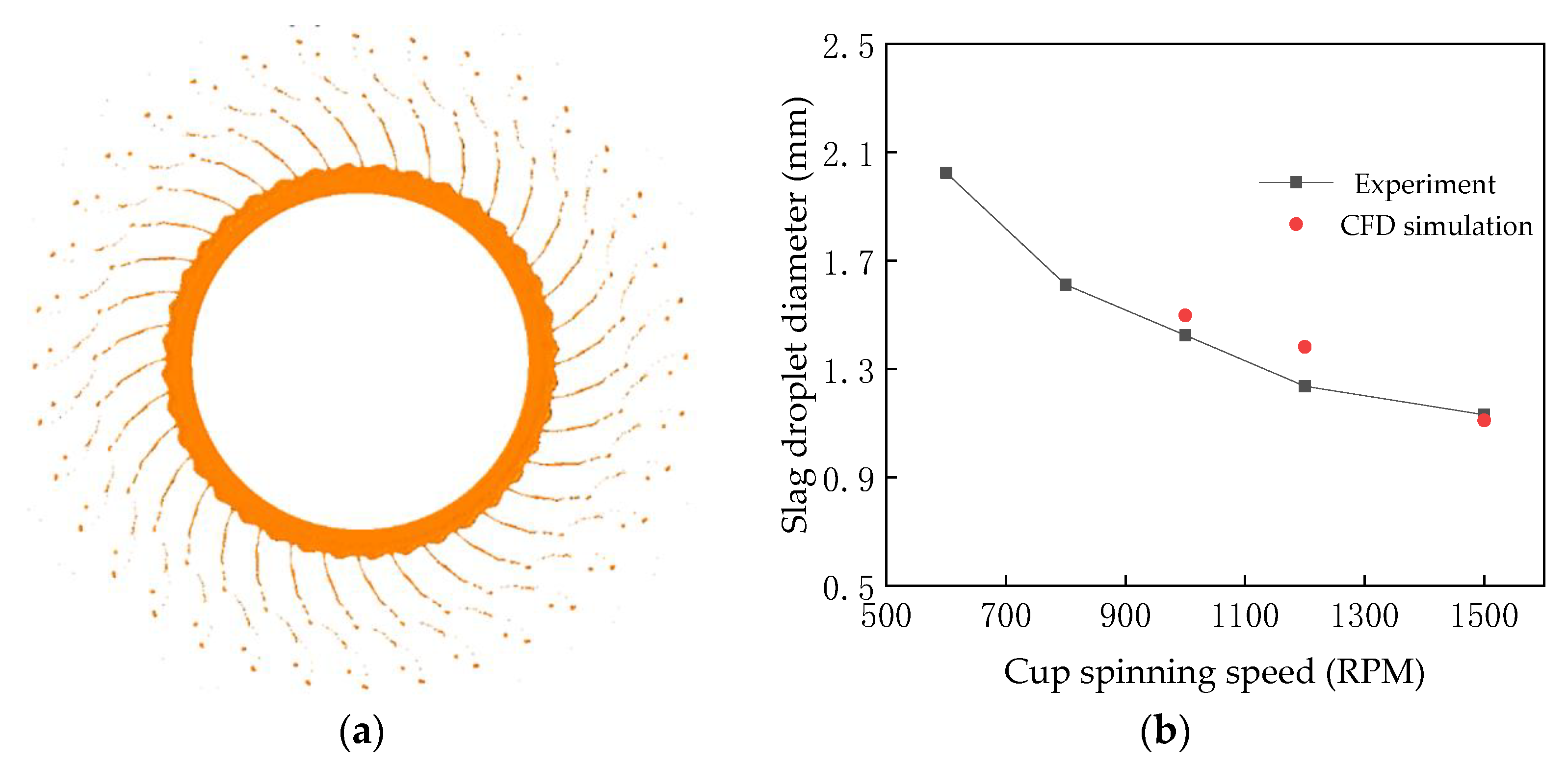
3.1. CFD Model Validity

In order to validate the three-dimensional CFD model developed in the present work, an experimental case reported by Liu et al. [25] was first simulated using the present model under the operation conditions described in Table 2. In this case, the measured diameters of the slag particles produced by centrifugal granulation of molten blast furnace slag with a spinning cup are available for comparison to the CFD model predictions. Figure 4 displays a time point at which the liquid slag film breaks into droplets and a comparison between the droplet diameters predicted by the CFD model and those experimentally measured for different cup spinning speeds. As seen from Figure 4a, the CFD model simulation generally reveals the slag granulation phenomenon observed in the experiment [25]. After leaving the spinning cup, the liquid slag film first deforms into curved ligaments that, at a specific distance away from the edge of the spinning cup, break into slag droplets, which eventually become solid particles after cooling down to room temperature. Owing to the action of inertial and surface tension forces, the necking phenomenon occurs at the end of the ligament, which eventually breaks to form large droplets (defined as primary breakup in this study), and then the remaining ligament between the large droplets breaks into a number of smaller droplets (defined as secondary breakup in this study). This process is similar to the annular spinning jet breakup process [26].
According to Figure 4b, under the same operation conditions given in Table 2, the average droplet diameter predicted by the present CFD model is generally close to those measured for the cup spinning speed in the range between 1000 RPM and 1500 RPM, and both follow the same trend with the variation of the cup spinning speed. Therefore, it can be considered that the three-dimensional CFD model established in the present work is generally valid for simulating the molten slag breakup process in ligament disintegration mode during centrifugal granulation with a spinning cup.

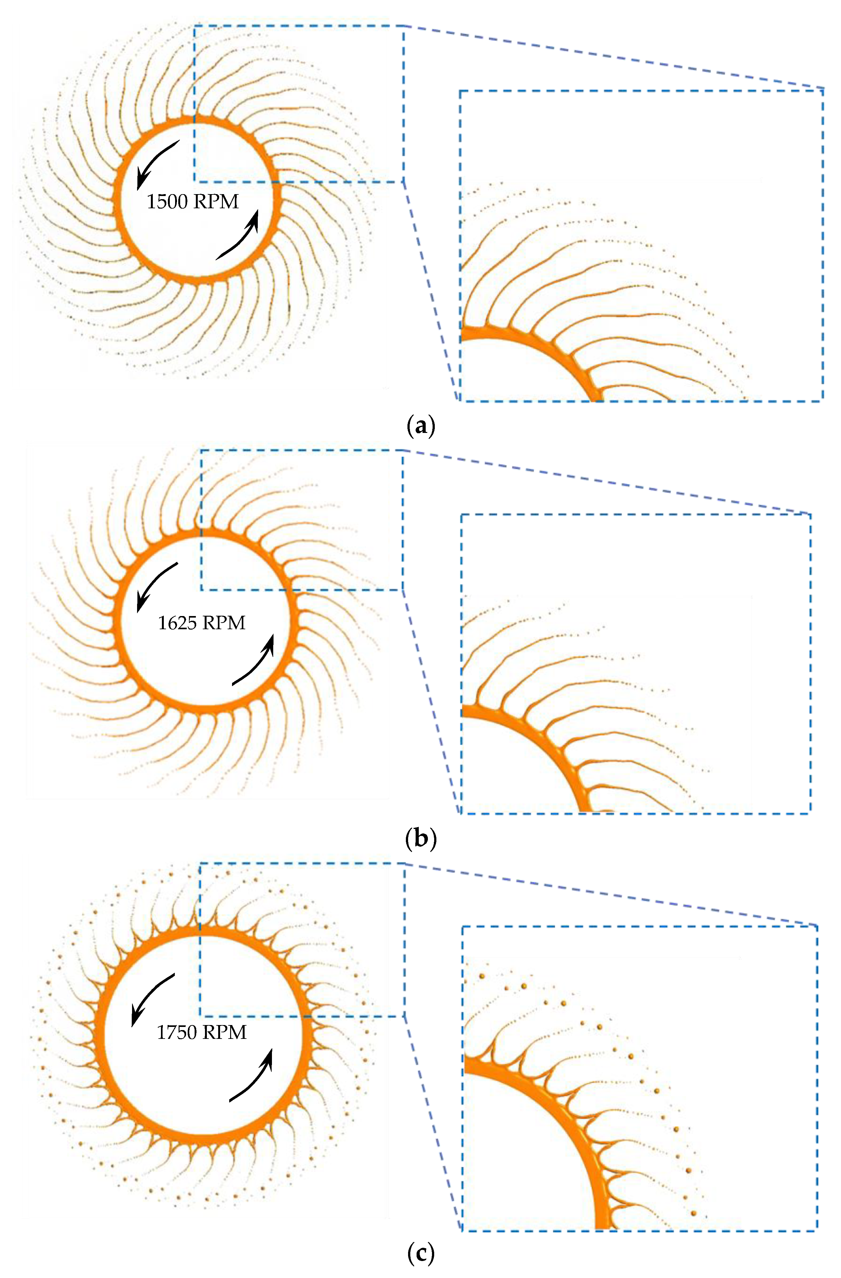
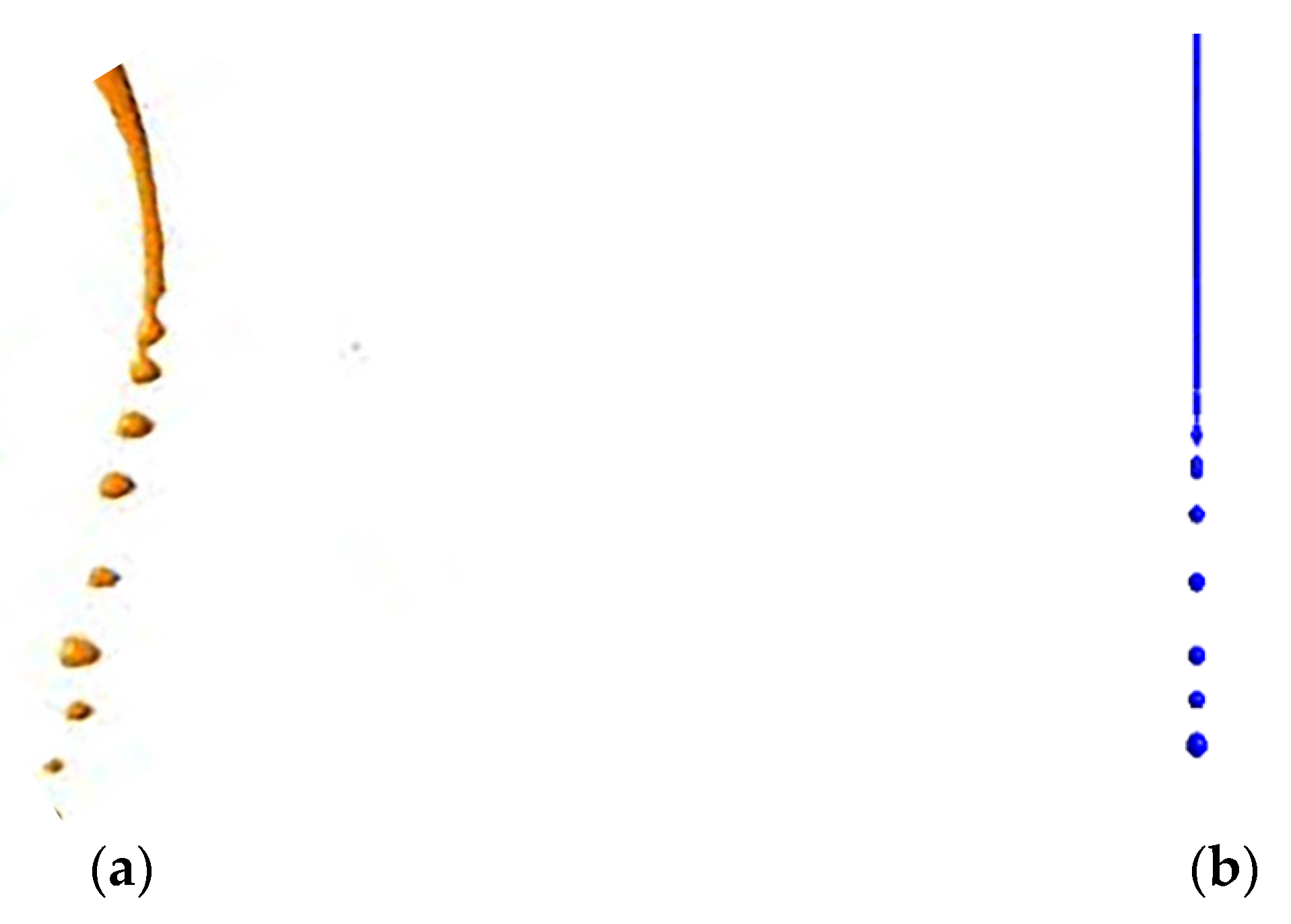
3.2. Breakup of Molten Slag Ligament in the Spinning Cup Centrifugal Granulation Process

Figure 5 depicts the CFD model simulated process of the breakup of a molten slag ligament into droplets, which is selected from the simulation result on centrifugal granulation of molten slag with a spinning disc at a time point of 0.072 s. The measurement position of the ligament diameter (dl) is marked in the figure as well. The operation conditions for this simulation case are a slag flowrate of 3 kg min−1 and cup spinning speed of 1750 RPM. It can be seen from this figure that the CFD model reveals that, while leaving the spinning cup, the liquid slag film breaks into droplets in ligament disintegration mode, driven by the centrifugal force. Focusing on one of the ligaments formed around the cup circumference, as shown by the enlargement of the ligament in Figure 5, the ligament is continuously stretched thinner when centrifugal force dominates over the surface tension force. When the centrifugal force tends to weaken owing to viscous friction inside the ligament itself and the resistance of the surrounding air, the surface force becomes dominant, driving the liquid slag to flow to the tip of the ligament. By then, the diameter of some sections of the ligament is periodically reduced by the impact of surface disturbance waves, creating a sequence of “necks”. Finally, as the ligament is stretched to its maximum length to become sufficiently thin and the surface disturbance waves amplify to a certain extent, the surface tension force eventually leads to the breakup of ligament necks, forming a string of droplets.

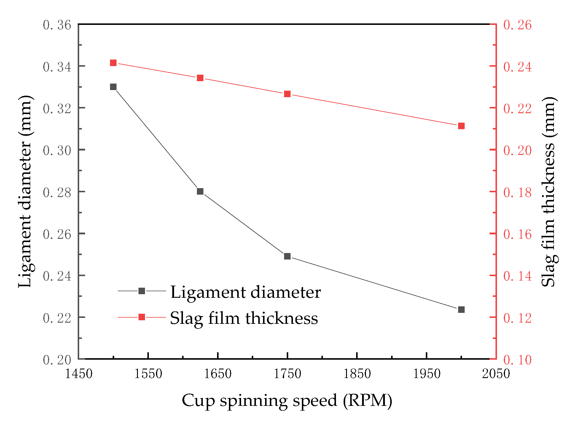
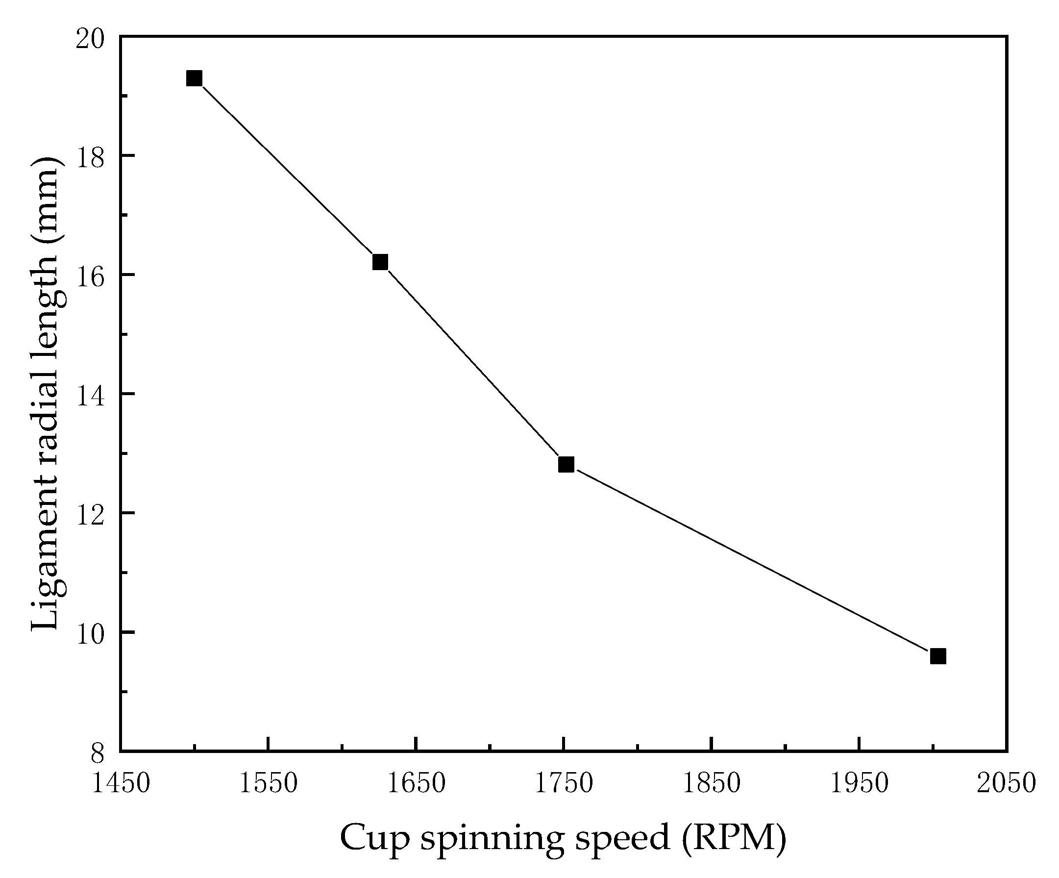
3.3. Effect of Cup Spinning Speed on the Granulation Process

In the entire process of centrifugal granulation of molten slag using a spinning cup, one of the most important and easily adjustable operating parameters is the cup spinning speed. Numerous research works have demonstrated that increasing the cup spinning speed is helpful for obtaining smaller-sized slag droplets. To study how the spinning speed affects the diameter of the slag ligament and the diameter of the droplets, as well as the correlation between the ligament diameter and the droplet diameter, CFD simulations were carried out with the cup spinning speed set at 1500 RPM, 1625 RPM, 1750 RPM, and 2000 RPM for the same slag flowrate of 3 kg min−1 (c.f., Table 2). Figure 6 illustrates the simulation results showing the breakup process of molten slag driven by a spinning cup operated under the above-mentioned conditions. It can be seen from local enlargements of this figure that the CFD simulation results do reveal that the slag is granulated in ligament disintegration mode for all cup spinning speeds and, as the cup spinning speed rises, the number of liquid ligaments around the cup periphery increases, and the ligament diameter and droplet diameter all decrease.
(1) Effect of cup spinning speed on molten slag ligament diameter
Figure 7 shows the effect of the cup spinning speed on molten slag film thickness at the cup edge and the diameter of the molten slag ligament. As seen from this figure, as the cup spinning speed increases, both the slag film thickness and the diameter of the slag ligaments decrease. This is because, when the cup spinning speed rises, the centrifugal force increases, leading to a thinner slag film at the cup edge, which accordingly produces thinner slag ligaments.
(2) Effect of cup spinning speed on molten slag droplet diameter
An essential consideration of the granulation effect is the size of the slag droplets (or solidified slag particles after cooling). Figure 8 shows the influence of the cup spinning speed on the average diameter of the slag droplets. It can be seen from this figure that the average droplet size reduces monotonically as the cup spinning speed increases. This is because, when the cup spinning speed increases, the slag film thickness decreases, producing thinner ligaments that eventually break into smaller droplets. Nevertheless, when the cup spinning speed is high enough (e.g., >1750 RPM), its effect on the droplet size becomes limited. This variation characteristic is consistent with that of the ligament diameter at high cup spinning speeds. Figure 7 indicates that, when the cup spinning speed increases from 1500 RPM to 1750 RPM, the average droplet diameter decreases from 0.6 mm to 0.448 mm (or by about 25%); however, a further increase in the cup spinning from 1750 RPM to 2000 RPM only results in a decrease in the droplet diameter from 0.448 mm to 0.414 mm (or by about 7.5%). Therefore, the present CFD simulation results demonstrate that the ligament diameter and droplet diameter all exhibit the same variation characteristics with the variation in the cup spinning speed.
(3) Effect of cup spinning speed on radial length of slag ligament
As seen from Figure 6, under the influence of the centrifugal force, the molten slag ligaments are curved, such that it is hard to accurately determine the ligament length. Instead, in order to examine the effect of the cup spinning speed on the ligament length, a radial distance between the spinning cup edge and the position at which the ligament starts to break into droplets (i.e., the end of the ligament) is defined in the present work, as shown in Figure 9. This radial distance is proportional to the ligament length, so it reflects the ligament length, and thus is termed the ligament radial length. Figure 10 depicts how the ligament radial length is influenced by the cup spinning speed. As the cup spinning speed increases, the ligament radial length decreases. This is because a higher cup spinning speed leads to a decreased slag film thickness at the cup edge, producing thinner ligaments, an increased slag flow velocity in each ligament, a larger frequency of “neck” appearance on the ligament, and thus an earlier start of breakup of the ligament at a shorter radial distance, all of which result in a shorter ligament length.

3.4. Mechanism of Molten Slag Ligament Breakup in the Spinning Cup Centrifugal Granulation Process

As an example, a molten slag ligament formed by a spinning cup with a cup spinning speed of 1750 RPM is selected from the CFD simulation results (Figure 6c) to compare its breakup process to the breakup process of a water ligament under gravity previously simulated by a CFD model [27]. The comparison result is shown in Figure 11. It can be seen from this figure that the breakup process of a molten slag ligament in centrifugal granulation using a spinning cup looks very similar to that of a water ligament under gravity. It is well known that, in the latter case, the mechanism of a water ligament breakup into droplets closely follows the law of the Rayleigh disintegration mechanism. Therefore, it may be inferred that the mechanism of breakup of a molten slag ligament into droplets driven by the centrifugal force should also approximately obey the Rayleigh disintegration mechanism. Both breakup processes exhibit the development of disturbance waves on the surface of the ligaments and the propagation and amplification of the waves cause a series of “necking” in the ligaments that eventually leads to the disintegration of the ligaments at the “necks”, forming a string of droplets.
To further demonstrate the similarity between the process of molten slag ligament breakup driven by centrifugal force and that of water ligament breakup under gravity, as well as the theory of the Rayleigh disintegration mechanism, the slag ligament and droplet diameters predicted using the present CFD model, as well as the water and liquid paraffin ligament and droplet diameters measured from low-temperature physical model experiments [27], are summarized in Table 3. This table also includes the ratios between droplet diameter and ligament diameter to compare to the theoretical ratio derived from the Rayleigh disintegration mechanism (i.e., Equation (3)).
In can be seen from Table 3 that the average ratio of slag droplet diameter to its ligament diameter is 1.84, while the ratios for water and liquid paraffin ligaments’ breakup measured from the physical model experiments are 1.90 and 1.86, respectively, all of which are very close to the theoretical ratio of 1.89 given by the Rayleigh disintegration mechanism. The similarity in the mode of ligament breakup into droplets among different types of liquids lies in the fact that, when the liquid ligament is stretched to a certain small diameter, the unstable surface tension force breaks the liquid ligament. This process is mainly governed by the Rayleigh disintegration mechanism and thus approximately follows Equation (3) quantitatively. The reason why smaller droplets can be produced at higher cup spinning speeds is actually because of the production of thinner ligaments. Then, by approximately following the Rayleigh disintegration mechanism, the ligament breaks into nearly identical sized droplets, which is irrelevant to the type of liquid according to Equation (3). As centrifugal atomization of liquids using spinning cups and disks can produce ligaments with nearly identical diameters around the periphery of the cup or disk, the great advantage of this granulation technology in producing more uniform droplets and granules than the other atomization technologies (e.g., gas blasting and spraying) can now be explained using the theory of the Rayleigh disintegration mechanism. Therefore, the above analysis demonstrates that the Rayleigh disintegration mechanism can be used to approximately describe the mechanisms of ligament mode breakup in both centrifugal granulation of molten slag with a spinning cup and water and liquid paraffin breakup under gravity. Therefore, we can use the theory of Rayleigh disintegration mechanism to guide the design and operation of centrifugal granulation of molten slag using a spinning cup for industrial applications.

4. Conclusions

In the present work, a three-dimensional unsteady-state CFD model of centrifugal granulation of molten blast furnace slag using a spinning cup was developed and implemented to simulate molten slag breakup into droplets in ligament disintegration mode. The simulation results are compared to the breakup processes of a water ligament and a liquid paraffin ligament under gravity as well as the theoretical law of the Rayleigh disintegration mechanism. The following conclusions can be drawn from this work:
(1) For the same flowrate of molten slag, an increase in the cup spinning speed reduces the slag film thickness at the cup edge, increases the number of ligaments, decreases the ligament diameter and length, and subsequently decreases the diameter of the slag droplets.
(2) The main reason for using higher cup spinning speeds to produce smaller droplets is the generation of thinner ligaments that break into droplets whose diameter is intrinsically related to the ligament diameter through the law of the Rayleigh disintegration mechanism.
(3) A qualitative comparison in the breakup process of molten slag ligament driven by centrifugal force and that of a water ligament under gravity indicates that the two processes in ligament disintegration mode have similar characteristics, and both approximately follow the law of the Rayleigh disintegration mechanism.
(4) Quantitative comparisons in the ratios between droplet diameter and ligament diameter for centrifugal granulation of molten slag (1.84) and for breakup of water and liquid paraffin ligaments under gravity (1.86 and 1.90, respectively), as well as the theoretical ratio (1.89) derived from the Rayleigh disintegration mechanism, further demonstrate that the breakup processes all approximately follow the Rayleigh disintegration mechanism. Therefore, the law of the Rayleigh disintegration mechanism can be applied to guide the design and operation of centrifugal granulation of molten slag using a spinning cup.

Author Contributions

Conceptualization, A.Z. and Y.P.; data curation, A.Z. and M.Z.; formal analysis, A.Z., Y.P. and M.Z.; investigation, A.Z., Y.P. and S.Z.; methodology, A.Z. and S.Z.; resources, P.M. and X.F.; supervision, Y.P.; validation, A.Z. and M.Z.; visualization, A.Z. and S.Z.; writing—original draft preparation, A.Z., M.Z. and S.Z.; writing—review and editing, Y.P. and P.M. All authors have read and agreed to the published version of the manuscript.

Funding

This research received no external funding.

Data Availability Statement

Not applicable.

Acknowledgments

The authors would like to thank University of Science and Technology Liaoning for financial support for the present research work.

Conflicts of Interest

The authors declare no conflict of interest.

References

  1. Chen, Y.; Feng, J.; Xie, Z.; Zhu, Y. Exergy analysis and system optimization design of sensible heat recovery of blast furnace slag in fixed-bed. J. North China Electr. Power Univ. 2012, 39, 97–102. [Google Scholar]
  2. Liu, J.; Yu, Q.; Li, P. Cold experiments on ligament formation for blast furnace slag granulation. Appl. Therm. Eng. 2012, 40, 351–357. [Google Scholar] [CrossRef]
  3. Liu, J. Experimental study on heat transfer characteristics of blast furnace slag waste heat recovery device. Master’s Thesis, Northeastern University, Shenyang, China, 2009. [Google Scholar]
  4. Liu, J.; Yu, Q.; Qin, Q. System for Recovering Waste Heat from High Temperature Molten Blast Furnace Slag; John Wiley & Sons Inc.: Hoboken, NJ, USA, 2011. [Google Scholar]
  5. Wu, J.; Tan, Y.; Li, P.; Wang, H.; Zhu, X.; Liao, Q. Centrifugal-Granulation-Assisted thermal energy recovery towards low-carbon blast furnace slag treatment: State of the art and future challenges. Appl. Energy 2022, 325, 119835. [Google Scholar] [CrossRef]
  6. Feng, Y.; Zhang, Z.; Gao, J.; Feng, G.P.; Qiu, L. Research status of centrifugal granulation, physical heat recovery and resource utilization of blast furnace slags. J. Anal. Appl. Pyrolysis 2021, 157, 105220. [Google Scholar] [CrossRef]
  7. Yu, P.; Wang, S. Current and future of dry centrifugal granulation process. Key Eng. Mater. 2016, 719, 92–97. [Google Scholar] [CrossRef]
  8. Dombrowski, N.; Lloyd, T. Atomisation of liquids by spinning cups. Chem. Eng. J. 1974, 8, 63–81. [Google Scholar] [CrossRef]
  9. Liu, J.; Yu, Q.; Guo, Q. Experimental investigation of liquid disintegration by rotary cups. Chem. Eng. Sci. 2012, 73, 44–50. [Google Scholar] [CrossRef]
  10. Wu, J.; Wang, H.; Zhu, X.; Liao, Q.; Li, K. Cold experiment of slag centrifugal granulation by rotary atomizer: Effect of atomizer configuration. Appl. Therm. Eng. 2017, 111, 1557–1564. [Google Scholar] [CrossRef]
  11. Mizuochi, T.; Akiyama, T.; Shimada, T.; Kasai, E.; Yagi, J. Feasibility of rotary cup atomizer for slag granulation. Isij Int. 2001, 41, 1423–1428. [Google Scholar] [CrossRef] [Green Version]
  12. Wegener, M.; Muhmood, L.; Sun, S.; Deev, A. The formation and breakup of molten oxide jets. Chem. Eng. Sci. 2014, 105, 143–154. [Google Scholar] [CrossRef]
  13. Purwanto, H.; Mizuochi, T.; Akiyama, T. Prediction of granulated slag properties produced from spinning disk atomizer by mathematical model. Mater. Trans. 2005, 46, 1324–1330. [Google Scholar] [CrossRef] [Green Version]
  14. Wang, D.; Ling, X.; Peng, H. Theoretical analysis of free-surface film flow on the rotary granulating disk in waste heat recovery process of molten slag. Appl. Therm. Eng. 2014, 63, 387–395. [Google Scholar] [CrossRef]
  15. Wang, D.; Ling, X.; Peng, H. Simulation of ligament mode breakup of molten slag by spinning disk in the dry granulation process. Appl. Therm. Eng. 2015, 84, 437–447. [Google Scholar] [CrossRef]
  16. Cheng, R.; Zhang, H.; Li, Y.; Fang, Q.; Wang, B. Effect of process parameters on dry centrifugal granulation of molten slag by a rotary disk atomizer. J. Iron Steel Res. Int. 2021, 28, 263–271. [Google Scholar] [CrossRef]
  17. Liu, Y. Study on Droplet solidification characteristics of blast furnace slag granulation. Master’s Thesis, North China University of Science and Technology, Qinhuangdao, China, 2019. [Google Scholar]
  18. Lord Rayleigh, F.R.S. On the instability of jets. Proc. Lond. Math. Soc. 1878, 10, 4–13. [Google Scholar] [CrossRef] [Green Version]
  19. Zhang, S.; Zhao, M.; Ma, P.; Pan, Y.; Meng, F. Numerical modeling of centrifugal granulation of molten blast furnace slag using spinning cups. Iron Steel 2020, 55, 127–133. [Google Scholar]
  20. Inaba, S.; Kimura, Y.; Shibata, H.; Ohta, H. Measurement of physical properties of slag formed around the raceway in the working blast furnace. ISIJ Int. 2004, 44, 2120–2126. [Google Scholar] [CrossRef] [Green Version]
  21. ANSYS Inc. ANSYS CFX User’s Manual, Release 18.0; ANSYS Inc.: Canonsburg, PA, USA, 2017. [Google Scholar]
  22. Hirt, C.; Nichols, B. Volume of Fluid (VOF) method for the dynamics of free boundaries. J. Comput. Phys. 1981, 39, 201–225. [Google Scholar] [CrossRef]
  23. Menter, F. Two-equation eddy-viscosity turbulence models for engineering applications. AIAA J. 1994, 32, 1598–1605. [Google Scholar] [CrossRef] [Green Version]
  24. Brackbill, J.; Kothe, D.; Zemach, C. A continuum method for modeling surface tension. J. Comput. Phys. 1992, 100, 335–354. [Google Scholar] [CrossRef]
  25. Liu, J.; Yu, Q.; Dou, C.; Hu, X. Experimental study on rotary cup granulation of blast furnace slag. In Proceedings of the National Energy and Thermal Engineering Annual Conference, Guiyang, China, 5 November 2008. [Google Scholar]
  26. Wang, G.; Ning, Z.; Lv, M.; Jiang, Z. Break process and surface wave of annular swirling viscous jet. Veh. Engine 2018, 5, 1–7. [Google Scholar]
  27. Zhao, M.; Pan, Y.; Zhao, A.; Zhang, S.; Ma, P.; Feng, X. CFD modeling and cold physical model simulation on single molten slag ligament disintegration into droplets. Miner. Spec. Issue Granulation Heat Recovery Metall. Slags 2023, 13, 139. [Google Scholar] [CrossRef]
Figure 1. Two-dimensional schematic illustration of computation domains defined in 2D and 3D CFD models.
Minerals 13 00316 g001
Figure 2. Three-dimensional illustration of the computation domain defined in the present CFD model for simulating slag film breakup into droplets. 1, 2, 3, and 4: pressure outlets; 5: slag inlet; 6: upper face of the solidified slag tip; 7: lower face of the solidified slag tip; 8: the solidified slag tip; 9: inner face of the spinning cup sidewall; 10: angle between the spinning cup sidewall and horizontal plane.
Minerals 13 00316 g002
Figure 3. Two-dimensional representation of grid division on the central vertical plane in the radial direction of the computation domain in the three-dimensional CFD model.
Minerals 13 00316 g003
Figure 4. Comparison of CFD simulation results with experimental measurements reported in the literature. (a) CFD model simulated breakup process of molten slag with a spinning cup. (b) Comparison of slag droplet diameter predicted by CFD model and those measured in experiment [25].
Minerals 13 00316 g004
Figure 5. Breakup process of a single molten slag ligament. 1: Enlargement of one ligament; 2: Measurement position of ligament diameter (dl); 3: Neck region of ligament.
Minerals 13 00316 g005
Figure 6. CFD simulation results on centrifugal granulation of molten slag at a flowrate of 3 kg min−1 and different cup spinning speeds. (a) Cup spinning speed = 1500 RPM; (b) Cup spinning speed = 1625 RPM; (c) Cup spinning speed = 1750 RPM; (d) Cup spinning speed = 2000 RPM.
Minerals 13 00316 g006aMinerals 13 00316 g006b
Figure 7. Effect of cup spinning speed on slag film thickness at the cup edge and slag ligament diameter.
Minerals 13 00316 g007
Figure 8. Effect of cup spinning speed on the average diameter of slag droplets.
Minerals 13 00316 g008
Figure 9. Definition of the radial distance between the spinning cup edge and end of molten slag ligament to the start of breakup.
Minerals 13 00316 g009
Figure 10. Effect of cup spinning speed on ligament radial length.
Minerals 13 00316 g010
Figure 11. Comparison of the CFD model predicted breakup process of a molten slag ligament under centrifugal force and that of a water ligament under gravity. (a) Molten slag ligament breakup; (b) Water ligament breakup.
Minerals 13 00316 g011
Table 1. Properties of liquid blast furnace slag and air used in the present CFD model [20,21].
MaterialDensity
(kg·m−3)
Dynamic Viscosity
(Pa·s)
Surface Tension
(N·m−1)
Liquid blast furnace slag25900.50.478
Air (at 25 °C)1.1851.831 × 10−5-
Table 2. Computation scheme for the present cases and literature case.
Simulation Case NumberCup Spinning Speed
(RPM)
Slag Film Thickness at the Cup Edge (mm)Other Conditions
1
2
3
4
15000.2415The slag flowrate is 3 kg min−1; the inner height of the cup wall is 5 mm; the inclination angle of the cup wall is 5°; and the diameter of the cup edge is 60 mm.
16250.2343
17500.2266
20000.2114
Literature case [25]10000.3440The slag flowrate is 6.667 kg min−1; the inner height of the cup wall is 20 mm; the inclination angle of the cup wall is 45°; and the diameter of the cup edge is 100 mm.
Table 3. Droplet diameter and ligament diameter as well as their ratio for different liquid ligaments’ breakup.
Study Method/
Liquid Ligament
Ligament Diameter
dl (mm)
Droplet Diameter
dp (mm)
dp/dl
0.220.411.85
CFD/Molten slag0.250.451.80
0.280.531.89
0.330.601.82
Average 1.84
0.451.132.51
0.601.252.08
0.851.601.88
Experiment/Liquid paraffin [27]1.001.731.73
1.252.051.64
1.452.251.55
Average 1.90
1.001.701.70
Experiment/Water [27]1.001.901.90
1.001.981.98
Average 1.86
Rayleigh disintegration mechanism (Equation (3)) [18]--1.89
Disclaimer/Publisher’s Note: The statements, opinions and data contained in all publications are solely those of the individual author(s) and contributor(s) and not of MDPI and/or the editor(s). MDPI and/or the editor(s) disclaim responsibility for any injury to people or property resulting from any ideas, methods, instructions or products referred to in the content.

