Article

Research on Engineering Practice and Effect Evaluation Method of Pressure Relief in Deep Rock Burst Danger Area of Coal Mine

1
School of Mining Engineering, Anhui University of Science and Technology, Huainan 232001, China
2
School of Mines, China University of Mining and Technology, Xuzhou 221116, China
3
Shandong Energy Group Luxi Mining Co., Ltd., Heze 274700, China
*
Author to whom correspondence should be addressed.
Minerals 2023, 13(4), 570; https://doi.org/10.3390/min13040570
Submission received: 5 March 2023 / Revised: 8 April 2023 / Accepted: 10 April 2023 / Published: 18 April 2023

Abstract

:
With a gradual increase in coal mining depth, the underground geological situation is more complex and the threat of rock bursts is more prominent due to the cross influence of multiple factors, such as faults, thick hard roofs, coal pillars, and high in situ stress areas. Additionally, it is difficult to test the effectiveness of multiple pressure relief measures after implementation in mining areas with rock burst dangers. By evaluating the geology and mining conditions of panel 5308 of the Tangkou coal mine, pressure relief prevention and control technology, combining pre-pressure relief and a danger relief measure, was proposed. An evaluation method for pressure relief implementation in deep mine rock burst danger areas was proposed, with changing rates of event frequency in microseismic high-energy intervals, changing rates of the mean values of hydraulic-powered support stress, and changing rates of bursting strain energy as evaluation indicators. The weight of each indicator was determined based on an analytic hierarchy process. The degree of pressure relief was measured by the pressure relief interval index. The comprehensive pressure relief effect index was calculated by an interval index and by a weight vector. Additionally, the classification standard of the pressure relief effect was proposed. The results show that the frequency of microseismic high-energy interval events decreased by 34.9%, the mean value of hydraulic-powered support stress decreased by 12.7%, and the bursting strain energy decreased by 14.7% after pressure relief was applied at panel 5308. Additionally, the interval indexes corresponding to each indicator were 3, 2, and 2 and the pressure relief effect index was 2.55, so the destress effect was good. The drilling method monitoring data show that the average value of the drilling powder decreased by 18% after pressure relief compared with before and the overall effect was good, which is consistent with the evaluation results of the multi-dimensional pressure relief implementation effect evaluation system, indicating that the evaluation system can accurately test the effectiveness of the multi-dimensional pressure relief implementation effect in deep mine rock burst danger areas. The results of the study provide methodological support and reference for the monitoring and prevention of rock bursts in mines with similar geological conditions.

1. Introduction

In recent years, most coal mines in China have entered deep mining, with some mines in the east-central part of the country having been mined to an average depth of over 1000 m. Additionally, they are still being extended at a rate of 10–25 m per year. Complex conditions at these depths have led to increasingly serious problems of rock bursts and other dynamic disasters and the precise prevention and control of rock bursts has become a worldwide problem. As of October 2021, China had 144 mines with rock bursts [1]; at the same time, China has been paying increased attention to domestic rock burst prevention and control problems.
At present, the research on the mechanism of rock bursts has resulted in relevant results and the mechanism of rock bursts induced by energy, strength, stiffness, “three factors”, and dynamic and static load superposition has been elaborated on and explained [1]. Many scholars have also conducted a lot of in-depth research on the technical problems of rock burst prevention and control [2,3,4]. In terms of the coal body pressure relief, Zhang et al. [5] used the classical mechanics theory to explain the mechanism of unloading pressure on coal bodies by large-diameter boreholes and they determined their reasonable parameters. Many other scholars have studied the influence of the size and strength of large-diameter boreholes regarding their mechanism of action through theoretical analysis, laboratory tests, and numerical simulations [6,7,8,9,10]. Xu [11] and Li [12] studied the parameters related to the weakening of coal seam water injection, as well as fracture development trends, through numerical simulations and other means. Chu et al. [13] studied the distribution of parameters, such as porosity and moisture, under different water pressures. They also studied the calculation method of coal seam water injection pressure under the influence of fracture by means of numerical simulation and experiments based on rock blasting theory. Based on this, they obtained a mechanism for evaluating blasting damage in different areas. Brigida et al. [14] studied the dependency of a shot hole number, the distance between shot hole axes and the borehole, and the proposed use of shot hole discharge to protect the shank of the vent hole from high rock pressure. Bosikov et al. [15] studied the efficiency of hydraulic fracturing technology in the process of oil and gas well construction and they determined, in practice, the ability of these wells to improve the efficiency of oil and gas field development. In terms of roof pressure relief, Zhao et al. [16] analyzed the influencing factors of front deep-hole roof blasting to reveal its mechanism of preventing and controlling rock bursts. They determined that the three-hole, fan-shaped, and gun-hole arrangements can effectively improve the anti-punching effect of deep-hole blasting of the roof and that the anti-punching and pressure relief effect increases with the increase in the gun-hole angle and charge length by numerical simulation. Huang et al. [17] systematically studied the typical morphology of a flat ellipsoid and the spatially steered extensional morphology of hydraulic fractures by true triaxial experiments. Based on this, they proposed a theoretical and complete technical framework for hydraulic fracture control in hard roofs. In terms of pressure relief effect evaluation methods, Wen et al. [18] used a combination of underground mine site and surface microseismic system monitoring to compare and analyze the pressure relief effects of two types of roof pressure relief blast holes; they obtained a better pressure relief effect, which possessed a tendency of forming fan arrangement schemes. Wu et al. [19] evaluated the pressure relief effect of tunnel pressure relief blasting using Russense’s rock burst discriminant method and they obtained better results. Kulikova [20] proposed a comprehensive risk assessment method based on complex indicators: “rock mass–technology–underground object–environment”. This method can be used to predict certain hazardous events that may occur during the mining process.
Many scholars have conducted a large amount of research and tests on pressure relief technology for deep rock burst mines. However, there is no unified index system for evaluating the effect of pressure relief after taking measures in mines in different areas. This is due to the large differences in geological factors and technical parameters of impact prevention engineering, which make the construction of impact prevention engineering blind, low in productivity, and unsafe with regard to the hazards of mining work. Therefore, a comprehensive quantitative evaluation of multiple indicators for the implementation effect of pressure relief in deep well impact hazard zones is an effective method to solve the above problems.
This paper addresses the problem that it is difficult to accurately determine the pressure relief effect in deep rock burst mines. Panel 5308 of the Tangkou coal mine in Shandong, China was taken as the engineering background, a pressure relief engineering practice was introduced, and the mechanism of pressure relief by a large-diameter drillhole and destress blasting was analyzed. By combining microseismic data analysis, hydraulic bracket stress data analysis, and bursting strain energy data analysis, a comprehensive quantitative multi-indicator evaluation method was constructed for the implementation effect of pressure relief in deep well impact hazard zones through the analytic hierarchy process (AHP), which provides quantitative measurement indexes for multi-dimensional pressure relief projects in coal mines and feeds back the implementation effects of pressure relief projects on site. The results can provide methodological support and reference for the monitoring and prevention of rock burst in mines with similar geological conditions.

2. Mechanism of On-Site Multi-Dimensional Pressure Relief Prevention and Control Technology

When a coal mine enters deep mining, the geological environment in the mine is more complex, with high in situ stress, thick and hard roofs, faults, folds, and other complex geological conditions appearing frequently. At the same time, due to the impact of mining at the panel, it is very easy to induce dynamic disasters during the mining period. At this time, the use of a single pressure relief method can no longer meet the production safety requirements of the working face. Multi-dimensional pressure relief prevention and control can be based on a variety of pressure relief measures for the complex geological conditions of working face mining in a rock burst danger area for zoning and graded prevention and control.
The multi-dimensional pressure relief prevention and control technology adopted at panel 5308 of the Tangkou coal mine is mainly divided into pre-pressure relief and danger relief measures. The rock burst pre-pressure relief prevention and control program of “first unloading pressure, then mining” has been adopted in the advance entry section, with burst risk during the mining period. The risk area of rock burst determined by monitoring and analysis in an advanced coal roadway can be relieved and unloaded by measures of a large-diameter drillhole and destress blasting in the coal seam.
On-site multi-dimensional pressure relief prevention and control technology is based on a combination of a large-diameter drillhole, roof blasting, and destress blasting measures in the coal seam.

2.1. Mechanism of Pressure Relief by Large-Diameter Drillhole in Coal Seam

By constructing a large-diameter drillhole in the coal seam, the stress concentration of the coal seam will be reduced to some extent. After constructing a large-diameter drillhole in a high-stress coal body, the fracture zone will be formed around the drillhole. Meanwhile, after constructing several large-diameter drillholes, their fracture zones can be enlarged and connected by controlling parameters, such as drillhole spacing and the drillhole diameter, so that the stress concentration in the coal body will be further reduced and the stress concentration zone will be shifted towards the deep part of the coal body, which will reduce the risk of dynamic disaster. The mechanism of pressure relief by a large-diameter drillhole in the coal seam [21,22] is shown in Figure 1. After implementing a large-diameter drillhole in the coal seam, the overall stress in the coal body decreases and the peak stress is directed away from the coal rib zone.
In the practice of rock burst prevention and control, the common large-diameter drillhole diameter range is 100 mm–200 mm. The inclination is usually parallel to the coal seam, the usual standard of drillhole depth is over the peak position of coal rib zone abutment pressure, and the specific requirements are as follows: when the coal seam mining thickness is less than 3.5 m, the drillhole depth is generally not less than 15 m; when the coal seam mining thickness is 3.5 m–8 m, the drillhole depth is generally not less than 20 m; when the thickness of the coal seam is more than 8 m, the drilling depth is not less than 25 m.

2.2. Mechanism of Pressure Relief by Roof Blasting and Destress Blasting in Coal Seam

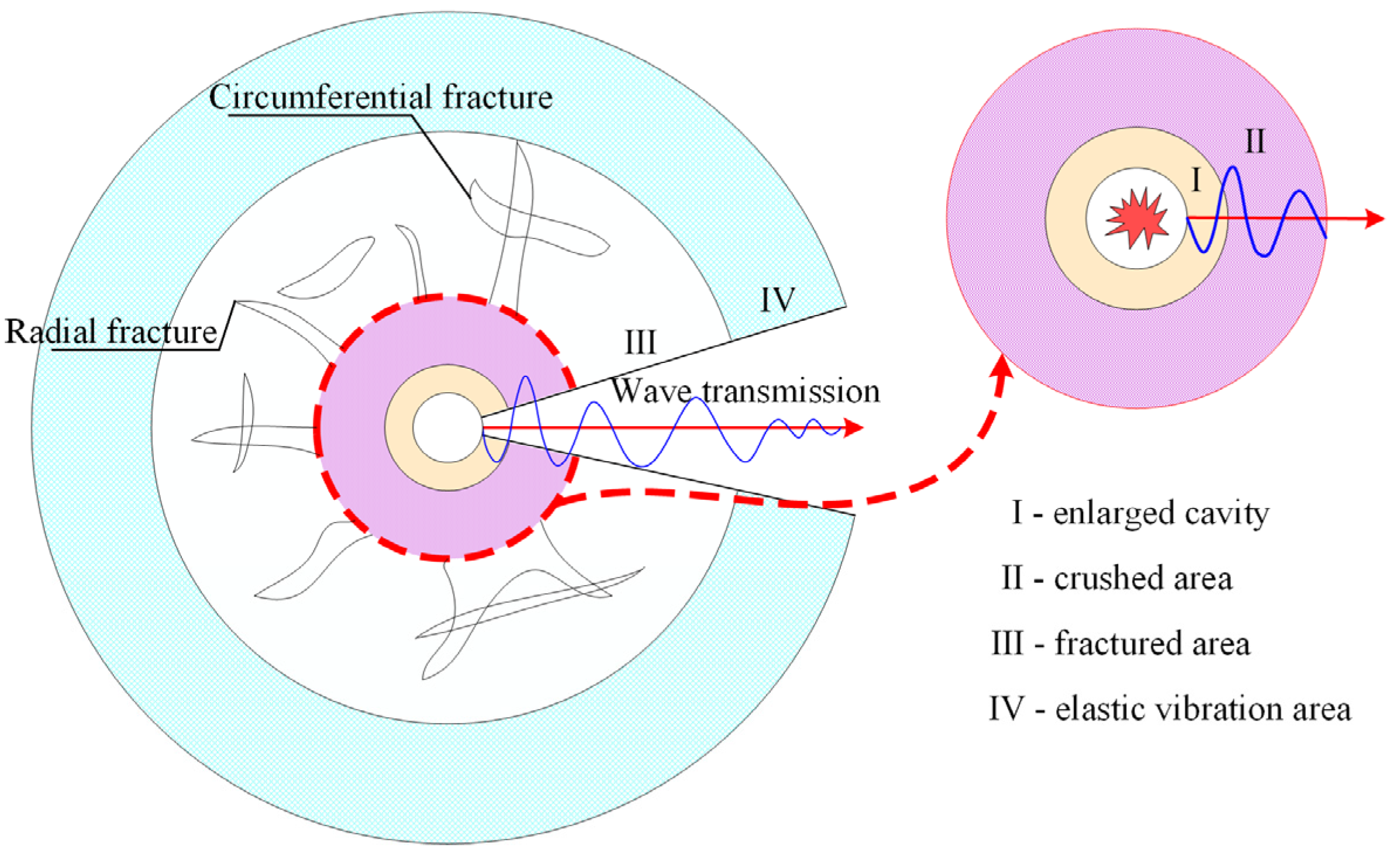
Roof blasting and destress blasting in a coal seam through the implementation of the roof rock or coal body drilling blasting causes blast damage to the coal rock media, which is accompanied by a complex dynamic evolution process. When the explosive in the hole explodes, the coal rock body suffers different damage in the radial direction, with the blast hole as the center; the blast hole’s enlarged cavity, crushed area, fractured area, and elastic vibration area will be formed around the blasting hole. The internal blast partition is shown in Figure 2.
A generated explosive dynamic load will instantly generate explosive gas. Near the blasting hole in a certain range, it will form an enlarged cavity and, with the impact of high-speed explosive gas, the blasting hole outside of the coal rock body will be subject to strong compression of the blasting shock wave damage and the formation of the crushed area. After the formation of this area, the explosion shock wave will decay and dissipate part of the energy in the form of stress waves that will continue to expand around the blasting hole propagation, causing radial compressive stress and tangential tensile stress around the coal rock media. When the tangential tensile stress is greater than the dynamic tensile strength of the coal rock media, it is pulled off, forming radial fractures. Explosive gas will wedge at a higher rate into the coal rock media fractures caused by secondary damage cracking of the coal rock, expanding the coal rock body’s primary and initial burst fractures. When the tangential stress is less than the dynamic tensile strength of the coal rock body, it will produce reverse tensile stress in the direction of the blasting hole. When the reverse tensile stress exceeds the dynamic tensile strength of the coal rock body, a circumferential fracture will be formed. The radial fracture, the circumferential fracture, and the original coal rock body in the primary fracture forms longitudinally and horizontally, forming a fractured area. Outside this area, the stress wave decays into a seismic wave. The seismic wave can only cause vibration of the mass without destroying the structure of the coal rock body; this area is the elastic vibration area [23].
Among the four divisions formed by destress blasting inside the coal rock body, the size of fractured area III directly affects the pressure relief effect [24]. The radius of the fractured area is calculated according to the principle of stress wave stretching action, as follows [25]:
r F = r c b σ d σ t 1 a ,
where rc is the radius of the explosive; b = ν/(1 − ν); ν is the Poisson’s ratio of the coal body; a is the stress wave attenuation index, a = 2 − μ/(1 − μ); μ is the dynamic Poisson’s ratio of the coal body, which is related to the strain rate and is generally taken as 0.8 times the Poisson’s ratio ν; σt is the tensile strength of coal body; σd is the initial radial stress caused by the stress wave, which can be calculated as follows:
σ d = ρ 0 D 1 2 8 r c r b 6 n ,
where D1 is the explosion speed; ρ0 is the density of explosives; rb is the radius of the blast hole; n is the pressure increase factor, 8 < n < 11.
According to the relevant research [26], the radius of these four divisions is proportional to the radius of the explosives, as shown in Table 1.
After blasting in the roof or coal seam, the crushed area and fractured area formed therein will destroy the integrity of the coal rock body so that it does not have the ability to accumulate a large amount of elastic energy, thus reducing the strength of the dynamic load induced when the roof rock breaks and falls and reducing the degree of energy accumulation in the coal body. On the other hand, taking measures of roof blasting and destress blasting in the coal seam can accelerate the attenuation of the mine earthquake load, thus weakening the impact of the mine earthquake load on the working face.
On-site multi-dimensional pressure relief prevention and control technology is used for deep mining rock burst danger areas from two aspects: pre-pressure relief and danger relief. Large-diameter drillholes are used for both of them. Roof blasting is often used for pre-pressure relief at the working face and destress blasting in the coal seam is used for danger relief when large-diameter drillholes cannot be effective.

3. Engineering Background and Practice of Pressure Relief in Deep Rock Burst Danger Areas of Coal Mine

3.1. Engineering Background

3.1.1. Engineering Geological Conditions

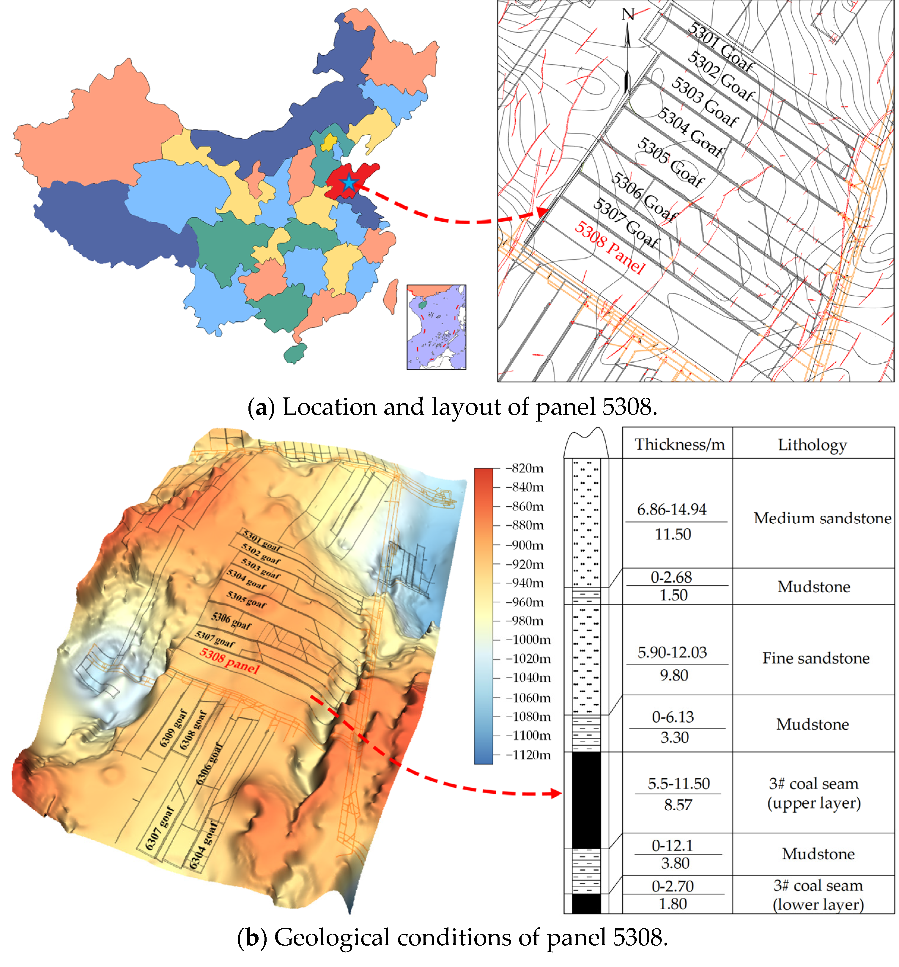
The Tangkou coal mine is in Jining, Shandong, China. The main coal-bearing strata in the well field are the Shanxi and Taiyuan formations of the Carboniferous to the Permian Yuemengou Group. Panel 5308 is located in the 530 district of the Tangkou coal mine. The northeast side of the panel is the 5307 goaf, with a 5 m small coal pillar remaining in the middle. The 630 main roadway is about 220 m to the southwest and the unexplored solid carbon area is to the west. All coal seams above and below the vertical are not mined and there is no goaf. The burial depth of panel 5308 is about 921–991 m, the length is 1639 m, and the width is 190 m. The geological conditions around panel 5308 are complicated and four faults have been revealed in the process of shaft and drift development. Among these faults, the F5308-2 fault was revealed by the head entry, which has a 90° angle with the direction of the workface pushing and a large impact on the mining process. The coal seam thickness is about 5.5–11.5 m, with an average thickness of about 8.57 m, and the coal seam inclination angle is 0–14°, with an average of 4°. The location, layout, and geological conditions of panel 5308 are shown in Figure 3.
The immediate roof of panel 5308 is gray-black mudstone, with an average thickness of 3.30 m, containing a lot of plant fossils and pyrite fine crystal film. The main roof is fine gray-white sandstone, with an average thickness of 9.80 m, composed of mainly quartz, followed by feldspar. It has clayey pore-type cementation, medium sorting, and sub-rounded, parallel, and wavy laminations. The immediate floor is gray-black mudstone, with an average thickness of 3.80 m, containing plant roots and fossils, with jagged fractures. The main floor is fine light-gray sandstone, with an average thickness of 11.50 m, composed of quartz, feldspar, and dark minerals. The strength parameters of the country rock and coal in panel 5308 are shown in Table 2.

3.1.2. Comprehensive Evaluation of Geological Conditions

  • Geological structure.
The geological structure index classification of panel 5308 is shown in Table 3.
Panel 5308 is influenced by faults and other geological structures and the effect of tectonic stress can significantly reduce the critical mining depth of rock bursts. Panel 5308 is expected to reveal four faults during the mining process, including one with a fault throw greater than 20 m and three with fault throws greater than 5 m, and it is influenced by a fault across the panel. Based on the results of an in situ stress test around the 530 district, the direction of the maximum tectonic stress obtained was 116.73–137.77°, the maximum tectonic stress was 39.41 MPa, the minimum was 22.69 MPa, and the gravity stress was 25.32 MPa. The maximum tectonic stress was 1.56 times the gravity stress, which had an obvious influence on the deformation and damage of the underground rock formation and the appearance of the mine pressure. The maximum tectonic stress was 1.74 times greater than the minimum tectonic stress and the influence of the tectonic stress on the roadway excavation had more obvious directionality. So, the geological structure of panel 5308 is level III and the tectonics are very developed, with strong rock burst danger.
2.
Coal rock structure.
The bending energy index refers to the bending energy accumulated by the cantilever rock beam of the unit width reaching the ultimate span under the action of the uniform load. According to the size of the UWQ, the coal rock structure can be divided into three levels [27], as shown in Table 4.
The formula for calculating the UWQ is as follows:
U WQ = 102.6 R t 5 2 h 2 q 1 2 E ,
where Rt is the tensile strength of the rock specimen; h is the thickness of the single roof plate; E is the elastic modulus of the rock specimen; q is the overburden load per unit width, which can be calculated as follows:
q = E 1 h 1 3 g ρ 1 h 1 + ρ 2 h 2 + L   + ρ n h n E 1 h 1 3 + E 2 h 2 3 + L   + E n h n 3 × 10 6 ,
where Ei (i = 1, 2, …, n) is the elastic modulus of the overlying strata; hi (i = 1, 2, …, n) is the thickness of the overlying strata; ρi (i = 1, 2, …, n) is the block density of the overlying strata.
The main roof of panel 5308 is hard fine sandstone, with an average thickness of 9.80 m, uniaxial compressive strength (UCS) of 50.248 MPa, and a measured roof bending energy index of UQW = 34.83 kJ, so the coal rock structure is graded as level II, with medium rock burst danger.
3.
Coal rock burst tendency
The degree of burst tendency of coal rocks is evaluated by four indexes related to the burst energy index KE, elastic energy index WET, dynamic damage time DT, and the uniaxial compressive strength RC of the coal rock. The coal rock burst tendency classification is shown in Table 5. Among them, the dynamic damage time DT is the time from the ultimate load to the complete loss of the load-bearing capacity of the coal sample under the uniaxial compression test, that is, the time required to release the energy completely. The shorter the dynamic damage time DT, the higher and faster the instantaneous release of elastic strain energy and the greater the propensity of the coal sample to burst during the damage.
The test results of the burst tendency of panel 5308 show that the dynamic damage time DT of the coal is 177 ms, the burst energy index KE is 4.33, the elastic energy index WET is 3.56, and the uniaxial compressive strength RC is 13.47 MPa. According to the comprehensive grading in Table 5, the coal rock burst tendency of the panel belongs to level II and has a medium burst tendency.

3.1.3. Rock Burst Danger Area Classification

Based on the geology and mining technology conditions of panel 5308, the rock burst danger area is divided into three classes, as shown in Figure 4.

3.2. Engineering Practice of On-Site Multi-Dimensional Pressure Relief

Panel 5308 revealed four faults in the process of excavation and the pressure of the destress measures during the mining process was very high. Mining of the panel began in September 2020; large-diameter drillhole and roof-blasting measures were used for pre-pressure relief and large-diameter drillhole and destress blasting measures in the coal seam were used for danger relief.
The parameters of the pre-pressure relief using a large-diameter drillhole in panel 5308 are shown in Table 6.
The roof blasting pressure relief project of panel 5308 started from a position 50 m away from the setup entry in both the head entry and tail entry. The blasting hole spacing in the strong rock burst danger area was 15 m and the spacing in the medium and weak areas was 20 m.
From the perspective of field engineering practice, the drilling depth, inclination, and explosive amount of roof blasting are related to the position of overlying hard roof strata on the working face. The purpose of roof blasting is to pre-split the overlying thick rock strata on the working face so that it cannot form a large cantilever area to cause pressure. Therefore, the drilling depth should go deep into the overlying thick and hard rock strata. There are two thick and hard sandstone layers on the roof of panel 5308. The depth of the blasting hole was determined to be 30 m and the elevation angle was 75 degrees, which penetrated the overlying two thick and hard sandstone layers. The diameter of the blasting hole was 75 mm, the charge length was 12 m, the sealing length was 18 m, and the quantity of explosive was 33.6 kg, using a three-stage emulsion explosive approved for the coal mine. Before mining and after excavating, roof blasting was used for blasting the 300 m area in front of the panel.
The measures of the large-diameter drillhole and roof blasting are shown in Figure 5.
The rock burst danger identified by monitoring and analysis in the advanced coal roadway during the mining period can be relieved by large-diameter drillhole and destress blasting measures in the coal seam. Generally, a large-diameter drillhole in the coal seam is used first and, when the drillhole cannot be constructed by the site’s geological conditions, coal seam destress blasting can be used, in the order of 15 m outside the rock burst danger area rock burst danger area 10–15 m on the other side of the area. The specific danger relief parameters are shown in Table 7.
When using destress blasting in the coal seam, each blasting hole should be positively charged, with no more than 5.0 kg of charge and 2–4 detonators. The hole should be sealed with blistering mud, with a depth of not less than one-third. If the rock burst danger is not eliminated after the construction of the pressure relief hole, the hole should be re-drilled in the middle of the original implementation hole for secondary danger relief until the danger is eliminated.
A summary of the multi-dimensional pressure relief works in panel 5308 is shown in Figure 6.

4. Evaluation Method of Pressure Relief Effect in Deep Coal Mine Rock Burst Danger Area

After the implementation of multi-dimensional pressure relief measures based on pre-pressure relief and danger relief, the rock burst danger of mining and the possibility of dynamic disaster will be reduced, but, at present, it is impossible to implement an accurate quantitative evaluation of multi-dimensional pressure relief effects. Based on microseismic monitoring, hydraulic-powered support stress, and bursting strain energy data during pressure relief, this chapter proposes a comprehensive evaluation method of multi-dimensional pressure relief implementation effects and constructs a comprehensive evaluation system of multi-dimensional pressure relief effects based on the AHP, aiming to quantitatively evaluate the effects of implementing multi-dimensional pressure relief measures in deep mine rock burst danger areas and to provide a basis for realizing safe and accurate pressure relief in these areas.
Microseismic monitoring data are obtained by monitoring with seismic sensors arranged near the panel of the coal mine, which can automatically pick up channel information, locate the seismic source on the mine map, and automatically calculate the microseismic energy. The hydraulic-powered support stress data are obtained through the hydraulic-powered support stress monitoring system at the coal mine site. Based on the fact that the square root of the energy released by each earthquake is proportional to the strain within the rock mass before this earthquake occurs [28,29], the bursting strain energy can be expressed as
ε E = i = 1 N E i ,
where N is the total number of mine earthquake events after the last macro rupture and Ei is the energy released by the mine earthquake after the last macro rupture.
The multi-dimensional pressure relief effect evaluation system is constructed based on the AHP. The evaluation indicators are the change rate of the event frequency in microseismic high-energy intervals, the change rate of the mean value of the hydraulic-powered support stress, and the change rate of the bursting strain energy.
  • Construction of comparative scales.
Three evaluation indicators are used in the evaluation system to construct a five-level evaluation scale, as shown in Table 8.
2.
Construction of judgment matrix.
Microseismic monitoring is able to obtain information on the vibration of the surrounding rock formations during the mining process at the panel, which is particularly important. The frequent occurrence of large energy events means that the rock formations around the panel are highly active and the risk of rock burst increases. What the hydraulic-powered support stress monitoring data can show is the stress level of the roof rock layer above the support, which can show the limited risk of rock burst and is second in importance. The bursting strain energy data are based on the microseismic monitoring data, which can reflect the concentration of deformation energy in the rock formation area around the panel for a period of time, showing that the risk of rock burst is more macroscopic and is the least important compared with the first two.
The aij in the judgment matrix is the result of a comparison between the importance of element i and element j. If element i is more important than element j, aij is taken as 3, and so on; the judgment matrix can be calculated and has the following properties:
a i j = 1 a j i ,
Based on the above analysis, the judgment matrix for pressure relief effects can be obtained as shown in Table 9.
3.
Consistency test.
By calculating the maximum eigenvalue of the above judgment matrix, we can obtain λmax = 3. According to the relationship between the judgment matrix and the eigenvectors,
QWmax = λmaxWmax,
where Q is the judgment matrix and Wmax is the eigenvector. The corresponding eigenvectors can be calculated as follows:
Wmax = [0.8571   0.4286  0.2857].
Regarding the consistency test on the eigenvector, if CR < 0.1, then the consistency test passes, indicating that the judgment result is consistent with or similar to the actual situation; otherwise, the relevant parameters need to be adjusted until the consistency test conditions are met. The consistency test is as follows:
C I = λ max n n 1 ,   C R = C I R I ,
where n is the order of the judgment matrix; CI is the consistency index; RI is the average random consistency index. The calculation method of RI is: randomly construct 500 judgment matrices A1, A2, …, A500. Then, the consistency index CI1, CI2, …, CI500 can be obtained and RI can be calculated as follows:
R I = C I 1 + C I 2 + L   + C I 500 500 = λ 1 + λ 2 + L   + λ 500 500 n n 1
The values of RI are shown in Table 10.
The consistency test was calculated at CR = 0 and passed.
4.
Determine the weight vector.
The eigenvectors that pass the consistency test are normalized to obtain the weight vectors for each indicator:
W = [0.55    0.27    0.18].
5.
Evaluation indicators’ interval index.
Each evaluation indicator can be derived from the corresponding interval index Di, according to Table 11.
6.
Comprehensive evaluation of pressure relief effect.
Based on the weight vector W and the interval index of each indicator, the final pressure relief effect index can be calculated as follows:
C = WiDi, i = 1, 2, 3,
where Wi is the weight of each indicator in the weight vector W and Di is the interval index of each indicator.
Based on the pressure relief effect classification in Table 12, the overall pressure relief effect of the working face can be derived.

5. Application of the Evaluation Method in Deep Rock Burst Danger Area of Coal Mine

By comparing the data of the microseismic monitoring, the hydraulic-powered support stress, and the bursting strain energy before and after destress, the pressure relief implementation effects of panel 5308 were evaluated. The panel was fully destressed by the end of October 2020 and was pushed to the high-stress area in March 2021. During these two periods, both ends of the working face were in strong rock burst danger areas. The data from October 2020 and March 2021 were taken for multi-dimensional pressure relief effect evaluation and analysis.

5.1. Pressure Relief Effect Evaluation of Microseismic Data

Microseismic data can well reflect the surrounding rock activity during the mining period. When using microseismic data to evaluate the pressure relief effect, factors such as the goaf around the panel, coal pillar, fault, and the influence range of the working face mining, etc., should be considered. Microseismic data within the above influence area should be selected to evaluate the pressure relief effect.
Panel 5308 is surrounded by the 5306 and 5307 goaves, while the tail entry is adjacent to a fault. The microseismic data from October 2020 and March 2021 were taken for evaluation, as shown in Figure 7. As can be seen in Figure 7, there were 611 microseismic events in October 2020, including 210 events with an energy of 102–103 J, accounting for 34.4%, and 401 events with an energy of 103–104 J, accounting for 65.6%. There were 660 microseismic events in March 2021, including 399 events with an energy of 102–103 J, accounting for 60.5%, and 261 events with an energy of 103–104 J, accounting for 39.5%. The frequency of microseismic events in the energy range of 103–104 J decreased by 34.9% after pressure relief, while those in the range of 102–103 J increased by 90%, mainly due to the increase in the small-amplitude disturbances brought about by the large-diameter drillhole and roof-blasting construction during the pressure relief. Overall, the frequency of microseismic events in the high-energy range decreased and the frequency of microseismic events in the low-energy range increased after the pressure relief. The interval index of this indicator is C1 = 3.

5.2. Pressure Relief Effect Evaluation of Hydraulic-Powered Support Stress Data

The evaluation of the pressure relief effects using hydraulic-powered support stress data should consider the influence of complex geological formations, such as side abutment pressure from surrounding goaves, a thick hard roof, faults, etc., during the mining period. To fully consider these influences, the hydraulic-powered support stress data near the above-mentioned influence area should be selected for the evaluation of pressure relief effect.
The changing pattern of the hydraulic-powered support stress monitoring data of panel 5308 during the mining period from September 2020 to September 2021 is shown in Figure 8.
As can be seen in Figure 8, the stress level of hydraulic-powered support at both ends of panel 5308 was higher in the area close to the entry and the middle of the working face. Panel 5308 was influenced by the side abutment pressure from the nearby 5306 and 5307 goaves during the mining period, while the tail entry was close to a fault. The following three groups of hydraulic-powered support were selected for evaluation: (1) 5#, 15#, 25#, and part of the supports around them near the 5308 head entry; (2) 40#, 50#, 60#, and part of the supports around them near the middle of the panel; (3) 80#, 90#, 100#, and part of the supports around them near the 5308 tail entry. The mean values of the stress of these hydraulic-powered supports in October 2020 and March 2021 are shown in Figure 9.
Based on the data in Figure 9, the following equations were obtained by fitting and modeling the mean stress for each hydraulic-powered support for October 2020 and March 2021:
S before = 0.0004 n 3 0.0397 n 2 + 1.1028 n + 19.377 ,
S after = 0.00009 n 3 0.0197 n 2 + 0.7212 n + 17.315 ,
where Sbefore is the hydraulic-powered support stress before destress, Safter is the support stress after destress, n is the hydraulic-powered support number, n = 1, 2, 3, …, N, and N is the total number of hydraulic-powered supports in the panel.
As can be seen in Figure 9, the mean stress value of the first group before the pressure relief reached 25.2 MPa; afterward, it was 21.6 MPa, showing a decrease of about 14.3%. The mean stress value of the second group before the pressure relief was 28.5 MPa; afterward it was 24.6 MPa, with a decrease of about 13.7%. The third group before was 25.4 MPa and 20.5 MPa after, with a decrease of about 19.3%. Due to the implementation of the roof blasting and the large-diameter drillhole, the mean stress value of the hydraulic-powered support at panel 5308 decreased. Taking the mean stress decrease rate of the second group for the pressure relief effect evaluation calculation, its decrease rate was 13.7%, so the interval index was C2 = 2.

5.3. Pressure Relief Effect Evaluation of Bursting Strain Energy

Using the change rate of the bursting strain energy in October 2020 and March 2021 for the pressure relief effect evaluation, combined with microseismic monitoring data, the bursting strain energy distribution of panel 5308 during the above two periods of mining is shown in Figure 10.
As can be seen in Figure 10, there were four energy concentration areas in October 2020 at panel 5308, mainly distributed in the coal rib zone and the tail entry in front of the working face, and one in March 2021 after the full implementation of the multi-dimensional pressure relief measures, distributed in the head entry in front of the working face. Although the peak of the bursting strain energy density increased from October 2020 to March 2021, combined with the microseismic monitoring results, the high-energy events decreased and the small-energy events increased and were more concentrated in March, which was mainly due to the partial disturbance brought by the construction of the pressure relief project. After the implementation of destress, the average bursting strain energy decreased by about 14.7% and its interval index was C3 = 2.

5.4. Evaluation Results of Pressure Relief Effect Based on AHP

The multi-dimensional pressure relief effect microseismic interval index was C1 = 3, the hydraulic-powered support stress was C2 = 2, and the bursting strain energy index was C3 = 2 for panel 5308. The pressure relief implementation effect index was calculated as
C = i = 1 3 W i D i = 2.55 ,
According to the pressure relief effect classification in Table 10, the multi-dimensional pressure relief effect of panel 5308 was good.

5.5. Validation of Multi-Dimensional Pressure Relief Effect Evaluation System

The drilling method is often used to predict rock bursts by constructing 42–50 mm diameter boreholes in the coal seam and identifying the risk of a rock burst based on the amount of excluded drilling powder and its changing pattern and related dynamic effects. The results of related studies have shown [30,31,32] that the amount of drilling powder increases with the increase in the country rock pressure; the two are positively correlated. When the discharge rate per unit length increases or exceeds the calibrated value, it indicates an increase in the stress concentration and an increase in rock burst risk. In this paper, the change in the amount of drilling powder when using the drilling method was used to verify the pressure relief effect, which could visually reflect the change in the degree of stress concentration at the site.
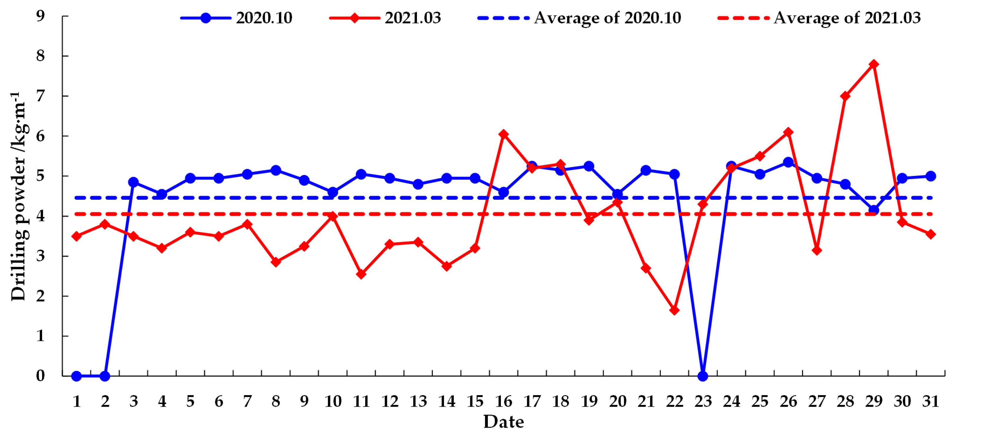
The monitoring results of the drilling powder at panel 5308 in October 2020 and March 2021 by the drilling method are shown in Figure 11. The monitoring location was 80 m away from the working face of the head entry, the drilling depth was 14 m, and the warning value was 10.83 kg/m. The data from 1, 2, and 23 October 2020 were not recorded due to the shutdown of the working face and the wetness of the drilling hole.
As can be seen in Figure 11, in October 2020, the drilling powder was basically between 4 and 5 kg/m, with an average value of 4.94 kg/m. In March 2021, the volume was between 3 and 4 kg/m, with an average value of 4.05 kg/m, which was about 18% lower than in October 2020. In March 2021, panel 5308 had been pushed to the strong rock burst danger area and was close to the F5308-3 fault. Under the influence of stress concentration on the fault and the “second square”, the drilling powder increased after March 16 and, although the peak increased to 6–8 kg/m, it still did not reach the warning value. The overall pressure relief effect was good, which was consistent with the evaluation results of the multi-dimensional pressure relief implementation effect evaluation system.

5.6. Plan for Further Prospective Study

The selection of the evaluation indexes in the pressure relief effect evaluation method proposed in this paper can be further studied. The data required for evaluation can also be obtained by stress online monitoring methods in addition to data obtained by the microseismic monitoring and the hydraulic-powered support stress monitoring methods, as well as other monitoring methods that may be used in coal mines. Secondly, the selection of the interval index indicators for evaluation data can be improved.

6. Conclusions

When coal mines enter deep mining, the rock burst danger area increases; however, the implementation of various pressure relief measures can prevent the occurrence of rock bursts. The work of this paper was based on the need for pressure relief effect evaluation of deep coal mine rock burst prevention and control. The multi-dimensional pressure relief effect evaluation system was established by using the AHP and applied in panel 5308 of the Tangkou coal mine in Shandong, China. Several main conclusions were drawn.
(1)
Based on the geological and mining technical conditions of panel 5308, the rock burst danger areas were divided. Multi-dimensional pressure relief prevention and control technology was proposed. Zoning and grading pre-pressure relief and danger relief measures were carried out in different rock burst danger areas.
(2)
In the practice of pressure relief engineering in deep mines with rock burst danger, when large-diameter boreholes are used for pressure relief, the borehole diameter is recommended to be in the range of 100–200 mm and the length should be adjusted according to the mining thickness. When roof blasting is adopted, the depth of the blasting hole should cover the thick and hard rock layer on the working surface and the diameter of the blasting hole should be designed considering the thickness of the rock layer and the specifications of the explosive.
(3)
To establish a multi-dimensional pressure relief effect evaluation system, the evaluation indicators are the change rate of the event frequency in microseismic high-energy intervals, the change rate of the mean value of the hydraulic-powered support stress, and the change rate of the bursting strain energy. Based on the AHP, the weights of the three evaluation indicators were 0.55, 0.27, and 0.18; the pressure relief effect index was calculated by using the interval index and the indicator weights to establish the pressure relief effect classification standard.
(4)
The multi-dimensional pressure relief effect evaluation system was used to comprehensively evaluate the pressure relief effect of the indicators monitored in October 2020 and March 2021 at panel 5308; the microseismic indicator was C1 = 3, the hydraulic-powered support stress was C2 = 2, and the bursting strain energy was C3 = 2. The pressure relief effect index was calculated as C = 2.55, indicating good results. Then, the data of the drilling method was used for validating the destress effect. The results show that the average value of the drilling powder decreased by 18% after the pressure relief compared with before and the overall effect was good, which was consistent with the evaluation results of the multi-dimensional pressure relief effect evaluation system.

Author Contributions

Conceptualization, J.L.; methodology, W.R.; validation, S.L. (Shun Liu), S.L. (Songyue Li) and W.R.; formal analysis, K.Y.; investigation, S.L. (Shun Liu); resources, H.L.; writing—original draft preparation, S.L. (Shun Liu); writing—review and editing, J.L.; supervision, J.L.; project administration, J.L.; funding acquisition, J.L. All authors have read and agreed to the published version of the manuscript.

Funding

This research was funded by the Natural Science Research Project of Anhui Educational Committee (KJ2021ZD0051) and the National Natural Science Foundation of China (52004004, U21A20110).

Institutional Review Board Statement

Not applicable.

Informed Consent Statement

Not applicable.

Data Availability Statement

The data that support the findings of this study are available from the corresponding author upon reasonable request.

Acknowledgments

J.L. was supported by the Natural Science Research Project of Anhui Educational Committee (KJ2021ZD0051) and the National Natural Science Foundation of China (52004004, U21A20110).

Conflicts of Interest

The authors declare no conflict of interest.

References

  1. Dou, L.M.; Tian, X.Y.; Cao, A.Y.; Gong, S.Y.; He, H.; He, J.; Cai, W.; Li, X.W. Present situation and problems of coal mine rock burst prevention and control in China. J. China Coal Soc. 2022, 47, 152–171. [Google Scholar]
  2. Jiang, F.X.; Wei, Q.D.; Yao, S.L.; Wang, C.W.; Qu, X.C. Key theory and technical analysis on mine pressure bumping prevention and control. Coal Sci. Technol. 2013, 41, 6–9. [Google Scholar]
  3. Pan, J.F.; Mao, D.B.; Lan, H.; Wang, S.W.; Qi, Q.X. Study status and prospects of mine pressure bumping control technology in China. Coal Sci. Technol. 2013, 41, 21–25. [Google Scholar]
  4. Dou, L.M.; Zhou, K.Y.; Song, S.K.; Cao, A.Y.; Cui, H.; Gong, S.Y.; Ma, X.T. Occurrence mechanism, monitoring and prevention technology of rockburst in coal mines. J. Eng. Geol. 2021, 29, 917–932. [Google Scholar]
  5. Zhang, Z.M. Bored of Pressure Relief Mechanism and a Reasonable Argument. Ph.D. Thesis, Shandong University of Science and Technology, Qingdao, China, 2011. [Google Scholar]
  6. Bažant, Z.P.; Lin, F.B.; Lippmann, H. Fracture energy release and size effect in borehole breakout. Int. J. Numer. Anal. Methods Geomech. 1993, 17, 1–14. [Google Scholar] [CrossRef]
  7. Meier, T.; Rybacki, E.; Reinicke, A.; Dresen, G. Influence of borehole diameter on the formation of borehole breakouts in black shale. Int. J. Rock Mech. Min. Sci. 2013, 62, 74–85. [Google Scholar] [CrossRef]
  8. Lee, H.; Moon, T.; Haimson, B.C. Borehole breakouts induced in arkosic sandstones and a discrete element analysis. Rock Mech. Rock Eng. 2016, 49, 1369–1388. [Google Scholar] [CrossRef]
  9. Sahara, D.P.; Schoenball, M.; Gerolymatou, E.; Kohl, T. Analysis of borehole breakout development using continuum damage mechanics. Int. J. Rock Mech. Min. Sci. 2017, 97, 134–143. [Google Scholar] [CrossRef]
  10. Liu, H.J. Drilling pressure relief technology and effect of bilateral goaf island working face. Coal Eng. 2016, 48, 58–61. [Google Scholar]
  11. Xu, Y.Y. Simulation Study on Distribution and Variation of Coal Water Injection Water Pressure and Porosity and Moisture. Master’s Thesis, Liaoning Technical University, Fuxin, China, 2015. [Google Scholar]
  12. Li, H.Z. Study of Pre-Cracking Hard Coal by Water Infusion in Sub-Level Caving Mining. Master’s Thesis, Xi’an University of Science and Technology, Xi’an, China, 2003. [Google Scholar]
  13. Chu, H.B.; Yang, X.L.; Liang, W.M.; Yu, Y.Q. Simulation experimental study on the coal blast mechanism. J. China Coal Soc. 2011, 36, 1451–1456. [Google Scholar]
  14. Brigida, V.S.; Golik, V.I.; Dmitrak, Y.V.; Gabaraev, O.Z. Ensuring stability of undermining inclined drainage holes during intensive development of multiple gas-bearing coal layers. J. Min. Inst. 2019, 239, 497–501. [Google Scholar] [CrossRef]
  15. Bosikov, I.I.; Klyuev, R.V.; Mayer, A.V. Comprehensive assessment of hydraulic fracturing technology efficiency for well construction during hydrocarbon production. J. Min. Inst. 2022, 258, 1018–1025. [Google Scholar] [CrossRef]
  16. Zhao, S.K.; Ouyang, Z.H.; Liu, J.; Zhang, G.H.; Wang, Y.R.; Li, X.L. Theory and application of prevention of rock burst by advanced deep hole roof blasting. Chin. J. Rock Mech. Eng. 2013, 32, 3768–3775. [Google Scholar]
  17. Huang, B.H.; Zhao, X.L.; Chen, S.L.; Liu, J.W. Theory and technology of controlling hard roof with hydraulic fracturing in underground mining. Chin. J. Rock Mech. Eng. 2017, 36, 2954–2970. [Google Scholar]
  18. Wen, Y.Y.; Guo, Z.G.; Cao, A.Y. Analysis of pressure relief effect of roof deep hole blasting parameters based on micro-seismic data evaluation. Coal Sci. Technol. 2020, 48, 57–63. [Google Scholar]
  19. Wu, S.S.; Zhou, J.F.; Du, C.B. Study on prevention and control effect of strong rock burst based on rapid stress release of blasting relieving pressure technology. Adv. Eng. Sci. 2018, 50, 22–29. [Google Scholar]
  20. Kulikova, E.Y. Methods of forming an integral risk assessment in mine and underground construction. Min. Inf. Anal. Bull. 2021, 2, 124–133. [Google Scholar] [CrossRef]
  21. Jia, C.Y.; Jiang, Y.J.; Zhang, X.P.; Wang, D.; Luan, H.J.; Wang, C.S. Laboratory and numerical experiments on pressure relief mechanism of large-diameter boreholes. Chin. J. Geotech. Eng. 2017, 39, 1115–1122. [Google Scholar]
  22. Pang, L.N.; Fu, S.J.; Su, B. Research and application of anti rock burst mechanism of large diameter boreholes in coal seam and roof pre-splitting holes. Saf. Coal Mines 2021, 52, 183–189. [Google Scholar]
  23. Dou, L.M.; Kan, J.L.; Li, X.W.; Qi, Y.J.; Bai, J.Z.; Liu, M.H. Study on prevention technology of rock burst by break-tip blasting and its effect estimation. Coal Sci. Technol. 2020, 48, 24–32. [Google Scholar]
  24. Chu, H.B.; Yang, X.L.; Liang, W.M.; Yu, Y.Q.; Wang, L.P. Experimental study on the blast damage law of the simulated coal. J. Min. Saf. Eng. 2011, 28, 488–492. [Google Scholar]
  25. Liu, Z.G.; Cao, A.Y.; Zhu, G.A.; Wang, C.B.; Jing, G.C. Stress relieving effect of non-coupling blasting technique on high stress area. Explos. Shock Waves 2018, 38, 390–396. [Google Scholar]
  26. Liu, Z.G. Rockburst Mitigating Mechanism of Hard-Roof-Blasting and Its Application in the Working Face with Wide Barrier Coal Pillar of Hujirt Deep Mining Area. Ph.D. Thesis, China University of Mining and Technology, Xuzhou, China, 2018. [Google Scholar]
  27. Xia, H.M.; Wang, J.; Cui, J.S.; Zhang, Y.L.; Wang, B.; Song, J.L. Experiment study on burst tendency of 7# coal seam and roof in Hongyang coal mine. Saf. Coal Mines 2015, 46, 50–57. [Google Scholar]
  28. Benioff, H. Crustal strain characteristics derived from earthquake sequences. Trans. Am. Geophys. Union 1951, 32, 508–514. [Google Scholar]
  29. Dieter, W.K.; Roswitha, H. Local seismic hazard assessment in areas of weak to moderate seismicity case study from Eastern Germany. Tectonophysics 2004, 390, 45–55. [Google Scholar]
  30. Qu, X.C.; Jiang, F.X.; Yu, Z.X.; Ju, H.Y. Rockburst monitoring and precaution technology based on equivalent drilling research and its applications. Chin. J. Rock Mech. Eng. 2011, 30, 2346–2351. [Google Scholar]
  31. Chen, F.; Pan, Y.S.; Li, Z.H.; Wang, A.W.; Tang, Z.; Xu, L.M. Detection and study of rock burst hazard based on drilling cuttings method. Chin. J. Geol. Hazard Control 2013, 24, 116–119. [Google Scholar]
  32. Lu, Z.Y.; Dou, L.M.; Xu, X.F.; Zhang, Y.L. New discovery on drilling cuttings method to detect surrounding rock stress of mine roadway and predict mine pressure bumping dangers. Coal Eng. 2011, 1, 72–74. [Google Scholar]
Figure 1. Large-diameter drillhole pressure relief in coal seam.
Minerals 13 00570 g001
Figure 2. Blasting action zoning within the coal rock body.
Minerals 13 00570 g002
Figure 3. Location, layout, and geological conditions of panel 5308.
Minerals 13 00570 g003
Figure 4. Distribution of rock burst danger area at the 5308 working face.
Minerals 13 00570 g004
Figure 5. Schematic diagram of pressure relief measures at the working face.
Minerals 13 00570 g005
Figure 6. Summary of multi-dimensional pressure relief works in panel 5308.
Minerals 13 00570 g006
Figure 7. Distribution of microseismic data.
Minerals 13 00570 g007
Figure 8. Hydraulic-powered support stress distribution of panel 5308.
Minerals 13 00570 g008
Figure 9. Hydraulic-powered support stress data.
Minerals 13 00570 g009
Figure 10. Bursting strain energy distribution of panel 5308.
Minerals 13 00570 g010
Figure 11. Comparison of drilling powder.
Minerals 13 00570 g011
Table 1. Divisions’ radius size and explosive radius rc relationship.
DivisionsIIIIIIIV
Radius(0–3) rc(3–7) rc(120–150) rc(>150) rc
Table 2. Strength parameters of country rock and coal.
LayerLithologyThickness/mTensile Strength/MPaCompressive Strength/MPa
Immediate roofMudstone3.301.4824.413
Main roofFine sandstone9.803.03650.248
Immediate floorMudstone3.80 m1.5414.783
Coal3# coal (upper layer)8.571.04613.467
Table 3. Geological structure index classification.
Evaluation IndicatorsGradingScoring Criteria
Geological formationsLevel ITectonically undeveloped
Level IITectonic development
Level IIIThe tectonics are very developed
Table 4. Coal rock structure classification.
Evaluation IndicatorsGradingScoring Criteria
Coal rock structureLevel IUWQ ≤ 15
Level II15 < UWQ ≤ 120
Level IIIUWQ > 120
Table 5. Coal rock burst tendency classification.
Evaluation IndicatorsGradingScoring Criteria
Coal rock burst tendencyLevel IDT > 500 ms, WET < 2, KE < 1.5, RC < 7 MPa
Level II50 ms ≤ DT < 500 ms, 2 ≤ WET < 5, 1.5 ≤ KE < 5,
7 MPa < RC < 14 MPa
Level IIIDT ≤ 50 ms, WET ≥ 5, KE ≥ 5, RC ≥ 14 MPa
Table 6. Parameters of large-diameter drillhole in panel 5308.
Rock Burst Danger LevelDrillhole Depth/mDrillhole Diameter/mmDrillhole Spacing/mDistance Ahead of Working Face/m
Strong251501200
Medium251502200
Weak251503200
Table 7. Parameters of danger relief measures in panel 5308.
MeasuresHole Depth/mHole Diameter/mmHole Spacing/mHole Arrangement
Large-diameter drillhole in coal seam≤25≥150≤1The first hole is placed 15 m away from the rock burst danger area and the holes are arranged along the coal seam tendency 1.0–1.5 m away from the floor.
Destress blasting in coal seam≥1442–100≤5
Table 8. Classification of evaluation scale.
Evaluation ScaleDefinitionDescription
1Equally importantBoth factors have equal importance compared to each other
3More importantComparing two factors, the former is more important than the latter
5Most importantComparing two factors, the former is of absolute importance
2, 4Intermediate value of two adjacent scalesImportance level between 1 and 3, 3 and 5
Table 9. Judgment matrix for pressure relief effect.
Indicator FactorsMicroseismicHydraulic-Powered SupportBursting Strain Energy
Microseismic123
Hydraulic-powered support1/213/2
Bursting strain energy1/32/31
Table 10. Table of average random consistency indexes.
Order of Judgment MatrixRI
10
20
30.58
40.90
Table 11. Evaluation indicators’ interval index.
Evaluation IndicatorsIndicator interval changeInterval Index Di
The change rate of event frequency in microseismic high-energy interval, the change rate of mean value of hydraulic-powered support stress, and the change rate of bursting strain energyDecrease 0–10%1
Decrease 10%–30%2
Decrease 30%–60%3
Decrease > 60%4
Table 12. Pressure relief effect classification.
Pressure Relief Effect Index CPressure Relief Effect Grade
1–2Bad
2–5Good
5–8Very good
Disclaimer/Publisher’s Note: The statements, opinions and data contained in all publications are solely those of the individual author(s) and contributor(s) and not of MDPI and/or the editor(s). MDPI and/or the editor(s) disclaim responsibility for any injury to people or property resulting from any ideas, methods, instructions or products referred to in the content.