Article

ImhoflotTM Flotation Cell Performance in Mini-Pilot and Industrial Scales on the Acacia Copper Ore

1
Department of Geoscience and Petroleum, Faculty of Engineering, Norwegian University of Science and Technology, 7031 Trondheim, Norway
2
Maelgwyn Mineral Services Ltd., Ty Maelgwyn, 1A Gower Road, Cathays, Cardiff CF24 4PA, UK
3
ARGETEST Mineral Processing, R&D, Analysis Services Ltd., 1354 Ankara, Türkiye
4
Department of Processing, Helmholtz-Institute Freiberg for Resource Technology, Helmholtz-Zentrum Dresden-Rossendorf, 09599 Freiberg, Germany
5
Department of Chemical and Environmental Engineering, Universidad Técnica Federico Santa María, Valparaíso 2390123, Chile
*
Author to whom correspondence should be addressed.
Minerals 2024, 14(6), 590; https://doi.org/10.3390/min14060590
Submission received: 5 April 2024 / Revised: 30 May 2024 / Accepted: 31 May 2024 / Published: 3 June 2024
(This article belongs to the Section Mineral Processing and Extractive Metallurgy)

Abstract

:
The present work investigates a comparative study between mechanical and ImhoflotTM cells on a mini-pilot scale and the applicability of one self-aspirated H-16 cell (hybrid ImhoflotTM cell) on an industrial scale on-site. The VM-04 cell (vertical feed to the separator vessel with 400 mm diameter) was fabricated, developed, and examined. The copper flotation experiments were conducted under similar volumetric conditions for both the ImhoflotTM and mechanical flotation cells keeping the rest of the parameters constant. Further, one H-16 cell was positioned at four different stages in the Gökirmak copper flotation circuit of the Acacia (Türkiye) copper beneficiation plant, i.e., at (i) pre-rougher flotation, (ii) rougher concentrate, (iii) cleaner-scavenger tailing, and (iv) first cleaning concentrate aiming at enhancing the flotation circuit capacity through flash flotation in the rougher stage, reducing copper grade in the final tailing, and increasing cleaning throughput, respectively. Comparative copper flotation tests showed that ultimate recoveries using the ImhoflotTM and mechanically agitated conventional cells were 94% and 74%, respectively. The industrial scale test results indicated that locating one pneumatic H-16 cell with the duty of pre-floating (also known as flash flotation) led to the enrichment ratio and recovery of 4.84 and 89%, respectively. Positioning the H-16 cell at the cleaner-scavenger tailings could diminish the copper tailings grade from 0.43% to 0.31%. Further, a relatively greater enrichment ratio and copper recovery were obtained using only one ImhoflotTM cell (1.76 and 64%) in comparison with employing four existing mechanical cells (50 m3, each cell) in series (1.45 and 60%) at the first cleaner stage.

1. Introduction

The most widespread flotation machine invented in 1905 was based on an agitator to well suspend solid–liquid–water within a cell and aspiration of air on the hydrophobized target minerals to attach them to the air bubbles and float to the launders. This concept has not changed over more than a century, although its efficiency significantly drops for extreme particle sizes, i.e., fine/ultrafine and coarse sizes [1]. Mineral processing industries have enlarged the flotation cell volumes from 1 m3 in the 1940s to 680 m3 [2] to increase the feed throughput for compensating the sharp reduction of mine cut-off grades. However, it has been recently reported that the carrying capacity of the cells cannot be increased if the cell size is over 600 m3 [3,4]. This indeed emphasizes the usage of intensified flotation cells that were introduced in the 1920s but were taken out of the market due to the difficulties in being operated compared to the tank cells and challenges concerning the maintenance of parts related to high-pressure inlets. From a historical perspective, Harbort [5] reviewed these cell types in detail, and recently Hassanzadeh [6] summarized them as shown in Figure 1. It can be seen that most of these cells have been taken out of the market except ImhoflotTM, JamesonTM, and Allfloat [6]. A detailed description of these cells can be found elsewhere [5]. Although several pneumatic-type laboratory scale flotation cells were in operation in various laboratories [7,8], there were no such scale cells developed for both ImhoflotTM and JamesonTM cells, causing them to be tested mainly on a pilot scale historically. This did not seem to be a serious difficulty for brownfield projects; however, by moving toward greenfield projects, this has been sensed as one of the principal shortcomings. Over a couple of years, this strategy was significantly altered, and mostly mini-pilot scale pneumatic cells were developed such as ImhoflotTM G-06/VM-04 cell (42–50 L, minimum 20–40 kg solid sample) and RFC-100 (FLSmidth, 16 L, minimum required dry sample of 10 kg), and JamesonTM cell (L500 pilot plant, 3–8 m3/h of slurry feed rate).
Several studies have demonstrated that intensified flotation cells—so-called reactor–separator vessels—can be effectively used for floating fine and ultrafine particles [7,9]. Key advantages of such flotation cells over mechanical and column cells have been discussed in detail in the literature [10,11]. It has been reported that these pneumatic flotation cells provide intensive turbulence, small bubble sizes, and low capital expenditure (CapEx) [12,13,14,15,16]. Despite more than 450 and 80 industrial installations reported for JamesonTM and ImhoflotTM cells so far as the most widespread and historically applied ones [11], limited information is given in the literature regarding their scale-up and scale-down procedures, methods for conducting laboratory tests, and their optimum locations in the flotation circuits. Additionally, there is no direct method to compare the performance of such flotation cells with the mechanical and column ones. These uncertainties have been addressed as the key obstacles to the elaboration of intensified flotation cells [11,17,18].
The scale-up factor of one-to-one has been mostly considered for both JamesonTM and ImhoflotTM cells as well as other pneumatic flotation cells because of operation on a pilot scale before the industrial installations, which is in line with the scale-up procedure for the conventional mechanical flotation cells [19]. This challenge also applies to newly developed reactor–separator flotation cells, so-called RefluxTM and ConcordeTM cells [15,20]. By growing the application of these cells, a procedure was recently presented as a standard dilution cleaning test on rougher concentrate by presuming a fixed recovery [21], which was developed by Glencore Technology to simulate JamesonTM cell performance based on the laboratory flotation tests. Such tests were conducted with ca. 10% (w/w) solid content with very low scrapping rates (10–20 s) to maximize the drainage of gangue particles in the froth zone. Since it has been practically shown for several commodities that one JamesonTM cell performance is equivalent to three mechanical ones in the cleaning stage, such laboratory tests often consist of three cleaning stages [17]. This scale-up method was tested at the Newcrest Telfer copper operation, where two JamesonTM cells were installed and an acceptable accuracy was reported; detailed information can be found elsewhere [17,22]. However, this method can only represent the cleaning stage, not rougher, scavenger, and other stages, and still uses the laboratory mechanical flotation cells rather than the JamesonTM cell. Tobosa et al. [17] stated that the residence time effect can be omitted and does not have a specific meaning for such pneumatic cells. They presumed a fixed value of a one-minute (very short) retention time and introduced Equation (1) to simulate the recovery by mitigating the drawbacks of fixed recovery and mass pull for the standard dilution tests.
R = i = 1 n m i . C k i b a t c h τ 1 R w + E N T   R w 1 + C   k i b a t c h τ 1 R w + E N T   R w
where R is the overall recovery of each mineral, n represents the number of floatability components for each mineral, mi denotes the proportion of each component in the flotation feed, C is the scale-up factor, kibatch shows the flotation rate of each floatable component (i), Rw indicates the water recovery, ENT is the degree of entrainment, and τ is the residence time.
However, it appears that considering a one-minute retention time disregarding the operating parameters for such cells is not a realistic assumption. In this regard, Guner et al. [13] recently conducted a series of laboratory residence time measurements on the RefluxTM flotation cell (RFC-100, cell volume of 16 L) (as another type of pneumatic flotation cell) and reported the impact of operating parameters obtaining a mean retention time of around 47 s showing a plug-flow behavior for the fluid (liquid–gas). However, there was no recirculation considered in those experiments, which might affect the dispersion regime and increase the retention time. For a similar cell type, Dickinson et al. [23] obtained 1–2 min on a pilot scale for two cells in a series operated in a copper plant. Although these results for the RFC cell are relatively in correlation with the assumption proposed by Tobosa et al. [17], the industrial results presented by Vinnett et al. [14] for a Siemens (16 m3) cell showed a mean retention time of 4.1 to 5.2 min, which is similar to the values that can be obtained in the mechanical cells [24]. In addition to this, more recently Hoang et al. [25] reported a mean residence time of 2–4 min for a G-14 cell operated on the KGHM Polska Miedz S.A (Poland) copper beneficiation plant. One needs to pay attention to the volume of these cells and the applied feed flow rates to have a correct understanding of the retention time.
Well-known ImhoflotTM pneumatic flotation cells were historically invented and later developed at Bergbau-Forschung GmbH, Technical University of Clausthal, Technical University of Berlin, and KHD, Humboldt Wedag [5,26,27,28]. There are three cell types; V cells or VM cell, where the letter V stands for the vertical movement of pulp, was the first cell type followed later on by the G cells (gyratory movement of slurry), and lately, the H cells (hybrid cells) were the series of products of Maelgwyn Mineral Services Ltd. They have been used for coal, industrial minerals (e.g., kaolin, feldspar, potash), and polymetallic ores (e.g., copper, molybdenum, gold, silver, and iron). Several case studies were reported for gold [9,11,21], copper [25,29], iron [30,31], and nickel and zinc [32,33]. There is a specific method defined by Maelgwyn Mineral Services Ltd. for the scale-up procedure based on practical test works using ImhoflotTM cells. In this approach, the number of pneumatic cells is opted based on the McCabe–Thiele diagram where each cycle/pass requires a particular time under the optimum range of operating flowrate. Further details for this concept can be found elsewhere [34]. In this approach, the definition of starting flotation time because of the filling of the tank at the beginning is relatively unclear, and the test procedure requires manpower and considerable effort. Hassanzadeh et el. [35] recently proposed another method based on dispersion regimes. In this approach, the flotation recoveries were plotted versus values, where k was the flotation kinetic rate (min−1) and the τ was the retention time (min). Since the dispersion regimes in the laboratory and industrial scales vary significantly from plug-flow to mostly perfect mixing and even between the mechanical and pneumatic cells, this concept can be used as a solid technique for comparing the flotation results of mechanical and pneumatic cells as well.
Despite the wide industrial applicability of ImhoflotTM pneumatic flotation cells for various commodities, very little information is available in the literature in terms of its processibility on pilot and industrial scales. The current research paper for the first time investigates the feasibility of comparing the results obtained from a mini-pilot scale VM-04 ImhoflotTM cell with a mechanical flotation cell under identical reagent regimes and similar operating conditions. Additionally, industrial trials were performed on site, locating one H-16 cell with a self-aspirated aerator on four different streams of the Acacia copper beneficiation plant.

2. Materials and Methods

2.1. Material and Sample Preparation

In this study, approximately 300 kg of the wet sample was gathered from the hydrocyclone overflow of the Gökirmak copper flotation circuit (Acacia Mining Operations, Ankara, Türkiye). Details regarding the sampling procedure can be found elsewhere [29]. This bulk sample was filtered and dried at ARGETEST Mineral Processing Laboratories (Ankara, Türkiye). Six bags of 25 kg solid samples (in total 150 kg) were taken representatively out of the initial one and prepared for grinding followed by the flotation tests. One sample was also taken, well blended, and pulverized with a disc mill and sent for the mineralogical, Atomic Absorption Spectroscopy (AAS) as the chemical analysis, and X-ray diffraction (XRD) analysis. The feed sample was sieved in a wet environment, and the result showed the d80 of approximately 80 µm, which was later reground to d80 = 45 µm. The thin layer section of the samples was prepared and later polished carefully. Subsequently, the mineralogical analysis was performed using a polarizing microscope in two models of passing and reflective lights in order to identify the minerals based on their structure, reflective light characteristics, texture, color, and shape.

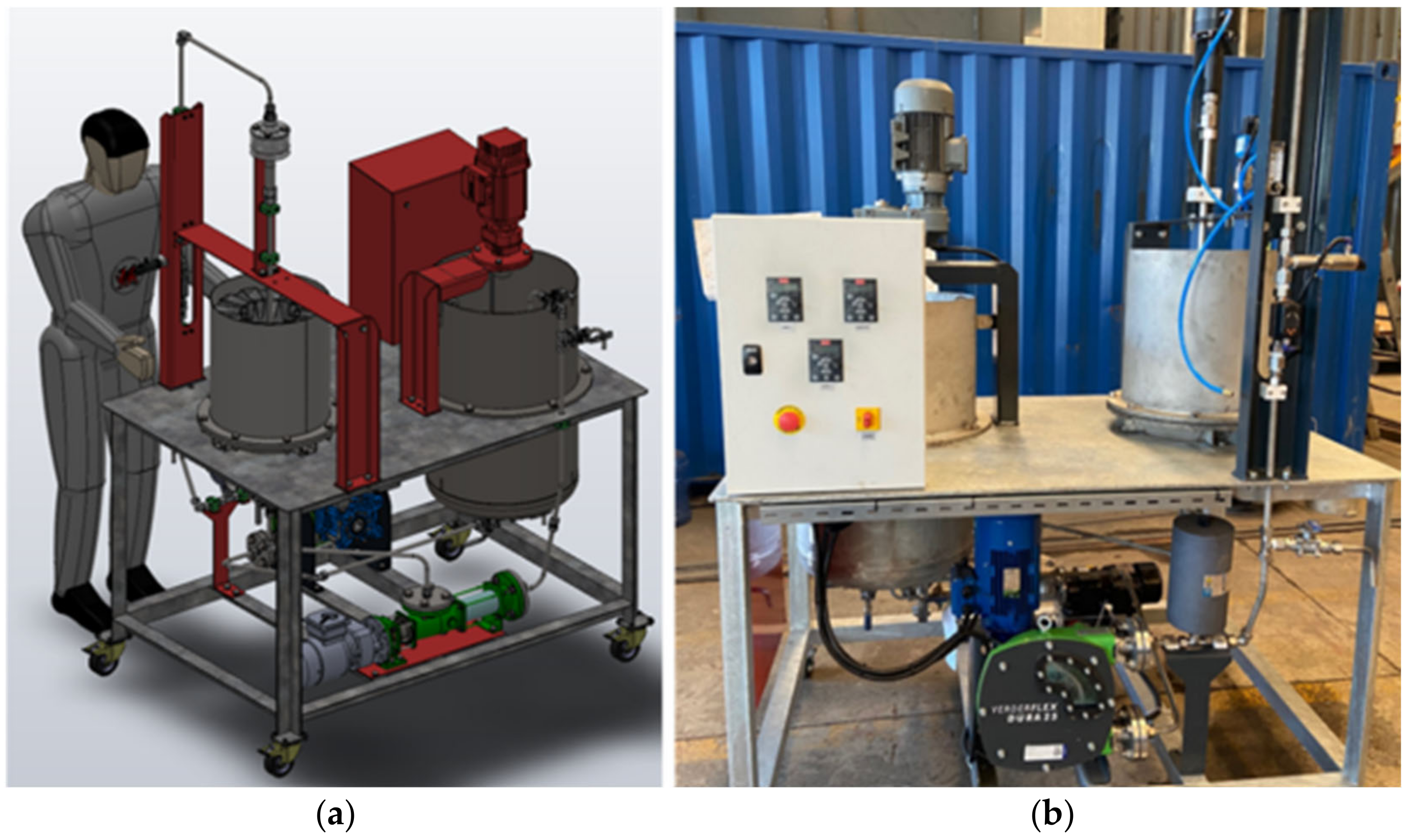
2.2. Design and Fabrication of the VM-04 Cell

The ImhoflotTM forced-air VM-04 cell (400 mm diameter, 42.1 L active volume) was designed and fabricated to treat a relatively lower amount of sample (20–40 kg) with a top size of 500 µm as a preliminary stage before industrial trials. The unit was constructed with the dimensions of 230 × 110 × 160 as height, width, and length, respectively. Figure 2a displays a 3D view of the cell and Figure 2b exhibits the designed and fabricated apparatus. Two peristaltic pumps (VERDER Dura25) were considered with a throughput in the range of 400–2000 L/h (0–1 m3/h), including the frequency inverter to adjust the pulp flowrate with the digital display. The slurry and air flowrates were measured by pulp (IFM SV7500 Vortex, 5–100 L/min) and air (Bronkhorst MV-304, 0–20 L/min) flowmeters. A conditioning tank (130 L) was equipped with a two-blade type agitator (0.75 kW).

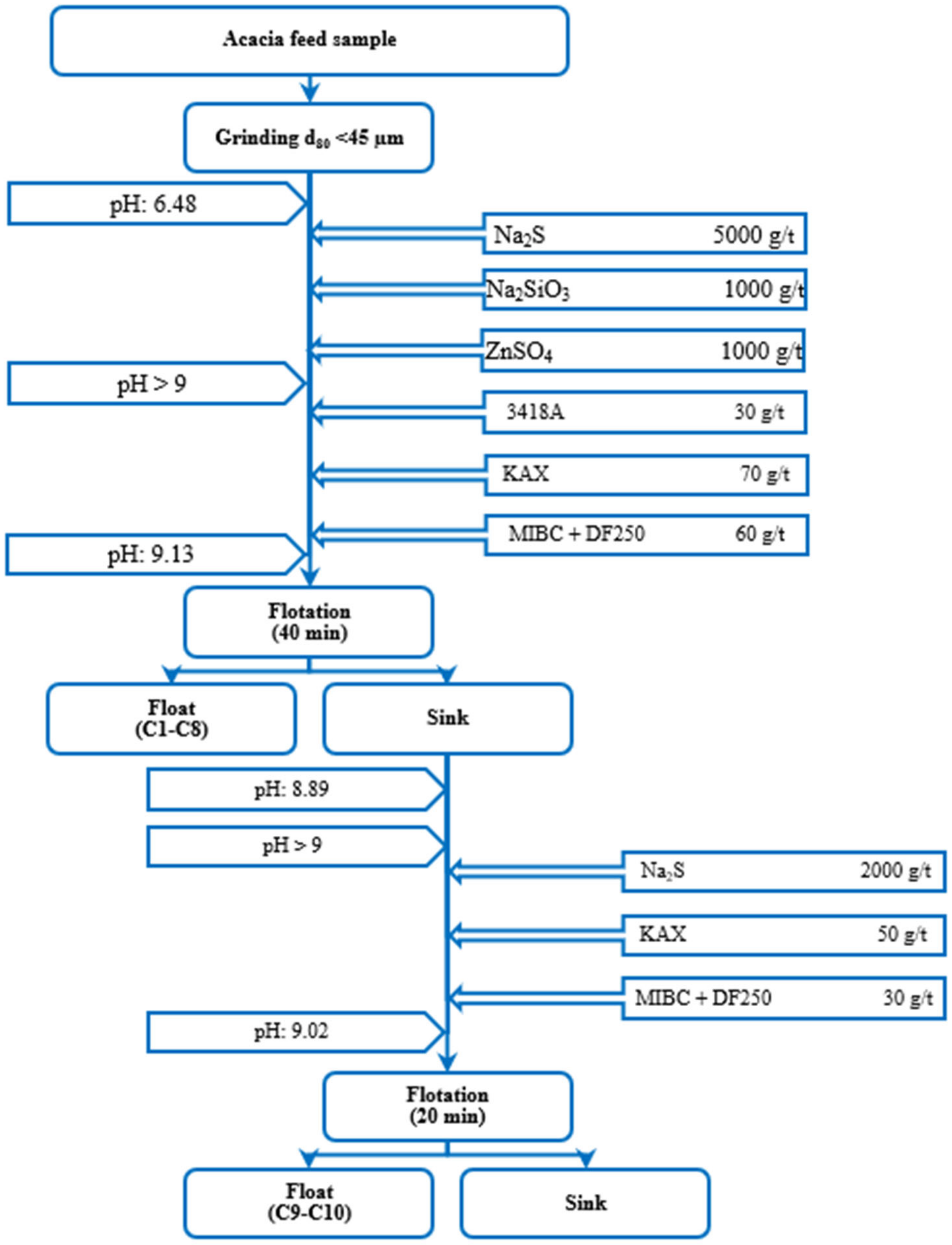
2.3. Experimental Procedure

The flotation experiments were performed using the VM-04 cell (42.1 L) combined with a conditioning tank (approximately 50 L out of 130 L was used) and a mechanical flotation cell (100 L) following the stepwise procedure given in Figure 3. The chemical reagent regime and dosages were kept constant for both pneumatic and mechanical flotation tests. Since the sample was relatively oxidized, one step of sulfurization by the Na2S with a conditioning time of 10 min was found essential. Subsequently, Na2SiO3 and ZnSO4 were added to depress pyrite and sphalerite, respectively, with another 10 min of conditioning followed by adding potassium amyl xanthate (KAX) and 3418-A (Aerophine containing dialkyl dithiophosphinates groups) as collectors (3 min conditioning) as well as MIBC and Dowfroth (with the proportional ratio of 50% each, 7 min conditioning) as frothers. Further details regarding the operating parameters of the VM-04 cell can be found in Table 1. In mechanical flotation cells, an identical solid content with the exact procedure given in Figure 3 was applied, while the agitator speed was regulated at 50 Hz (3000 rpm) and an air flowrate of 20 L/min. After adjusting the parameters and adding the reagents, the air valve was opened, and the flotation concentrates were gathered in incremental time levels up to 60 min to ensure most of the valuable minerals were recovered. The concentrates and the remaining sample in the cell (tailings) were dried, weighed, and sent for wet chemical analyses. To evaluate the flotation kinetic rates and estimate the infinitive flotation recoveries, two different flotation kinetic models were applied as Equations (2) and (3).
R ( t ) = R ( 1 exp k t )
where R(t) is the recovery (%) obtained in each time frame, R (%) is the ultimate recovery, k (min−1) is the flotation rate constant, and t is the flotation time (min).
R = R 1 1 1 + k τ n
where R is the flotation recovery in continuous operation (%), k is the flotation rate constant (min−1), R (%) is the maximum achievable recovery, n is the number of cells in the series, which is adapted as the number of cycles, and τ (min) is the retention time.

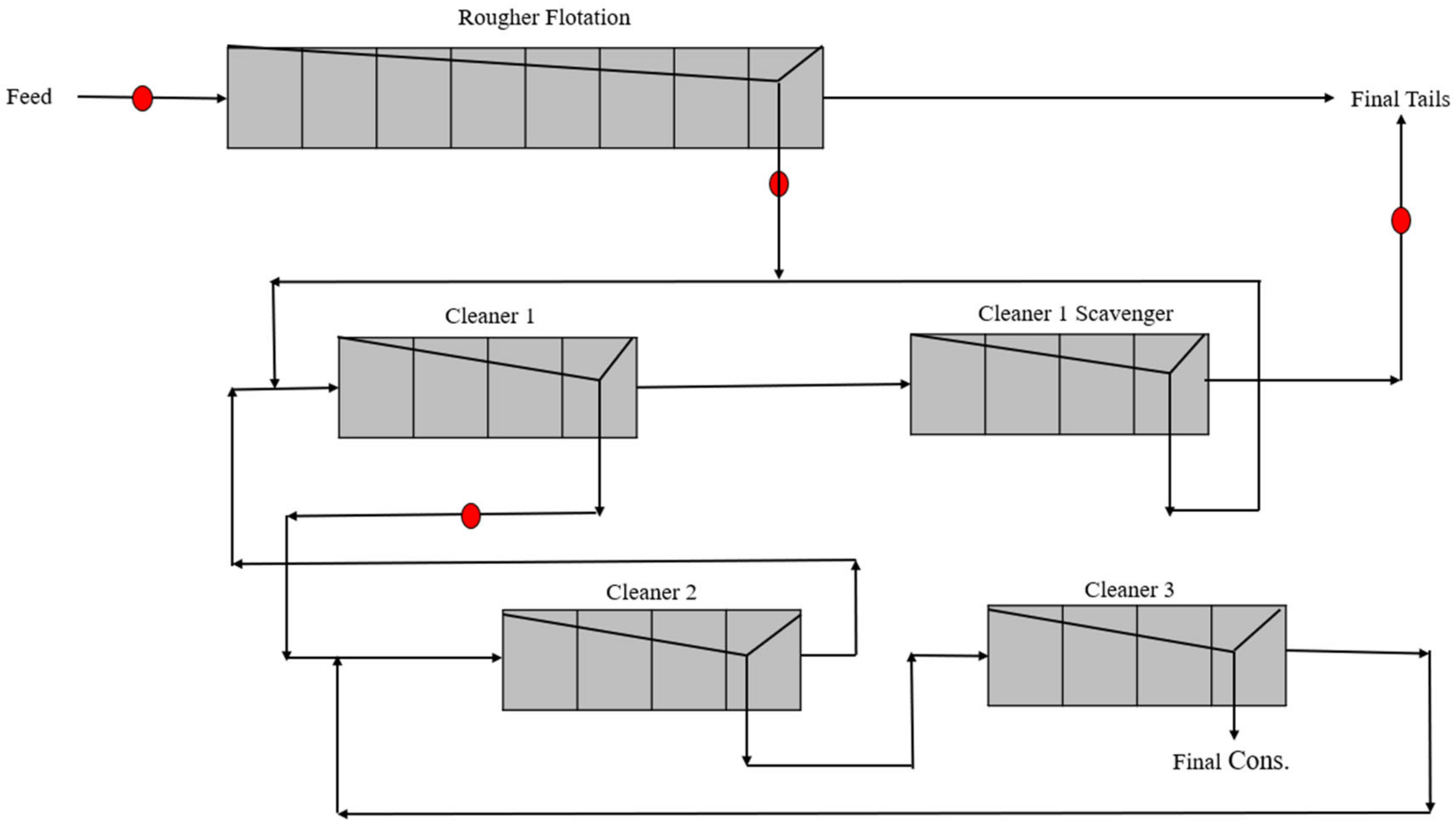
2.4. Acacia Concentration Plant

Acacia Mining Operations was established in 2007 to operate the Gökırmak Copper Mine Project in the Hanönü district of Kastamonu. According to the flowsheet of this concentration plant [36], after screening and grinding the ore, the feed particle size was reduced through a primary ball mill operated in a closed circuit with a hydrocyclone cluster to transport particles finer than 70 µm into the flotation circuit consisting of 8 mechanical cells in the rougher stage (Figure 4). The concentrate (i.e., rougher concentrate) was fed to another set of hydrocyclones to reach an overflow of approximately 20 µm as a feed to the cleaning circuit while the hydrocyclone underflow was fed to a vertical mill for re-grinding (2650 kW, and the maximum feeding capacity of 138 t/h) to reach a top particle size of 25 µm.
The rougher concentrate, after being classified by hydrocyclones and the vertical mill, was fed to the conditioning tanks (100 m3 in total) in the cleaning circuit. The cleaning phase comprised of four different stages that includes cleaner-1 (4 × 50 m3), cleaner-scavenger-1 (4 × 50 m3), cleaner-2 (4 × 20 m3), and cleaner-3 (4 × 10 m3) circuits. In addition to the PAX as the main collector, the Aero 3894 collector was fed to the cleaner-1 and cleaner-1-scavenger circuits at 8 g/t and 6 g/t, respectively (Figure 3). This additional collector was used by the recommendation of beneficiation plant managers, which is relatively different than the one utilized for laboratory test works. The total mass pull ratio of the flotation circuit varied from 6–8%, and the solid content in the pulp was ca. 23% (w/w). The final concentrate obtained after cleaning contained approximately 21% Cu.

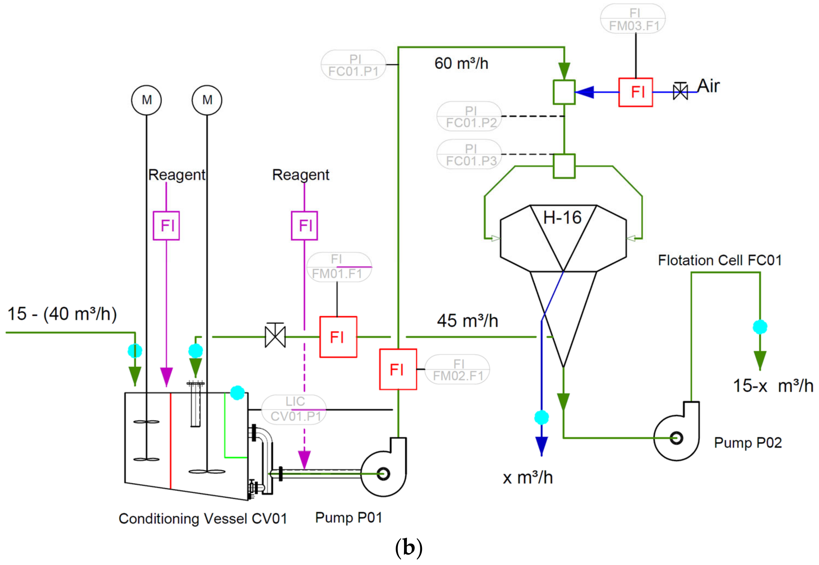
2.5. H-16 Cell and Sampling Campaign

Figure 5 displays the H-16 ImhoflotTM cell, and its components installed in the Acacia mining operation. As can be seen from Figure 4a, the unit was composed of a usual conditioning tank where the slurry was mixed by an agitator and controlled rotation speed. The solid concentration was set around 20–30% (w/w), and the pH was regulated using a sufficient amount of lime at a desirable level of 7.5–8 depending on the cell duty, and the reagents (collector and frother) were dosed accordingly. Detailed operating conditions of the H-16 cell at each location in the flotation circuit can be found in Table 2. The slurry in the conditioning tank was pumped through a feed pump to the aerator where the particle–bubble interactions occurred, particle surface coatings and surface oxidations were removed, and intensive turbulence was created (Figure 5b). The steady-state slurry condition was entered into the separator via a tangential movement, and the froth (flotation concentrate) was gathered from the center of the cell while the non-floated material was transported through the tailing pump to the conditioning tank as the recycling load. After ensuring that the cell is under steady-state conditions and the circuit is stable, samples were taken from the feed, concentrate, and tailing streams. Samples were manually collected hourly with 500 mL plastic buckets. In overall, 7–8 samples from each stream were collected and accumulated in a box during operation, depending on the test duration. The collected samples were compiled, filtered, and dried overnight, and representative specimens were analyzed by the electrolysis (for Cu > 15%) and Inductively Coupled Plasma Mass Spectrometry (ICP-MS) methods. The self-standing kit was stopped after each day of shift sampling, flushed with water, and made ready for another duty.

3. Results and Discussions

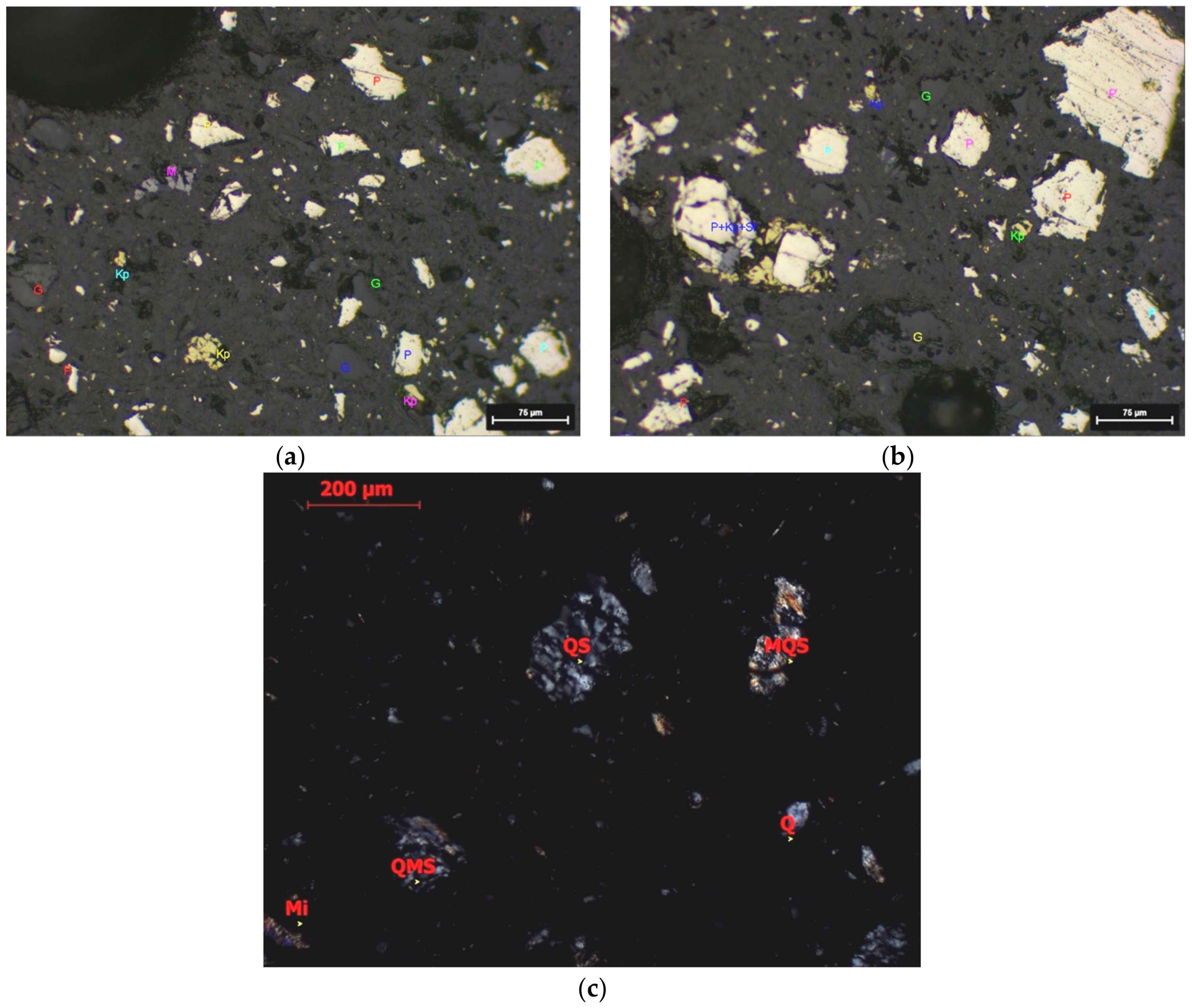
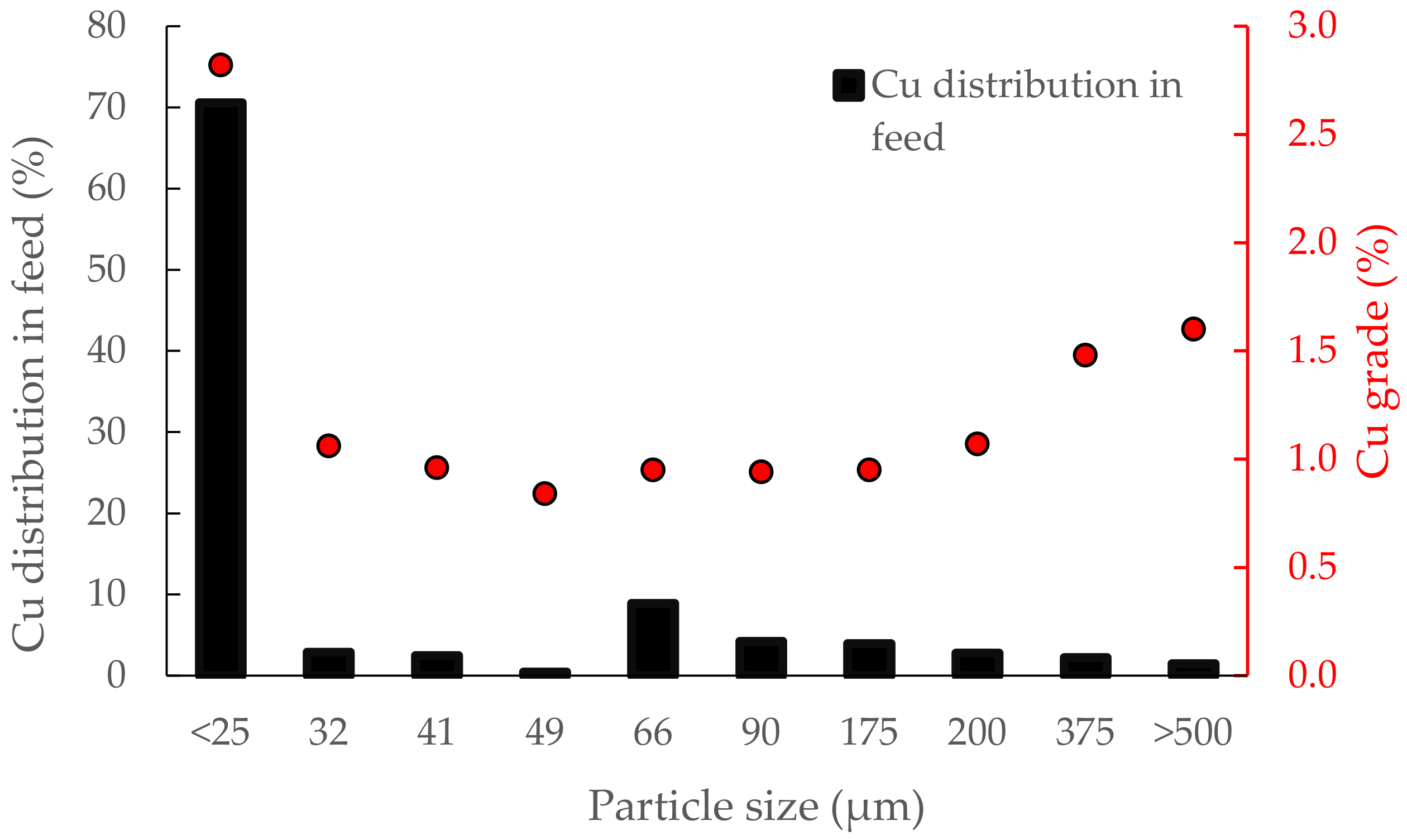
3.1. Sample Properties

According to the mineralogical observations (Figure 6), the ore was composed of a significant amount of pyrite (FeS2), low target copper-bearing mineral, chalcopyrite (CuFeS2), magnetite (Fe3O4), and sphalerite (ZnS). Binary and tertiary locked combinations of the main component pyrite with chalcopyrite (mainly varying in the range of 10–30 µm particles), gangue, and very rarely sphalerite have been observed (Figure 6b). Under the polarizing microscope, it was found that the gangue minerals were mostly composed of metamorphic rock fragments dominated by quartz-mica-schist, quartz-schist, and mica-schist fragments. In addition, muscovite-sericite-sized mica minerals and mono-polycrystalline quartz fragments derived from these rock fragments were also detected (Figure 6c). The chemical analyses of the feed sample showed that the sample contained 1.87 wt.% copper (Table 3) in total, and its distribution throughout the particle size ranges exhibited that around 70% of Cu is allocated into particles finer than 25 µm (Figure 7). It is worth noting that the particle size distribution was measured through a wet screen analysis, and the copper contents were measured using an atomic absorption spectrometer (AAS). The XRD results revealed that pyrite, quartz, kaolin, and chalcopyrite were the main detected minerals containing 48.2, 29.4, 18.3, and 4.1 wt.% of the sample.

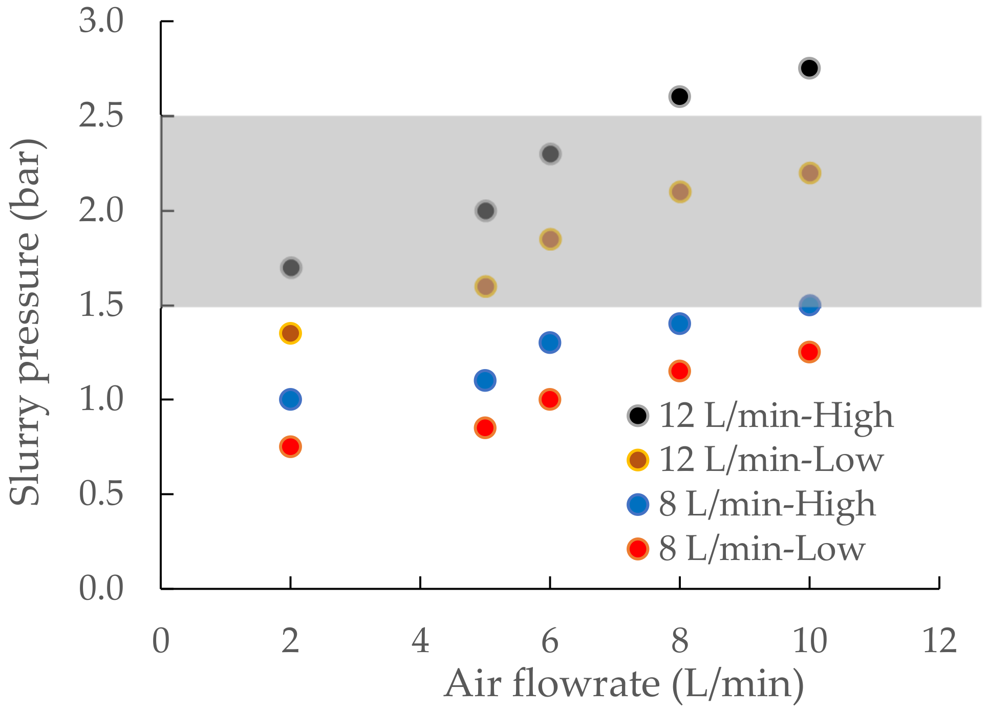
3.2. Operating Parameters of the VM-04 Cell

Prior to the flotation experiments, several trial-and-error tests were conducted using various venturi (5.5 and 6 mm) and nozzle (3.5, 3.7, and 4 mm) configurations by varying the feed (6–14 L/min) and air (2–10 L/min) flowrates to reach a head pressure of 1.5–2.5 bar (150–250 kPas) and optimize the operating parameters. The results of only using water showed that the unit was in steady-state condition at a feed-to-air flow rate ratio of 1:1, with a nozzle, and venturi diameters of 3.5 and 5.5 mm, respectively. Later, the effect of pulp density was investigated at two levels (1280 (low) and 1350 kg/m3 (high)) at the optimum operating conditions obtained through the trial-and-error tests with the installed nozzle and venturi diameters of 3.5 mm and 5.5 mm (Figure 8). As seen, feeding the slurry with 8 L/min at both pulp density levels (1280 and 1350 kg/m3) cannot create a desirable head pressure. This does not take place even with enhancing the air flowrate to 10 L/min for the same feed level. However, increasing the feed floodwater to 12 L/min with an air flowrate of 10 L/min could generate nearly 1.5–2.5 bar head pressure, which is required as the main critical criterion for the creation of a cavitation mechanism. Since the air-to-pulp ratio (APR) of 1:1 was accepted through the trial-and-error test works for this case study, the slurry flowrate of 10 L/min was recognized as the optimum feed rate. Flotation test works on the VM-04 cell were performed based on acquired values for the operating parameters as indicated in Table 1.

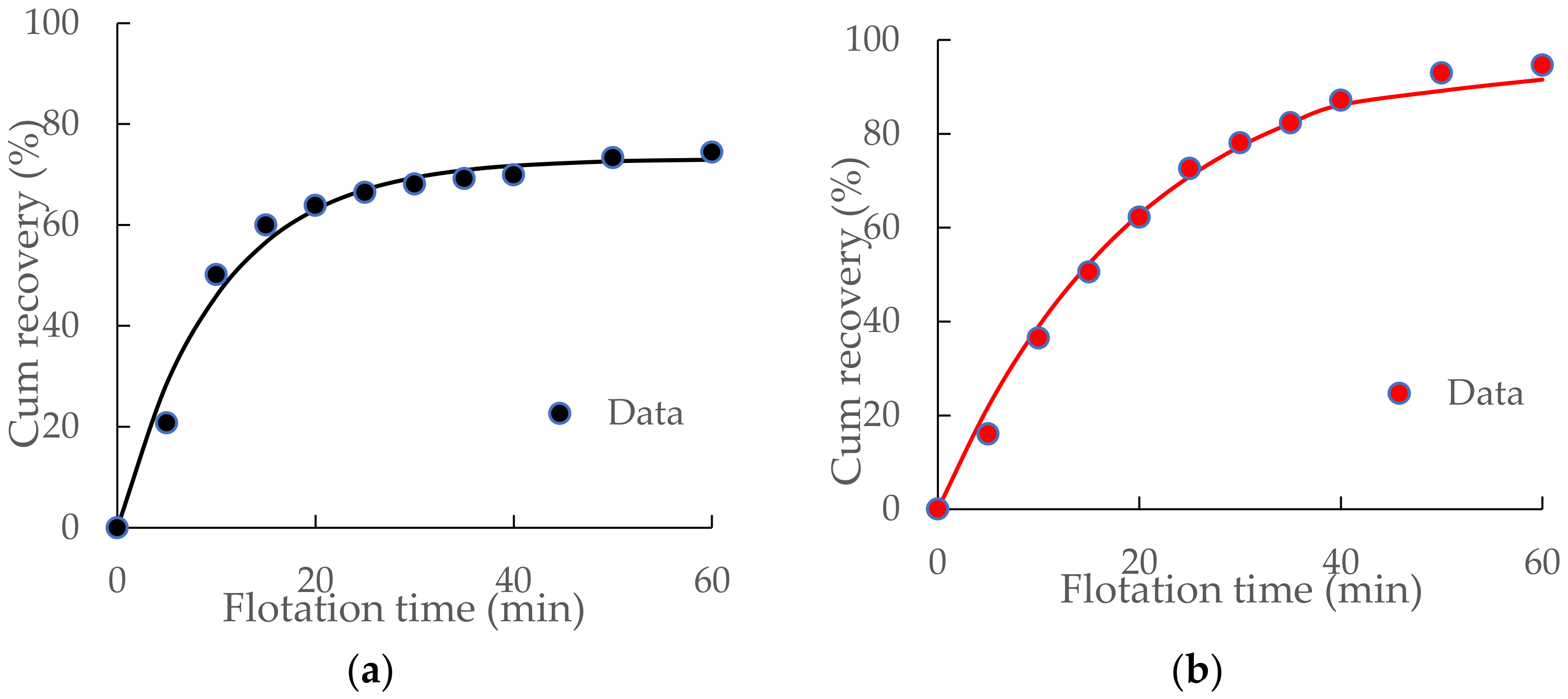
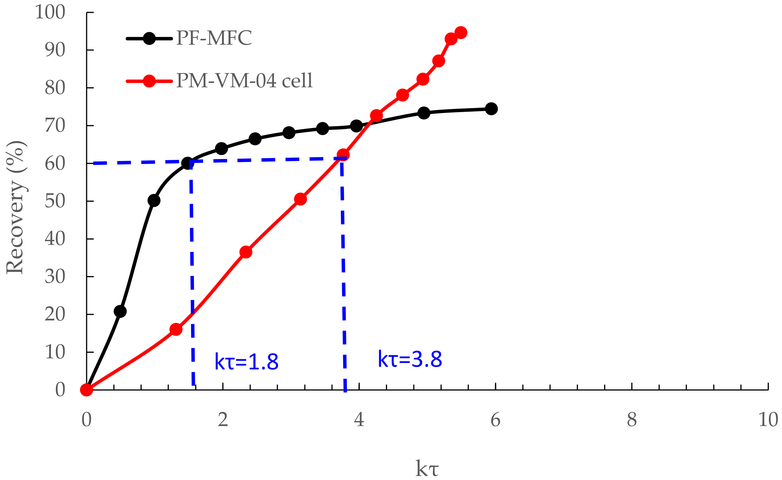
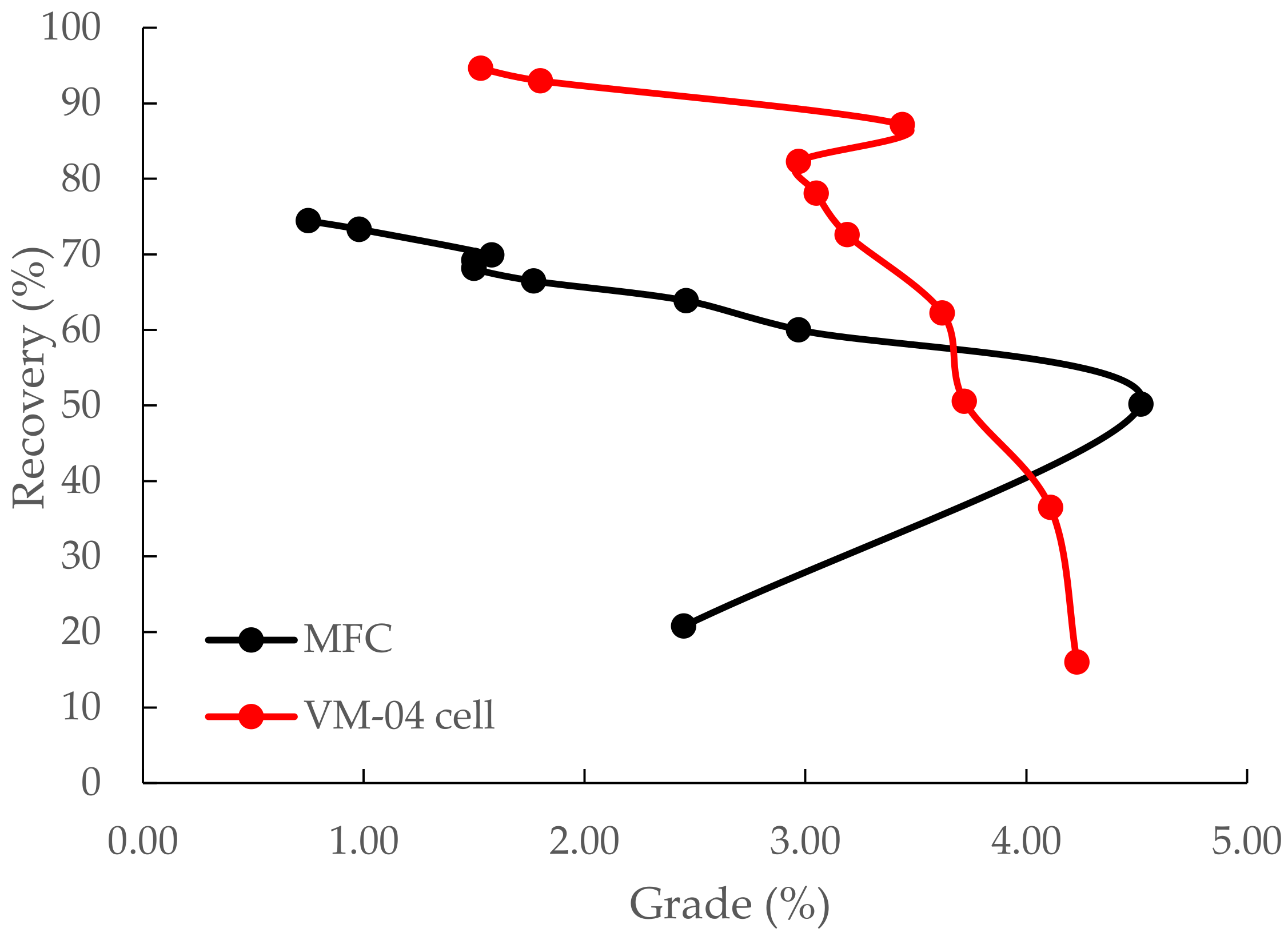
3.3. Flotation Kinetic Results of ImhoflotTM VM-04 and Mechanical Cells

Figure 9 illustrates the two models fitted to the experimentally obtained flotation kinetic data. The commonly applied first-order flotation kinetic model (Equation (2)) resulted in R of 73.15% with an estimated kinetic rate of 0.09 min−1. Equation (3) shows an R of 91.54% with a flotation rate constant of 0.06 min−1 for the ImhoflotTM cell. One reason for the low kinetic rate of 0.06 min−1 can be attributed to the long conditioning time indicated in Figure 3 leading to the surface oxidation and creation of a passivation layer on the finely disseminated particles that likely could not be overcome by the relatively low shear creation in such small cells. Also, non-optimized reagent amounts in the studied mini-pilot cell can be another plausible reason. Additionally, since the VM-04 was operated in a semi-continuous mode pumping fresh feed of 10 L/min from a conditioning tank to the flotation cell, the meaning of flotation time is different from the mechanical one, which was operated in a non-continuous mode (batch) where the entire sample was situated in the cell and target chalcopyrite minerals had the chance of being recovered. It can be concluded that presenting the flotation kinetic data as shown in Figure 9 is not an appropriate method for fair comparison between the flotation kinetics since the concept of floatation is different within these two cells and the role of fluid volume is not taken into account. That is why presenting the results of pneumatic cells in the form of cycles (viz. the number of times the total volume of the feed passes through the cell) is preferred over the flotation time. For instance, operating the laboratory-scale ConcordeTM cell at 5 L/min meant a single cycle lasted 6 min where a flotation test of 18 min was equivalent to three cycles [15]. Other conceptual ideas need to be developed to create a fair comparison, which is a matter of presentation in another work in the future.
It is known that the flotation behavior of chalcopyrite-based sulfidic copper ores follows the well-known first-order flotation kinetic model (Equation (2), Figure 9a) [37,38]. It can be seen from Figure 9b that Equation (3) represents the flotation kinetic tendency within the ImhoflotTM V-04 cell with reasonable goodness of fit, and it can be acceptable as a suitable model for the presented data. It is worth noting that to the best of the authors‘ knowledge, the kinetic modeling and flotation behavior of such ores within a reactor–separator flotation cell has not been reported in the literature yet. One major difficulty in this regard is that the particle–bubble collision and attachment subprocesses take place in the aerator (also known as downcomer) where intensive turbulences do not allow for performing photographic observations or any other empirical approaches to experimentally estimate these probabilities. Another principal challenge is that since part of the feed returns to the conditioning tank, the slurry dispersion system seemingly is not a fully plug-flow (depending on the size of the conditioning tank). Other than this, further studies should be conducted applying different existing flotation kinetic models and developing new empirical ones to evaluate their accuracies from a statistical perspective for being used for these pneumatic flotation cells.
In addition to the flotation kinetic rate, the ultimate flotation recoveries showed that the maximum recovery of 94% and 74% were achieved using the ImhoflotTM and mechanical cells, respectively. The main reason for this is related to the recirculation of the tailing back to the conditioning tank and later to the ImhoflotTM flotation cell allowing unrecovered (possibly slow-floating: middling ones) particles to have the chance of being recovered. The recirculation has been applied mainly to create the head pressure of 1.5–2.5 bar required for the generation of the cavitation within the aerator not only in the ImhoflotTM cells but also in almost all pneumatic cells present on the market. That is why most of the applications of ImhoflotTM flotation cells in industrial levels need to be operated with high recirculation mode in the pre-flotation and rougher stages [9], while circulating load should be applied as little as possible in the cleaning and re-cleaning stages. It is worth noting that the concept of recirculation for these cells has not been fundamentally well presented and accepted in the literature yet. Further developments for its impact on the metallurgical responses and scale-up procedures should be considered as well as its modeling, which needs to be included in the flotation circuit design software packages.
Figure 10 displays the time-based recoveries versus graph, where the k-values were obtained using Equations (2) and (3). This approach is presented to have a relatively fair comparison between the kinetic results of the ImhoflotTM and the mechanical cells because the concept of flotation time in these two cells is not identical. By assuming that the mechanical flotation cell (MFC) and the VM-04 cell follow the plug-flow (PF) and perfect mixing (PM) dispersion patterns, respectively, this concept can be utilized for comparing the results of flotation kinetic tests. It can be seen from Figure 10 that in order to reach a recovery of 60%, the non-dimensional values should be 1.8 and 3.8 for the mechanical and VM-04 cells, respectively. It implies that the retention time for the mechanical cell is 1.2 times faster than the ImhoflotTM cell. In other words, the required volume of ×2.1 should be considered if the ImhoflotTM cell provides the same 60% recovery obtained using the mechanical cell. Indeed, the retention time on the industrial scale for ImhoflotTM cells is in the range of 5–8 times higher than the mechanical ones similar to the RefluxTM flotation cells [18], meaning the scale-down remains an ongoing challenge in the development of pneumatic cells. Another proof for this is the results presented in Section 3.4 where one H-16 cell provides similar metallurgical responses equaled to the number of mechanical cells in a series. It is anticipated that on an industrial scale, the dispersion regime becomes plug-flow, and faster flotation kinetics can occur due to an efficient shear effect. However, this is relatively challenging to be achieved in smaller cell sizes. In this regard, Guner et al. [39] measured the residence time distribution in a two-phase (liquid-gas) system for a V-03 cell (4–5 L/min feed flow rate and 3–5 L/min air flow rate), which performed similarly to the VM-04 and acknowledged the perfect mixing dispersion system within the cell in the absence of recirculation, while a frit-type aerator (old design) was used for this unit.
Figure 11 presents the copper grade-recovery curve for both cell types. Despite relatively high recoveries obtained through these flotation kinetic tests for both cell types, the copper grade was not naturally improved significantly. As noted above, the higher recoveries acquired through the VM-04 cell can be mainly related to the greater mass pulls obtained because of recirculating the tailing back to the conditioning tank as the new feed to the cell. Thus, it makes the process less selective and eventually leads to the reduction of the grade. Another plausible reason can be that the cell operating properties and more specifically the air-to-feed ratio were beyond the optimum range, which requires further test work. Relatively higher air input can result in greater recovery but has a deleterious impact on the grade. It is worth mentioning that in contrast with all pneumatic flotation cells on the market, no wash water is considered for the ImhoflotTM cell designs. Therefore, it is recommended to consider adding wash water at least in the cleaning and re-cleaning stages in order to lift up the grade. Another fact is that a similar amount of frothers was used to be identical with the mechanical cells; however, the number of generated small bubbles via the cavitation mechanism is way greater than the mechanical cells, indicating a high consumption of frother dosage. Aside from all these, the flotation tests need to be repeated for the sake of obtaining the experimental errors.

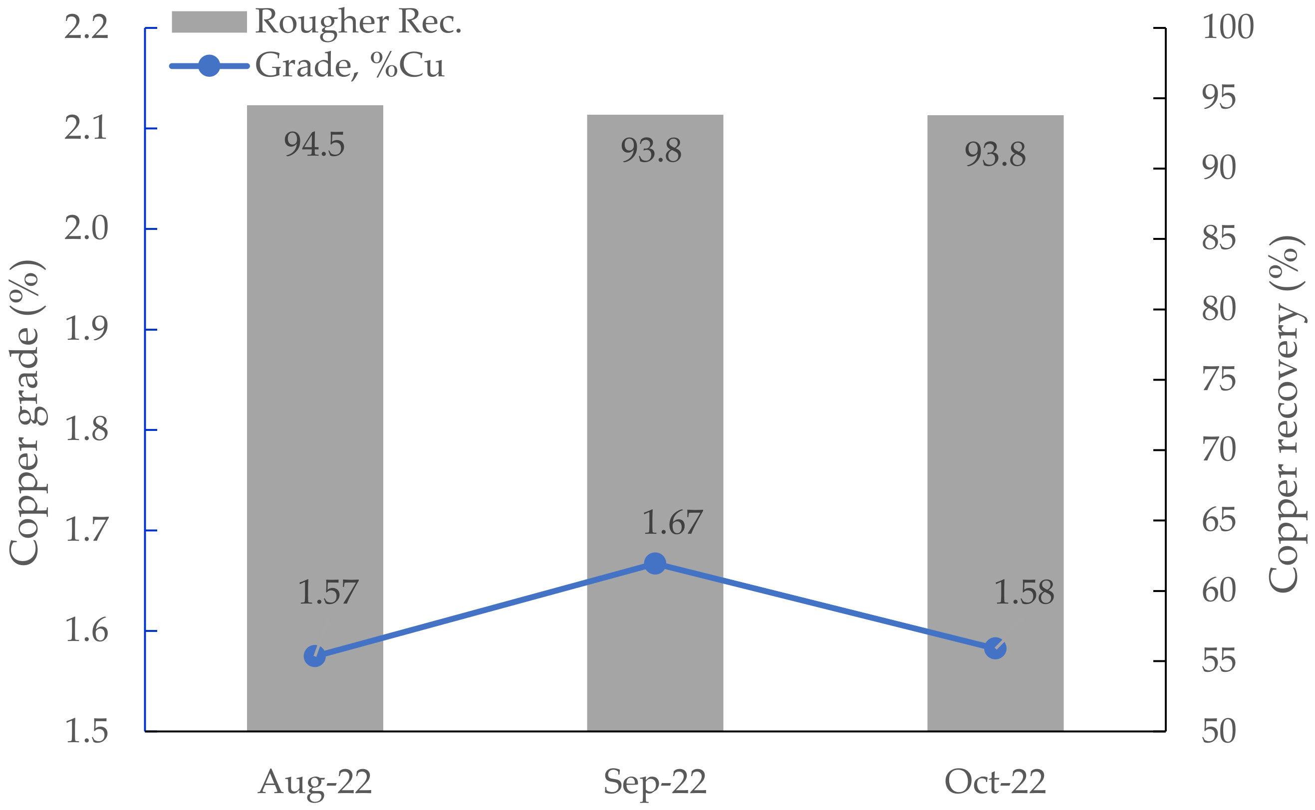
3.4. Results of Industrial Surveys

The ImhoflotTM cell was positioned in several stages of the flotation circuit including (i) pre-flotation, (ii) rougher concentrate, (iii) cleaner-scavenger tailings, and (iv) first cleaning concentrate stages aiming at enhancing the flotation circuit capacity through flash flotation in the rougher stage, reducing copper grade in the final tailings, and increasing cleaning throughput, respectively. The operation took place from August to October 2022, and the exact locations of the H-16 cell are shown in Figure 4. The monthly flotation copper grade of the flotation feed and the rougher recovery are exhibited in Figure 12. As seen, the rougher recovery varied between 93–94%, the P80 varied between 63–70 µm, and the copper feed grade was in the range of 1.5–1.7%.
Table 4 represents the copper upgrade ratio, also known as the enrichment ratio (ER, i.e., concentrate grade (c) divided by the feed grade (f)), and its recovery for both one H-16 cell and conventional flotation cells. A relatively significantly higher copper enrichment ratio was obtained by positioning the ImhoflotTM cell at the pre-rougher stage compared to the series of eight conventional cells. Through this, it was possible to recover the easy-to-float chalcopyrite particles (fully to mostly liberated ones) from the flotation circuit and send them directly to the cleaning stage. This eventually resulted in an increase in flotation throughput and prevented unnecessary circulation of particles in the rougher and cleaner-scavenger and cleaning streams, which avoided surface oxidation of chalcopyrite particles due to their massive specific surface areas and ultimately their poor recoveries. As can be seen, the average copper recovery of 89% (85–93%) was obtained using only one H-16 cell while this value was approximately 96% using the mechanical cells. It is very natural to observe that the mechanical cell‘s performance is very effective because the feed P80 varied between 63–70 µm, which is an optimum range for the chalcopyrite particle. To be more precious in terms of comparison, first the rougher cells’ grade and recoveries should be sampled and compared with the H-16 cell results. Furthermore, one needs to deeply pay attention to the retention time of the circuit. Since a moderate to high recirculation load is considered for the pre-rougher stage, to increase the recovery of the H-16 cell, one additional cell positioned in a series with the existing cell might be very beneficial. The theoretically calculated retention time of the ImhoflotTM cell without any recirculation load was 5.92 min ((1.48 m3) × 60/(15 m3/h)) based on the well-known equation (i.e., τ = V e f f e c t i v e Q × 60 ) where the τ (min) is the theoretical mean retention time, Veffective (m3) is the effective volume of the cell, and the Q (m3/h) is the volumetric flowrate. By considering the circulating load into the account, the mean retention time would be (1.48/41) × 60 = 2.16 min, whereas the nominal respective value for the existing rougher cells was 32.5 min with the gas hold-up and froth volume percentages of 10% and 5% (v/v), respectively. It can be concluded that the industrial metallurgical results were greater than the values obtained in the mini-pilot scale using the VM-04 cell. One reason for this is attributed to the efficiency of the shear effect. In other words, due to more effective shear creation at greater flowrates (applied for the H-16 cell), the slime coatings and passivation layers could be effectively removed, leading to superior adsorption of collectors on the target chalcopyrite surfaces and eventually favorable recovery and grade.
Locating the ImhoflotTM at the rougher concentrate resulted in an upgrade ratio and recovery of 2.97 and 61%, respectively. Since fine and ultrafine particles require a relatively long flotation time to be recovered, they move to the tailing unavoidably due to a few reasons, including slime coatings, a low number of designed flotation cells in rougher and scavenger banks, and non-optimized operating parameters [40]. Another important position was the cleaner-1-scavenger tailings, which contain the major proportion of the tailings stream. Poor recoveries in this circuit can result in losing copper-containing particles to the tailings. By situating only one H-16 cell, the ImhoflotTM could recover copper particles with a magnitude of 38% and an ER of 2.67, which is highly beneficial considering its significant flowrate. It is worth mentioning that for this stream, the vertical nozzles were closed and only the tangential fluid movement was applied, which converted the H cell to the G cell type. Figure 13 displays the mineralogical characteristics of the scavenger tailings where pyrite is mostly the liberated mineral, which could be evidently observed. Pyrite was detected as the predominant problematic metallic mineral of ore. Chalcopyrite was identified with a liberation degree of about 40%, and the sphalerite was found partially liberated and mainly interlocked with pyrite. Such high pyritic feed can lead to process complexities and lower the flotation grade after all. Several mechanisms are presented in the literature in terms of serious challenges of elevated-pyritic ores in chalcopyrite floatation [41,42]. Another example of using ImhoflotTM cells at the scavenger tailing was an improvement in the recovery of Ni through the installation of three G12-Cells in series at the Aguablanca Nickel-Copper Mine, Spain, particularly for particles finer than 11 µm [33].
As seen in Table 4, the obtained copper recovery and enrichment ratio by the ImhoflotTM cell were higher than those values acquired through four mechanical cells in series (4 × 50 m3) in the cleaner-1 concentrate duty. To reach 64% recovery, the VM-04 cell required a flotation time of ca. 22 min, while in 2.1 min (i.e., 1.48 m3 × 60/41 m3/h) approximately the same recovery magnitude was obtained at a continuous industrial level at this stage indicating a difference of ca. 10-fold in the scale. That indeed demonstrates the effectiveness of such cells on larger scales than the laboratory level, ensuring that the feed properties of both cases must be identical (Figure 4). Needless to mention, parameters such as air-to-feed ratio, reagent regime, and conditioning were not considered, and one needs to include those in this concept. One main reason for the low recovery of copper in the cleaner stage using the mechanical cells is attributed to the surface oxidation of chalcopyrite particles due to the long treatment process. Another reason can be the nature of fine and ultrafine particles as the collector rubbers and their readily high collector dosage requirements for being recovered. Further reasons for poor recovery of fine and ultrafine particles can be found elsewhere [43,44]. However, since the H-16 cell provided a high shear intensity on the aerator, the surface oxidation layers as well as slime coatings could be removed, which led to favorable adsorption of reagents on the particle surfaces and ultimately grade and recovery improvements. Since there was only one H-16 cell in operation, recirculation (recycling flotation tailings to the feed) should be considered to obtain a reasonable recovery, which could potentially reduce the copper grade. In other words, the presence of two H-16 cells in series with low recirculation load could feasibly induce significantly higher copper grade in the cleaner stage compared to the mechanical cells.

4. Conclusions and Future Works

The present study presents the design and fabrication of an ImhoflotTM VM-04 cell for the sake of treating/floating 20–40 kg solid particles as a primary stage before conducting industrial trials. To this end, the impact of some of the key operating parameters including venturi and nozzle diameter, feed and gas flowrates, and pulp density were investigated. As a case study for metallurgical purposes, the chalcopyrite-bearing sample was taken from Gökirmak copper flotation circuit (Acacia Mining Operations, Türkiye) and ground to d80 of 45 µm, which was afterward floated under identical chemical reagent regimes using one Tüfekçioğlu mechanical flotation cell (50 L) and VM-04 cell (42.1 L). Further, several trials were conducted using one self-aspirated ImhoflotTM H-16 cell for Gökırmak Copper Mine of Acacia Mining Operations. To evaluate the performance of the ImhoflotTM pneumatic flotation cell, it was located at four different duties in the flotation circuit. The following conclusions were drawn from the results as the key highlights:
The forced-air self-standing kit was optimally operated at a 1:1 feed-to-air ratio (10 L/min) with nozzle and venturi diameters of 3.5 mm and 5.5 mm, where the head pressure in the range of 1.5–2.5 bar was achievable for the creation of cavitation, intensive turbulence, and fine bubbles within the aerator.
Copper recovery of 94% was achieved using the VM-04, while the corresponding value was 74% using the mechanical cell. Low-grade improvement was reported for both cells and the attributed reasons were addressed in detail.
Flotation recovery versus was presented as a new approach for comparing the performance of two different cells where the dispersion regime of the V-04 cell was found to be not a plug-flow dispersion, most likely because of the high recirculation load.
Industrial surveys showed that only one H-16 cell could be beneficially used as a flash-flotation to recover copper with a magnitude of 89% and upgrade ratio of 4.84, which could be directly sent to the cleaner stage. Through this, the inlet capacity of the flotation circuit could be substantially increased.
The results revealed that locating one ImhoflotTM cell at the cleaner stage resulted in a copper recovery of 64%, while four mechanical cells (50 m3, each cell) led to a 60% copper recovery with an even slightly lower enrichment ratio. This showed that one H-16 cell can be equal to four conventional cells in the cleaning stage for this case study and can effectively recover fine particles.
Further experimental works need to be conducted in order to create a relationship between the laboratory, pilot, and industrial scales in terms of scale-up and/or scale-down factors for the ImhoflotTM and other pneumatic flotation cells.
Since a limited amount of information is available in the literature and given in this article in terms of the impact of froth properties on the final grade and recoveries, future test works should be performed to evaluate the role of froth level in flotation efficiency of such pneumatic cells.
Different flotation kinetic models should be applied for the case of pneumatic cells in various scales and their accuracies must be evaluated further in the future before accepting one kinetic model as the most representative one.
The results presented in this work are more specific for the ore type studied and should not be generally accepted because the flotation behavior varies from one commodity to another. Further test works must be performed on different commodities in the future.
The concept of recirculation in the pneumatic flotation cells is not clear to the community, and its impact on the grade and recovery as well as its optimum percentage in various flotation stages needs further in-depth investigation. Its effect on scale-up procedures must be taken into account and addressed in future works as well.
The given results in the literature showed that total dispersion regimes vary among the pneumatic flotation cells in pilot scales, and there is very little information available on an industrial scale. Future studies need to investigate this concept further paying close attention to the role of recirculation and its magnitude.
It is recommended to compare the concentrates of the first and/or first and second mechanical flotation cells with the H-16 cell performance in terms of the grade.
One possible reason for the low enrichment ratio in the V-04 cell was related to the absence of wash water in the ImhoflotTM cell design, which is indeed considered an advantage of this cell over other pneumatic cells. Future test works should be carried out to study its impact on the metallurgical responses.
Since the weight percentage of the solid was considered in the flotation tests, while the volume of the VM-04 cell (conditioning tank with the cell itself) is different than the mechanical one, the volumetric percentage of the slurry was suggested for future works.

Author Contributions

Conceptualization, A.H.; validation, A.H., E.G., D.H.H. and E.S.; investigation, A.H., D.D. and L.V.; resources, D.D., E.G. and E.S.; writing—original draft preparation, A.H.; writing—review and editing, A.H., D.H.H. and L.V.; visualization, A.H., D.H.H., E.G. and E.S.; supervision, A.H. All authors have read and agreed to the published version of the manuscript.

Funding

This research received no external funding.

Data Availability Statement

Data will be made available by request.

Acknowledgments

We are genially thankful to the staff of Maelgwyn Mineral Services and the R&D department of ARGETEST Mineral Processing as well as Acacia Mining Operations for their continuous assistance in supporting this research.

Conflicts of Interest

Authors A.H., E.G. and D.H.H. were employed by the Maelgwyn Mineral Services Ltd. Authors E.S. and D.D. were employed by the Analysis Services Ltd. The remaining authors declare that the research was conducted in the absence of any commercial or financial relationships that could be construed as a potential conflict of interest.

References

  1. Trahar, W.J. A rational interpretation of the role of particle size in flotation. Int. J. Miner. Process. 1981, 8, 289–327. [Google Scholar] [CrossRef]
  2. Yang, Y.; Han, D.; Shen, Z.; Shi, S. Hydrodynamic and Metallurgical Evaluation of the 680 m3 Flotation Cell in Industrial Application. In Proceedings of the Flotation ’19, Cape Town, South Africa, 11–14 November 2019. [Google Scholar]
  3. Yianatos, J.; Vallejos, P. Limiting conditions in large flotation cells: Froth recovery and bubble loading. Miner. Eng. 2022, 185, 107695. [Google Scholar] [CrossRef]
  4. Finch, J.A.; Tan, Y.H. On limits to flotation cell size. Minerals 2023, 13, 411. [Google Scholar] [CrossRef]
  5. Harbort, G. Pneumatic Flotation, Chapter 7.3. In SME Mineral Processing and Extractive Metallurgy Handbook, Society for Mining, Metallurgy, and Exploration (SME); ASM International: Cleveland, OH, USA, 2019; pp. 931–957. [Google Scholar]
  6. Hassanzadeh, A. A short Pragmatic Overview on the Development of Flotation Machines from Historical, Mechanical and Metallurgical Perspectives. In Proceedings of the 9th International Congress of Mining Machinery and Technologies, Izmir, Türkiye, 13–15 September 2023; pp. 10–15. [Google Scholar]
  7. Hassanzadeh, A.; Safari, M.; Hoang, D.H.; Khoshdast, H.; Albijanic, B.; Kowalczuk, P.B. Technological assessments on recent developments in fine and coarse particle flotation systems. Miner. Eng. 2022, 180, 107509. [Google Scholar] [CrossRef]
  8. Harris, C.C.; Chakravarti, A.; Degaleesan, S.N. A recycle flow flotation machine model. Int. J. Miner. Process. 1975, 2, 39–58. [Google Scholar] [CrossRef]
  9. Hoang, D.H.; Imhof, R.; Sambrook, T.; Bakulin, A.E.; Murzabekov, K.M.; Abubakirov, B.A.; Baygunakova, R.K.; Rudolph, M. Recovery of fine gold loss to tailings using advanced reactor pneumatic flotation ImhoflotTM. Miner. Eng. 2022, 184, 107649. [Google Scholar] [CrossRef]
  10. Huynh, L.; Araya, R.; Seaman, D.R.; Harbort, G.; Munro, P.D. Improved cleaner circuit design for better performance using the Jameson cell. In Proceedings of the 12th AUSIMM Mill Operator’s Conference, Townsville, Australia, 1–3 September 2014; pp. 141–152. [Google Scholar]
  11. Hassanzadeh, A.; Safari, M.; Khoshdast, H.; Güner, M.K.; Hoang, D.H.; Sambrook, T.; Kowalczuk, P.B. Introducing key advantages of intensified flotation cells over conventionally used mechanical and column cells. Physicochem. Probl. Miner. Process. 2022, 58, 155101. [Google Scholar] [CrossRef]
  12. Wills, B.A.; Finch, J. Froth Flotation. In Wills’ Mineral Processing Technology: An Introduction to the Practical Aspects of Ore Treatment and Mineral Recovery, 8th ed.; Butterworth-Heinemann: Oxford, UK, 2015; pp. 265–380. [Google Scholar]
  13. Guner, M.K.; Hassanzadeh, A.; Vinnett, L.; Yianatos, J.; Kowalczuk, P.B. Effects of operating parameters on residence time distribution in a REFLUX flotation cell. Miner. Eng. 2023, 204, 108439. [Google Scholar] [CrossRef]
  14. Vinnett, L.; Yianatos, J.; Hassanzadeh, A.; Díaz, F.; Henríquez, F. Residence time distribution measurements and modeling in an industrial-scale Siemens flotation cell. Minerals 2023, 13, 678. [Google Scholar] [CrossRef]
  15. Yanez, A.; Kupka, N.; Tunç, B.; Suhonen, J.; Rinne, A. Fine and ultrafine flotation with the Concorde CellTM—A journey. Miner. Eng. 2024, 206, 108538. [Google Scholar] [CrossRef]
  16. Huynh, L.; Kohli, I.; Osborne, D.; De Waal, H.; Walstra, C. Design and performance aspects of coal flotation –experiences with the Jameson cell. Jameson Cell-2020 Compend. Tech. Pap. 2020; 185–196. [Google Scholar]
  17. Tabosa, E.; Vianna, S.; Valery, W.; Duffy, K.; Holtham, P.; Pyle, L.; Andrade, B. Modeling pneumatic flotation cells for circuit design and optimization. In Proceedings of the XXX International Mineral Processing Congress, Cape Town, South Africa, 18–22 October 2020; pp. 3081–3091. [Google Scholar]
  18. Parkes, S.; Wang, P.; Galvin, K.P. Investigating the system flotation kinetics of fine chalcopyrite in a REFLUX™ flotation cell: Part II low-grade ores. Miner. Eng. 2024, 207, 108548. [Google Scholar] [CrossRef]
  19. Metso Outotec Corporation. Section 4—Separations, Metso Minerals. In Basics in Minerals Processing, 5th ed.; Metso: Montreal, QC, Canada, 2006. [Google Scholar]
  20. Parkes, S.; Wang, P.; Galvin, K.P. Revisiting a flotation cell benchmark. Miner. Eng. 2023, 200, 108134. [Google Scholar] [CrossRef]
  21. Pyle, L.; Tabosa, E.; Vianna, S.; Sinclair, S.; Valery, W. Future (and Present) Trends in Circuit Design. In Proceedings of the IMPC Asia-Pacific 2022, Melbourne, Australia, 22–24 August 2022; pp. 1068–1083. [Google Scholar]
  22. Seaman, D.R.; Burns, F.; Adamson, B.; Seaman, B.A.; Manton, P. Telfer Processing Plant Upgrade-the Implementation of Additional Cleaning Capacity and the Regrinding of Copper and Pyrite Concentrates. In Proceedings of the 11th AusIMM Mill Operators’ Conference, Tasmania, Australia, 23–31 October 2012; The Australian Institute of Mining and Metallurgy: Melbourne, Australia, 2012; pp. 373–381. [Google Scholar]
  23. Dickinson, J.; Dabrowski, B.; Lelinski, D.; Christodoulou, L.; Galvin, K. Pilot Trial of a New High-Rate Flotation Machine; Procemin-Geomet: Santiago, Chile, 2019. [Google Scholar]
  24. Vinnett, L.; Yianatos, J.; Díaz, F.; Hassanzadeh, A. Estimating effective volumes in industrial forced-air flotation cells. Miner. Eng. 2024, 211, 108678. [Google Scholar] [CrossRef]
  25. Hoang, D.H.; Kurzydło, P.; Kwiatkowski, P.; Imhof, R.; Hassanzadeh, A.; Pereira, L.; Rudolph, M. Application of Pneumatic ImhoflotTM G-Cell in Recovering Fine Particles: A Case Study of KGHM Copper Ore. In Proceedings of the MEI Conferences, Cape Town, South Africa, 4–7 November 2023. [Google Scholar]
  26. Bahr, A.; Ludke, H.; Mehrhoff, F. The development and introduction of a new coal flotation cell. Proc. CIM Bull. 1970, 75, 84. [Google Scholar]
  27. Alizadeh, A.; Simonis, W. Flotation of finest and ultra-finest size coal particles. Aufbereit.-Tech. 1985, 6, 363–366. [Google Scholar]
  28. Imhof, R.M.; Battersby, M.J.G.; Brown, J.V.; Lotzien, R.M.; Kleefeld, J. Development of Pneumatic Flotation Incorporating Centrifugal Separation. In Proceedings of the XXII International Mineral Processing Congress, Cape Town, South Africa, 28 October 2003. [Google Scholar]
  29. Hassanzadeh, A.; Cinar, Y.A.; Gungor, E.; Hoang, D.H. Application of a Self-Aspirated ImhoflotTM H-16-Cell in a Copper Flotation Circuit. In Proceedings of the 2023 IMCET, Antalya, Türkiye, 28 October–1 December 2023; Volume 1133, p. 1141. [Google Scholar]
  30. Imhof, R.; Battersby, M.; Parra, F.; Sanchez-Pino, S. The Successful Application of Pneumatic Flotation Technology for the Removal of Silica by Reverse Flotation at the Iron Ore Pellet Plant of Compañía Minera Huasco, Chile. In Proceedings of the Centenary of Flotation Symposium, Brisbane, Australia, 6–9 June 2005; pp. 1–8. [Google Scholar]
  31. Lima, P.N.; Peres, A.E.C.; Goncalves, T.A.R. Comparative evaluation between mechanical and pneumatic cells for quartz flotation in the iron ore industry, REM. Int. Eng. J. Ouro Pereto 2018, 71, 437–442. [Google Scholar] [CrossRef]
  32. Imhof, R.; Fletcher, M.; Vathavooran, A.; Singh, A. Application of Imhoflot G-Cell centrifugal flotation technology. J. South. Afr. Inst. Min. Metall. 2007, 107, 623–631. [Google Scholar]
  33. Battersby, M.; Battersby, R.M.; Flatman, S.; Imhof, R.; Sprenger, H.; Bragado, T. Recovery of Ultrafine Using Imhoflot Pneumatic Flotation—Two Pilot Plant Case Studies Recovering Nickel and Zinc From Tailings Streams. 2011. Available online: https://www.maelgwyn.com/wp-content/uploads/2016/04/Recovery_of_Ultra_fines.pdf (accessed on 30 January 2024).
  34. Imhof, R.M.; Lotzien, R.M.; Sobek, S. Pneumatic Flotation: A Reliable Procedure for a Correct Plant Layout. In Proceedings of the XVIII International Mineral Processing Congress, Sydney, Australia, 23–28 May 1993; pp. 971–978. [Google Scholar]
  35. Hassanzadeh, A.; Gungor, E.; Samet, E.; Durunesil, D.; Hoang, D.H.; Köse, B. A Comparative Study between ImhoflotTM and Mechanical Flotation Cells. In Proceedings of the MEI Conferences, Cape Town, South Africa, 4–7 November 2023. Flotation 23. [Google Scholar]
  36. Bayraktar, Z.; Ayhan, R.; Baharlı, A. Improving the fine flotation recovery of fine particles with magnetic conditioning technology. 2022. [Google Scholar]
  37. Duan, J.; Fornasiero, D.; Ralston, R. Calculation of the flotation rate constant of chalcopyrite particles in an ore. Int. J. Miner. Process. 2003, 72, 227–237. [Google Scholar] [CrossRef]
  38. Asghari, M.; Salmani Nuri, O.; Allahkarami, E. Analysis of kinetic models for chalcopyrite flotation: Effect of operating parameters. Geosystem Eng. 2019, 22, 263–270. [Google Scholar] [CrossRef]
  39. Guner, M.K.; Hassanzadeh, A.; Vinnett, L.; Yianatos, J.; Kowalczuk, P.B. Residence Time Distribution Measurements and Modeling of Lab-Scale Imhoflot™ Pneumatic Flotation Cell and REFLUX™ Flotation Cell. In Proceedings of the 17th IMPS 2022, Istanbul, Türkiye, 15–17 December 2022; pp. 393–401. [Google Scholar]
  40. Lotter, N.O.; Kormos, L.J.; Oliveira, J.; Fragomeni, D.; Whiteman, E. Modern process mineralogy: Two case studies. Miner. Eng. 2011, 24, 638–650. [Google Scholar] [CrossRef]
  41. Lee, R.; Chen, X.; Peng, Y. Flotation performance of chalcopyrite in the presence of an elevated pyrite proportion. Miner. Eng. 2022, 177, 107387. [Google Scholar] [CrossRef]
  42. Agheli, S.; Hassanzadeh, A.; Vaziri Hassas, B.; Hasanzadeheh, M. Effect of pyrite content of feed and configuration of locked particles on rougher flotation of copper in low and high pyritic ore types. Int. J. Min. Sci. Technol. 2018, 28, 167–176. [Google Scholar] [CrossRef]
  43. Karakashev, S.; Grozev, B.; Ozdemir, O.; Guven, O.; Ata, S.; Bournival, G.; Batjargal, K.; Boylu, F.; Hristova, S.; Çelik, M.S. Physical restrictions of the flotation of fine particles and ways to overcome them. Physicochem. Probl. Miner. Process. 2022, 58, 153944. [Google Scholar] [CrossRef]
  44. Farrokhpay, S.; Filippov, L.; Fornasiero, D. Flotation of Fine Particles: A Review. Miner. Process. Extr. Metall. Rev. 2021, 42, 473–483. [Google Scholar] [CrossRef]
Figure 1. A historical overview of the development of pneumatic flotation cells [5,6].
Minerals 14 00590 g001
Figure 2. An illustration of a 3D schematic view of the laboratory ImhoflotTM VM-04 cell (a) and the designed unit (b).
Minerals 14 00590 g002
Figure 3. A stepwise procedure used for conducting flotation tests using the VM-04 cell and Tüfekçioğlu mechanical flotation cell.
Minerals 14 00590 g003
Figure 4. An illustration of the Acacia Gökırmak Copper Mine flotation circuit configuration and location of the ImhoflotTM cell installed in different duties shown in red circles.
Minerals 14 00590 g004
Figure 5. An overview of the (a) H-16 cell together with its components and (b) the flowsheet and operating parameters.
Minerals 14 00590 g005aMinerals 14 00590 g005b
Figure 6. (a) General view of the polished section under an optical microscope. Cream-colored pyrite (P), dark grey gangue (G), yellow-colored chalcopyrite (Kp), and pinkish-grey magnetite (M) minerals are seen as free particles. (b) Interlocking the chalcopyrite particle with pyrite and sphalerite (Kp+P+Sf) and (c) black-opaque ore minerals under a polarizing microscope demonstrating quartz-schist (QS), quartz-mica-schist, and mica-quartz-schist (MQS) as well as quartz (Q) and mica (Mi) minerals.
Minerals 14 00590 g006
Figure 7. Copper grade and its distribution versus particle size.
Minerals 14 00590 g007
Figure 8. The effect of pulp density (low = 1280 kg/m3 and high = 1350 kg/m3) on the slurry pressure at different air flowrate (the highlighted area covers the desired feed slurry pressure range).
Minerals 14 00590 g008
Figure 9. Flotation kinetic results and (a) fitted Equation (2) to the results of the mechanical flotation cell and (b) Equation (3) to the data acquired by the ImhoflotTM cell.
Minerals 14 00590 g009
Figure 10. Flotation recovery vs. kτ graph introduced as a new approach for comparing the results of both cell types.
Minerals 14 00590 g010
Figure 11. Grade–recovery curve presented for both mechanical and ImhoflotTM cells.
Minerals 14 00590 g011
Figure 12. The variation of copper grade and rougher recovery during the operation of the ImhoflotTM cell (August–October 2022).
Minerals 14 00590 g012
Figure 13. An illustration of the mineralogical properties of the scavenger tailing (Cp, Sp, and Py are abbreviated for chalcopyrite, sphalerite, and pyrite, respectively).
Minerals 14 00590 g013
Table 1. Operating characteristics of the VM-04 cell.
ParameterContent
Solid content (%, w/w)25
Agitator (Hz)26
Feed flow rate (L/min)10
Feed pump (Hz)26.8
Tailing pump (Hz)49.9
Nozzle diameter (mm)3.5
Venturi diameter (mm)5.5
Air flow rate (L/min)10
Pulp pressure (bar)1.60
Table 2. Operating parameters of the circuit and the ImhoflotTM cell based on the circuit location.
LocationSolid Content (%w/w)Fresh Feed Flowrate (m3/h)Feed Flowrate to Aerator (m3/h)pHAir Flowrate (m3/h)P80 (µm)Reagent, Dosage (g/t)
Pre-rougher3015417.5 *17–2163–70PAX, 90–130
Rougher concentrate20–3014–17357.515–1863–70PAX, 140–155 **
Cleaner-scavenger tailings ***2016–18347.5–818–2020–25Aero 3894, 10–20
Cleaner-1 Concentrate ***2016–17417.5–818–1920–25No additional reagent
* No lime addition. ** Distributed for 155 g/t as 70, 35, 35, 15 g/t. *** The cell was only operated with tangential feed.
Table 3. Chemical analysis of the studied sample.
ComponentMgCuFeZnPbSAlSiCaZnLOI
Content (wt.%)0.371.8726.690.180.0125.910.8731.130.440.1810.1
ComponentCoNiMoBaScBeAgAuVMnAs
Content (ppm)366.139.5533.9428.81<1.000<1.0009.3040.127.15120847.19
Table 4. The metallurgical responses and cell volumetric properties of both ImhoflotTM and conventional flotation cells at four different locations of the flotation circuit.
Position in the CircuitH-16 ImhoflotTM CellConventional Plant Flotation Cells
ERRecovery (%)ERRecovery (%)No. × Cell Size (m3)
Pre-rougher4.84891.8996-
Rougher concentrate2.9761--8 × 50
Cleaner-scavenger tailing2.6738--4 × 50
Cleaner-1 concentrate1.76641.45604 × 50
Disclaimer/Publisher’s Note: The statements, opinions and data contained in all publications are solely those of the individual author(s) and contributor(s) and not of MDPI and/or the editor(s). MDPI and/or the editor(s) disclaim responsibility for any injury to people or property resulting from any ideas, methods, instructions or products referred to in the content.

