Article

What Extra Information Can Be Provided by Multi-Component Seismic Data: A Case Study of 2D3C Prospecting of a Copper–Molybdenum Mine in Inner Mongolia, China

1
State Key Laboratory of Geological Processes and Mineral Resources, “Multi-Wave and Multi-Component” (MWMC) Research Group, School of Geophysics and Information Technology, China University of Geosciences (Beijing), Beijing 100083, China
2
Exploration Division, Shengli Oilfield Branch, China Petroleum & Chemical Corporation (Sinopec), Dongying 257001, China
3
Beijing Multi-Component Seismic Technology Research Institute, Beijing 100029, China
4
Institute of Geophysics and Geochemistry, Chinese Academy of Geological Sciences, Langfang 100029, China
*
Author to whom correspondence should be addressed.
Minerals 2024, 14(7), 689; https://doi.org/10.3390/min14070689
Submission received: 31 May 2024 / Revised: 28 June 2024 / Accepted: 29 June 2024 / Published: 30 June 2024
(This article belongs to the Special Issue Seismics in Mineral Exploration)

Abstract

:
With the decrease in shallow mineral reserves, deep mineral resources have become the focus of exploration. Seismic exploration, renowned for its deep penetration and high spatial resolution and precision, stands as a primary technique in geophysical exploration. In comparison to traditional P-wave seismic exploration, multi-component seismic techniques offer the advantage of simultaneously acquiring P-wave and S-wave data, overcoming the limitations of single P-wave impedance in predicting lithology and enabling high-precision imaging of subsurface structures. Constrained by field survey costs, the reflection seismic illumination is lower and results in a poor signal-to-noise ratio of multi-component seismic data in metallic ore exploration, which poses great challenges in imaging converted S-waves. Based on the seismic and geological characteristics of metallic ores, this study conducts imaging research on metallic ore models through synthetic data and field multi-component seismic data from a copper–molybdenum mine in Inner Mongolia, China. The emphasis is given to PS-wave pre-stack time migration based on precisely sorting the commonly converted point so as to explore the feasibility and technical advantages of multi-component seismic exploration in metal mines. Synthetic data and field data testing demonstrate that PS-wave imaging contains more abundant structural and lithological information compared to PP-waves, indicating promising prospects for the application of multi-component seismic data in metallic ore exploration.

1. Introduction

Metallic minerals are critical industrial strategic resources, and the reserves of shallow mineral deposits in China have been decreasing annually [1]. Therefore, the exploration and exploitation of deep-seated mineral resources have become a concern [2], especially the mineral resources in the second-depth space (500–2000 m), which will be a focal point for China’s current and future development [3,4].
In the exploration of metallic minerals, in addition to geological, drilling, and geochemical techniques, geophysical methods, such as gravity, magnetic, and electrical methods, also play important roles. These methods offer notable advantages such as low cost, lightweight equipment, high flexibility, and environmental friendliness. They can provide information on underground anomalies related to magnetism, electrical conductivity, and density, and metallic mineral exploration can be achieved by integrating geological, drilling, and geochemical information. As exploration depth increases, it becomes necessary to reduce the number of boreholes and enhance geophysical surveys. However, the limitations in the precision and resolution of gravity, magnetic, and electrical methods become more pronounced with increasing depth. Compared to these methods, seismic exploration, due to its superior detection depth and resolution, has become a focal point in the exploration of metallic mineral deposits [5,6,7,8,9]. As early as 1959, few countries began researching the application of seismic techniques in metallic ore exploration [10]. The United States, Canada [11,12,13,14], Australia [15,16], South Africa [17], and Europe [18,19] have all conducted experimental and applied seismic exploration in metallic ore deposits. Their results have demonstrated that the exploration precision for complex geological structures of metallic ores can be significantly improved via the seismic method. However, it is worth noting that the current applications of the seismic method are mainly focused on two-dimensional (2D) PP-wave seismic exploration. Regarding the complex geological conditions of metallic ore deposits, three-dimensional (3D) seismic imaging is necessary to improve the visualization of underground structures and ore bodies [11,12,13].
The development of the reflection imaging seismic technique in metallic mineral exploration has faced challenges due to the irregular and non-horizontal nature of geological anomalies. In contrast, the scattering wave imaging technique has attracted increasing attention in the field of metallic mineral seismic exploration due to its higher fold and greater illumination [20,21,22,23,24]. For instance, Li et al. (2009) [25] simulated the scattering wave seismic records based on a metallic mineral model and performed imaging using scattering waves. Malcolm et al. (2011) [26] incorporated the secondary scattered wave field into migration and achieved favorable imaging results. Furthermore, Hu et al. (2020) [27] conducted scattering wave migration imaging based on the scattering wave equation, which exhibited higher resolution compared to the conventional reverse time migration. Moreover, Xu et al. (2024) [28] achieved good imaging of multiple scattered waves based on inverse scattering theory. To enhance the imaging effect of local velocity anomalies or structures, many scholars [29,30,31,32] have separated scattering and reflection signals and then performed imaging of the scattering signals.
Multi-component seismic exploration, due to its ability to simultaneously acquire PP- and PS-waves, provides comprehensive underground elastic wave field information, overcoming the limitation of poor accuracy in lithological prediction associated with PP-wave imaging, and has found application in the field of metallic mineral seismic exploration. For instance, Bellefleur et al. (2004) [33] utilized the vertical seismic profiling (VSP) technique at Half Mile Lake in New Brunswick, Canada, to image sulfide deposits, where they found that PP- and SS-waves, as well as PS- and SP-converted waves, could find applicability in the imaging of different parts of the deep ore body. Snyder et al. (2009) [34] performed imaging using two-dimensional three-component seismic (3C) data in the Abitibi greenstone belt in southern Canada. Malinowski et al. (2011) [35] demonstrated the effectiveness of converted PS-waves as supplementary information for PP-wave seismic imaging in the Flin Flon mining area in Canada using high-resolution 3C seismic data. Malehmir et al. (2015) [36] discovered that horizontal components could provide important shallow structural information, enhancing the understanding of ore-controlling structures in multi-component seismic exploration in Laisvall, Sweden. However, these multi-component seismic experiments have used an approximate combination of asymptotic conversion point (ACP) gather and dip-move out (DMO) for PS-wave imaging, with only pre-stack migration applied to PP-waves. This mismatch in processing procedures between PP- and PS-waves fails to give full play to the multi-component seismic wavefield advantages, leaving room for further improvement in the characterization accuracy of metallic ore structures. This ambiguity also hinders a clear understanding of the role of multi-component seismic techniques in metal ore exploration.
This study focuses on the seismic, geological characteristics of metallic ore deposits and analyzes the seismic wavefield characteristics in metallic mineral exploration through typical metallic seismic geological modeling and wave field simulation. Furthermore, the feasibility and technical advantages of applying multi-component seismic methods to metallic mineral exploration are investigated through the processing of theoretical synthetic data and field data.

2. Seismic Geological Characteristics and Imaging Methods of Metallic Ores

Metallic ore deposits are commonly found in structurally complex mountainous areas outside sedimentary basins, regardless of whether they are at the margin, within the plate, or in the continental interior. These deposits can be roughly categorized into four types based on mineralization processes: magmatic deposits, hydrothermal deposits, volcanic deposits, and contact metamorphic deposits [37]. Therefore, the formation of metallic ores tends to occur in areas with crystalline rocks. Furthermore, over the course of geological evolution, already-formed metallic ore deposits are influenced by multiple periods of mineralization and tectonic activity, further increasing the deposit complexity [38]. This complexity is manifested by the frequent development of fault zones, magmatic intrusions, and steep structures, which leads to significant variations in both geological conditions and in lithology within metallic ore districts, further resulting in few stable and nearly horizontal lithological interfaces [39].
Owing to the geological characteristics of metallic ores [40], seismic data of metallic ore deposits typically exhibit the following features: (1) Metallic ore deposits are often located in areas with crystalline rocks, where the impedance contrast between different rock is relatively small, resulting in weak reflection signals [41]. (2) The complex structural features of metallic ores generally generate a seismic wavefield with complex and varied wave-forms that interfere with each other, making it difficult to form continuous and stable seismic reflection signals [42], thus increasing the challenges in processing and imaging seismic reflection signals. (3) Metallic ore deposits are often located in mountainous regions with large variations in surface elevation, leading to complex surface conditions and subsurface structures that are unfavorable for conducting drilling. Moreover, fieldwork conditions are constrained, resulting in seismic data with low coverage and low signal-to-noise ratio, posing great difficulties for seismic data processing and interpretation. (4) The small scale and complex morphology of metallic ore-bearing units lead to the development of scattered wavefields [43]. Even in the case of P-wave excitation, the seismic wavefield simultaneously includes both P- and S-waves, and the velocity difference in P- and S-waves leads to the generation of different P-wave and S-wave seismic responses. Multi-component seismic techniques that record both P-waves and S-waves are advantageous for maximizing the exploration of underground media and structural characteristics. For multi-component seismic pre-stack time-domain imaging, the 3D Kirchhoff integral equation with continuous source and receiver points can be represented as follows [44]:
u n ( x , t ) = 1 4 π { [ ( 1 2 ν 2 ) δ m 3 r ^ n + 2 ν 2 r ^ m r ^ n r ^ 3 ] × u ˙ m ( x , t + t P ) / ( r V P ) + ( δ m n r ^ 3 + δ n 3 r ^ m 2 r ^ m r ^ n r ^ 3 ) × u ˙ m ( x , t + t S ) / ( r V S ) } d x 1 d x 2
where un( x , t) represents the particle displacement; u ˙ ( x , t ) represents the particle velocity; m, n = 1, 2, 3 represent the X, Y, Z coordinates; r ^ m ,   r ^ n represent the projection of the unit vector on the m, n coordinates; VP, VS represent the longitudinal and transverse wave velocities; tP, tS represent the travel times of P-waves and S-waves from the diffraction point to the receiver point; r represents the distance from the diffraction point to the receiver point; ν = VP/VS represents the ratio of P- to S-wave velocities; and δmn is the Kronecker delta function.
Compared to the assumption of the common mid-point (CMP) for PP-wave with P-wave incidence and reflection, the trajectory of the conversion point (reflection point) for PS-waves varies with depth due to the inconsistent up-going and down-going waves, gradually approaching the receiver as the depth becomes shallower, as shown in Figure 1. Therefore, when calculating the travel time t in Equation (1), PS-waves are more complex than PP-waves. Furthermore, since metallic ore deposits mostly have steep geological structures, the movement of the reflection point towards the inclined interface direction under the inclined interface does not satisfy the horizontal interface assumption of traditional reflection seismic exploration. Consequently, this study focuses on improving the method for calculating PS-wave conversion points on inclined interfaces.
Figure 2 illustrates the ray paths of PS-waves under both inclined and horizontal interfaces. In the figure, the dashed black lines represent the ray paths of the PS-wave under the horizontal interface, while the solid black lines represent the ray paths of the PS-wave under the inclined interface. It can be observed from the figure that for the seismic wavefield generated by source S when its conversion point projected onto the ground is at O, there is a significant distance difference between the conversion point C1 on the horizontal interface and the conversion point C2 on the inclined interface. The converted S-waves generated are, respectively, received by detectors R1 and R2. Furthermore, as the inclination angle δ increases, the distance between the conversion points C1 and C2 will gradually increase [45].
Therefore, when imaging PS-waves in metal deposits within highly steep formations, it is crucial to consider inclination angles. In this study, we calculate the conversion points based on the 3D conversion point equation proposed for inclined interfaces by Yao et al. (2005) [46] to perform PS-wave imaging:
r R = h g 2 ( h / r 0 sin δ ) 2 ( g 2 1 ) cos 2 δ sin δ
where δ represents the dip angle of the interface. g is the ratio of P-wave velocity to S-wave velocity; h is the normal depth of the interface; r0 is the horizontal distance between the source and the conversion point; rR is the horizontal distance between the receiver and the conversion point.
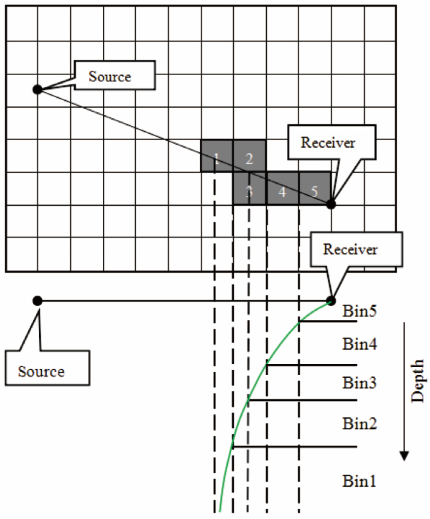
Due to the fact that the projection of the PS-wave conversion point on the horizontal surface gradually approaches the receiver point as the depth decreases, the conversion points at different depths will have different spatial coordinates. Seismic data are typically processed using a gridding method, and thus, we have also employed a gridding method for conversion point calculations. As shown in Figure 3, the projection of the conversion points at various depths falls within different imaging grids. Thus, for a given seismic trace, the imaging grid CCPi corresponding to the conversion point at depth z can be expressed as [47]:
C C P i = ( x ( r , s , g , v P R M S , z ) , y ( r , s , g , v P R M S , z ) )
here, vPRMS represents the root-mean-square P-wave velocity; x represents the horizontal coordinate of the conversion point, and y represents the vertical coordinate of the conversion point.
Calculating the conversion points using Equation (3) and then utilizing ray theory to calculate the corresponding travel time t for the seismic trace and complete data sorting, we have the following equation:
t = r s 2 + z 2 v P R M S + g r g 2 + z 2 v P R M S
here, rs and rg, respectively, represent the horizontal distances between the conversion point at depth z and the source and the receiver.

3. Numerical Examples

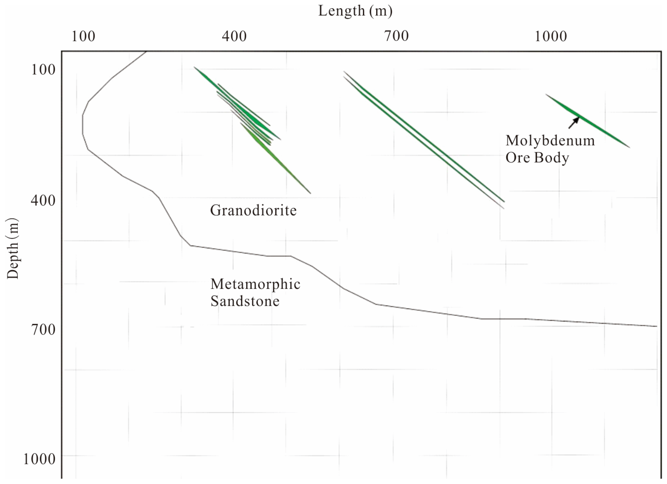
Based on the structural–geological characteristics of metal ore deposits, a simple seismic geological model for a molybdenum deposit is established, as shown in Figure 4. Considering significant physical property differences between the ore body and surrounding rocks and potentially smaller differences between the mineralized alteration zone and host rocks [30], the physical parameters for this 2D molybdenum deposit are defined in Table 1. The model extends 1200 m in length and is buried at a depth of 1000 m, in which the ore body is characterized by a narrow and inclined distribution within a granodiorite body. The seismic acquisition scheme includes a source interval of 30 m, with a receiver spacing of 5 m, utilizing a dual-source shooting method, with the smallest offset at 0 m and the largest offset at 1450 m, involving a total of 47 shots. To mitigate the influence of surface waves, absorbing boundary conditions are employed during forward modeling, using a 50 Hz Ricker wavelet for elastic wave finite difference simulation, as illustrated by a typical shot gather recordin Figure 5. From the figure, it can be observed that the steep ore body and irregular geological interfaces lead to complex interactions among direct waves, reflected waves, and scattered waves, resulting in a highly intricate seismic wavefield on the X– and Z– components, making it challenging to identify hyperbolic reflection waves in the shot gather. Furthermore, the wave-form leakage phenomena can also be observed, as indicated by red arrows, by comparing Figure 5a,b.
After applying the wavefield separation method based on the affine coordinate system to the synthetic data [48], pre-stack time migration imaging was performed separately for the X and Z components, resulting in the imaging shown in Figure 6. It is apparent that both PP-waves and PS-waves have achieved good imaging of inclined interfaces and ore bodies. However, it should be noted that at the location indicated by the red arrow in Figure 6, because of the extremely steep interface, reflection signals from this lithological interface are only obtained from the source–receiver pairs in the x: 0~200 m, resulting in poor illumination and, consequently, causing discontinuities in the imaging. Furthermore, in the comparison between the PP-wave and PS-wave migrated sections, it is observed that due to its longer travel time, the PS-wave events have a steeper dip compared to the PP-wave, making the PS-wave more effective in describing fine structures, as indicated by the green arrow. Further analysis of the stacked sections revealed that when imaging the multi-layer inclined ore body on the leftmost side (the red box), the seismic resolution of the 1/4 wavelength prevents accurate identification of the internal features for thin ore layers, only delineating the ore deposit. However, when the spacing between ore bodies exceeds 1/4 wavelength, the internal features of the ore bodies are clearly depicted, as observed in the double-layer inclined ore body in the middle of the model (green box). Additionally, due to the incomplete separation of the P- and S-waves, and in order to accurately depict steep structures during migration, we utilized a large image dip, thus introducing imaging noise, as illustrated by the blue arrow in Figure 6.
The imaging of the synthetic data has shown that the multi-component seismic technique exhibits good performance in describing the distribution and internal structures of steep geological formations and ore bodies. Moreover, the longer travel time of PS-waves results in a clearer depiction of small-scale structures compared to PP-waves, highlighting the advantages of multi-component seismic technology in the exploration of metal ores.

4. A Case Study of 2D3C Seismic Exploration for Copper–Molybdenum Deposits in Inner Mongolia

4.1. Geological Overview

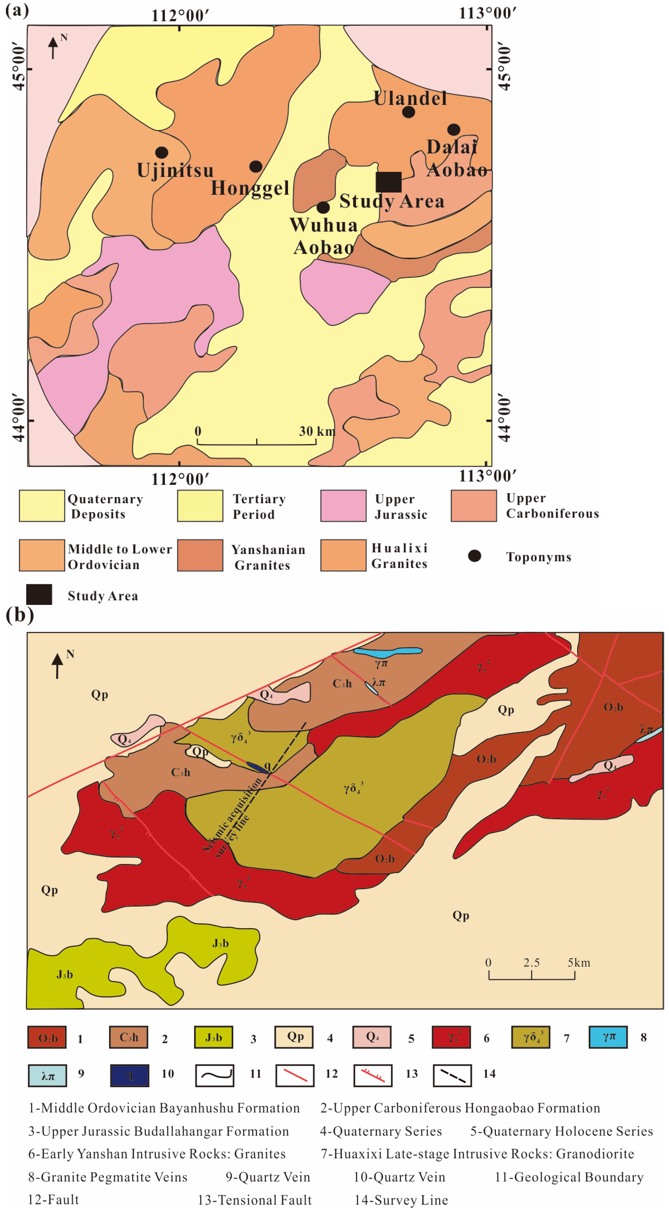
The 2D3C seismic experimental area of the Inner Mongolia copper–molybdenum mine is located in the Dalaimiao-Wurinitu area north of Erenhot-Sunit Zuoqi in Inner Mongolia, China. The regional geological background is shown in Figure 7a [49,50]. The structural position belongs to the early Paleozoic continental margin accretionary belt on the southeastern continental margin of the Siberian Plate. The southern wing of the Dalaimiao anticline is the main structural feature in the mining area with non-obvious fold structures, and the predominant structural trend is northeast-trending faulting, with northwest-trending faults as secondary structures [51], as shown in Figure 7b.
The exposed stratigraphic sequence within the area includes the Middle Ordovician (O2b), Upper Carboniferous (C3h), Upper Jurassic (J3b), and Quaternary (Q) formations. Among them, the Upper Carboniferous Hong’aobao Formation clastic rock section (C3h) is the most widely exposed formation in the area. The upper part is mainly composed of metamorphic arkose, tuffaceous arkose, tuffaceous feldspathic sandstone, and andesite, while the lower part is dominated by metamorphic arkose. Quaternary gravel layers (Q) are primarily distributed in the northern part of the working area. In addition, magmatic rocks are widely distributed within the experimental area, including exposed Permian granodiorite (γδ43) and Jurassic biotite granite (γ52) [51].
The mineralized rock mass in this area is the Permian granodiorite, in which quartz veins (q) are well developed and often contain molybdenum mineralization. Therefore, the molybdenum-bearing quartz veins constitute the ore body. The ore body is mainly located within a nearly north-west oriented extensional fault zone, crossing the diorite veins, indicating a relatively late mineralization process. The surrounding rock of the ore body is predominantly composed of granodiorite, with local occurrences of metamorphic arkose [52]. Density and velocity tests were conducted on the collected rock and ore samples to obtain the average P-wave and S-wave velocity and density data for different rock and ore types, with specific data listed in Table 2 [53].

4.2. Data Analysis and Processing

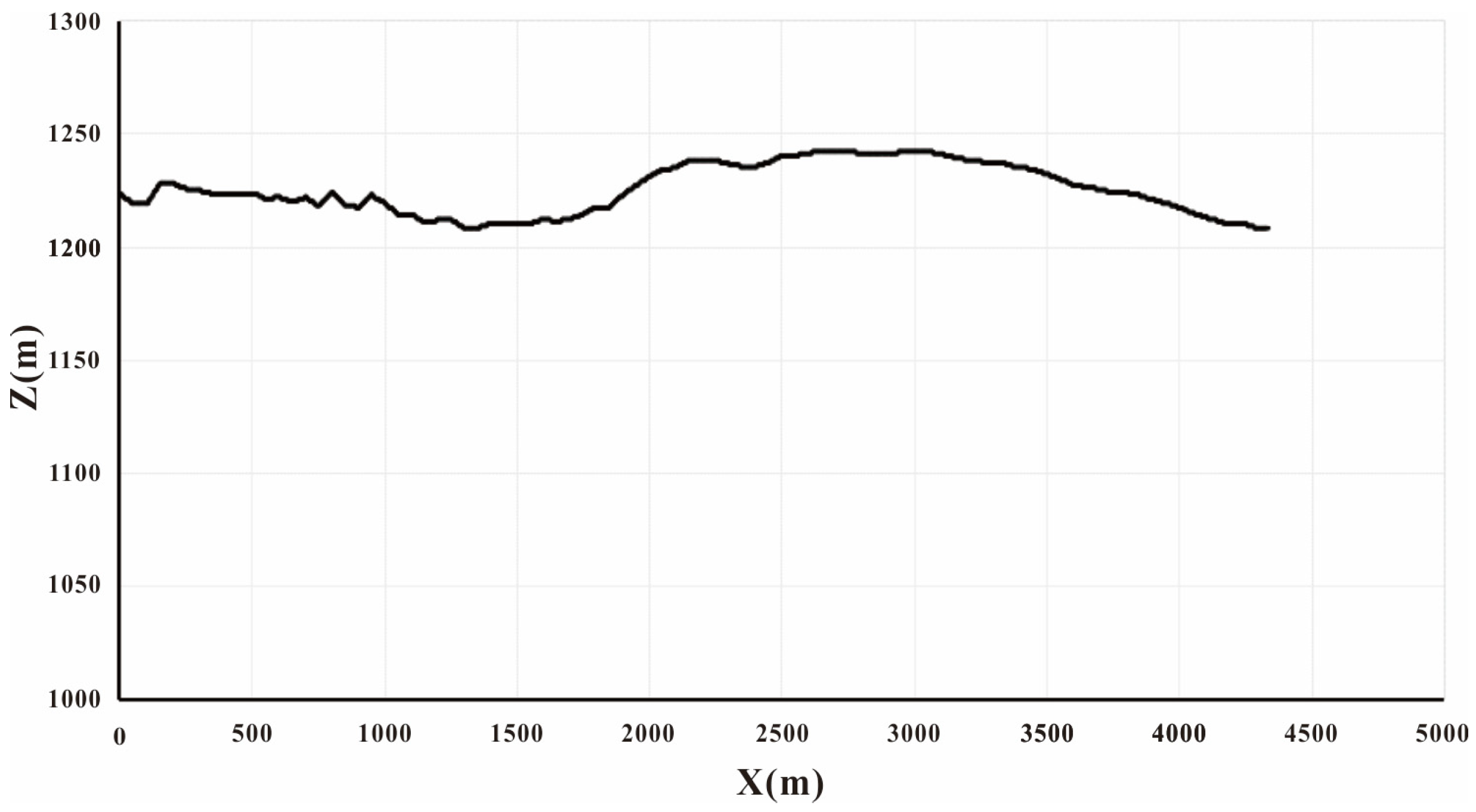
The data acquisition in this study utilized a multi-fold coverage observation system that combined single-sided and central excitation. The parameters included a source spacing of 30 m, receiver spacing of 15 m, minimum offset of 30 m, maximum offset of 3615 m, 60-fold coverage, and 240 channels for receivers. The acquisition duration was 7 s with a sampling interval of 0.5 ms. The excitation method employed an explosive source well with a depth of 10 m and a charge of 5 kg. The elevation within the working area ranged from 1200 to 1250 m, and the variation in elevation along the survey lines is depicted in Figure 8. From the figure, it can be observed that the elevation fluctuation along the survey lines is relatively gentle, and the maximum elevation difference is approximately 30 m.
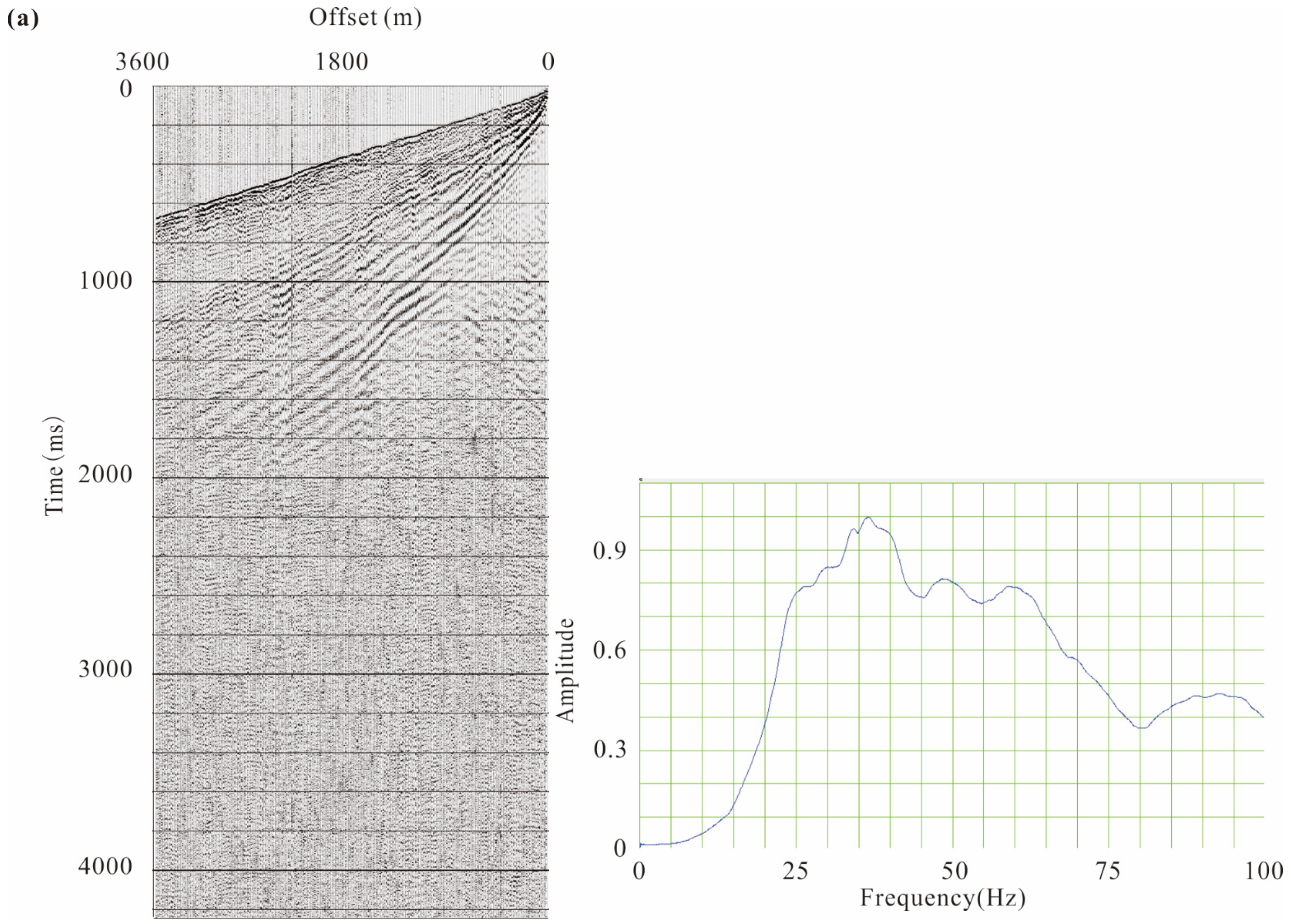
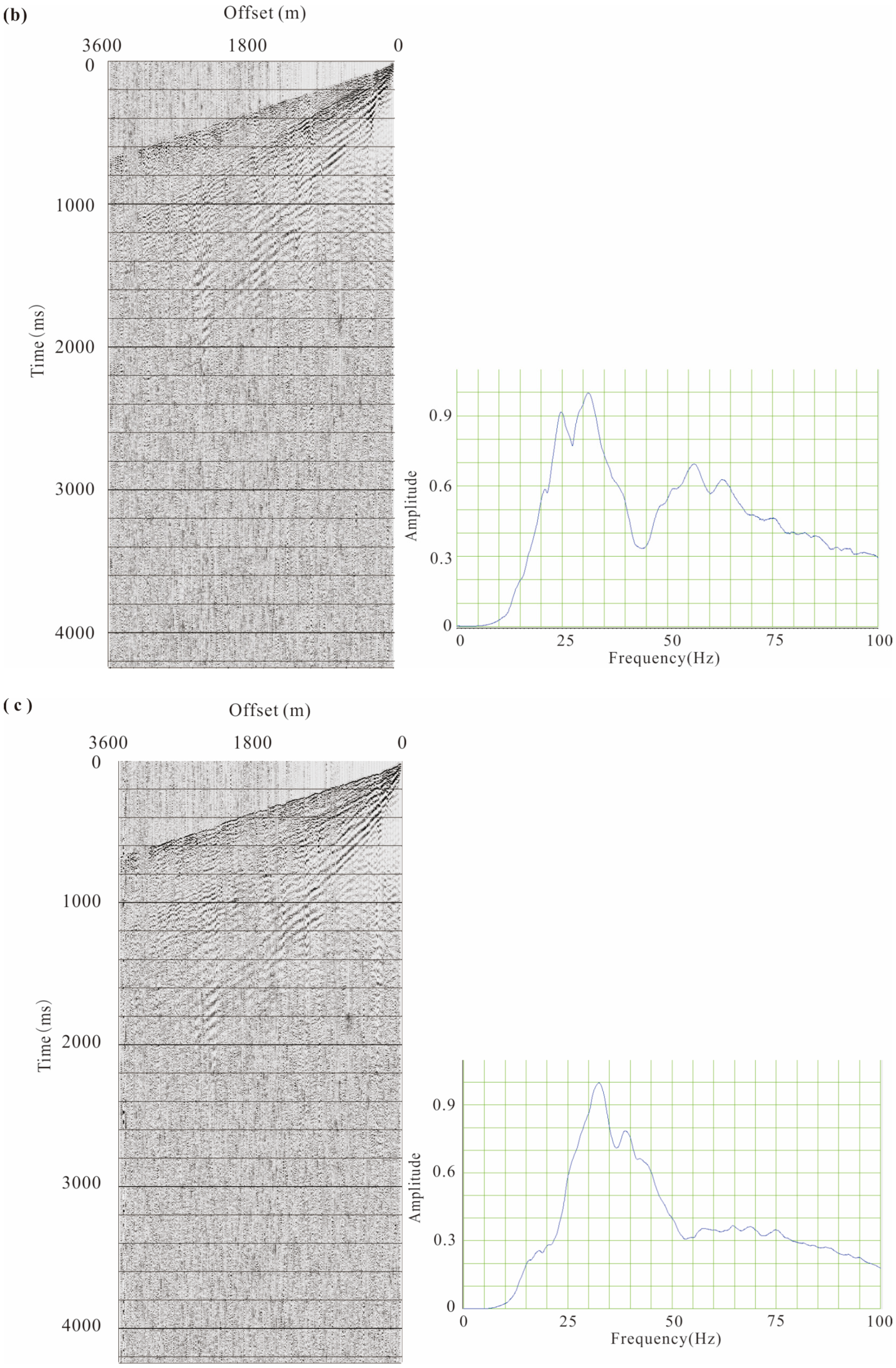
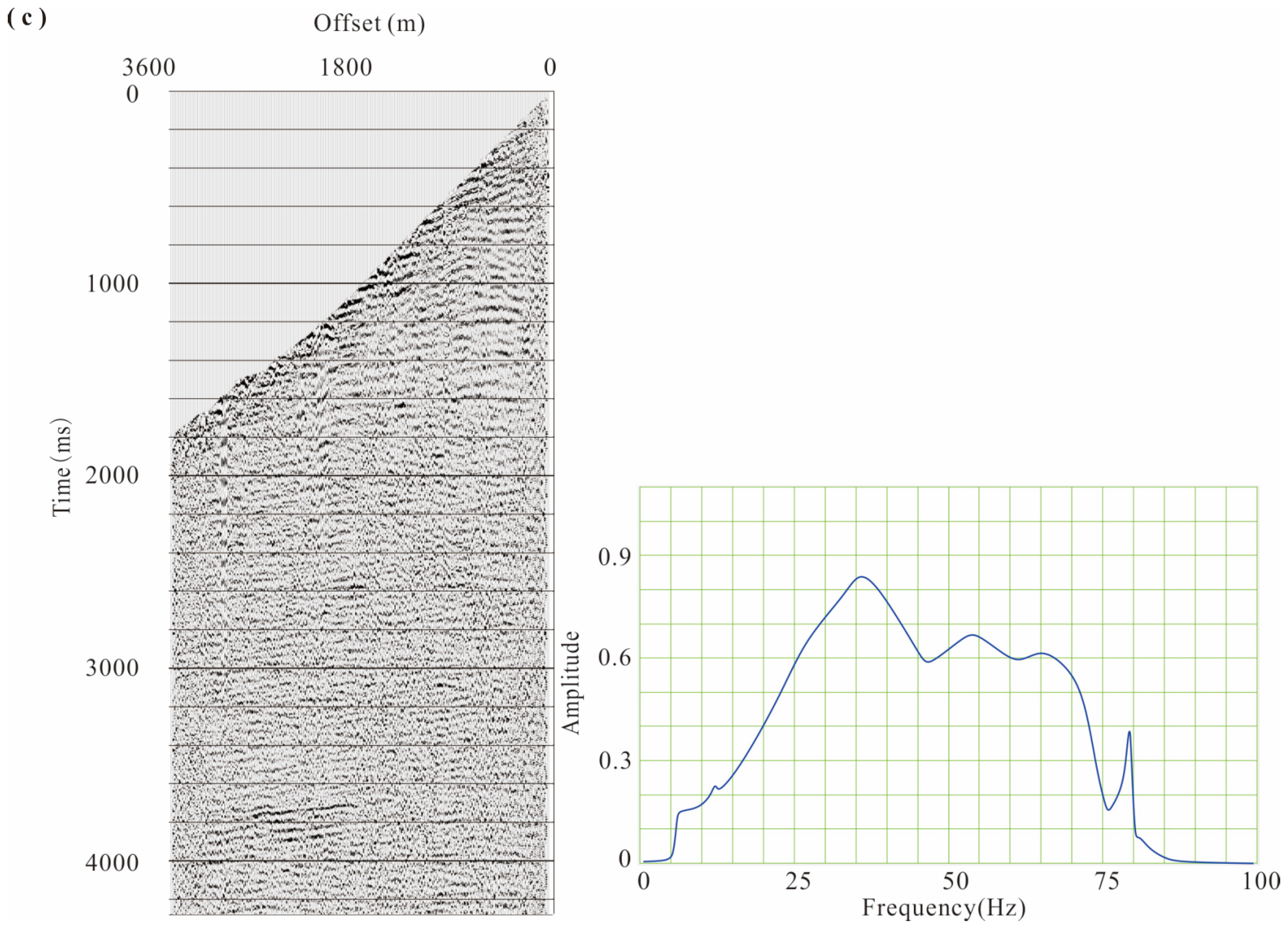
The 2D3C shot gathers and frequency spectrums are shown in Figure 9. From the figure, it can be observed that due to the influence of complex seismic geological conditions, the shot gathers mainly exhibit significant direct waves, refracted waves, surface waves, and scattered waves. Therefore, data processing presents a challenge due to the low signal-to-noise ratio, which makes it difficult to observe effective reflection signals. Moreover, the frequency spectra show that the dominant frequency for the X- and Y-components is 33 Hz, while the dominant frequency for the Z-component is 37 Hz, with minimal differences in dominant frequencies. Additionally, despite the majority of the surface in the area being covered by Quaternary deposits, there are still exposures of granite and metamorphic rocks, leading to complex near-surface seismic conditions and a relatively high near-surface velocity. The near-surface P-wave velocity is approximately 5500 m/s, and the S-wave velocity is approximately 3200 m/s.
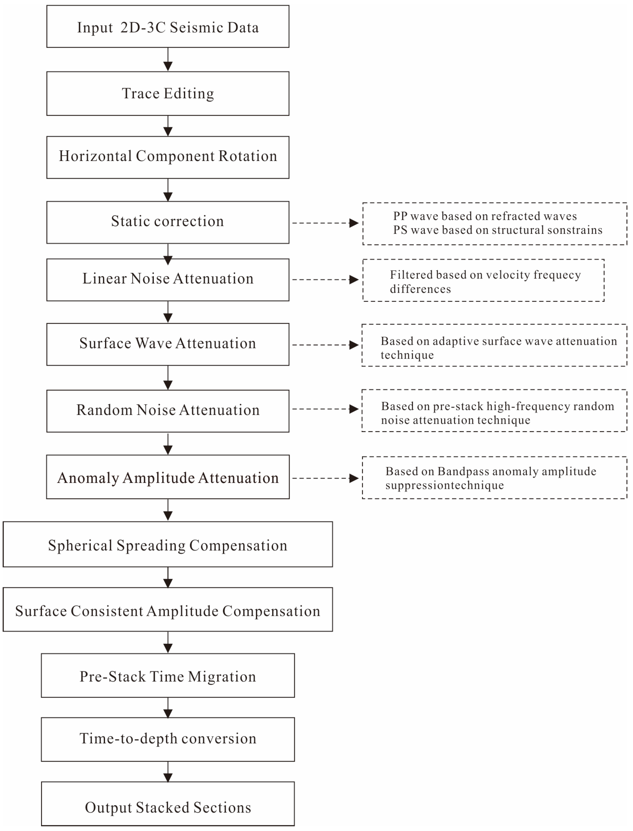
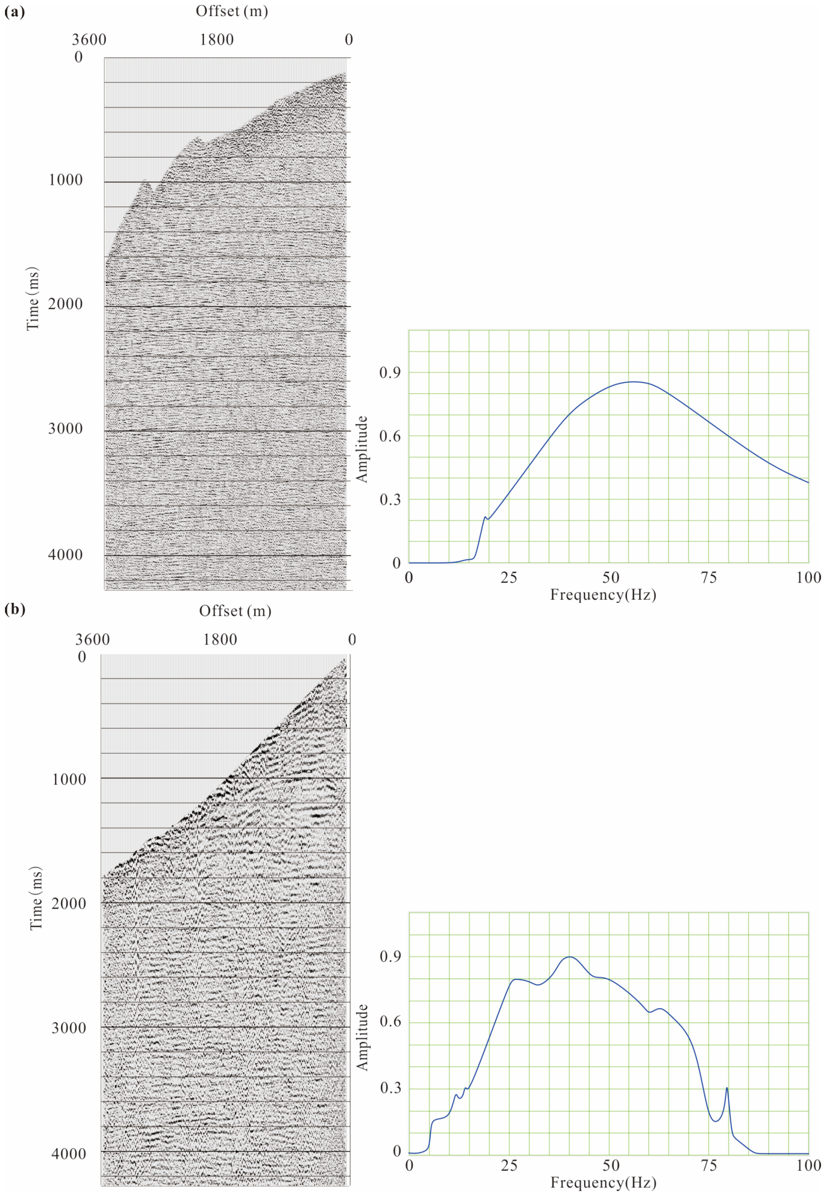
Based on the data characteristics of the study area, a technical workflow for the processing of multi-component seismic was constructed, as shown in Figure 10. Our focus was reflected on attenuating linear noise, surface waves, and random noise to improve the signal-to-noise ratio of the data. Moreover, amplitude compensation was employed to equalize the energy at different spatial positions. The preprocessed seismic records are depicted in Figure 11. From the figure, it can be observed that after denoising and amplitude compensation, previously unobservable reflection and scattering signals are highlighted, and the bandwidth is significantly increased. Furthermore, in terms of static correction, we applied the refraction static correction method for the PP-wave and performed the structural constraint method for the PS-wave.

4.3. Imaging

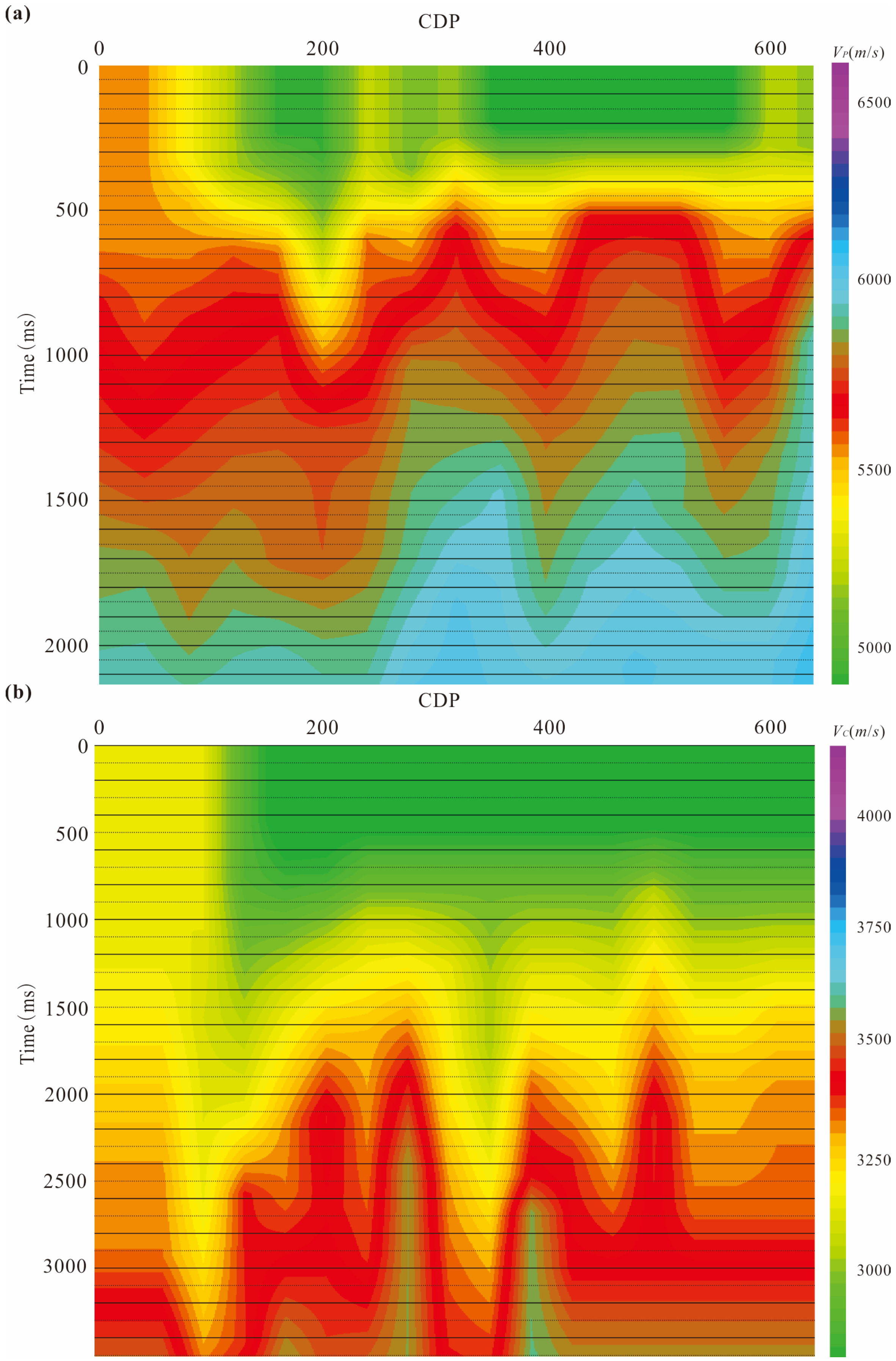
Through pre-stack time migration, we obtained migrated sections of PP- and PS-waves, as well as the corresponding root-mean-square velocity field, as shown in Figure 12 and Figure 13. From the figures, it is evident that when faced with low signal-to-noise ratio and complex seismic geological conditions, we have achieved good imaging results, effectively characterizing the subsurface structures. Observing the migrated sections of PP- and PS-waves, we can see that the underground structures are predominantly characterized by high-angle steep formations, and the migrated sections display numerous small-scale discontinuous events. Furthermore, the main wave characteristics of the PS-wave migrated section correspond well with the PP-wave. In Figure 13, lateral variations are observed in the root-mean-square velocity field, reflecting the complexity of the structure in this area.
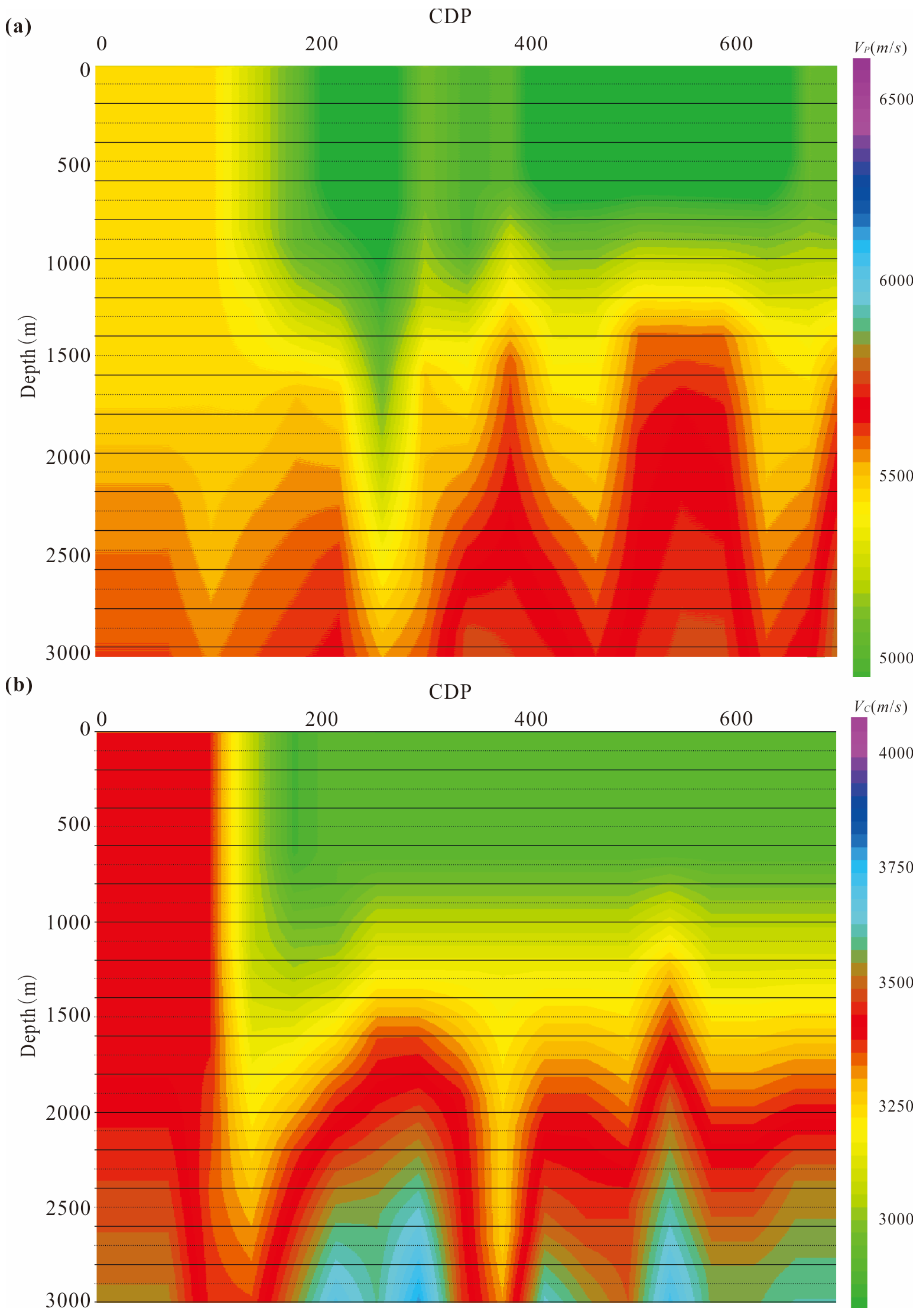
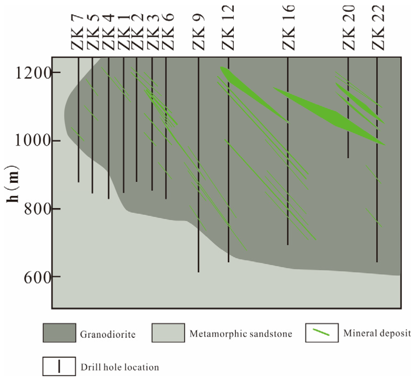
To facilitate the interpretation, we transformed the time-domain migrated sections into the depth domain through the time-to-depth conversion. Furthermore, we converted the root-mean-square velocity from the time domain to the depth domain. The results are illustrated in Figure 14 and Figure 15. From the depth-domain migrated sections in Figure 14, we can observe that the main wave characteristics between PP- and PS-waves become more pronounced, as indicated by the red arrows. Affected by the low signal-to-noise ratio, the PS-wave imaging quality is not as high as the PP-wave. However, the structural information provided by PS-waves is more comprehensive, complementing the areas that cannot be imaged by PP-waves, as indicated by the red box in the figure. From the depth-domain interval velocity in Figure 15, it can be observed that PP- and PS-waves exhibit similar structures. Furthermore, based on previous studies [51,52], we conducted a comparison between our imaging results of PP and PS-waves and the corresponding geological cross-section (Figure 16). Our findings demonstrate that our imaging sections effectively portray the structural characteristics of the mineral deposit, confirming their accuracy and high imaging quality. Additionally, comparing the velocity field depicted in Figure 15 with the geological cross-section, we observed that the overall morphological features of the velocity field are consistent with the background structures. Unfortunately, the geological cross-section covers a relatively short span, approximately corresponding to common depth point (CDP) positions 1–350, limiting further comparison beyond this range. Nevertheless, taking into account the directional features of the mineral deposit and the geological structural background, the imaging results from CDP positions 350–700 remain accurate and exhibit commendable imaging quality.
Furthermore, in the comparison of migrated sections between PP- and PS-waves, we found that although PS-wave imaging is generally not as good as PP-wave imaging, the imaging of PS-waves within the red box in Figure 14 is superior to that of PP-waves, and the distribution of energy in the migrated section is relatively homogeneous. As migrated sections correspond to wave impedance interfaces, the greater the difference in wave impedance, the stronger the reflection energy. Therefore, based on the physical properties of rocks in Table 2, we calculated the wave impedances of P-waves and S-waves, as shown in Table 3 and Table 4. From the tables, it is evident that there is significant fluctuation in the wave impedance contrast of P-waves, with a notable difference in wave impedance between the ore body and surrounding rock, which is advantageous for identifying mineralization locations. However, it may also lead to weaker reflection signals between certain interfaces, resulting in poor imaging. In contrast, the fluctuation in wave impedance contrast between different rocks for PS-waves is relatively small, leading to minor differences in the energy of the reflection signals, which is beneficial for accurately delineating various geological structures. This overcomes the disadvantage of weak wave impedance contrast in PP-waves and holds significant implications for interpreting the overall structure of metallic deposits.
Therefore, through the study of the multi-component seismic data of the copper–molybdenum ore, we conclude that the imaging results of PP- and PS-waves complement each other, thus validating the effectiveness of multi-component seismic techniques in metallic mineral exploration. In comparison to traditional P-wave processing methods, multi-component seismic techniques offer more comprehensive information, compensating for the weak impedance contrast of crystalline rocks.

5. Discussion

Through synthetic data and field data testing, the study demonstrates that multi-component seismic techniques can better characterize subsurface structures when faced with complex surface environments and geological formations. Due to the different impedance contrasts of P- and S-waves, the resulting seismic responses are various. Therefore, we utilize PS-wave imaging results to complement areas where PP-waves cannot image, addressing the problem of weak impedance contrast for crystalline rock regions. Therefore, in mineral exploration, multi-component seismic techniques exhibit significant advantages in structural description compared to traditional P-waves.
High-quality imaging relies on the cooperation of various processing steps. Metal deposits, limited in scale, present challenges such as complex structures, low signal-to-noise ratio, discontinuous reflections, and strong scattering. Therefore, it is necessary to fully utilize noise suppression techniques to highlight effective signals. Since the seismic wavefield is a vector field, it is essential for multi-component seismic exploration to maintain the polarization characteristics of waves and to construct a rational processing workflow by utilizing vector noise suppression techniques as much as possible. Additionally, steep and small-scale metal deposits result in developed scattered waves, leading to interference between reflected waves and scattered waves. Numerous algorithms for separating reflected waves from scattered waves have been developed in the oil and gas exploration field. Consequently, we may consider first separating reflected waves from scattered waves and then conducting imaging with multi-component seismic data.
The study primarily focuses on the effective role of multi-component seismic techniques in characterizing structures for mineral exploration. However, it is important to note that multi-component seismic data contains abundant information about the subsurface. Therefore, future research can be directed towards the joint inversion of PP and PS-waves to further obtain the elastic parameters of the subsurface, providing additional assistance to mineral exploration.

Author Contributions

Conceptualization, Y.L. and Y.W.; methodology, Y.W. and Y.L.; formal analysis, Y.G., G.Y. and M.X.; data curation, Y.G. and M.X.; investigation, Y.L., Y.W., G.Y. and Y.Z.; writing—review and editing, Y.L., Y.W. and Y.Z.; supervision, Y.W. All authors have read and agreed to the published version of the manuscript.

Funding

The work presented in this paper is supported by the National Natural Science Foundation of China (Nos. 42150201, 62127815).

Data Availability Statement

The data presented in this study are available on request from the corresponding author. The data are not publicly available because the company provided the data involving the commercial interests.

Acknowledgments

We would like to thank all the editors and anonymous reviewers for their comments and helpful suggestions. We also acknowledge the valuable suggestions and assistance provided by Shijun Chen from the Beijing Institute of Multi-component Seismic Research and Wenlu Wang from Anhui University for this study.

Conflicts of Interest

The authors declare no conflicts of interest.

References

  1. Chen, Y.; Mao, J. Increase in Technological Investment for Mineral Exploration and Development in China. Sci. Technol. Ind. China 2022, 8, 6–10. (In Chinese) [Google Scholar] [CrossRef]
  2. Dong, S.; Li, T.; Chen, X.; Gao, R.; Lü, Q.; Shi, Y.; Huang, D.; Yang, J.; Wang, X.; Wei, W.; et al. SinoProbe revealed crustal structures, deep processes, and metallogenic background within China continent. Earth Sci. Front. 2014, 21, 201–225. (In Chinese) [Google Scholar]
  3. Teng, J. Strengthening geophysical exploration and exploitation of metallic minerals in the second deep space of the crustal interior. Geol. Bull. China 2006, 25, 767–771. (In Chinese) [Google Scholar]
  4. Teng, J.; Liu, J.; Liu, C.; Yao, J.; Han, L.; Zhang, Y. Prospecting for Metal Ore Deposits in Second Deep Space of Crustal Interior, the Building of Strategy Reserve Base of Northeast China. J. Jilin Univ. (Earth Sci. Ed.) 2007, 37, 633–651. [Google Scholar]
  5. Liang, G.; Cai, X.; Zhang, B.; Xu, X. Application of shallow seismic exploration methods in deep prediction of gold mines. Geol. Explor. 2001, 37, 29–33. (In Chinese) [Google Scholar]
  6. Eaton, D.W.; Milkereit, B.; Salisbury, M. Seismic methods for deep mineral exploration: Mature technologies adapted to new targets. Lead. Edge 2003, 22, 580–585. [Google Scholar] [CrossRef]
  7. Lü, Q.; Hou, Z.; Shi, D.; Zhao, J.; Xu, M.; Chai, M. Seismic reflection results of the Shizishan metal mine in Tongling and its significance for regional exploration. Miner. Depos. 2004, 23, 390–398. (In Chinese) [Google Scholar]
  8. Gou, L.; Liu, X.; Lei, P.; Liu, S. Review of seismic survey in mining exploration: Theory and reflection seismic method. Prog. Explor. Geophys. 2007, 30, 16–24. (In Chinese) [Google Scholar]
  9. Xu, M.; Gao, J. Seismic Exploration for Metallic Deposits; Geological Publishing House: Beijing, China, 2009; pp. 1–263. [Google Scholar]
  10. Schmidt, G. Results of underground seismic reflection investigations in siderite district of the Siegerland. Geophys. Prospect. 1959, 7, 287–290. [Google Scholar] [CrossRef]
  11. Milkereit, B.; Eaton, D.; Wu, J.; Perron, G.; Berrer, E.; Morrison, G. Seismic imaging of massive sulphide deposits: Part II. Reflection seismic profiling. Econ. Geol. 1996, 91, 829–834. [Google Scholar] [CrossRef]
  12. Milkereit, B.; Berrer, E.K.; King, A.R.; Watts, A.H.; Roberts, B.; Erick, A.; Eaton, D.W. Development of 3D seismic exploration technology for deep nickel-copper deposits-A case history from the Sudbury basin, Canada. Geophysics 2000, 65, 1890–1899. [Google Scholar] [CrossRef]
  13. Malehmir, A.; Bellefleur, G. 3D seismic reflection imaging of volcanic-hosted massive sulfide deposits: Insights from reprocessing Halfimile Lake data, New Brunswick, Canada. Geophysics 2009, 74, B209–B219. [Google Scholar] [CrossRef]
  14. Cheraghi, S.; Malehmir, A.; Bellefleur, G. 3D imaging challenges in steeply dipping mining environment: New lights on acquisition geometry and processing from the Brunswick no. 6 seismic data, Canada. Geophysics 2012, 77, WC109–WC122. [Google Scholar] [CrossRef]
  15. Drummond, B.J.; Goleby, B.R.; Goncharov, A.G.; Wyborn, L.A.I.; Collins, C.D.N.; MacCreadyb, T. Crustal-scale struc tures in the Proterozoic Mount Isa Inlier of north Australia: Their seismic response and influence on mineralization. Tectonophysics 1998, 288, 43–56. [Google Scholar] [CrossRef]
  16. Goleby, B.R.; Korsch, R.J.; Fomin, T.; Bell, B.; Nicoll, M.G.; Drummond, B.J.; Owen, A.J. Preliminary 3-D geological model of the Kalgoorlie region, Yilgarn Craton, Western Australia, based on deep seismic reflection and potential-field data. Aust. J. Earth Sci. 2002, 49, 917–933. [Google Scholar] [CrossRef]
  17. Pretorius, C.C.; Muller, M.R.; Larroque, M.; Wilkins, C. A review of 16 years of hard rock seismics on the Kaapvaal Craton. In Hardrock Seismic Exploration; Eaton, D.W., Milkereit, B., Salisbury, M.H., Eds.; SEG: Houston, TX, USA, 2003; pp. 247–268. [Google Scholar] [CrossRef]
  18. Kukkonen, I.T.; Heinonen, S.; Heikkinen, P.; Sorjonen-Ward, P. Delineating ophiolite-derived host rocks of massive sulfide Cu-Co-Zn deposits with 2D high-resolution seismic reflection data in Outokumpu, Finland. Geophysics 2012, 77, WC213–WC222. [Google Scholar] [CrossRef]
  19. Malehmir, A.; Durrheim, R.; Bellefleur, G.; Urosevic, M.; Juhlin, C.; White, J.D.; Milkereit, B.; Campbell, G. Seismic methods in mineral exploration and mine planning: A general overview of past and present case histories and a look into the future. Geophysics 2012, 77, WC173–WC190. [Google Scholar] [CrossRef]
  20. Bancroft, J.C.; Geigert, H.D.; Margrave, G.F. The equivalent offset method of prestack time migration. Geophysics 1998, 63, 2042–2053. [Google Scholar] [CrossRef]
  21. Wang, Y.; Wang, W.; Yin, J. A modified EOM method for PS wave mi gration. Explor. Geophys. 2012, 43, 156–161. [Google Scholar] [CrossRef]
  22. Fleury, C.; Vasconcelos, I. Imaging condition for nonlinear scattering-based imaging: Estimate of power loss in scattering. Geophysics 2012, 77, S1–S18. [Google Scholar] [CrossRef]
  23. Fang, X.; Fehler, C.; Zhu, Z.; Zheng, Y.; Burns, D.R. Reservoir fracture characterization from seismic scattered waves. Geophys. J. Int. 2014, 196, 481–492. [Google Scholar] [CrossRef]
  24. Yan, T.; Liu, Y. Fracture detection using scattered waves in the angle domain. Geophysics 2021, 86, S257–S269. [Google Scholar] [CrossRef]
  25. Li, Z.; Yin, J.; Wang, Y. Application of seismic scattered wave simulation imaging in metal ore exploration. Geol. Explor. 2009, 45, 80–84. (In Chinese) [Google Scholar]
  26. Malcolm, A.E.; Hoop, M.V.; Ursin, B. Recursive imaging with multiply scattered waves using partial image regularization: A North Sea case study. Geophysics 2011, 76, B33–B42. [Google Scholar] [CrossRef]
  27. Hu, R.Z.; Wen, H.; Ye, L.; Chen, W.; Xia, Y.; Fan, H.; Huang, Y.; Zhu, J.; Fu, S. Metallogeny of critical metals in the Southwestern Yangtze Block. Chin. Sci. Bull. 2020, 65, 3700–3714. (In Chinese) [Google Scholar] [CrossRef]
  28. XU, J.; Yang, J.; Wang, Y.; Huang, J.; Guo, W.; Yang, Y. Full-wavefield migration method by amplitude-preserving inverse scattering imaging condition. Oil Geophys. Prospect. 2024, 59, 98–109. (In Chinese) [Google Scholar]
  29. Lu, L.; Vincent, E.; Xu, J. Imaging diffractors using wave-equation migration. Geophysics 2016, 81, S459–S468. [Google Scholar] [CrossRef]
  30. Wang, Z.; Lü, Q. Separation and Imaging of Seismic Diffractions on Metal Deposit: Two Cases in Luzong Deposit Concentration Area and Qinhang Metallogenic Belt. Acta Geosci. Sin. 2017, 38, 79–82. (In Chinese) [Google Scholar]
  31. Li, W.; Liu, Y.; Chen, R.; Xu, S.; Tan, Y.; He, Y.; Hua, X.; Jia, J. Removing the complex nearsurface scattered wave via an angle-domain vector resolution method. Geophys. Prospect. Pet. 2021, 60, 565–573. (In Chinese) [Google Scholar]
  32. Yang, J.; Sun, J.; Huang, J.; Li, Z.; Qin, S.; Yu, Y. Intelligent diffractions imaging method for fault-karst reservoir. Jourmal China Univ. Pet. (Ed. Nat. Sci.) 2024, 48, 67–73. [Google Scholar]
  33. Bellefleur, G.; Müller, C.; Snyder, D.; Matthews, L. Downhole seismic imaging of a massive sulfide orebody with mode-converted waves, Halfmile lake, New Brunswick, Canada. Geophysics 2004, 69, 318–329. [Google Scholar] [CrossRef]
  34. Snyder, D.B.; Cary, P.; Salisbury, M. 2D-3C high-resolution seismic data from the Abitibi Greenstone Belt, Canada. Tectonophysics 2009, 472, 226–237. [Google Scholar] [CrossRef]
  35. Malinowski, M.; White, D. Converted wave seismic imaging in the Flin Flon mining camp, Canada. J. Appl. Geophys. 2011, 75, 719–730. [Google Scholar] [CrossRef]
  36. Malehmir, A.; Wang, S.; Lamminen, J.; Brodic, B.; Bastani, M.; Vaittinen, K.; Juhlin, C.; Place, J. Delineating structures controlling sandstone-hosted base-metal deposits using high-resolution multicomponent seismic and radio-magnetotelluric methods: A case study from Northern Sweden. Geophys. Prospect. 2015, 63, 774–797. [Google Scholar] [CrossRef]
  37. Hu, R.Z.; Mao, J.W.; Hua, R. Intracontinental Metallogeny of South China Block; Science Press: Beijing, China, 2015. [Google Scholar]
  38. Tang, C.; Fu, L.; Xiao, F.; Du, Q. Review of progress in seismic exploration in metallic deposits. Rev. Geophys. Planet. Phys. 2022, 53, 187–203. [Google Scholar] [CrossRef]
  39. Zhou, J.; Xu, M.; Liu, J.; Gao, J.; Wang, X.; Zhang, B. Application of seismic reflection imaging in the Karatungk Cu–Ni deposit of Xinjiang. Geol. Explor. 2016, 52, 0910–0917. (In Chinese) [Google Scholar]
  40. Guo, W. Basic characteristics of the ore-forming conditions of major mineral resources in China. Sci. Bull. 1965, 3, 189–201. (In Chinese) [Google Scholar]
  41. Xu, M.; Chai, M.; Gao, J. Characteristics of seismic waves and physical properties of rocks and minerals in the Zhunsujihua mine of Inner Mongolia. Geol. Explor. 2015, 51, 1168–1174. (In Chinese) [Google Scholar]
  42. Khoshnavaz, M.J.; Bóna, A.; Hossain, M.S.; Urosevic, M.; Chambers, K. Diffractivity-another attribute for the interpretation of seismic data in hard rock environment, a case study. Interpretation 2016, 4, B23–B32. [Google Scholar] [CrossRef]
  43. Salisbury, M.H.; Harvey, C.W.; Matthews, L. The Acoustic Properties of Ores and Host Rocks in Hardrock Terrane//Hardrock Seismic Exploration. Soc. Econ. Geol. 2003, 10, 9–19. [Google Scholar]
  44. Qin, F.; Guo, Y.; Wang, M. Elastic wave Kirchhoff integral migration method. Chin. J. Geophys. 1988, 05, 577–587. (In Chinese) [Google Scholar]
  45. Yu, G.; Yao, C. The sorting method of CCP gathers and influencing factors in slanting interface. Coal Geol. Explor. 2007, 04, 65–69. (In Chinese) [Google Scholar]
  46. Yao, C.; Yu, G.; Cai, M. Angle-domain CDP and angle-domain CCP stacking. In 21st Annual Meeting of the Chinese Geophysical Society; Jilin University Press: Changchun, China, 2005; p. 1. (In Chinese) [Google Scholar]
  47. Li, Y.; Lu, J.; Wang, Y.; Zhang, Y.; Wu, Z. Converted PS-wave imaging based on offset vector tiles. Geophysics 2023, 88, S151–S161. [Google Scholar] [CrossRef]
  48. Lu, J.; Wang, Y.; Yao, C. Separating P- and S-waves in an affine coordinate system. J. Geophys. Eng. 2012, 9, 12–18. [Google Scholar] [CrossRef]
  49. Yang, Z.; Wang, J.; Liu, J.; Wang, S.; Wang, Q.; Kang, S.; Zhang, J.; Zhao, Y. Isotopic geochemical characteristics of the Wunugetu tungsten-molybdenum deposit in Sunitezuo Banner, Inner Mongolia. Geol. Rev. 2013, 27, 13–23. [Google Scholar]
  50. Kong, W.; Liu, C.; Deng, J.; Xu, L.; Zhao, G. Zircon U-Pb geochronology of quartz porphyry from the Wuhua’aobao molybdenum deposit in Erenhot area, Inner Mongolia, and its constraints on the molybdenum mineralization age. Miner. Depos. 2010, 29, 454–455. [Google Scholar]
  51. Xu, M.; Jiang, C.; Chai, M.; Gao, J. Three-component seismic experimental study of the Zhunsujihua Cu-Mo mine in Inner Mongolia. Prog. Geophys. 2016, 31, 1229–1236. (In Chinese) [Google Scholar] [CrossRef]
  52. Xu, M.; Zhou, J.; Chai, M.; Gao, J.; Liu, J.; Zhang, B. Seismic reflection detection in the Zhunsujihua porphyry molybdenum ore district and its periphery, Inner Mongolia. Geophys. Geochem. Explor. 2016, 40, 639–647. (In Chinese) [Google Scholar] [CrossRef]
  53. Yang, W.; Zhu, G.; Yang, Z.; Wang, H.; Xu, G.; Zhou, Y.; Yao, H.; Li, G. Three component seismic profiling at the Chinese Continent al Scientific Drilling site. Chin. J. Geophys. 2007, 50, 780–790. (In Chinese) [Google Scholar]
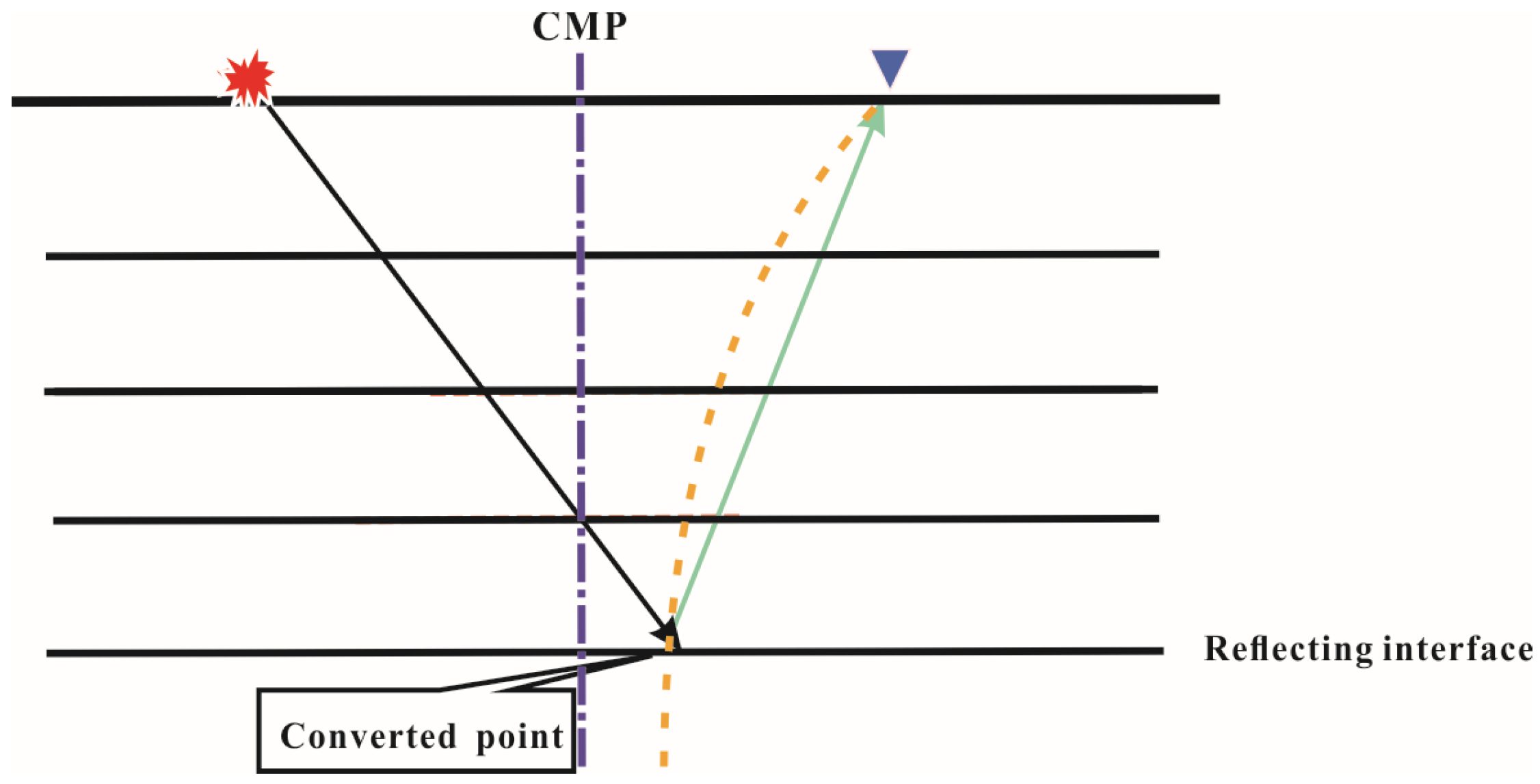
Figure 1. Schematic diagram of the PS-wave conversion point trajectory. The yellow dotted line is the conversion point trajectory at different depths, and the blue dotted line is the CMP. Lines with arrows are the PS-wave ray paths The red polygons represent the source, and the blue inverted triangles represent the receiver.
Minerals 14 00689 g001
Figure 2. Schematic illustration of PS-wave ray paths in inclined and horizontal interfaces. The solid black line arrows represent the PS ray paths in the inclined interface, while the dashed black line arrows denote the PS ray paths in the horizontal interface. h1 and h2 respectively denote the distances from conversion points C1 and C2 to their projections on the ground O.
Minerals 14 00689 g002
Figure 3. Calculation of PS-wave conversion point-based gridding method, where the green line represents the trajectory of the conversion points.
Minerals 14 00689 g003
Figure 4. Schematic diagram of a 2D multi-layer inclined copper mine model.
Minerals 14 00689 g004
Figure 5. Synthetic data 2D2C shot gathers. (a) Z-component and (b) X-component. The red arrows indicate wave leakage.
Minerals 14 00689 g005
Figure 6. Migrated section of PP- and PS-waves. (a) PP-wave and (b) PS-wave. Blue arrows indicate arcuate artifacts caused by migration noise. Red arrows highlight areas where steep structural dips result in weaker illumination. Green arrows demonstrate the richer PS-wave depiction of structural details compared to the PP-wave. Imaging results within the dashed red and green boxes, respectively, show the imaging for multi-layered formations with layer thicknesses less than and greater than 1/4 wavelength.
Minerals 14 00689 g006
Figure 7. Regional geological context and geological structural map of the study area. (a) Regional geological context (b) Geological structural map.
Minerals 14 00689 g007
Figure 8. Elevation variations along the survey line.
Minerals 14 00689 g008
Figure 9. The 2D3C shot gathers and its frequency spectrum. (a) Raw Z-component shot gather and its frequency spectrum. (b) Raw X-component shot gather and its frequency spectrum. (c) Raw Y-component shot gather and its frequency spectrum.
Minerals 14 00689 g009aMinerals 14 00689 g009b
Figure 10. Seismic processing workflow for 2D3C data in the Inner Mongolia copper–molybdenum mine.
Minerals 14 00689 g010
Figure 11. De-noised and amplitude-compensated 2D3C shot records and its frequency spectrum. (a) Z-component shot gather and its frequency spectrum, (b) X-component shot gather and its frequency spectrum, and (c) Y-component shot gather and its frequency spectrum.
Minerals 14 00689 g011aMinerals 14 00689 g011b
Figure 12. Migrated section of PP- and PS-waves (time domain). (a) PP-wave and (b) PS-wave.
Minerals 14 00689 g012
Figure 13. Root-mean-square velocity field of PP- and PS-waves (time domain). (a) PP-wave and (b) PS-wave.
Minerals 14 00689 g013
Figure 14. Migrated section of PP- and PS-waves. (time-depth conversion to depth domain). (a) PP-wave, and (b) PS-wave. The red arrows indicate that the primary wave characteristics between PP- and PS-waves become more pronounced. The red boxes highlight clearer structural delineation by PS-waves compared to PP-waves.
Minerals 14 00689 g014
Figure 15. Root-mean-square velocity field of PP- and PS-waves (time–depth conversion to depth domain). (a) PP-wave, and (b) PS-wave.
Minerals 14 00689 g015
Figure 16. Geological cross-section.
Minerals 14 00689 g016
Table 1. Model parameters.
Rock TypeP-Wave
Velocity (m/s)
S-Wave
Velocity (m/s)
Density
(g/cm3)
Metamorphic Sandstone558032502.8
Granodiorite527029702.74
Molybdenum Ore Body487926003.77
Table 2. Density and velocity of rock and mineral samples in the study area.
Rock TypesP-Wave
Velocity (m/s)
S-Wave
Velocity (m/s)
Density
(g/cm3)
Granodiorite5271.42973.72.7402
Diorite (Vein)5566.03189.02.9094
Mineralized granite diorite5576.43251.52.8003
Copper–molybdenum mineralized Granite diorite (ore)5297.52769.32.8467
Granodiorite4879.02600.03.7670
Table 3. Absolute values of wave impedance contrast for various rock types (P-wave).
Rock TypesGranodioriteDiorite (Vein)Metamorphic SandstoneMineralized
Granite Diorite
Copper–Molybdenum
Mineralized Granite Diorite (Ore)
Granodiorite174911716363935
Diorite (vein)57811133934
Mineralized granite diorite5352764
Copper–molybdenum mineralized granite diorite (ore)3299
Table 4. Absolute values of wave impedance contrast for various rock types (S-wave).
Rock TypesGranodioriteDiorite (Vein)Metamorphic SandstoneMineralized Granite DioriteCopper–Molybdenum
Mineralized Granite Diorite (Ore)
Granodiorite11309572651646
Diorite (vein)1721395516
Mineralized granite diorite1222682
Copper–molybdenum mineralized granite diorite (ore)1911
Disclaimer/Publisher’s Note: The statements, opinions and data contained in all publications are solely those of the individual author(s) and contributor(s) and not of MDPI and/or the editor(s). MDPI and/or the editor(s) disclaim responsibility for any injury to people or property resulting from any ideas, methods, instructions or products referred to in the content.