Article

The Effects of Wind Velocity on the Binding Properties of Ash, Bottom Ash, and Additives: A Wind Tunnel Study

by
Sandra Petković Papalazarou
1,*,
Jasmina Nešković
1,
Stevan Ćorluka
2,
Svetlana Polavder
1,
Aleksandar Mitrašinović
3,4 and
Pavle Stjepanović
1
1
Mining Institute, Batajnicki Put 2, 11080 Belgrade, Serbia
2
Institute for Materials Testing—IMS, 11000 Belgrade, Serbia
3
The Department of Materials Science and Engineering, University of Toronto, Toronto, ON M5S 3E4, Canada
4
Institute of Technical Sciences of the Serbian Academy of Sciences and Arts, 11000 Belgrade, Serbia
*
Author to whom correspondence should be addressed.
Minerals 2024, 14(8), 809; https://doi.org/10.3390/min14080809 (registering DOI)
Submission received: 21 June 2024 / Revised: 29 July 2024 / Accepted: 6 August 2024 / Published: 10 August 2024
(This article belongs to the Special Issue Geochemical Characteristics and Contamination Risk Assessment of Soil)

Abstract

:
The more economically viable and environmentally sustainable approach for treating the by-products of coal combustion from thermal power plants entails their collective disposal as opposed to individual disposal methods. This aligns with pertinent EU directives and domestic regulations, ensuring compliance with established standards while optimizing resource utilization and minimizing environmental impact. This study evaluated the resistance to wind erosion of the binding properties of a mixture (fly ash (FA), bottom ash (BA), and additives) using an indoor wind tunnel under simulated ambient conditions. Investigations of the mutual impact of ash, bottom ash, and additives (CaO and Ca(OH)2) with a certain percentage of water were carried out with eighteen samples. The samples consisted of the water at six addition rates 5, 8, 10, 15, 20, and 25% (w/w), and additive at three addition rates (1, 2, and 3% (w/w). Based on the obtained results, the optimal ratios of additives (3% (w/w)) and water (15% (w/w)) were determined. Prior to the wind tunnel experiments, and according to the different addition rates of additives and water, eight samples were prepared with different addition rates of ash. The mass concentrations of suspended particles (PM10) and total suspended particles (TSPs) in these samples were measured at three distinct wind velocities: 1 m/s, 3 m/s, and 5 m/s, respectively. The results indicate that the samples containing the optimal content of additives and water demonstrate a maximum increase in PM10 emission zero values of no more than 1.9 times. This finding can be considered satisfactory from the standpoint of environmental protection.

1. Introduction

Coal is a vital energy source that has been developing globally for centuries [1,2]. While coal demand is declining in the United States and may decrease in the European Union this year, global coal consumption still rose by 1.4 percent in 2023, reaching a record 8.5 billion metric tons. The capacity for coal power plants currently under development increased by 16 percent [3]. Because the marginal cost of maintaining coal energy is lower than that of exploiting and using renewable and sustainable energy resources, and current technological advances have lowered the production and operation costs of traditional fossil energy sources while increasing energy efficiency, coal will continue to be consumed for a long time [4]. This trend has also been reinforced by turbulent global political situations. The global energy crisis triggered by the Russia–Ukraine military conflict, which began in February 2022, compelled Europe to revert to a coal-based power generation and energy consumption structure [5].
One of the more important factors is surface coal mines, where coal is stored and used, both in Serbia and worldwide [6]. Countries such as China, Australia, the USA, and others have a large number of surface coal mines [7]. However, due to the characteristics of surface coal mines, a lot of coal dust is produced in the process of storing, transporting, processing, and using coal, which seriously reduces the atmospheric visibility [8]. Apart from coal dust, the biggest problems are FA and BA, which are produced in the process of burning coal in thermal power plants (TPPs). FA is a kind of powdered mineral residue resulting from the combustion of coal which is captured from fly gas, and BA is heavier and harder to carry out with fly gas. Depending on the coal type and source, the chemical composition of BA is mostly similar to FA, mainly composed of silica, alumina, iron, calcium, alkalis with smaller percentages of calcium, magnesium, sulfates, and in some cases also heavy metals, but with a greater content of unburned carbon [9,10,11]. In recent years, with the continuous development of thermal power, the emission of fly ash (FA) has increased rapidly. Meanwhile, the dust from ash yards has caused serious secondary pollution to the local ecological environment. Therefore, it is necessary to explore surface solidification technologies to prevent FA particles, which contain significant amounts of heavy metals, from dispersing into surrounding cities via wind. This dispersal can lead to severe haze and poses a great threat to the life and health of inhabitants.
The presence of heavy metals in ash can also lead to animal and plant poisoning and DNA damage, threatening the local ecological balance and necessitating the urgent stabilization of ash fields. Various dust control technologies have been employed in ash fields, including engineering methods, water sealing, chemical treatments, and vegetation cover [12]. However, the spray water sealing method, while easy to operate, requires frequent application and often yields unsatisfactory results due to the high porosity and poor water retention of FA [13].
Inhalation of polluted air containing high concentrations of particles or gasses such as SO2 is associated with short-term and long-term health problems, primarily affecting the respiratory and cardiovascular systems [14]. Approximately two million deaths worldwide annually are attributed to air pollution, primarily due to respiratory diseases and cancer [15]. The solidification/stabilization (S/S) method is a widely used treatment for the management and disposal of a broad range of contaminated wastes, particularly those contaminated with substances classified as hazardous. As a result, many different types of hazardous wastes are treated with different binding agents such as lime, cement, gypsum, slag, fly ash, or phosphate cements [16,17,18,19].
The disposal of ash, bottom ash, ash-and-bottom ash mixtures, formed at the combustion of coal, peat, and shale, is one of the main problems of the modern solid-fuel thermal power plants in Serbia. The existing system of disposing of combustion products at all landfills of thermal power plants in Serbia is the hydraulic transport of ash, bottom ash, and water mixtures with solid-to-liquid phase ratio S:L—1:10 (low-density hydromixture) and S:L—1:1 (high-density hydromixture). Adding additives to this mixture requires a reduction in the amount of water used for transport, and this significantly influences a reduction in the pollution of air, watercourses, surrounding land, and ecosystems and increases landfill stability [20].
In order to conduct a thorough evaluation of the interconnectedness and impact of FA, BA, and additives on enhancing the binding properties of the mixture, it was essential to identify the fundamental parameters required for the adoption of the most suitable disposal technology. To ascertain the optimal mass fraction of ash, bottom ash, additives, and water within the mixture, it was imperative to replicate landfill conditions as closely as possible in laboratory settings. A specialized wind tunnel, [21,22,23] has been constructed to replicate wind velocities ranging from 1 m/s to 5 m/s. This wind tunnel includes instrumentation for accurately measuring the concentration of PM10 and TSP, alongside capabilities for monitoring relative humidity and temperature. This development represents a novel approach in Serbian research, as the existing literature indicates no prior utilization of wind tunnels for studying solidified material at thermal power plant landfills in Serbia.
The principal objective of this investigation is to ascertain the influence exerted by combustion coal by-products originating from thermal power plants on the ambient air quality within close proximity to such facilities, where concentrations of PM10 often exceed prescribed legal air quality thresholds, with heightened prevalence observed during the winter season. This study is motivated by the imperative to discern an efficient technological framework for the responsible management of combustion by-products at all landfill sites with thermal power plants across Serbia.

2. Materials and Methods

2.1. Materials

The materials used in this research include fly ash and bottom ash procured from Thermal Power Plants in Kostolac, Serbia. As additives, calcium oxide (CaO) and calcium hydroxide (Ca(OH)2) from Kolubara Građevinar, Lazarevac, Serbia, were incorporated into the mixture.
For the preparation of the mixture, a comprehensive characterization of the fly ash and bottom ash samples was conducted. This included particle size analysis, the determination of bulk density in both loose and compacted states, and chemical composition analysis. These analyses were pivotal in selecting the optimal quantities of materials for subsequent testing in the wind tunnel. A detailed description of the methodologies employed in these analyses is provided below.

2.2. Methods

2.2.1. Characterization of the Initial FA and BA Samples

The particle size analysis of both fly ash and bottom ash was carried out using standard laboratory sieves. The sieving process was performed manually using Laboratory Test Sieves from Endecotts LTD, London, UK. The measurement of bulk density in both loose and compacted states was conducted in accordance with the Standard EN 1097-3:1998 [24]. The chemical composition of the samples was elucidated through silicate analysis, utilizing the Inductively Coupled Plasma-Optical Emission Spectroscopy (ICP-OES) technique. This analysis was performed using a Varian 710-ES axial ICP-OES spectrometer manufactured by Varian, located in Houten, The Netherlands [25].

2.2.2. Sample Preparation Protocol for Geo-Mechanical Testing

The program was designed to vary three factors: the quantity of water, the quantity and type of additive, and the aging duration post-test specimen’s formation. Three distinct groups of test specimens were subsequently created:
  • base (initial) test specimens containing only ash and water without additives,
  • test specimens with additive (ash + additive + water), and
  • test specimens with additive and bottom ash (ash + bottom ash + additive + water).
The authors established the percentage of added water within the range of 5 to 25%, relative to the dry weight of the sample, and the percentage of the additive ranging from 1 to 3%. Specifically, the test specimens were prepared using varying combinations of water and additives:
  • Water content (% w/w): 5%, 8%, 10%, 15%, 20%, 25%;
  • Additive content (% w/w): 1, 2, and 3.
Specifically,
Combinations included 5% water with additives at 1%, 2%, and 3%; 8% water with additives at 1%, 2%, and 3%; 10% water with additives at 1%, 2%, and 3%; 15% water with additives at 1%, 2%, and 3%; 20% water with additives at 1%, 2%, and 3%; and 25% water with additives at 1%, 2%, and 3%.
The aging period for the test specimens was set at 1, 7, and 28 days to evaluate their performance over time. All of the aforementioned factors are consistent with the relevant literature. The test specimens were prepared in the laboratory under consistent ambient conditions. The procedure for forming all the test specimens was identical and encompassed the following steps:
  • Measurement of the required quantities of water, fly ash, bottom ash, and additives according to the specifications outlined in Table 1.
  • Components were mixed and homogenized in a laboratory planetary mixer (manufactured by “Toni Technik”) for a duration of 5 min.
  • Addition of the specified amount of water to the mixture, followed by further stirring for an additional 5 min.
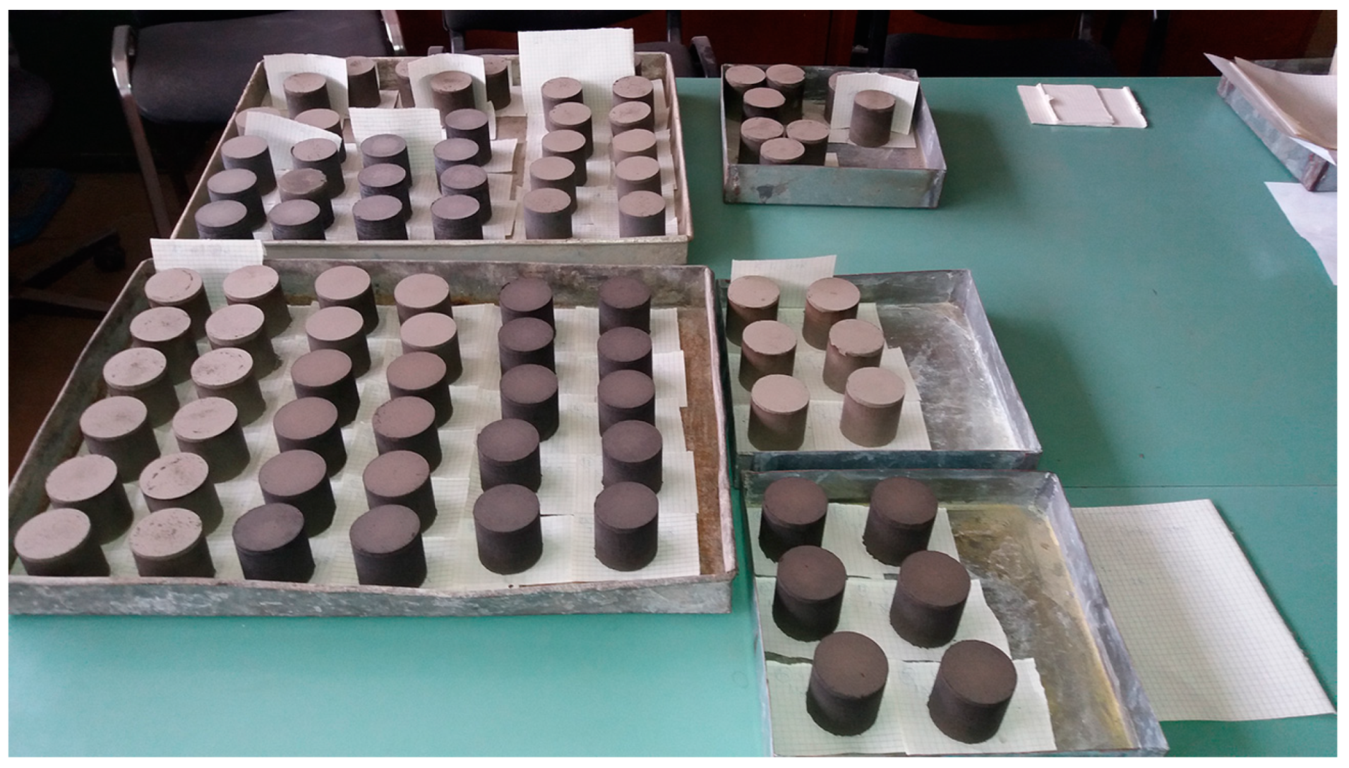
  • After 30 min of aging, the prepared mixture was poured into a steel mold (with dimensions of D × H = 50 × 81 mm) and subjected to a compacting force of 120 kN/m2 using a laboratory hydraulic press (manufactured by W. Feddeler, Essen, Germany).
  • Following extrusion from the mold, test specimens were measured, and their dimensions and weight were recorded. They were then appropriately labeled; subsequently, the test specimens were placed for aging under laboratory conditions, with ambient temperature maintained between 20 and 21 °C and relative humidity between 40 and 50%, while ensuring no exposure to direct sunlight.
  • The aging period was 1, 7, and 28 days, following which the test specimens were subjected to geo-mechanical tests. Prior to subsequent investigation, the test specimens were measured after aging, and their weight and dimensions were recorded.
  • The formed test specimens exhibited a cylindrical shape, with a diameter of 50 mm and a height of 51 ± 1 mm, as illustrated in Figure 1.

2.2.3. Preparation of New Mixture Samples for Wind Tunnel Testing

Based on the results obtained from the geo-mechanical tests, the most promising combinations of components were identified. Subsequently, mixtures embodying these combinations were prepared for the determination of dust emission rates in a laboratory wind tunnel. The preparation of mixtures followed steps 1–3. After a 30 min aging process, the mixture was evenly layered into metal trays, covered with lids, and compacted using a laboratory hydraulic press with a force of 120 kN/m2. The trays, measuring 250 × 500 × 20 mm (as depicted in Figure 2), were utilized. For each test conducted in the wind tunnel, a set of 6 trays, identical in size and content, was prepared.
The molds containing samples were positioned within a designated section of the wind tunnel, spanning a length of 1.5 m, as depicted in Figure 3. Concurrently, temperature and relative humidity measurements were conductwed within the same section using a thermo-hygrometer (Comet T3510, COMET SYSTEM, Vsetín, Czech Republic).

2.2.4. Measurement of Total Suspended Particles (TSPs)

For real-time measurements of the total suspended particles (TSPs) concentration (in mg/m3), a Micro Dust device (Casella Cel-712 PRO) (Casella, Bedford, UK) was employed, utilizing the light scattering method as its measuring principle. Prior to commencing measurements, zero and span values were calibrated. The measurement interval was set to 1 s, with an averaging period of 1 h. The device was positioned 130 cm downstream from the sample section’s airflow at a height of 25 cm.

2.2.5. Measurement of Concentration of PM10 Particles

The sampling of PM10 particles was conducted using a sequential sampler (Sven Leckel KAR8 + MVS6, Sven Leckel, Berlin, Germany), operating at a nominal flow rate of 2.3 m3/h. The measurement results are expressed in micrograms per cubic meter (μg/m3), where the air volume is specified at ambient conditions. The weight of the particles was determined by weighing the filter before and after sampling under strictly controlled conditions.
Clean quartz fiber filters (class T293; 47 mm) (Sartorius, Göttingen, Germany) were conditioned in the weighing room at a temperature (20 ± 1) °C and relative humidity 45%–50% before and after sampling for a period of 48 h. The filters were then weighed twice on the analytical scale (Sartorius CPA 225 D-0CE) (Sartorius, Göttingen, Germany) at an interval of 12 h, provided the difference in weight in successive filter weighing did not exceed 40 μg. The filters were then inserted into the sampling head seat, and sampling was carried out at a constant flow of 2.3 m3/h in a single hour. The sample filter was conditioned for a minimum of 48 h and then weighed on the analytical scale at 24 to 72 h intervals, provided the difference in filter weight did not to exceed 60 μg [26].

2.2.6. Calculating the Level of Suspended Particles Emission
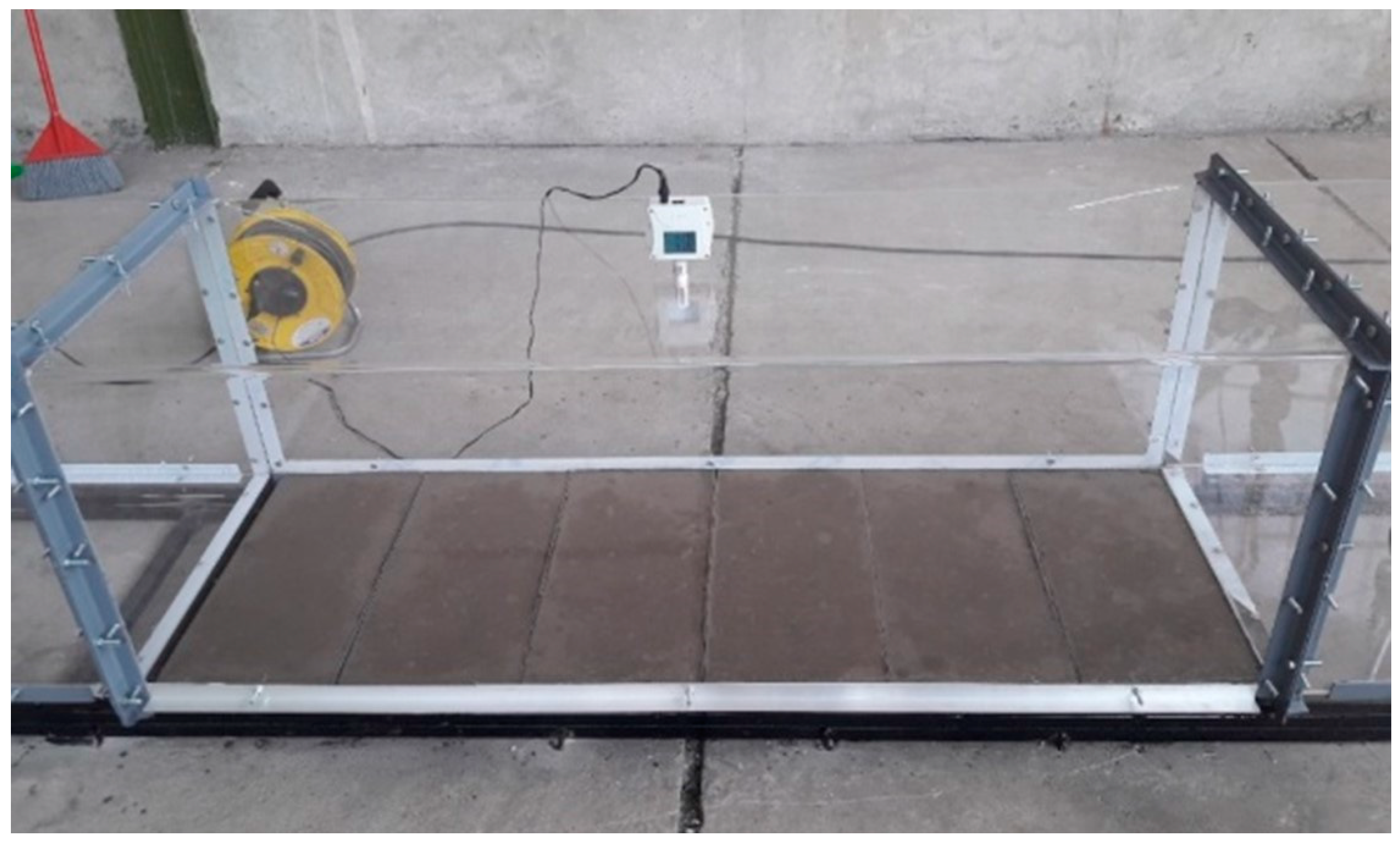
The PM10 emission level is determined based on the input (min) and the output ( m o u t ) mass flux through a certain volume (W × D × H). The emission source area (A) is determined as a product of length (L) and width (W), while H represents the height of the wind tunnel. The mass balance for the control volume gives the emission level (E).
E = 1 A ( m o u t m i n )
The mass flux can be determined based on the vertical particle concentration profile (C) and velocity (u) using the following formulas:
m o u t = 0 H C o u t u o u t V d z
m i n = 0 H C i n u i n V d z
which gives the following:
E = 1 L 0 H C o u t u o u t C i n u i n d z
If we assume that u o u t = u i n , where u o u t is the velocity of air exiting the control volume and u_in is the velocity of air entering the control volume, we can obtain the equation for the level of particle emission (E, µg/m2s) based on the test area (A) as follows:
E = C P M 10 × u × ( V · b A )
where b is the height at which measurement is conducted (0.17 m for PM10).

2.2.7. Wind Tunnel

The simulation of real conditions is achieved in a straight-line pressure wind tunnel, as depicted in Figure 4, which was designed and constructed by our team. The wind tunnel comprises the following components:
  • axial fan with frequency regulator;
  • section for air flow conditioning;
  • section for directing air flow;
  • section with samples;
  • section for measurement and sampling.
The tunnel length spans 5.5 m, with a cross-section area of 0.25 square meters. The length-to-height ratio, approximately 11, significantly surpasses the minimum threshold required for forming the boundary layer [27]. Velocity measurements were conducted using a DA4000 anemometer (Pacer Instruments by Miltronics Mfg., Inc, Keene, NH, USA) featuring a measuring range from 0.3 m/s to 35 m/s (±1% accuracy). Positioned along the central axis at a height of 0.25 m, the anemometer is situated 175 cm downstream from the airflow originating from the flow conditioner, as depicted in Figure 4.
Figure 4. Design of the wind tunnel (1—axial fan, 2—flow conditioning section, 3—flow straightening section, 4—wind velocity measurement, 5—sample tray section, 6—temperature and humidity measurement, 7—sampling/measurement section, 8—TSP measurement, 9—PM10 measurement).
Minerals 14 00809 g004
A grid measurement of flow velocity with the Pitot-Prandtl probe in three axes with five measuring points each (a total of fifteen points) was performed to determine the velocity profile in the cross-section of the tunnel [28].
The logarithmic wind profile has a solid theoretical background compared to the power law wind profile. The standard logarithmic wind profile, used to describe fluid flow over rough surfaces, requires the use of two unknown scaling parameters, the friction velocity, u * , and the aerodynamic roughness length, z 0 :
U z u * = 1 k l n z z 0 z 0
where U z is the wind velocity at height z above the surface, u * is the friction velocity, z 0 is the aerodynamic roughness length of the underlying surface, and k is the von Karman constant, usually assigned a value of approximately 0.4.
The friction velocity ( u * ) is a scaling velocity of the surface shear stress and is defined by the relationship which depends on the nature of the surface and mean velocity value:
u * = τ 0 ρ
where τ 0 is the wall shear stress and ρ is the air density.
The power law wind profile describes the mean profile by a simple power function of height as follows:
U z U r = z z r α
where U r is the known wind velocity at a reference height z r , and α is the power law exponent, which changes with terrain roughness [29,30].
These results demonstrate a correlation between the airflow velocity within the wind tunnel and the corresponding wind velocities at a reference height of 10 m. These data support the effectiveness of our wind tunnel in simulating real-world wind conditions.
The test design used in this study is common in both portable systems [31,32] and laboratory wind tunnels [33], though standards for step magnitude and duration are lacking. This design is efficient for testing numerous surfaces in the field.
Ten samples were prepared to investigate the effect of compression on the stabilization of the deposited mixture of ash and bottom ash. The composition of the tested samples is detailed in Table 2.

3. Results

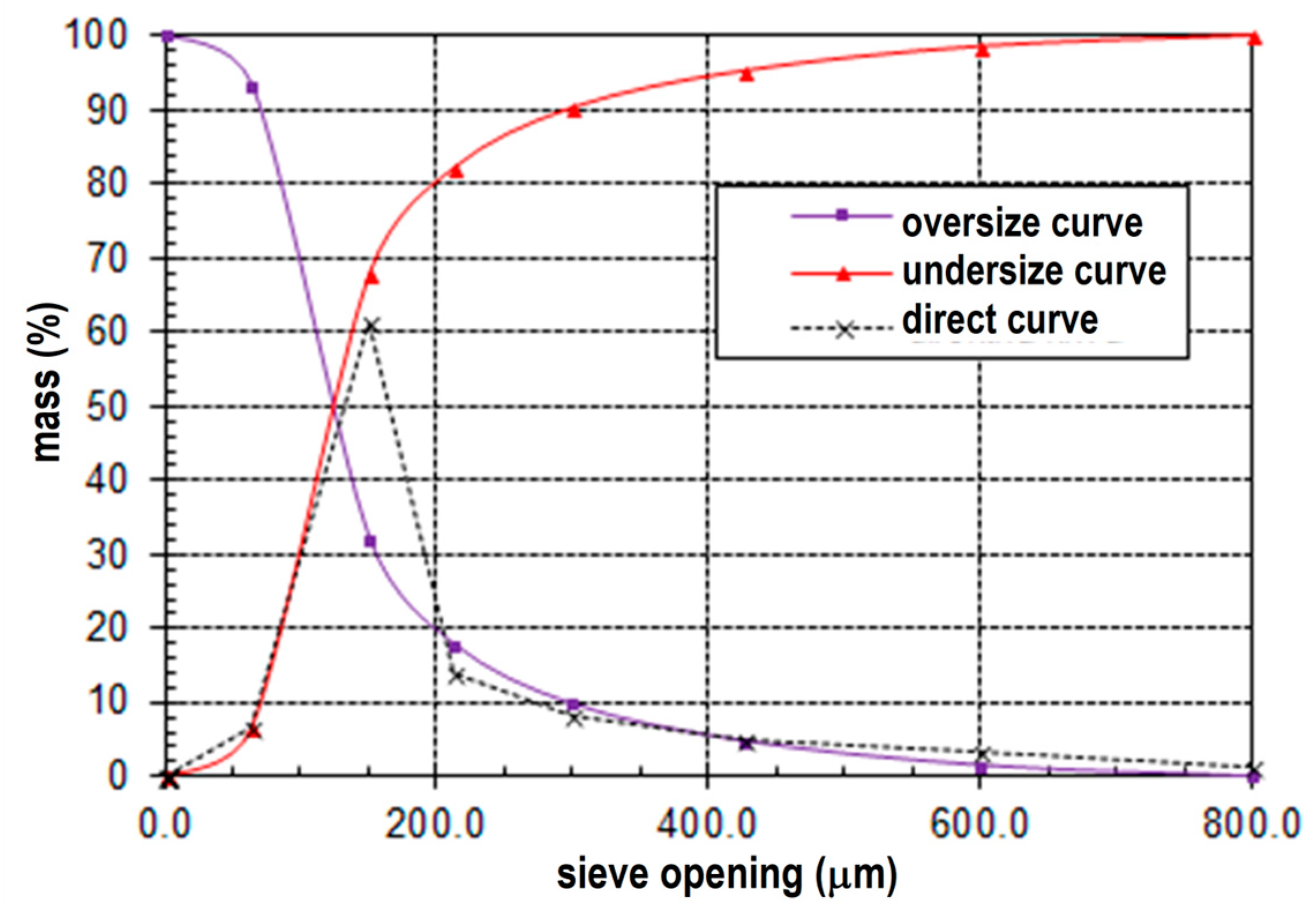
3.1. Particle Size Analysis

The particle size analysis of ash, bottom ash, and additives shows that fly ash predominantly comprises particles within the size class of 150 to 63 µm, commanding a notable share of 61.34%. This observation underscores the significance of this size range in defining the characteristics of fly ash.
Remarkably, hydrated lime (Ca(OH)₂) exhibits a marginally augmented prevalence of particles falling within the same size class, reaching a proportion of 80.50%. This modest increase in percentage underscores the similarity in particle size distributions between fly ash and hydrated lime, albeit with a slight variation in prevalence.
Of particular interest is the heightened occurrence of particles within the 150 to 63 µm size class in CaO, which is notably elevated at 93.16%. This pronounced predominance suggests a significant aggregation of particles within this size range, accentuating the distinctive particle size profile of CaO.
The particle size analyses of the investigated samples are meticulously delineated in Figure 5, Figure 6, Figure 7 and Figure 8.
Important data for defining certain technical and technological processes, specifically the mean particle diameter (d50) and upper size limit (d95), serve as key indicators for understanding particle size distribution and guiding process optimization efforts. These values can be obtained from Figure 5, Figure 6, Figure 7 and Figure 8. For the ash sample:
  • The mean particle diameter (d50) is determined to be 125 µm.
  • The upper size limit (d95) is observed to be 405 µm.
For hydrated lime:
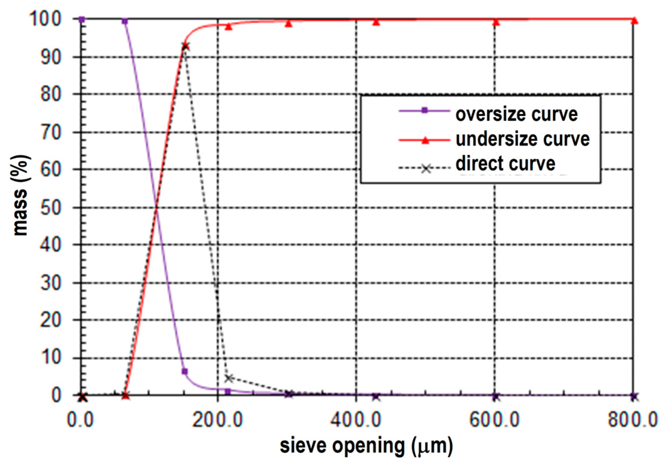
  • The mean particle diameter (d50) is measured to be 110 µm.
  • The upper size limit (d95) is determined to be 180 µm.
For quick lime:
  • The mean particle diameter (d50) is found to be 110 µm.
  • The upper size limit (d95) is identified as 160 µm.
For bottom ash:
  • The mean particle diameter (d50) is 700 µm.
  • The upper size limit (d95) is observed to be 3800 µm.

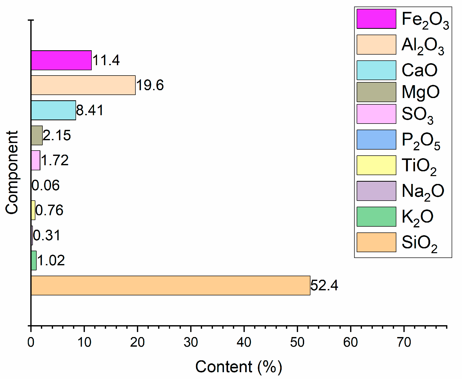
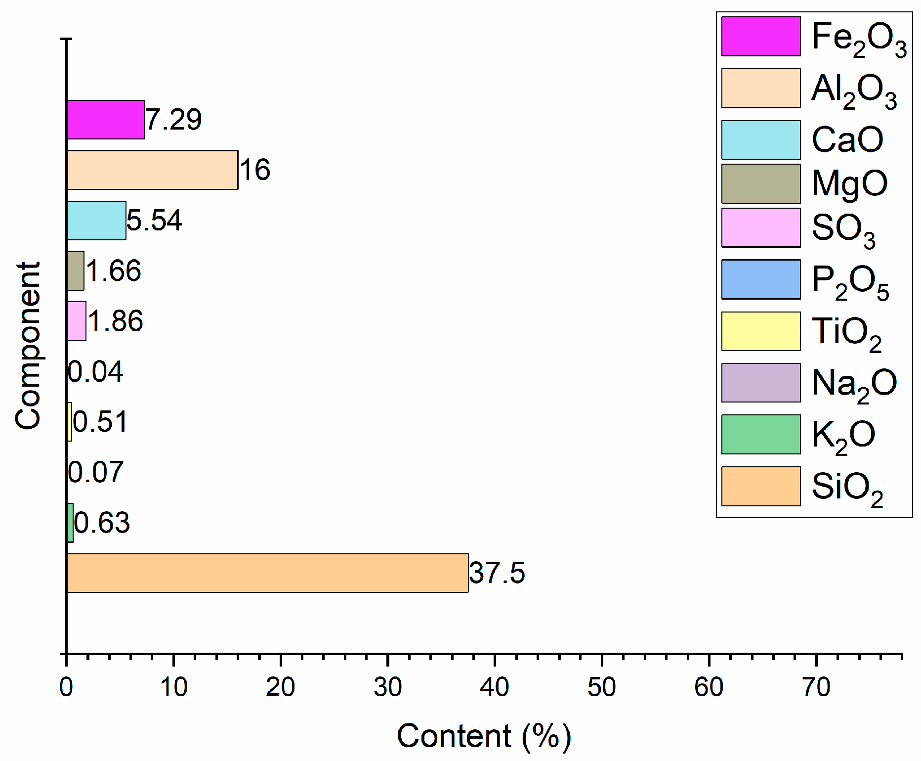
3.2. Results of Chemical Analysis

Based on the results obtained, the chemical composition of ash is depicted in Figure 9.
Based on the presented chemical composition, it is evident that the ash from TPP Kostolac B is classified as silicate ash, with SiO2 being the predominant component at 52.38%. These findings align with ASTM Standard C618 [34], indicating that the ash from TPP Kostolac B falls within the F ash class.
The combined percentage of SiO2, Al2O3, and Fe2O3 amounts to 83.34%, surpassing the requirement stipulated by the standard, which mandates it to be more than 70%. The SO3 content is measured at 1.72%, falling comfortably below the threshold set by the standard, which specifies it should be less than 5%. The loss of ignition is calculated to be 2.45%, well within the permissible limit outlined by the standard, which dictates it should be less than 6%.
Bottom ash is generally considered to be an inert material. Its lower chemical activity compared to ash is attributed to the larger size of bottom ash particles and the lower content of SiO2 and Al2O3, as confirmed by the diagram presented in Figure 10.
Based on the obtained results, it can be concluded that both additives, hydrated lime and quick lime, meet the quality standards outlined in the European standard EN 459-1 [35]. This standard specifies criteria regarding chemical composition, purity, reactivity, and other relevant parameters.
In the hydrated lime, the proportion of active Ca(OH)2 is 89.59%, with a total CaO content of 71.39%. The content of MgO is 1.66%, while the combined content of Fe2O3 and Al2O3 is 1.7%. In the quick lime, the proportion of active Ca(OH)2 is 91.41%, with a total CaO content of 93.1%. The content of MgO is 0.52%, and the combined content of Fe2O3 and Al2O3 is 1.2%.

3.3. Results of Bulk Density

The results of the bulk density test in the loose and compacted state (g/dm3) are presented in Table 3.
The density of the analyzed samples is presented in Table 4.
The bulk density of the compacted samples is depicted in Figure 11. The results indicate that, irrespective of the additive amount (1%, 2%, or 3%), the bulk density consistently decreases with aging time, stabilizing after 7 to 10 days. The accompanying diagram illustrates the average percentage weight loss of compacted test specimens relative to the aging time.
The highest weight loss occurs in test specimens composed of mixtures with bottom ash, followed by those without additives, while the test specimens with additives experience the least weight loss with aging.

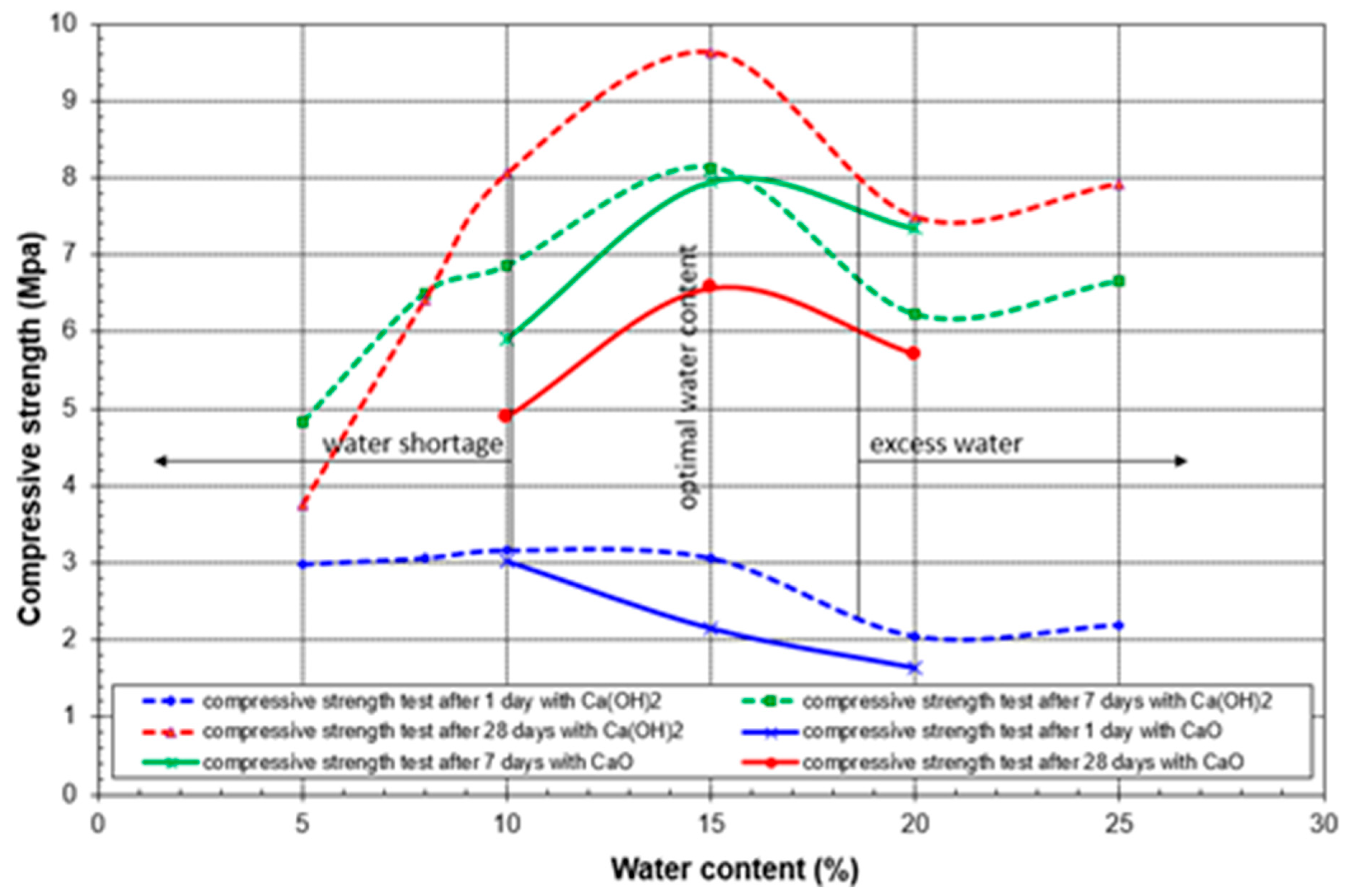
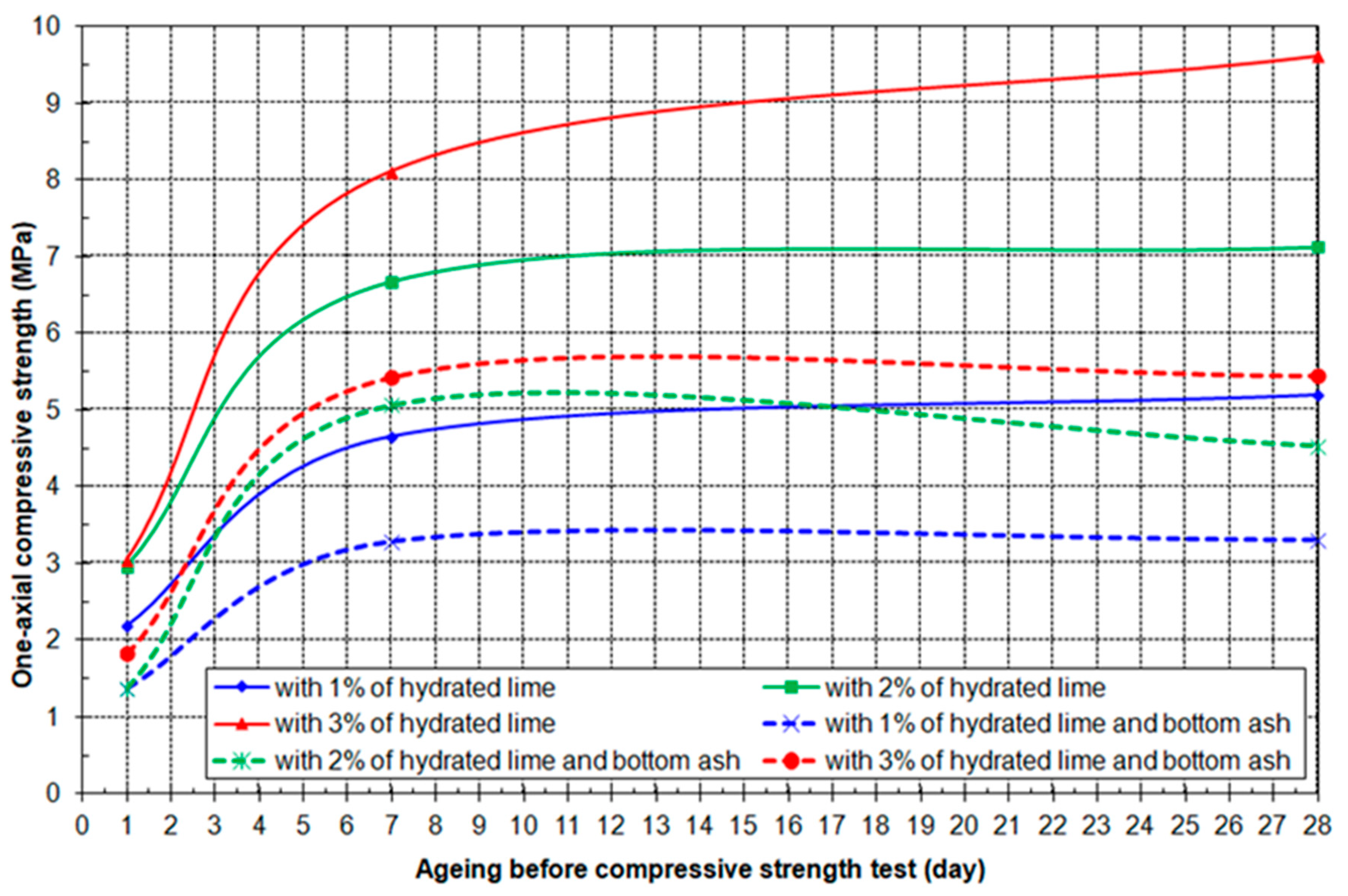
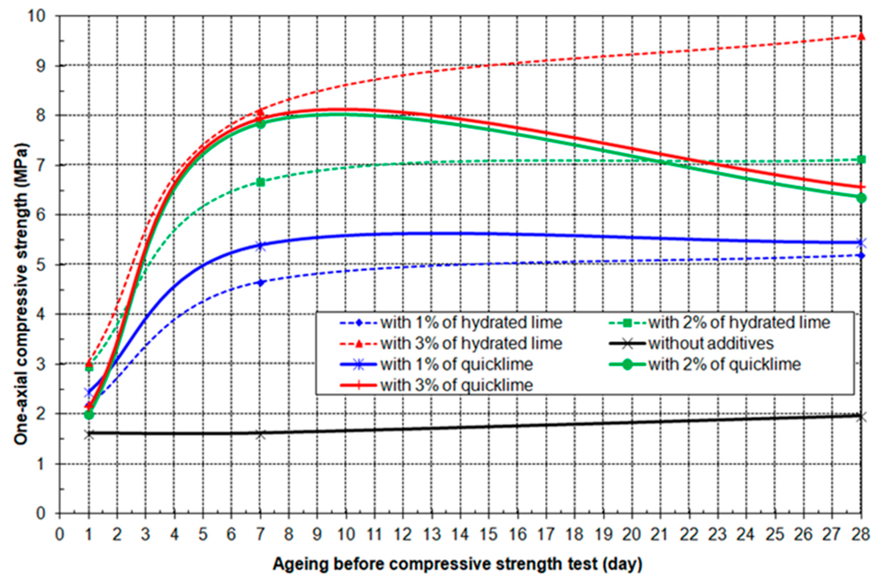
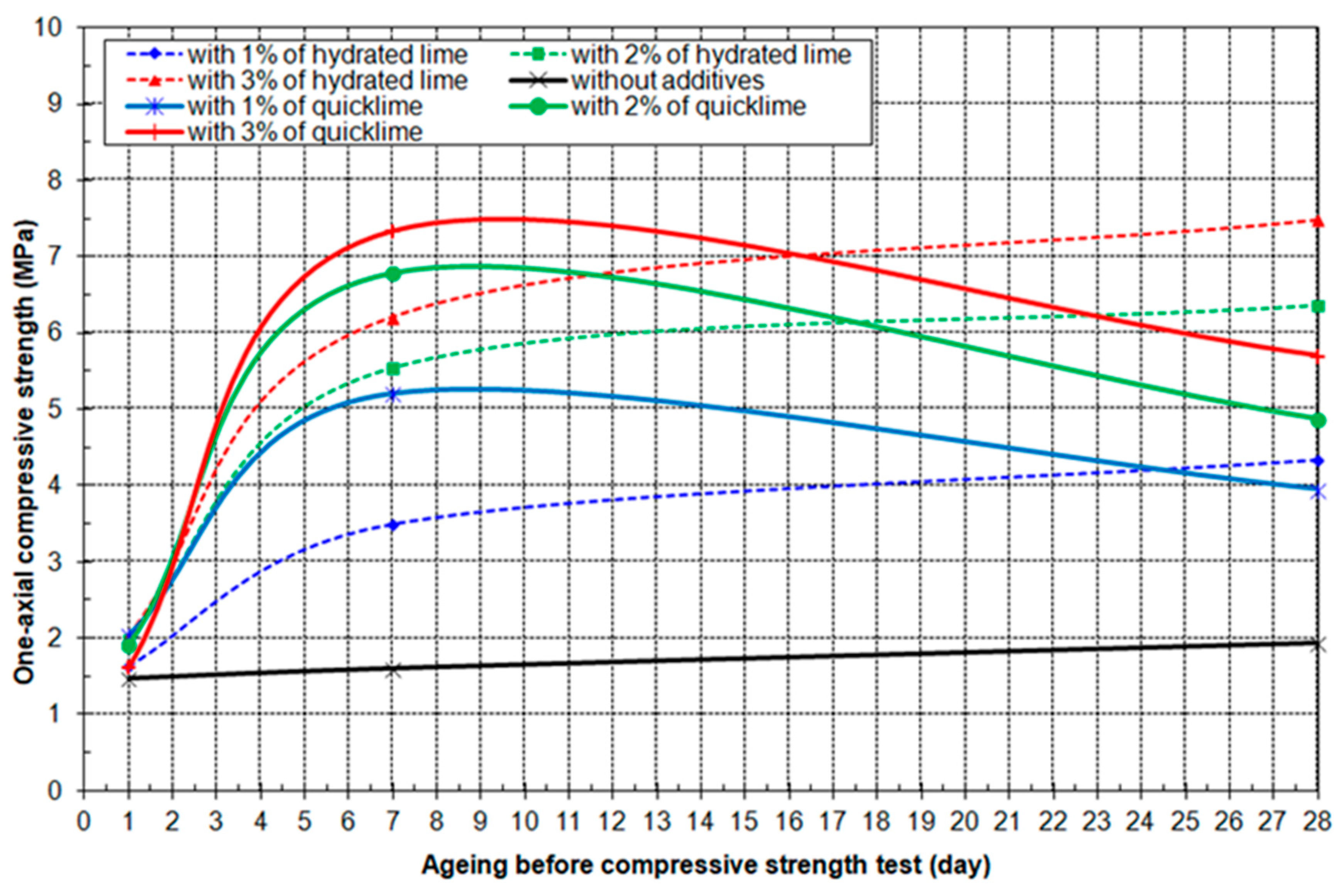
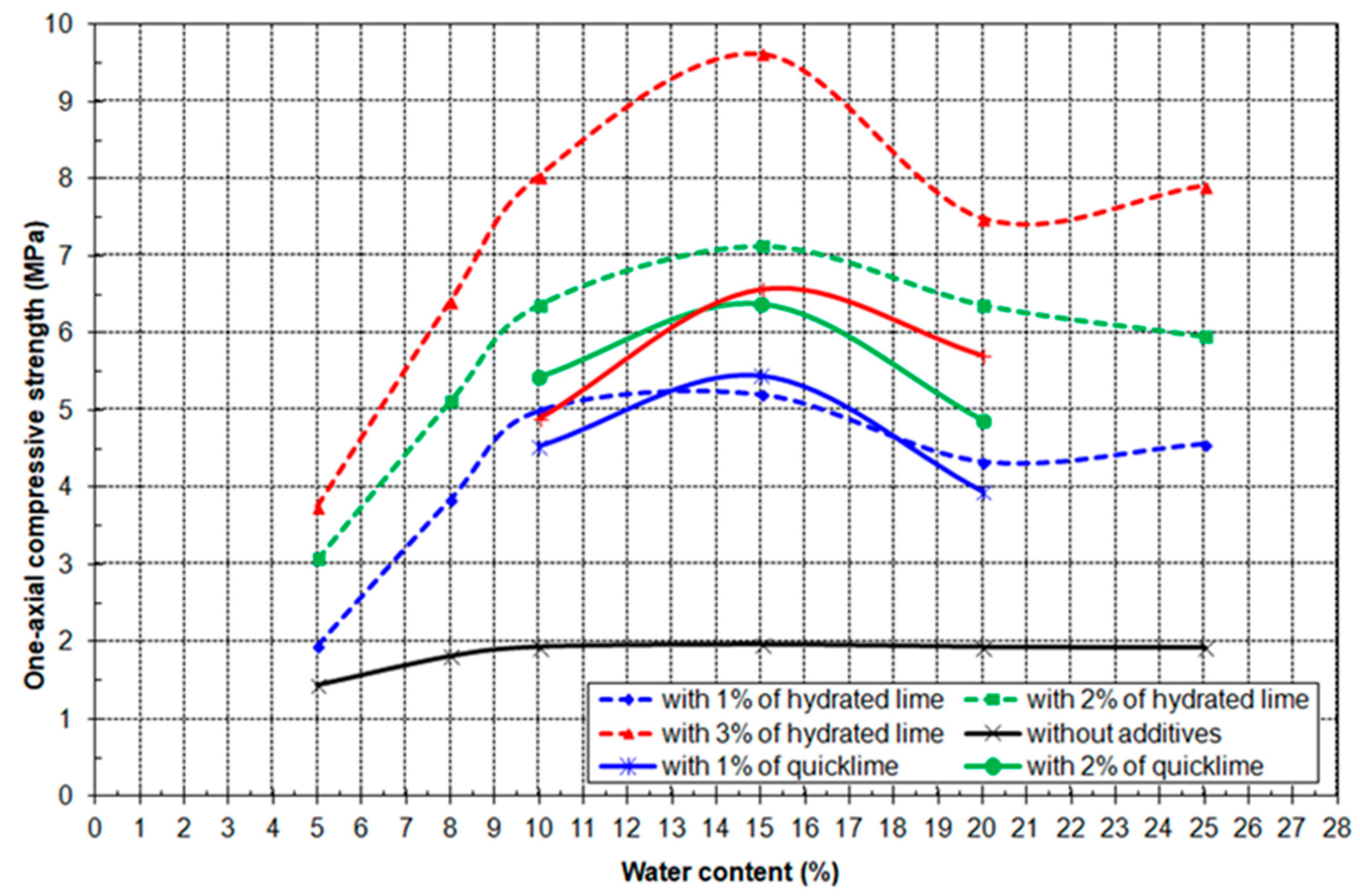
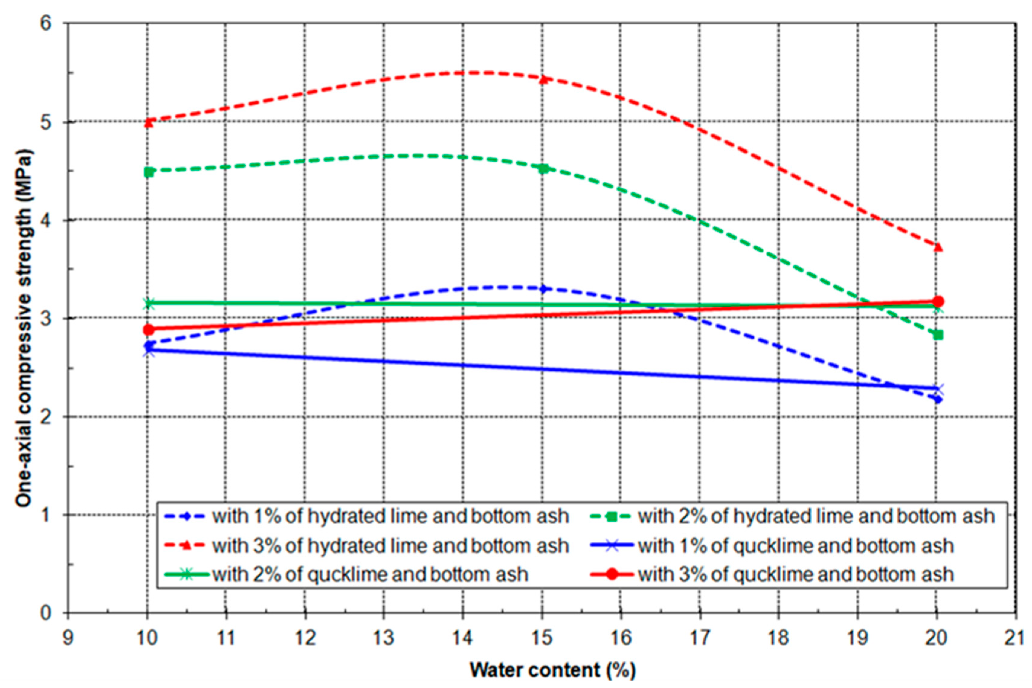
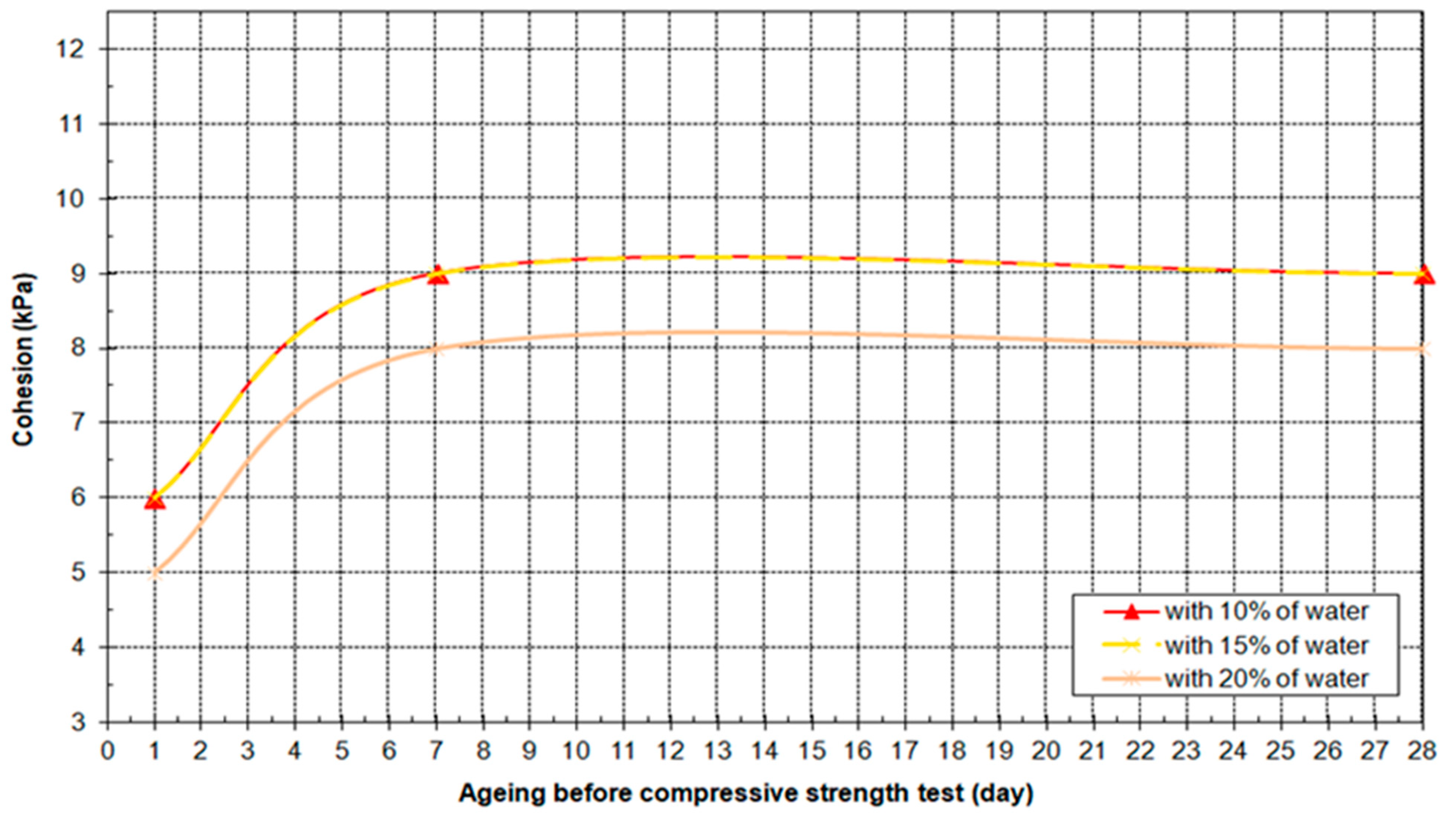
3.4. Results of Geo-Mechanical Testing

The following characteristic charts will demonstrate the dependence between the one-axial compressive strength and various factors such as water content, additive quantity, and aging time of the compacted mixture.
This chart (Figure 12) clearly indicates that, regardless of the aging time, the most optimal water content is 15%, coupled with 3% of Ca(OH)2 additive. The dependence between one-axial compressive strength after 28 days of aging and water content, as well as hydrated lime content for the ash mixture, is depicted in Figure 13.
With an optimal water content of 15%, the compressive strength increases with aging time. This diagram (Figure 14) clearly illustrates that the addition of bottom ash to the mixture significantly reduces the compressive strength.
The comparison of the previous two diagrams (Figure 15 and Figure 16) clearly shows that the compressive strength decreases with the addition of water beyond the optimal 15%.
The previous diagram (Figure 17) shows that the highest compressive strength after 28 days is achieved with 15% water and 3% Ca(OH)2. The dependence of the one-axial compressive strength of the ash and bottom ash mixture after 28 days of aging on the percentage of added water and hydrated/quick lime is illustrated in Figure 18.
The same principle applies when adding bottom ash to the mixture, albeit with a reduction in compressive strength compared to the ash mixture without bottom ash.
With 15% water and 3% Ca(OH)2, the cohesion is most favorable, as clearly visible in the illustrated diagram in Figure 19. However, with the addition of bottom ash, the cohesion decreases, as shown in Figure 20.

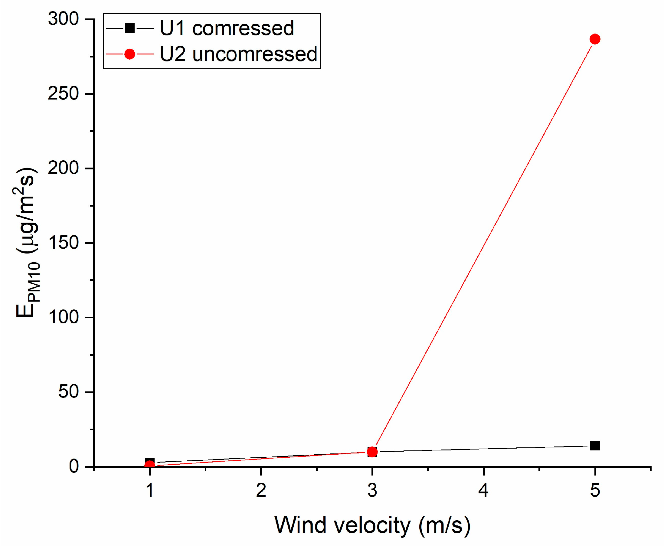
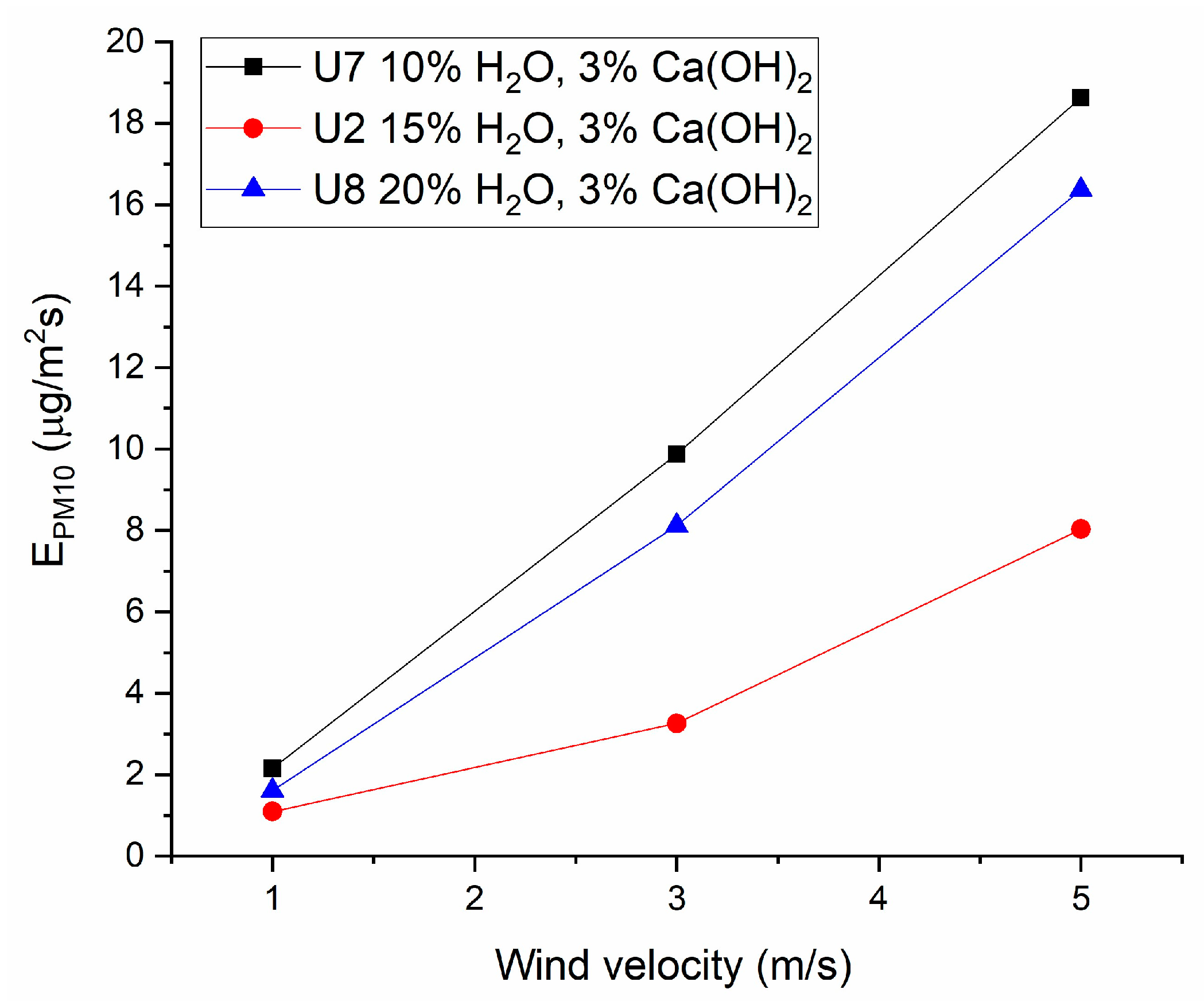
3.5. Results from Wind Tunnel Testing

According to the current domestic regulation [36], the daily mass concentration of PM10 suspended particles must not exceed the limit value of 50 µg/m3 more than 35 times in one calendar year. The limit value and the tolerance value for one calendar year are set at 40 µg/m3.
In the absence of an emission limit value, a useful indicator was to compare the obtained values with zero values of the concentration of PM10 particles (sample U0) that were measured in the wind tunnel without samples.
The level of emission of PM10 particles was calculated as the difference between PM10 measured concentrations and PM10 zero values. The maximum value of the EPM10/E0 ratio was used to estimate the size of the exceeded emission values. The results are shown in Table 5.
As observed from the results presented in Table 4, the PM10 emission values escalate with rising flow rates. The highest value of the EPM10/E0 ratio is recorded for the U4 sample (without additives and compression), while the lowest value is attributed to samples U2 and U3 (with 15% water and 3% additives Ca(OH)2 and CaO).
The impact of fly ash compression on PM10 emission is depicted in Figure 21.
It can be observed that fly ash compression exerts a notable impact on PM10 emissions, particularly noticeable at wind velocities exceeding 3 m/s.
The impact of additives on PM10 emission is illustrated in the following figure (Figure 22).
It is evident that incorporating additives into fly ash leads to a substantial reduction in PM10 emissions, and the level of PM10 emissions remains consistent when utilizing CaO as an additive compared to Ca(OH)2.
The impact of water content on PM10 emission is illustrated in the following figure.
From the results shown in Figure 23, it can be concluded that the lowest PM10 emissions were obtained with an additive content of 3%.
The impact of additives on PM10 emission is depicted in the following figure.
As illustrated in Figure 24, the minimum PM10 emission level is attained when employing the optimal combination of water content (15%) and additives (3%). Notably, the augmentation of additive content does not yield a discernible impact on PM10 emissions, particularly at wind velocities below 3 m/s.

4. Conclusions

The overarching aim of this investigation was to scrutinize the ramifications stemming from the potential dispersion of particles originating from deposited material, impacting both atmospheric and terrestrial environments. This endeavor involved the meticulous evaluation of particle emission levels across eight distinct samples, conducted under varying wind velocities, encompassing velocities of 1, 3, and 5 m per second. The findings suggest that the emission levels observed when incorporating CaO as an additive closely resemble those observed with Ca(OH)2. Moreover, the incremental increase in water content from 15% to 20% (with a 3% additive) does not exert a considerable influence on the PM10 emission levels. Furthermore, the augmentation of additive quantity, while maintaining a constant water content, reveals negligible impact on PM10 emissions, particularly at wind velocities below 3 m/s.
Drawing upon these findings, it can be deduced that the optimal additive content stands at 3%, while the optimal water content is determined to be 15%. Samples featuring this optimal composition of additives and water demonstrate PM10 emission levels that do not surpass zero values by more than 1.9 times. Such outcomes present a satisfactory outcome from an environmental protection standpoint.

Author Contributions

Conceptualization, J.N. and S.P.P.; methodology, J.N.; software, P.S.; validation, S.P. and A.M.; formal analysis, S.Ć.; investigation, S.Ć., J.N. and S.P.P.; resources, J.N.; data curation, S.P.; writing—original draft preparation, J.N. and S.P.P.; writing—review and editing, A.M., S.P., J.N. and S.P.P.; visualization, J.N.; supervision S.P.P.; project administration, S.P.P.; funding acquisition, P.S. All authors have read and agreed to the published version of the manuscript.

Funding

The authors express their gratitude for the support received from the innovation project of the Ministry of Education, Science, and Technological Development, under project number 391-00-16/2017-16/25, entitled: “Development of technologies for the joint disposal of ash, bottom ash, and gypsum from thermal power plants aimed at improving ecological and economic performances”.

Data Availability Statement

Data are contained within the article.

Conflicts of Interest

The authors declare no conflicts of interest.

References

  1. Chen, Y.; Xu, G.; Huang, J.; Eksteen, J.; Liu, X.; Zhao, Z. Characterization of coal particles wettability in surfactant solution by using four laboratory static tests. Colloids Surf. A Physicochem. Eng. Asp. 2019, 567, 304–312. [Google Scholar] [CrossRef]
  2. Wang, L.; Liu, Z.; Yang, H.; Li, H.; Yu, M.; He, T.; Luo, Z.; Liu, F. A novel biomass thermoresponsive konjac glucomannan composite gel developed to control the coal spontaneous combustion: Fire prevention and extinguishing properties. Fuel 2021, 306, 121757. [Google Scholar] [CrossRef]
  3. International Energy Agency. Global Coal Consumption Rises by 1.4% in 2023 to Record 8.5 Billion Metric Tons. 2024. Available online: https://www.iea.org/reports/coal-2023/executive-summary (accessed on 1 June 2024).
  4. Chen, J.; Cheng, S.; Song, M.; Wang, J. Interregional differences of coal carbon dioxide emissions in China. Energy Policy 2016, 96, 1–13. [Google Scholar] [CrossRef]
  5. International Energy Agency. Global Coal Demand Is Set to Return to Its All-Time High in 2022. 2022. Available online: https://www.iea.org/news/global-coal-demand-is-set-to-return-to-its-all-time-high-in-2022 (accessed on 30 May 2024).
  6. Han, W.; Zhou, G.; Wang, J.; Jiang, W.; Zhang, Q.; Kong, Y.; Miao, Y. Experimental investigation on combined modification for micro physicochemical characteristics of coal by compound reagents and liquid nitrogen freeze-thaw cycle. Fuel 2021, 292, 120287. [Google Scholar] [CrossRef]
  7. Wang, P.; Han, H.; Liu, R.; Gao, R.; Wu, G. Effect of outlet diameter on atomization characteristics and dust reduction performance of X-swirl pressure nozzle. Process Saf. Environ. Prot. 2020, 137, 340–351. [Google Scholar] [CrossRef]
  8. Hall, N.B.; Blackley, D.J.; Halldin, C.N.; Laney, A.S. Current review of pneumoconiosis among US coal miners. Curr. Environ. Health Rep. 2019, 6, 137–147. [Google Scholar] [CrossRef] [PubMed]
  9. Fidanchevski, E.; Angjusheva, B.; Jovanov, V.; Murtanovski, P.; Vladiceska, L.; Stamatovska Aluloska, N.; Krneta Nikolic, J.; Ipavec, A.; Šter, K.; Mrak, M.; et al. Technical and radiological characterisation of fly ash and bottom ash from thermal power plant. J. Radioanal. Nucl. Chem. 2021, 330, 685–694. [Google Scholar] [CrossRef]
  10. Singh, N.; Shehnazdeep, A.B. Reviewing the role of coal bottom ash as an alternative of cement. Constr. Build. Mater. 2020, 233, 117276. [Google Scholar] [CrossRef]
  11. Kim, K.H.; Kabir, E.; Kabir, S. A review on the human health impact of airborne particulate matter. Environ. Int. 2015, 74, 136–143. [Google Scholar] [CrossRef]
  12. Miao, L.; Wu, L.; Sun, X.; Li, X.; Zhang, J. Method for solidifying desert sands with enzyme-catalysed mineralization. Land Degrad. Dev. 2020, 31, 1317–1324. [Google Scholar] [CrossRef]
  13. Gadore, V.; Ahmaruzzaman, M. Tailored fly ash materials: A recent progress of their properties and applications for remediation of organic and inorganic contaminants from water. J. Water Process Eng. 2021, 41, 101910. [Google Scholar] [CrossRef]
  14. Oberdörster, G.; Sharp, Z.; Atudorei, V.; Elder, A.; Gelein, R.; Lunts, A.; Kreyling, W.; Cox, C. Extrapulmonary translocation of ultrafine carbon particles following whole-body inhalation exposure of rats. J. Toxicol. Environ. Health 2002, 65, 1531–1543. [Google Scholar] [CrossRef] [PubMed]
  15. Mahamaya, M.; Das, S.K.; Reddy, K.R.; Jain, S. Interaction of biopolymer with dispersive geomaterial and its characterization: An eco-friendly approach for erosion control. J. Clean. Prod. 2021, 312, 127778. [Google Scholar] [CrossRef]
  16. Malviya, R.; Chaudhary, R. Factors affecting hazardous waste solidification/stabilization: A review. J. Hazard. Mater. 2006, 137, 267–276. [Google Scholar] [CrossRef] [PubMed]
  17. Li, X.D.; Poon, C.S.; Sun, H.; Lo, I.M.C.; Kirk, D.W. Heavy Metal Specifications and Leaching Behaviors in Cement Based Solidified/Stabilized Waste Materials. J. Hazard. Mater. 2001, 82, 215–230. [Google Scholar] [CrossRef] [PubMed]
  18. Georgescu, M.; Andronescu, C.; Zahanagiu, A. Immobilization of harmful substances in binder matrices. Part I. Immobilization capacity. Influence on binding properties. Rev. Rom. Mater. 2006, 3, 189–197. [Google Scholar]
  19. Vijan, A.C.; Badanoiu, A.; Voicu, G.; Nicoara, A.I. Phosphate cements based on calcined dolomite: Influence of calcination temperature and silica addition. Materials 2021, 14, 3838. [Google Scholar] [CrossRef] [PubMed]
  20. Nešković, J.; Stjepanović, P.; Milojković, N.; Lazić, D.; Konc Janković, K. Solidification/stabilization technology of by products (ash) from power plants. In Proceedings of the 8th Balkan Mining Congress, Belgrade, Serbia, 28–30 September 2022; pp. 345–354, ISBN 978-86-82673-21-7. [Google Scholar] [CrossRef]
  21. Xie, S.; Zhang, X.; Pang, Y. Wind Dynamic Characteristics and Wind Tunnel Simulation of Subgrade Sand Hazard in the Shannan Wide Valley of the Sichuan–Tibet Railway. Int. J. Environ. Res. Public Health 2022, 19, 8341. [Google Scholar] [CrossRef] [PubMed]
  22. Demarco, G.; Martins, L.G.N.; Bodmann, B.E.J.; Puhales, F.S.; Acevedo, O.C.; Wittwer, A.R.; Costa, F.D.; Roberti, D.R.; Loredo-Souza, A.M.; Degrazia, F.C.; et al. Analysis of thermal and roughness effects on the turbulent characteristics of experimentally simulated boundary layers in a wind tunnel. Int. J. Environ. Res. Public Health 2022, 19, 5134. [Google Scholar] [CrossRef]
  23. Zhao, Z.; Chang, P.; Ghosh, A.; Xu, G.; Liu, Y.; Morla, R. The influence of surfactants’ ionicity on the performance of coal dust suppression. Adv. Powder Technol. 2024, 35, 104295. [Google Scholar] [CrossRef]
  24. EN 1097-3:1999; Tests for Mechanical and Physical Properties of Aggregates. Determination of Loose Bulk Density And Voids. iTeh, Inc.: Newark, DE, USA, 1998.
  25. Vujić, S.; Radosavljević, M.; Makar, N.; Marijanac, S.; Nešković, J.; Gigov, M.; Žarković, M.; Hafner Ljubenović, T.; Belić, D.; Bužalo, A. Fifty-five years of the Mining Institute. Bull. Mines 2015, CXII, 1–27. [Google Scholar]
  26. BS EN 12341:2023; Ambient Air. Standard Gravimetric Measurement Method for the Determination of the PM10 or PM2.5 Mass Concentration of Suspended Particulate Matter. European Standards: Plzen, Czech Republic, 2023.
  27. Scott Van Pelt, R.; Zobeck, M.T. Chapter 3, Portable Wind Tunnels for Field Testing of Soils and Natural Surfaces, Wind Tunnel Designs and Their Diverse Engineering Applications; IntechOpen: London, UK, 2013; Volume 17. [Google Scholar]
  28. ISO 16911-1:2013; Stationary Source Emissions Manual and Automatic Determination of Velocity and Volume Flow Rate in Ducts Part 1: Manual Reference Method. International Standards: Geneva, Switzerland, 2013.
  29. Tennekes, H. The logarithmic wind profile. J. Atmos. Sci. 1973, 30, 234–238. [Google Scholar] [CrossRef]
  30. White, B.R. Laboratory simulation of aeolian sand transport and physical modeling of flow around dunes. Ann. Arid Zone 1996, 35, 187–213. [Google Scholar]
  31. Etyemezian, V.; Gillies, J.A.; Mastin, L.G.; Crawford, A.; Hasson, R.; Van Eaton, A.R.; Nikolich, G. Laboratory experiments of volcanic ash resuspension by wind. J. Geophys. Res. Atmos. 2019, 124, 9534–9560. [Google Scholar] [CrossRef]
  32. Goossens, D.; Buck, B. Dust dynamics in off-road vehicle trails: Measurements on 16 arid soil types, Nevada, USA. J. Environ. Manag. 2009, 90, 3458–3469. [Google Scholar] [CrossRef]
  33. Macpherson, T.; Nickling, W.G.; Gillies, J.A.; Etyemezian, V. Dust emissions from undisturbed and disturbed supply-limited desert surfaces. J. Geophys. Res. Earth Surf. 2008, 113, F02S04. [Google Scholar] [CrossRef]
  34. ASTM Standard C618-22; Standard Specification for Coal Fly Ash and Raw or Calcined Natural Pozzolan for Use in Concrete. ASTM International: West Conshohocken, PA, USA, 2023.
  35. European Standard EN 459-1; Building Lime Definitions, Specifications and Conformity Criteria. iTeh, Inc.: Newark, DE, USA, 2015.
  36. Regulation on Conditions for Monitoring and Air Quality Requirements; no. 11/10, 75/10 and 63/13; Official Gazette of the Republic of Serbia: Belgrade, Serbia, 2013.
Figure 1. Geo-mechanical test specimens.
Minerals 14 00809 g001
Figure 2. Test specimens for wind tunnel testing.
Minerals 14 00809 g002
Figure 3. Sample tray section within the wind tunnel.
Minerals 14 00809 g003
Figure 5. Particle size analysis of ash.
Minerals 14 00809 g005
Figure 6. Particle size analysis of hydrated lime.
Minerals 14 00809 g006
Figure 7. Particle size analysis of quick lime.
Minerals 14 00809 g007
Figure 8. Particle size analysis of bottom ash.
Minerals 14 00809 g008
Figure 9. Chemical composition analysis of ash.
Minerals 14 00809 g009
Figure 10. Chemical composition analysis of bottom ash.
Minerals 14 00809 g010
Figure 11. Correlation between bulk density and aging time.
Minerals 14 00809 g011
Figure 12. Dependence between one-axial compressive strength and water content.
Minerals 14 00809 g012
Figure 13. Dependence of one-axial compressive strength after 28 days of aging on water and hydrated lime content for the ash mixture.
Minerals 14 00809 g013
Figure 14. Dependence of one-axial compressive strength during aging of ash and bottom ash mixture with 15% water content on hydrated lime content.
Minerals 14 00809 g014
Figure 15. Dependence of one-axial compressive strength during aging of ash mixture with 15% of water on percentage of added hydrated/quick lime.
Minerals 14 00809 g015
Figure 16. Dependence of one-axial compressive strength during aging of ash mixture with 20% of water on percentage of added hydrated/quick lime.
Minerals 14 00809 g016
Figure 17. Dependence of one-axial compressive strength during aging of ash mixture on the percentage of added water and hydrated/quick lime.
Minerals 14 00809 g017
Figure 18. Dependence of one-axial compressive strength of ash and bottom ash mixture after 28 days of aging on the percentage of added water and hydrated/quick lime.
Minerals 14 00809 g018
Figure 19. The dependence of cohesion of the ash mixture with 3% hydrated lime on the percentage of added water.
Minerals 14 00809 g019
Figure 20. Dependence of cohesion of ash and bottom ash mixture with 3% of hydrated lime on aging and percentage of added water.
Minerals 14 00809 g020
Figure 21. PM10 emission rate vs. wind velocity for compressed and uncompressed samples.
Minerals 14 00809 g021
Figure 22. PM10 emission rate vs. wind velocity for different types of binder.
Minerals 14 00809 g022
Figure 23. PM10 emission rate vs. wind velocity for different water contents.
Minerals 14 00809 g023
Figure 24. PM10 emission rate vs. wind velocity for different binder contents.
Minerals 14 00809 g024
Table 1. Comparison of wind velocities in wind tunnel and at 10 m height.
Velocity in Wind Tunnel, m/sWind Velocity at 10 m, m/s
12.82
38.45
where:
z 10 m
z 0 0.0003 m—according to the European Wind Atlas for sand surfaces (smooth)
z r 0.05 m—the height in the wind tunnel at which the velocity is measured
α α = 1 l n ( z r z 0 ) = 0.17
Table 2. The composition of the tested samples.
Sample No.Fly Ash Content %Water Content %CaO %Ca(OH)2 %Bottom Ash Content %
U17915--6
U27615-36
U376153-6
U47415-56
U58410--6
U68210-26
U78110-36
U87120-36
Table 3. Bulk density in loose and compacted state.
Bulk DensityLoose StateCompacted State
Sample(g/dm3)(g/dm3)
Ash812.531032.63
Bottom ash467.70533.47
Ca(OH)2497.80671.30
CaO642.70849.60
Table 4. Density of analyzed samples.
SampleAshBottom AshCa(OH)2CaO
Density (g/cm3)2.12.12.43.6
Table 5. The values of the PM10 emission rates and maximum values of the EPM10/E0 ratio.
Sample No.Wind Velocity (m/s)EPM1 (µg/m2s)EPM10/E0 (max)
U010.6-
33.3
513.8
U112.74.8
39.9
513.9
U211.11.9
33.3
58.0
U311.11.9
33.3
58.4
U410.620.8
39.9
5286.6
U513.45.9
313.2
529.9
U612.74.8
310.1
522.0
U712.13.8
39.9
518.6
U811.62.8
38.1
516.4
Disclaimer/Publisher’s Note: The statements, opinions and data contained in all publications are solely those of the individual author(s) and contributor(s) and not of MDPI and/or the editor(s). MDPI and/or the editor(s) disclaim responsibility for any injury to people or property resulting from any ideas, methods, instructions or products referred to in the content.

