Abstract
Time-optimal trajectory planning is one of the most important ways to improve work efficiency and reduce cost and plays an important role in practical application scenarios of robots. Therefore, it is necessary to optimize the running time of the trajectory. In this paper, a robot time-optimal trajectory planning method based on quintic polynomial interpolation and an improved Harris hawks algorithm is proposed. Interpolation with a quintic polynomial has a smooth angular velocity and no acceleration jumps. It has widespread application in the realm of robot trajectory planning. However, the interpolation time is usually obtained by testing experience, and there is no unified criterion to determine it, so it is difficult to obtain the optimal trajectory running time. Because the Harris hawks algorithm adopts a multi-population search strategy, compared with other swarm intelligent optimization algorithms such as the particle swarm optimization algorithm and the fruit fly optimization algorithm, it can avoid problems such as single population diversity, low mutation probability, and easily falling into the local optimum. Therefore, the Harris hawks algorithm is introduced to overcome this problem. However, because some key parameters in HHO are simply set to constant or linear attenuation, efficient optimization cannot be achieved. Therefore, the nonlinear energy decrement strategy is introduced in the basic Harris hawks algorithm to improve the convergence speed and accuracy. The results show that the optimal time of the proposed algorithm is reduced by 1.1062 s, 0.5705 s, and 0.3133 s, respectively, and improved by 33.39%, 19.66%, and 12.24% compared with those based on particle swarm optimization, fruit fly algorithm, and Harris hawks algorithms, respectively. In multiple groups of repeated experiments, compared with particle swarm optimization, the fruit fly algorithm, and the Harris hawks algorithm, the computational efficiency was reduced by 4.7019 s, 1.2016 s, and 0.2875 s, respectively, and increased by 52.40%, 21.96%, and 6.30%. Under the optimal time, the maximum angular displacement, angular velocity, and angular acceleration of each joint trajectory meet the constraint conditions, and their average values are only 75.51%, 38.41%, and 28.73% of the maximum constraint. Finally, the robot end-effector trajectory passes through the pose points steadily and continuously under the cartesian space optimal time.
Keywords:
time-optimal trajectory planning; quintic polynomial interpolation; Harris hawks algorithm; nonlinear energy decrement strategy MSC:
49J30; 49L20
1. Introduction
In recent years, robots have been utilized extensively in welding, spraying, handling, palletizing, and other forms of automated production [1]. Trajectory planning is the foundation of motion control for robots. It generates the time series of the robot’s position, velocity, and acceleration at each point along the smooth path, based on the required performance index [2]. The performance, motion stability, and energy consumption of industrial robots are strongly influenced by the quality of their planning. Therefore, trajectory planning has long been a topic of interest among experts at home and abroad [3]. The planning of robot trajectories can be separated into cartesian space planning and joint space planning. Planning trajectories in cartesian space require a continuous correlation between the path of the end-effector and the path in joint space. Its inverse solution requires a great deal of calculation, and the process of solving [4] involves singular-value problems. However, the inverse solution of joint space trajectory planning takes less computing, allowing the singular-value problem to be avoided during the solution process. Moreover, it can modify the time variation of the position, angular velocity, and angular acceleration of the robot joints in real time in accordance with the design specifications [5]. Therefore, the joint space trajectory planning method is utilized in this paper.
Time-optimal trajectory planning aims to minimize the robot’s running time. Depending on the motion law, a time-optimal trajectory is planned based on the specified constraints. Industrial robots must increase job efficiency and economic benefits [6]. In actual production, however, the central issue is ensuring that the robot end-effector completes the task smoothly and stably and reaches the specified position in the shortest time possible [7]. The robot trajectory generation method includes the case where interpolation is required and the case where interpolation is not required [8,9]. The polynomial interpolation function makes it easy to determine the boundary state of a robot trajectory due to its simple and fast calculation and is frequently used for robot trajectory planning [10]. Therefore, this paper primarily studies the time-optimal trajectory planning problem in the case of the polynomial interpolation function. Quintic polynomial interpolation not only solves the problems of cubic polynomial interpolation’s non-smooth angular velocity and jump acceleration but also avoids the problems of cubic polynomial interpolation’s complex calculation methods and many constraints [11]. Therefore, it has apparent advantages.
The literature [12] proposed a robot trajectory planning method based on piecewise continuous functions. This technique enhanced the velocity of quintic polynomial interpolation by combining the properties of the trapezoidal function and the trigonometric function. Finally, an experimental platform consisting of a 4-DOF manipulator was used to verify the trajectory. The results indicated that this strategy effectively reduces execution time. Analooee A. et al. [13] proposed a novel trajectory planning method based on explicit quintic polynomial curves. The boundary curvature constraint conditions were constructed using the rotation coordinate reference for the border condition and standardized programming. It was demonstrated that the proposed method could create optimal trajectory running time compared to previous methods. In the literature [14], the ideal robot time trajectory was determined by adding restrictions for torque and acceleration and using the convex optimization approach.
Although the methods mentioned above have yielded some results, it is difficult to determine the optimal time trajectory due to the limitations of polynomial interpolation trajectory planning [15], such as its high order, lack of convex hull property, and a large number of setting parameters. The emergence of intelligent optimization algorithms has made time-optimal trajectory planning with intelligent algorithms a worthy objective. Li Y et al. [16] proposed the improved cuckoo search technique to optimize polynomial interpolation time. A trajectory simulation was performed in a shared space using the UR robot as the research object. The suggested technique delivers a better time-optimal trajectory under velocity limitations than the traditional cuckoo search algorithm, particle swarm optimization algorithm, and genetic algorithm. The literature [17] proposed the highly smoothing time-optimal trajectory approach of a manipulator based on the adaptive elite genetic algorithm. This strategy was combined with quintic polynomials. Experimental results demonstrated that the proposed method was more effective than the original genetic algorithm, ensuring the robot’s smooth and efficient operation. The literature [18] indicated that variable weight particle swarm optimization was employed to optimize the robot’s running time. To ensure the accurate and secure operation of fracture reduction and orthopedic robots, it is possible to avoid the issue of unequal soft and hard traction rates.
Heidari et al. developed the Harris Hawks Optimization (HHO) algorithm in 2019 as a novel swarm intelligence optimization algorithm [19]. Similar to other swarm intelligent optimization algorithms such as particle swarm optimization (PSO) and fruit fly optimization algorithms (FOA), it has the advantages of good applicability, robustness, and easy implementation [20]. It is widely used in the fields of time series prediction, neural network parameter optimization, task cooperative planning, and other fields [21]. The difference is that HHO adopts a multi-population search strategy. It can avoid problems such as single population diversity, low mutation probability, limited search space, and local extreme values of PSO and FOA. However, because some key parameters in HHO are simply set to constant or linear attenuation, efficient optimization cannot be achieved [22]. Improved local and global optimization values were suggested as a means of enhancing the performance of basic HHO. The literature [23] proposed the chaotic Harris hawks optimization. Utilizing chaos mapping and a simulated annealing approach, the existing optimal solution was optimized, and the HHO optimization accuracy was enhanced. Fan Q et al. coupled the HHO method and a quasi-reflection-based learning mechanism and evaluated it on 23 distinct benchmark function types and dimensions [24]. The results indicated that it significantly enhanced the convergence rate and solving precision of basic HHO. In addition, hawks optimization was incorporated into HHO to improve the accuracy with which reliability problems might be solved [25]. Many improvements focusing on HHO were elaborated in the past few years, but few researchers could balance both global and local extremes.
This paper proposes a robot time-optimal trajectory-planning approach based on quintic polynomial interpolation and the improved Harris hawks algorithm (IHHO). The starting point, two intermediate points, and the terminating point of the robot end-effector are provided. Inverse kinematics was used to determine the angular positions of each joint when the end-effector passed through the set path point. Each joint’s adjacent angular positions are related by quintic polynomials. The angular velocity curve and the angular acceleration curve can be derived from the diagonal position curve in the first and second orders. HHO was utilized to optimize the running time within the limitations of the maximum angular displacement, angular velocity, and angular acceleration of each joint to overcome the challenge of calculating the best running time of polynomial interpolation trajectory planning. Meanwhile, a nonlinear energy attenuation technique is presented to improve the energy attenuation factor E1 to adapt and transition global search and local mining and enhance convergence accuracy and speed. Finally, taking total running time synchronization as the criterion, the maximum time of each joint in the same stage was obtained. Each joint’s kinematic constraints can be satisfied, and the optimal-time trajectory can be planned.
The rest of the paper is organized as follows: The robot kinematics model, quintic polynomial interpolation algorithm, and objective function for trajectory optimization are introduced in Section 2. Section 3 introduces the fundamental principle of HHO, its improvement, and the planning procedure. In Section 4, the strategies for time-optimal trajectory planning based on several biological algorithms are compared. Under optimal time, the trajectory of each joint and end-effector is analyzed. The superiority and efficacy of the proposed procedures are verified. Under optimal time, the trajectory of each joint and end-effector is analyzed. Section 5 summarizes some conclusions and prospects.
2. Description of the Problem
2.1. Kinematic Model of Robot
The 6-DOF rotary joint robot is utilized extensively in polishing, spraying, and other applications. Currently, it is the most prevalent robot structure [26]. Therefore, this paper takes the PUMA560 6-DOF robot as the research object, and all joints are revolute joints. Its physical model and D-H coordinate system are shown in Figure 1 [27]. In Figure 1, X, Y, and Z axes are determined by the right-hand rule. The base coordinate system is , and the coordinate system of connecting rod is . The parameters of each connecting rod are defined as follows [28]:
- (1)
- is the distance from to along the axis.
- (2)
- is the angle of rotation from to around the axis.
- (3)
- is the distance from to along the axis.
- (4)
- is the angle of rotation from to around the axis.
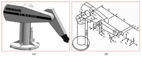
Figure 1.
(a) Physical model; (b) D-H coordinate system.
The D-H method is used for modeling, then the homogeneous transformation matrix of the coordinate system relative to the coordinate system is:
where is the joint angle, is the length of the connecting rod, is the angle of the connecting rod, and is the offset distance of the connecting rod. Then the forward kinematics of the robot can be solved as follows:
where is the position and posture matrix of the robot terminal relative to the base coordinate system.
The inverse kinematics solution describes the mapping relationship between the terminal cartesian space and the joint space of the robot. The inverse kinematic of each joint variable is solved as follows [29]:
2.2. Quintic Polynomial Interpolation
Cartesian space node positions of robot end-effectors are known. Cartesian space is converted into joint space by the inverse kinematics equation of the robot, and the path node angle position of each joint in joint space is solved. The time corresponding to each node angle position is , where is the number of nodes in the planned trajectory. Interpolation using quintic polynomials is widely employed in the field of robot trajectory planning [30]. The angle values of 0 rad at 0 s, 25 rad at 3 s, 75 rad at 6 s, 50 rad at 12 s, and 0 rad at 14 s were fitted and connected by quintic polynomial interpolation. The angular velocity curve and angular acceleration curve were obtained by calculating the first and second derivatives of the angular curve, respectively. Figure 2 showed the trajectory planning results of the quintic polynomial interpolation. The results indicate that there are no apparent abrupt changes in the position, velocity, or acceleration curves. The absence of mechanical vibration and increased friction is beneficial to the robot. Therefore, this paper employs quintic polynomial interpolation for trajectory planning.
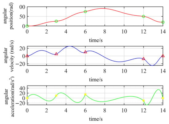
Figure 2.
Quintic polynomial interpolation trajectory planning result.
The starting point, intermediate point, and endpoint are fitted by quintic polynomial interpolation. The relation between fitting time and angular position is:
where is the angular position of the i-th path node of the j-th joint, are the coefficients of the equation corresponding to the angle position of the i-th path node of the j-th joint, and is the time corresponding to the angle position of the i-th path node of the j-th joint.
Thus, the angular velocity is:
Then, the angular acceleration is:
where satisfies:
According to the above formula, the corresponding quintic polynomial coefficient matrix can be solved when the joint angular position, angular velocity, and even angular acceleration are determined, and the time is given. In this paper, the joint angular position and the starting and ending angular velocity are known and is obtained by the IHHO. Thus, can be solved.
2.3. Trajectory Optimization Objective Function
The objective of quintic polynomial interpolation is to solve the unknown coefficients of polynomials under the condition that the interpolation time of each segment is known, hence determining the beginning and end trajectory of each joint. It is difficult to produce a time-optimal trajectory [31] because there is no consistent criterion for determining the interpolation time of each segment during trajectory design, and the interpolation time is typically determined by human experience. The primary objective of this paper is to use the IHHO to determine the robot’s shortest movement time under kinematic constraints. The objective function is as follows:
The constraint conditions of angular position, angular velocity, and angular acceleration are as follows:
where is the joint number of the robot, is the number of path points, and is their maximum value. In this paper, the trajectory is optimally analyzed for = 4, = 6, and . Low values of correspond to a better fitness value.
3. Time-Optimal Trajectory Optimization Method of Robot
3.1. Harris Hawks Optimization Algorithm
HHO is a new algorithm for population evolution proposed by Heidari et al. in 2019 [19]. The steps of the HHO process are as follows [32]:
- (1)
- First, the population position is initialized, and the target matrix is set up to store the fitness values of Harris hawks in each iteration. The initial position matrix is:where represents the value of the j-th dimension of the i-th Harris hawk, is the total number of Harris hawks, and represents the dimension of the question. The target matrix is:where is the fitness function.
- (2)
- All individual position dimensions generated during each iteration are examined. The population position is updated, according to (12).where is the position of the i-th updated Harris hawk, X(i,:) is the position of the i-th Harris hawk, is the matrix composed of a dimension of the i-th Harris hawk position greater than the upper limit of the search space, and is the matrix composed of a dimension of the i-th Harris hawk position smaller than the lower limit of the search space.
- (3)
- The value of the prey’s escape energy determines the different behavior of Harris hawks. Formula is:where x is the number of current iterations, is the random number between (−1,1), is the maximum number of iterations, and represents the nonlinear energy attenuation factor.
- (4)
- When , the algorithm enters the stage of global search. Depending on whether q is greater than 0.5, it is divided into two predation strategies. The formula for the global search stage is as follows:where represents the position of the next generation of Harris hawks. is the position of prey. represents the current average position of the Harris hawk group, referring to (15). represents the position of random individuals in the Harris hawk group. is the current position of the Harris hawks. is the random number between (0, 1).where represents the position of each Harris hawk in iteration x.
- (5)
- When , the Harris hawk group enters the local search phase and has four round-up methods, given below.
Soft besiege: When and , the mathematical model at this stage is:
where is the random jump intensity of the prey, and is the random number in the interval Hard besiege: When and , the model at this stage is:
Soft besiege with progressive rapid dives: When and , the model at this stage is:
where represents the fitness value of the minimization problem and and are:
where represents the random vector with size , denotes the dimension of the problem, and is as follows:
where and are random numbers on (0,1), and is set to 1.5.
Hard besiege with progressive rapid dives: When and , the mathematical model of this stage is:
where and are, respectively:
- (6)
- Determine whether the current iteration times x reaches the maximum iteration times or the required precision. If so, output the current optimal solution; otherwise, continue searching. The hunting behavior of Harris hawks is shown in Figure 3 [33].
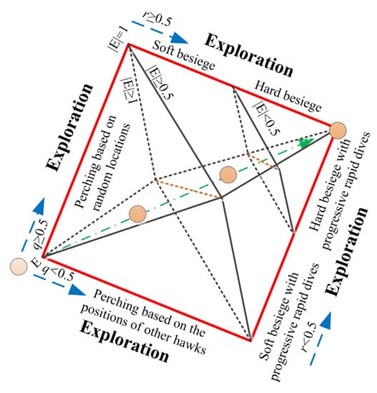 Figure 3. Process of the hunting behavior of the Harris hawks.
3.2. Improvement of HHO
From the basic HHO, it can be seen that the size of plays an important role in adjusting and transitioning global search and local mining. The smaller is, the more inclined HHO is to perform local mining, and the larger is, the more inclined HHO is to explore globally [34]. In addition, the prey energy decay factor determines the overall trend of escape energy [35]. However, in the traditional HHO, updates mode decreases linearly from 2 to 0, which does not accurately describe the real process of energy consumption of Harris eagles in nature when they hunt prey [34]. In other words, the energy consumption of the prey during the initial days of the Harris hawks colony when it was spotted and pursued varied greatly. As the prey eventually entered the ring of encirclement, the Harris hawks group did nothing except circle around, and as the prey regained some resting energy and its consumption slowed. In later periods, Harris Hawks hunted prey, and the prey’s energy requirements were altered dramatically once more. Alternatively, in the process of improvement, it is necessary not only to ensure the global search capability in the early stage and the transition from global search to local search in the middle stage but also to ensure the local development capability in the late stage and accelerate the local search. Therefore, the nonlinear energy decline strategy is proposed to improve , which is expressed as follows:
Then, the improved is expressed as:
where represents the number of iterations, is the maximum number of iterations, and denotes a random number of .
Figure 4 shows the variation trend of the prey energy attenuation factor in the interval (0,2) before and after improvement when the number of iterations T = 600. Compared with the original , the improved decreases rapidly in the early stage from 0 to 200 generations, which controls the global search ability of the algorithm. The middle stage of 200 to 400 generations changes slowly, balancing global and local search capabilities. The later stages of 400 to 600 generations were rapidly reduced to speed up the local search while ensuring strong local development capabilities. The updated pattern also matches the actual energy expenditure of hunted prey. As shown in Figure 5, the overall change trend of is the same as that of . Processes and pseudocodes of IHHO are shown in Figure 6 and Algorithm 1.
| Algorithm 1. Pseudocode of IHHO. |
| Inputs: N and T |
| Outputs: Xrabbit |
| Initialize Xi (i = 1, 2, …, N) |
| While (Termination has not happened) do |
| Calculate the fitness values |
| Set Xrabbit as the best solution |
| for (each solution (Xi)) do |
| Update E0 and jump strength J E0 = 2 rand ()−1, J = 2(1-rand ()) |
| Update E refer to (26). |
| If (|E| ≥ 1) then Exploration phase (global search) |
| Updating process performs referring to (14). |
| If (|E| < 1) then Exploitation phase (local search) |
| If (r ≥ 0.5 and |E| ≥ 0.5) then |
| Updating process performs referring to (16). |
| else if (r ≥ 0.5 and |E| < 0.5) then |
| Updating process performs referring to (17). |
| else if (r < 0.5 and |E| ≥0.5) then |
| Updating process performs referring to (18). |
| else if (r < 0.5 and |E| < 0.5) then |
| Updating process performs referring to (22). |
| Return Xrabbit |
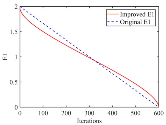
Figure 4.
Curves of improved E1 and original E1.
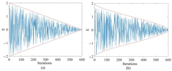
Figure 5.
(a) The original E. (b) The improved E.
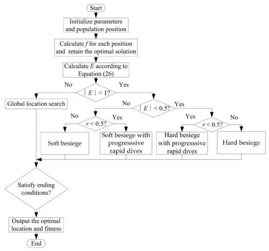
Figure 6.
Flowchart of IHHO.
3.3. Planning Process
IHHO is used to optimize the time of the joint within the constraints of the maximum angular position, angular velocity, and angular acceleration of each joint to produce the optimal running time of the robot trajectory. A robot time-optimal trajectory planning method is proposed based on quintic polynomial interpolation and the improved Harris hawks algorithm. The algorithm’s main flow is as follows:
Step 1. The parameters such as population size , maximum Iteration times , optimization dimension , the upper limit of search space , the lower limit of search space , and the initial fitness value are initialized. The population location is also initialized. In the optimal trajectory planning method based on quintic polynomial interpolation and IHHO, , , and are the parameters to be optimized and generated by IHHO.
Step 2. Check that all dimensions of the generated group of times fall within the specified range and adjust them for updates. Equation (8) is used to calculate the fitness value of the updated groups of time successively.
Step 3. The N sets of fitness values are compared with the initial fitness value . The in N sets of fitness values that is less than initial fitness value is retained. The corresponding time group is also preserved. Then the corresponding quintic polynomial coefficient matrix of is solved. Among them, the restrictions for solving are the angular position and the starting and ending angular velocity of the optimized joint. In the search dimension space of , and , the angular position , angular velocity , and angular acceleration equations in , and periods are established by . Then equations satisfying the constraints of maximum angular position , angular velocity , and angular acceleration are sought. The time group corresponding to the equations satisfying the constraints are preserved. The fitness values of the time group are traversed and compared in turn. The best time group and the best fitness value are retained. The best fitness value is assigned to .
Step 4. According to the escape energy of the prey, groups time of the next generation is generated, and steps 2 and 3 are repeated. The fitness value is less than and the corresponding time group is obtained. The time group corresponding to the equations satisfying the constraints is found. The optimal time group and the optimal fitness value of this generation are obtained by comparing the fitness of . The is assigned to , and the position of the population is updated.
Step 5. Determine whether the maximum number of iterations is reached or whether the error meets the preset accuracy. If so, the iteration will be terminated, and the optimal time group and the optimal fitness value of the optimized joint will be output. The flowchart of the process can be seen in Figure 7.
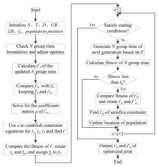
Figure 7.
Robot time-optimal trajectory planning process.
4. Simulation
4.1. Comparative Analysis of Time Optimization
The connecting rod parameters of PUMA560 robot are shown in Table 1. In order to determine the angular position of each joint by solving inverse kinematics, a joint space–time trajectory optimization study was performed. It is important to identify the path points of the robot end-effector in the cartesian coordinate system as well as the constraints of angular location, angular velocity, and angular acceleration of each joint. Table 2 displays the path points of the end-effector in the cartesian coordinate system for the denim-polishing process. As indicated in Table 3, the angular position of each joint corresponding to the path points in cartesian coordinate systems was calculated using inverse kinematics. Table 4 shows the maximum constraint values for the angular position, angular velocity, and angular acceleration for each robot joint.

Table 1.
Connecting rod parameter of PUMA560 robot.

Table 2.
Robot cartesian space path points.

Table 3.
Angular position of robot joint space (rad).

Table 4.
Maximum constraints of joint angular position, angular velocity, and angular acceleration.
The performance of the proposed method was validated by simulating and comparing the time-optimal trajectory planning based on PSO, FOA, HHO, and the algorithm proposed in this paper. The following parameters were set for time-optimal trajectory planning based on PSO: Set population size = 30, self-learning factor = 1.4, group learning factor = 1.4, inertia weight = 0.8, maximum Iteration times = 600, dimension of optimization problem = 3, the upper limit of search space = 4, lower limit of search space = 0, initial fitness value = 10, and initial speed and end speed are both 0 [36]. The parameters of the time-optimal trajectory planning based on FOA are set as follows: Set population size = 30, maximum Iteration times = 600, optimization dimension = 3, the upper limit of search space = 4, the lower limit of search space = 0, and initial fitness value = 10. The search range = 10 and the flight distance = 1. The parameters of the time-optimal trajectory planning based on HHO and IHHO are set as follows: Set population size = 30, maximum Iteration times = 600, optimization dimension = 3, the upper limit of search space = 4, and the lower limit of search space = 0. The initial fitness value = 10 and in IHHO is updated according to (26). In accordance with the time-optimal trajectory planning procedure, the time-optimal solution for each joint under the motion constraint was subsequently determined. Table 5 exhibits the optimal time for each robot segment based on PSO, FOA, HHO, and IHHO. The configuration of the workstation utilized for all calculations in this section is detailed in Table 6.

Table 5.
The optimal interpolation time of each segment of each joint (s).

Table 6.
Configuration of the workstation.
Due to the varying constraints of various joints, the time required for each joint to reach its destination varies. In practice, however, the end-effector accurately traverses the path point in the task space, and the rotation time of each joint is identical when reaching the target point. In order to satisfy the motion constraints of each joint, the maximum time of each segment is selected from all joints. Thus, the results of time-optimal trajectory planning based on PSO are = 1.9439 s, = 1.4205 s, and = 1.4064 s; then, the optimal time is 4.7708 s. The results of time-optimal trajectory planning based on FOA are = 1.6946 s, = 1.2318 s, and = 1.3293 s; then, the optimal time is 4.2557 s. The results of time-optimal trajectory planning based on HHO are = 1.3145 s, = 0.9903 s, and = 1.1142 s; then, the optimal time is 3.6210 s. The results of time-optimal trajectory planning based on IHHO are = 1.2808 s, = 0.8906 s, and = 1.0064 s; then, the optimal time is 3.1778 s. Compared with the optimal trajectory planning based on PSO, FOA, and HHO, the optimal trajectory planning based on IHHO decreased by 1.1062 s, 0.5705 s, and 0.3133 s, respectively, and improved by 33.39%, 19.66%, and 12.24%. The effectiveness of the proposed algorithm in robot trajectory time optimization was proven.
4.2. Comparative Analysis of Convergence of Algorithm
Due to the limited length of the article, joint 1, one of the first three joints that control the robot’s position, was used as an example to demonstrate that the proposed algorithm provided superior convergence speed and precision. The objective function and constraint conditions for optimization remained unchanged. In 50 groups of repeated experiments, the four algorithms discussed in this paper were utilized. The computational efficiency of the four algorithms is displayed in Table 7. Figure 8 depicts the iterative process of time optimization for joint 1 by four optimization algorithms. Other joint algorithms yielded similar optimization outcomes to joint 1.

Table 7.
Computational efficiency results of four optimization algorithms.
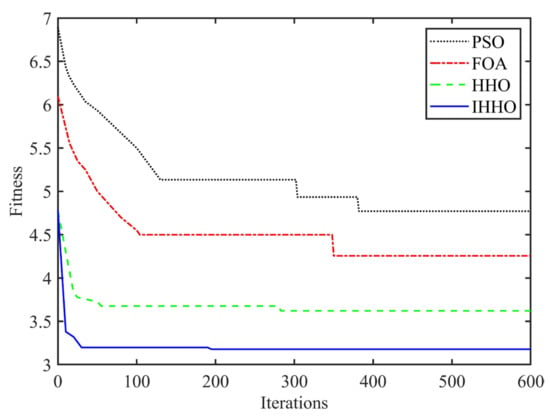
Figure 8.
Iterative process of four optimization algorithms.
Table 7 and Table 8 reveal that the average calculation time for the IHHO algorithm was 4.2697 s. Compared to PSO, FOA, and HHO, the average calculation time was reduced by 4.7019 s, 1.2016 s, and 0.2875 s or by 52.40%, 21.96%, and 6.30%, respectively. As shown in Figure 8, the time optimization based on the IHHO algorithm has a low fitness in the 30th generation, and the best fitness is close to 3.1778 s in the 190th generation. In contrast, the fitness of the time optimization based on PSO, FOA, and HHO decreased significantly after the 30th generation. The optimal time for each algorithm appeared in 4.7708 s of the 380th generation, 4.2557 s of the 350th generation, and 3.6210 s of the 283rd generation, in that order. They are all larger than 3.1778 s based on IHHO’s 190th generation. This demonstrated the proposed algorithm’s superior convergence speed and precision.

Table 8.
IHHO compared with the other three algorithms’ computational efficiency increase percentage.
4.3. Joint and End-Effector Trajectory Analysis
After determining the optimal running time of the robot using IHHO, MATLAB was used to program it to achieve the optimal trajectory for each joint. Figure 9 depicts the time-dependent angular position, angular velocity, and angular acceleration curves for each of the six joints. The maximum angular displacement, angular velocity, and angular acceleration of each joint trajectory at the optimal time are shown in Table 9.
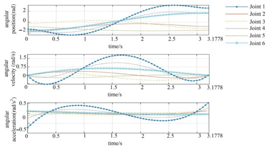
Figure 9.
Angular position, angular velocity, and angular acceleration curves of each joint.

Table 9.
Maximum angular position, angular velocity, and angular acceleration of each joint under optimal time (rad).
As depicted in Figure 9, the angular motion trajectory of each joint was smooth, and the states of the beginning, end, and middle points are all in accordance with the parameter settings. During the motion, the angular position, angular velocity, and angular acceleration had no mutation. Additionally, each joint’s position change was relatively smooth, which aided in reducing the running time. The speed of the second segment of the first joint was close to the maximum permitted speed, which was conducive to efficiency improvement. The maximum constraint percentage of the angular position, angular velocity, and angular acceleration of each joint is shown in Table 10. The maximum angular positions of the joints are,, in percentage terms, 99.60%, 37.03%, 94.16%, 98.51%, 83.21%, and 40.59%, respectively, of the maximum constraint angular positions. The maximum angular speeds are 98.22%, 22.62%, 25.81%, 42.98%, 8.26%, and 32.57%, respectively, of the maximum constrained angular speeds. The maximum angular accelerations were 95.71%, 22.53%, 12.77%, 20.99%, 9.48%, and 11.22% of the maximum constrained angular accelerations, respectively. At the angular position level, the average value was only 75.51% of the maximum constraint, 38.41% of the maximum constraint at the angular velocity level, and 28.73% of the maximum constraint at the angular acceleration level. Each robot joint’s angular position curve, angular velocity curve, and angular acceleration value can satisfy the constraint conditions. Within the constraints, the optimal trajectory time obtained by the algorithm ensured smooth, stable, and continuous angular displacement, velocity, and acceleration curves for each joint.

Table 10.
Angular position, angular velocity, and angular acceleration of each joint accounted for the maximum constraint percentage.
As depicted in Figure 10, the SerialLink, Fkine, and Transl functions of the Robotics Toolbox in MATLAB were used to perform robot simulation modeling, forward kinematics calculation, and draw the end-effector trajectory under the optimal time in cartesian space. The black dot represents the path point, and it can be seen that the trajectory of the robot end-effector passed through the path point stably without interruption. The last waypoint is reunited with the end-effector. It demonstrated that the proposed algorithm yielded the optimal trajectory time in joint space and also ensured the accurate and stable continuation of the robot end-effector trajectory in cartesian space. It was demonstrated that the proposed algorithm is feasible.
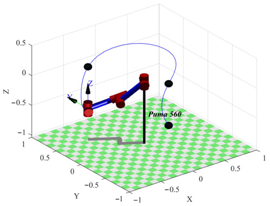
Figure 10.
The end-effector trajectory under the optimal time in Cartesian space.
5. Conclusions and Future Work
This paper proposes a time-optimal trajectory planning method for robots based on quintic polynomial interpolation and an improved Harris hawks algorithm. The nonlinear energy reduction strategy is introduced in the basic HHO to improve the convergence speed and precision. The PUMA560 robot serves as the platform for experimental verification. Using quintic polynomial trajectory interpolation, the starting point, intermediate point, and endpoint of each joint are fitted in the joint space. Under the constraints of angular displacement, angular velocity, and angular acceleration, the IHHO was utilized to optimize the trajectory time of each joint, with the target being the sum of each running time. Total running time synchronization was used to determine the optimal running time of the robot. The experimental results demonstrated that the proposed algorithm decreases the maximum time by 1.1062 s, 0.5705 s, and 0.3133 s, respectively, and improves by 33.39%, 19.66%, and 12.24% when compared to algorithms based on PSO, FOA, and HHO, respectively. In multiple groups of repeated experiments, the computational efficiency was reduced by 4.7019 s, 1.2016 s, and 0.2875 s relative to PSO, FOA, and HHO and increased by 52.40%, 21.96%, and 6.30%, respectively. It demonstrated that the proposed algorithm converges more quickly and precisely. The maximum angular position, angular velocity, and angular acceleration of each joint trajectory satisfy the constraint conditions under the optimal time. Their average values fell short of the maximum limit by 75.51%, 38.41%, and 28.73%, respectively. Under optimal time in cartesian space, the trajectory of the robot’s end-effector passed through the pose point continuously and continuously. Verification of the feasibility of the proposed algorithm.
However, this method also has some drawbacks, most notably the following: The proposed method only optimizes the robot’s running time for a single objective, but optimizing the robot for multiple objectives is a study-worthy problem. On the other hand, parameters in the optimization process are determined based on previous research and a large number of simulation experiments rather than a strict mathematical derivation. Several refinements and additional investigations of the proposed method are scheduled for the future. These include the determination of appropriate optimization parameters, multi-objective robot optimization, and physical robot testing.
Author Contributions
Methodology, J.X. and C.R.; software, X.C.; formal analysis, X.C.; writing—original draft, C.R.; writing—review and editing, J.X.; funding acquisition, J.X. All authors have read and agreed to the published version of the manuscript.
Funding
The support of the National Natural Science Foundation of China (No. 51905229), Natural Science Foundation of Jiangsu Province (No. BK20190968), China Postdoctoral Science Foundation (No. 2019M661975), and Marine Equipment and Technology Institute of Jiangsu University of Science and Technology (No. HZ20220009) in carrying out this research are gratefully acknowledged.
Data Availability Statement
The data that support the findings of this study are available from the corresponding author upon reasonable request.
Conflicts of Interest
The authors declare no conflict of interest.
Nomenclature
| Acronym and Variable | Definition |
| HHO | harris hawks algorithm |
| PSO | particle swarm optimization |
| FOA | fruit fly optimization algorithm |
| A | homogeneous transformation matrix |
| n | nodes number |
| N | population size |
| T | maximum iteration times |
| UB | upper limit of search space |
| LB | lower limit of search space |
| D | optimization problem dimension |
| f | fitness function |
| initial position matrix | |
| E | value of the prey’s escape energy |
| target matrix | |
| x | number of current iterations |
| random number between (−1,1) | |
| r,r1,r2,r3,r4,q,u,v | random number between (0,1) |
| J | jump intensity |
| prey position | |
| E1 | nonlinear energy attenuation factor. |
| f0 | initial fitness value |
| t | optimize the time variable |
| fn | N sets of fitness values |
| fitness value less than f0 | |
| corresponding to the time group of | |
| a | quintic polynomial coefficient matrix |
| angular velocity | |
| angular acceleration | |
| The time groups in that satisfy the constraints | |
| best time group | |
| best fitness value | |
| The fitness value produced by the next generation | |
| The time group produced by the next generation | |
| The optimal time group produced by the next generation | |
| The optimal fitness value generated by the next generation |
References
- Song, Q.S. Trajectory Planning of Robot Manipulator Based on RBF Neural Network. Entropy 2020, 23, 1207. [Google Scholar] [CrossRef] [PubMed]
- Jiang, X.H.; Li, N.; Guo, Y.; Yu, D.P.; Yang, S.X. Localization of Multiple RF Sources Based on Bayesian Compressive Sensing Using a Limited Number of UAVs With Airborne RSS Sensor. IEEE Sens. J. 2021, 21, 7067–7079. [Google Scholar] [CrossRef]
- Wei, Y.H.; Zheng, Z.; Li, Q.Q.; He, J.L. A trajectory planning method for the redundant manipulator based on configuration plane. Int. J. Adv. Robot. Syst. 2021, 18, 103744. [Google Scholar] [CrossRef]
- Jin, R.Y.; Rocco, P.; Geng, Y.H. Cartesian trajectory planning of space robots using a multi-objective optimization. Aerosp. Sci. Technol. 2021, 108, 106360. [Google Scholar] [CrossRef]
- Nadir, B.; Mohammed, O.; Minh-Tuan, N.; Abderrezak, S. Optimal trajectory generation method to find a smooth robot joint trajectory based on multiquadric radial basis functions. Int. J. Adv. Manuf. Technol. 2022, 120, 297–312. [Google Scholar] [CrossRef]
- Fang, Y.; Hu, J.; Liu, W.H.; Shao, Q.Q.; Qi, J.; Peng, Y.H. Smooth and time-optimal S-curve trajectory planning for automated robots and machines. Mech. Mach. Theory. 2019, 137, 127–153. [Google Scholar] [CrossRef]
- Yu, X.L.; Dong, M.S.; Yin, W.M. Time-optimal trajectory planning of manipulator with simultaneously searching the optimal path. Comput. Commun. 2022, 181, 446–453. [Google Scholar] [CrossRef]
- Sandberg, A.; Sands, T. Autonomous trajectory generation algorithms for spacecraft slew maneuvers. Aerospace 2022, 9, 135. [Google Scholar] [CrossRef]
- Raigoza, K.; Sands, T. Autonomous trajectory generation comparison for de-orbiting with multiple collision avoidance. Sensors 2022, 22, 7066. [Google Scholar] [CrossRef]
- Yan, L.; Xu, W.F.; Hu, Z.H.; Liang, B. Multi-objective configuration optimization for coordinated capture of dual-arm space robot. Acta Astronaut. 2020, 167, 189–200. [Google Scholar] [CrossRef]
- Mendonca, M.; Palacios, R.H.C.; Breganon, R.; de Souza, L.B.; Moura, L.R.C. Analysis of the Inverse Kinematics and Trajectory Planning Applied in a Classic Collaborative Industrial Robotic Manipulator. IEEE Latin Am. Trans. 2022, 20, 363–371. [Google Scholar] [CrossRef]
- Ya, X.Z.; Kang, Z.Z.; Cheng, Z. A method for industrial robot manipulators trajectory planning based on piecewise continuous function. In Proceedings of the 2016 International Conference on Automation, Control and Robotics Engineering (CACRE 2016), Kitakyushu, Japan, 13–15 July 2016; pp. 1–5. [Google Scholar]
- Analooee, A.; Kazemi, R.; Azadi, S. SCR-Normalize: A novel trajectory planning method based on explicit quintic polynomial curves. Proc. Inst. Mech Eng Pt. K-J. Multi-Body Dyn. 2020, 234, 650–674. [Google Scholar] [CrossRef]
- Ma, J.W.; Gao, S.; Yan, H.T.; Lv, Q.; Hu, G.Q. A new approach to time-optimal trajectory planning with torque and jerk limits for robot. Robot. Auton. Syst. 2021, 140, 103744. [Google Scholar] [CrossRef]
- Wang, T.; Xin, Z.J.; Miao, H.B.; Zhang, H.; Chen, Z.Y.; Du, Y.F. Optimal Trajectory Planning of Grinding Robot Based on Improved Whale Optimization Algorithm. Math. Probl. Eng. 2020, 2020, 3424313. [Google Scholar] [CrossRef]
- Wang, W.J.; Tao, Q.; Cao, Y.T.; Wang, X.H.; Zhang, X. Robot Time-Optimal Trajectory Planning Based on Improved Cuckoo Search Algorithm. IEEE Access. 2020, 8, 86923–86933. [Google Scholar] [CrossRef]
- Liu, Y.; Guo, C.; Weng, Y.P. Online Time-Optimal Trajectory Planning for Robotic Manipulators Using Adaptive Elite Genetic Algorithm With Singularity Avoidance. IEEE Access. 2019, 7, 146301–146308. [Google Scholar] [CrossRef]
- Cui, R. Trajectory optimisation with musculoskeletal integration features for fracture reduction orthopaedic robot. Int. J. Med. Robot. Comput. 2019, 18, 2372. [Google Scholar] [CrossRef]
- Zhou, Z.Y.; Liu, D.X.; Wang, Y.M.; Zhu, Z.F. Illumination correction via optimized random vector functional link using improved Harris Hawks optimization. Multimed. Tools Appl. 2022, 81, 25007–25027. [Google Scholar] [CrossRef]
- Heidari, A.A.; Mirjalili, S.; Faris, H.; Aljarah, I.; Mafarja, M.; Chen, H.L. Harris Hawks optimization: Algorithm and applications. Future Gener. Comput. Syst. 2019, 97, 849–872. [Google Scholar] [CrossRef]
- Rizwan, M.; Hong, L.C.; Muhammad, W.; Azeem, S.W.; Li, Y.K. Hybrid Harris Hawks optimizer for integration of renewable energy sources considering stochastic behavior of energy sources. Int. Trans. Electr. Energy Syst. 2021, 31, e12694. [Google Scholar] [CrossRef]
- Arini, F.Y.; Chiewchanwattana, S.; Soomlek, C.; Sunat, K. Joint Opposite Selection (JOS): A premiere joint of selective leading opposition and dynamic opposite enhanced Harris’ Hawks optimization for solving single-objective problems. Expert Syst. Appl. 2022, 188, 116001. [Google Scholar] [CrossRef]
- Elgamal, Z.M.; Yasin, N.B.M.; Tubishat, M.; Alswaitti, M.; Mirjalili, S. An Improved Harris Hawks Optimization Algorithm With Simulated Annealing for Feature Selection in the Medical Field. IEEE Access. 2020, 8, 186638–186652. [Google Scholar] [CrossRef]
- Fan, Q.; Chen, Z.J.; Xia, Z.H. A novel quasi-reflected Harris Hawks optimization algorithm for global optimization problems. Soft Comput. 2020, 24, 14825–14843. [Google Scholar] [CrossRef]
- Zhong, C.T.; Wang, M.F.; Dang, C.; Ke, W.H.; Guo, S.Q. First-order reliability method based on Harris Hawks Optimization for high-dimensional reliability analysis. Struct. Multidiscip. Optim. 2020, 62, 1951–1968. [Google Scholar] [CrossRef]
- Welde, J.; Paulos, J.; Kumar, V. Dynamically Feasible Task Space Planning for Underactuated Aerial Manipulators. IEEE Robot. Autom. Lett. 2021, 6, 3232–3239. [Google Scholar] [CrossRef]
- Lesewed, A.; Kurek, J. Calculation of PUMA 560 robot model using neural nets. Elektronika 2004, 45, 52–54. [Google Scholar]
- Xiao, P.F.; Ju, H.H.; Li, Q.D.; Meng, J.J.; Chen, F.F. A New Fixed Axis-Invariant Based Calibration Approach to Improve Absolute Positioning Accuracy of Manipulators. IEEE Access. 2020, 8, 134224–134232. [Google Scholar] [CrossRef]
- Ni, S.H.; Chen, W.D.; Ju, H.H.; Chen, T. Coordinated trajectory planning of a dual-arm space robot with multiple avoidance constraints. Acta Astronaut. 2020, 195, 379–391. [Google Scholar] [CrossRef]
- Lu, S.; Ding, B.X.; Li, Y.M. Minimum-jerk trajectory planning pertaining to a translational 3-degree-of-freedom parallel manipulator through piecewise quintic polynomials interpolation. Adv. Mech. Eng. 2020, 12, 18. [Google Scholar] [CrossRef]
- Hussein, A.M.; Abdulazeez, S.T. The Existence of a Polynomial Inverse Integrating Factors and Studies About the Limit Cycles for Cubic, Quartic and Quintic Polynomial Systems. Baghdad Sci. J. 2021, 18, 22. [Google Scholar]
- Al-Betar, M.; Awadallah, M.; Heidari, A.; Chen, H.; Al-khraisat, H.; Li, C. Survival exploration strategies for Harris Hawks Optimizer. Expert Syst. Appl. 2021, 168, 114243. [Google Scholar] [CrossRef]
- Elaziz, M.A.; Heidari, A.; Fujita, H.; Moayedi, H. A competitive chain-based Harris Hawks Optimizer for global optimization and multi-level image thresholding problems. Appl. Soft. Comput. 2020, 95, 106347. [Google Scholar] [CrossRef]
- Alabool, H.; Alarabiat, D.; Abualigah, L.; Heidari, A.A. Harris Hawks optimization: A comprehensive review of recent variants and applications. Neural Comput. Appl. 2021, 33, 8939–8980. [Google Scholar] [CrossRef]
- Gezici, H.; Livatyalı, H. Chaotic Harris hawks optimization algorithm. J. Comput. Des. Engin. 2022, 9, 216–245. [Google Scholar]
- Hussien, A.G.; Amin, M. A self-adaptive Harris Hawks optimization algorithm with opposition-based learning and chaotic local search strategy for global optimization and feature selection. Int. J. Mach. Learn. Cybern. 2022, 13, 309–336. [Google Scholar] [CrossRef]
Disclaimer/Publisher’s Note: The statements, opinions and data contained in all publications are solely those of the individual author(s) and contributor(s) and not of MDPI and/or the editor(s). MDPI and/or the editor(s) disclaim responsibility for any injury to people or property resulting from any ideas, methods, instructions or products referred to in the content. |
© 2023 by the authors. Licensee MDPI, Basel, Switzerland. This article is an open access article distributed under the terms and conditions of the Creative Commons Attribution (CC BY) license (https://creativecommons.org/licenses/by/4.0/).