Article

Solution for the Kinematics of Non-H-D Couplings Applied to RPCR Mechanism

by
Stelian Alaci
1,*,
Florina-Carmen Ciornei
1,
Ionut-Cristian Romanu
1,
Toma-Marian Ciocirlan
1 and
Mariana-Catalina Ciornei
2,3,*
1
Mechanics and Technologies Department, Stefan cel Mare University of Suceava, 720229 Suceava, Romania
2
Physiology Department, Carol Davila University of Medicine and Pharmacy, 020021 Bucharest, Romania
3
Medical Engineering Faculty, University Politehnica of Bucharest, 060042 Bucharest, Romania
*
Authors to whom correspondence should be addressed.
Axioms 2023, 12(4), 357; https://doi.org/10.3390/axioms12040357
Submission received: 2 March 2023 / Revised: 28 March 2023 / Accepted: 5 April 2023 / Published: 7 April 2023

Abstract

:
The paper presents a proposed mechanism, RPCR, for the coupling of two shafts with crossed axes. For the analytical kinematics, the Hartenberg–Denavit methodology cannot be applied due to the planar pair occurrence. To apply the screw theory, the planar pair should be replaced by an assembly of cylindrical pairs, but this is also cumbersome. This work proposes an analytical solution obtained from the structural condition of planar joint based on the formulated expressions with respect to adequately chosen reference frames. A system of trigonometrical equations is obtained, but confusions may occur from classical solving; then, this paper presents the methodology with the correct approach. With the analytical solution for the displacements from the joints found, the conditions required for the constructive parameters of a realistic mechanism are found. The kinematical calculus of the mechanism is presented, and analytical relations are obtained for all relative motions from the pairs of the mechanism. The correctness of the analytical solutions is validated by the results of a numerical simulation.
MSC:
70B15; 70B10; 00A06; 65D17

1. Introduction

The Hartenberg–Denavit (H-D) methodology [1] is a well-established axiomatic method for performing kinematic analysis of any type of spatial mechanism containing only cylindrical pairs. For the Theory of Machines and Mechanisms, the significance of introducing this method can be considered similar to the invention of descriptive geometry in mathematics by Monge [2]. The development of technology has imposed the employment of non-H-D types of kinematics chains because, in the structure, there are also other non-cylindrical pair types, including planar, spherical, point-contact, and line-contact pairs. At first sight, the H-D methodology cannot be applied to these non-H-D chains; however, it can be adapted by using some calculation artifices, and this proves once more its effectiveness.
When the transmission of motion between two axes with random directions is desired, the simplest and only solution consists of applying a first-class pair, as shown by a simple structural calculus [3]. The major disadvantage of this is the high values of contact stresses [4,5,6]. This can be avoided by using a transmission kinematical chain with only lower pairs in the structure. The simplest constructive solution is based on employing an intermediate part that couples the driving element with the driven one. Obviously, there are several solutions from a structural point of view. Two modern coupling solutions are presented in [7,8,9] based on tripod-type couplings [10], and another recent solution using a bipodic contact is presented in [11]. An alternative solution presented in the literature uses an intermediate part coupled to the extreme elements via a spherical pair and a cylindrical pair; this is known as the spatial RSRC mechanism [12,13]. All these mechanisms are analyzed using diverse kinematic methods and their applications are used in many domains, including robotics [14,15], CNC machining [16,17], medical devices, implants for joint replacement, and medical robots [18,19,20].
We present another possible structural alternative in this paper, where the intermediate element is coupled by means of a cylindrical pair and a planar pair.
The transmission mechanism proposed in the present paper aims at the transmission motion between two shafts with crossed axes and has the main advantages of constructive simplicity and high reliability. The constructive simplicity resides in the fact that a unique intermediate element interposes between the two shafts. The essential difference, when compared to other constructive solutions, consists of the presence of the planar pair in the structure of the mechanism. The weak point of the proposed solution is the fact that there is no solution to replace the sliding friction from the planar pair with rolling friction, and, therefore, it is expected that the efficiency of the transmission is lower than for the case of couplings containing only revolute pairs. However, the latter pairs contain a greater number of elements, which raises the costs and reduces the reliability of the transmission. A simple calculus shows that when the rotation motion is transmitted between two shafts with crossed axes using only revolute pairs, a kinematic coupling chain consisting of four elements and five kinematic pairs is required. The best-known solution for transmitting the motion between two shafts with intersecting axes is the Cardan coupling, as shown in Figure 1. The machining of the planar pair and the cylindrical pair does not require superior technical conditions; however, for the Cardan joint, tight tolerances must be ensured at the intersection for the arms of the forks, the axes of the forks, and the axes of the cross.
The transmission of rotation motion between two shafts with crossed axes can be made using a double Cardan joint (Figure 2), using a structure in which a prismatic pair with sliding friction is present.
When choosing the constructive parameters, a major concern is to avoid situations in which uncontrolled motions of the elements may occur, even if, according to the structural calculus, the mobility of the mechanism equals the number of driving pairs. An efficient instrument to analyze this aspect for the mechanism with cylindrical pairs, the screw theory, is given in literature [21,22,23,24]. For the present case, the planar pair renders the use of the screw theory impossible. To apply this theory, the planar pair should be replaced by an assembly of cylindrical pairs. Subsequently, the kinematical calculus of the mechanism is presented, and analytical relations are obtained for all relative motions from the pairs of the mechanism. Then, the conditions for avoiding passive motions and ensuring the transmission of continuous rotation from the driving element are deduced from the obtained relations.

2. Materials and Method

2.1. The Coordinate Frames and the Condition Equations

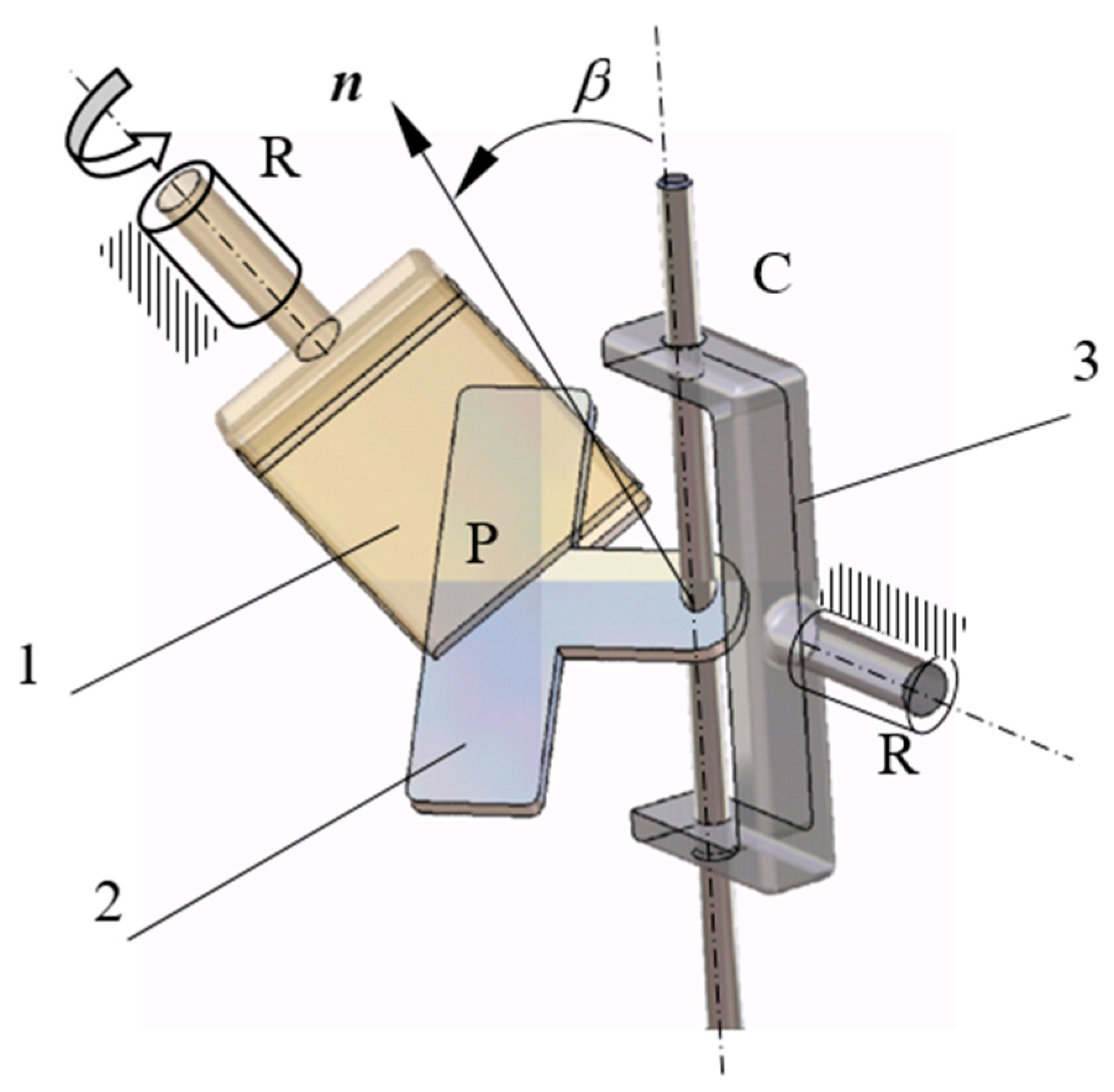
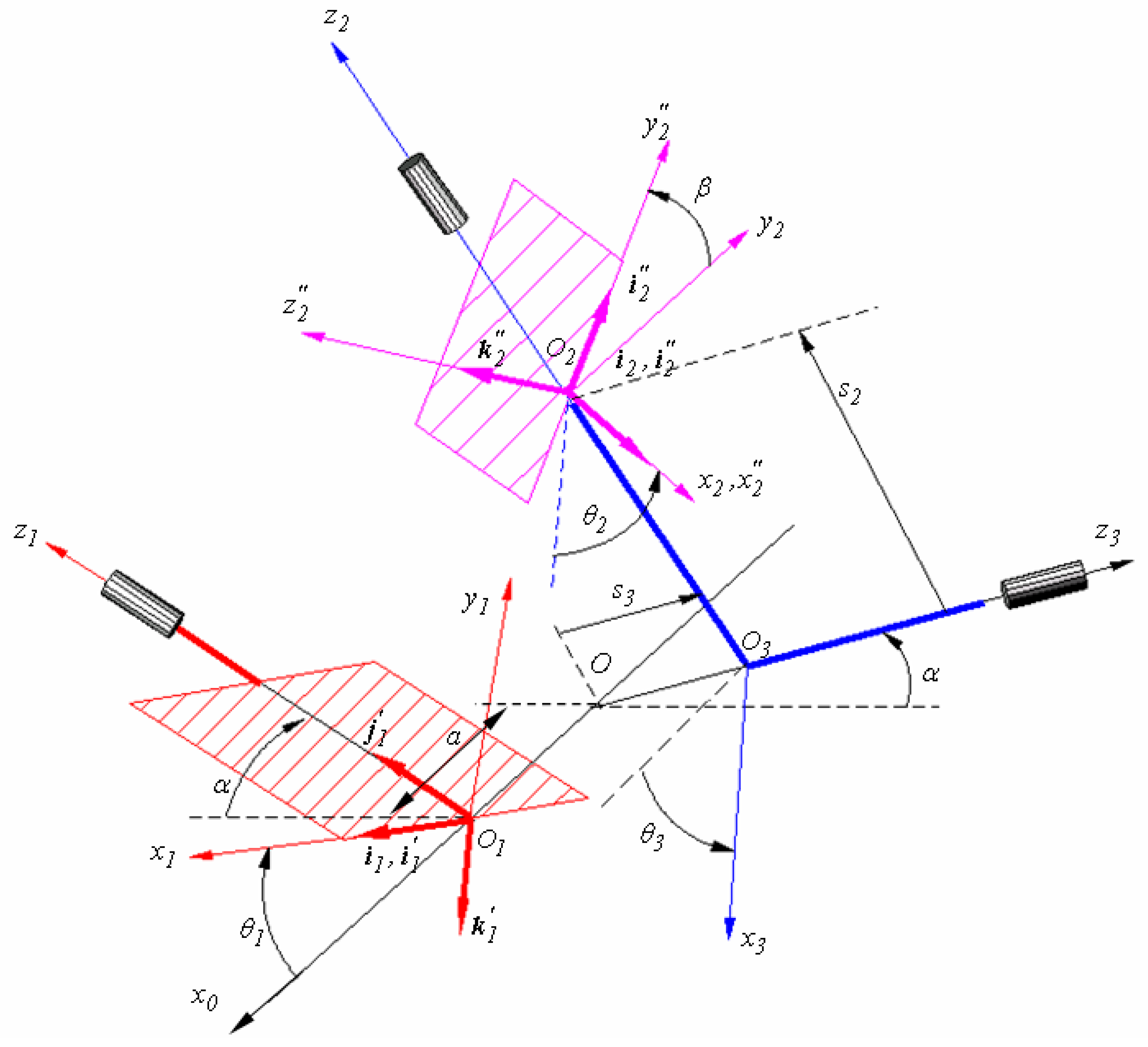
The principal representation of the proposed mechanism, a spatial RPCR mechanism, is shown in Figure 3, where 1 is the driving element, 2 is the intermediate element, 3 is the driven element, and n represents the normal to the contact surface (between the elements 1 and 2) of the plane pair. Figure 4 depicts the coordinate frames attached to the mechanism, which will be further used in solving the problem. The mechanism contains four pairs, that is, two revolute joints, a cylindrical joint, and a planar pair. According to the H-D algorithm, for the cylindrical and revolute joints, the axis of motion is well defined; therefore, the roto-translation with respect to the axis of motion (or the motion in the z-direction) and the roto-translation with respect to the common normal of the two axes of motion (the motion in the x-direction) can be stipulated. For the planar pair, the axis of rotation has a precise direction as the normal to the plane of contact of the elements, but there is no fixed point through which this axis can pass. For this reason, for the kinematic solving of the mechanism, two Cartesian reference systems, x 1 y 1 z 1 and x 2 y 2 z 2 , attached to the driving element and the intermediate element, respectively, will be used for expressing the conditions of the planar pair existence. The directions of the axes of the two frames are in the manner that the axes z 1 and z 2 are normal to the planar surface involved in the formation of the planar joint and the axes x 1 and x 2 are normal to the axes of rotation (the axis of rotation of the driving element and the axis of the cylindrical joint). The right orthogonal frames will be completed by the axes y 1 and y 2 , respectively. The vectors used to express these conditions are described by their projections on the axes of the two reference frames, and from here, the conditions for creating the planar joint should be expressed using the projections of the vectors on the axes of the same frame. The axes of rotation of the driving and driven elements are denoted by z 1 and z 3 , respectively; they are positioned so that their common normal O x 0   is horizontal. Additionally, each of them makes an α angle with the horizontal plane; therefore, the angle between the two axes is ( π 2 α ) . The O point is considered on the common normal, which is obtained by the intersection between the z 3 axis and the common normal. The origin of the coordinate frame ( 1 ) is the point O 1   , which is the intersection between the common normal and the z 1 axis placed at a distance a with respect to the O point. The x 1 axis of the frame ( 1 ) is obtained by trigonometrically rotating the axis O x 0 at θ 1 angle around the axis z 1 .
By rotating the system ( 1 ) about the x 1 axis with the angle π / 2 , the frame ( 1 ) is obtained, with the axis z 1 ( k 1 ) normal to the plane of the plate of the driving element. The x 3 axis of the frame ( 3 ) is obtained via a roto-translation of the axis z 0 , with the angle θ 3 in a trigonometrical direction and s 3 sliding about the z 3 axis. The frame ( 2 ) results from the rotation of the coordinate system (3) with the angle π / 2 around the x 3 axis, followed by a roto-translation of an angle θ 2 (now z 3 takes the position of z 2 axis). After a roto-translation of θ 2 angle and s 2 sliding, the final position of the frame ( 2 ) is obtained. By applying a rotation of β angle to the system ( 2 ) , the system ( 2 ) is obtained, with the axis z 2 (of versor k 2 ) normal to the plane attached to the intermediate element 2.
The vector relations are used in specifying the conditions required for the plane pair construction. Thus, it is necessary that all components of the vectors involved in these relations are expressed with respect to the same frame.
For the present case, McCarthy’s remark [25,26] is followed in order to obtain the simplest relations. To this end, the reference frame must be selected such that the numbers of interposed elements between the reference element and the extreme elements are comparable. Therefore, the coordinate system (3) ,   O x 3 y 3 z 3 ,   in Figure 4 is the logical alternative. The coordinate transformation from one system to another can now be expressed with ease by selecting the previously presented frames and using the homogenous operator method proposed by Hartenberg and Denavit [27]. Applying the methodology from [27], systems of trigonometrical equations result, which solutions are rarely obtained analytically. Uicker [28] proposed a numerical solution of fast convergence by using an iterative methodology. The Hartenberg–Denavit method can be applied for kinematic chains containing non-cylindrical pairs, under the restriction that these pairs should be replaced by kinematic chains formed only by cylindrical, revolute, or prismatic pairs [29].
According to this method, by using a suitable selection of the axes of the coordinate systems attached to the elements of a kinematical chain, the transition from one frame to another can be made by finite successive rotations around the axes z and x of the involved systems. The homogenous operators describing the two displacements are defined by the following matrices:
Z ( θ , s ) = [ cos θ sin θ 0 0 sin θ cos θ 0 0 0 0 1 s 0 0 0 1 ] ,
X ( α , a ) = [ 1 0 0 a 0 cos α sin α 0 0 sin α cos α 0 0 0 0 1 ] ,
where θ ,   s and α , a are the parameters characteristic to the roto-translation about the z and x axes, respectively. The operator that describes the displacement from the element ( p ) to the element ( q ) has the following general form:
T p q = [ R p q d p q [ 0 0 0 ] 1 ] ,
where R p q is an orthogonal matrix which columns are the projections of the versors of the final system ( q ) on the axes of the initial system ( p ) , and d p q is the column matrix having the elements of the projections of the vector O p O q ¯ (links the origins of the two systems) on the axes of the initial system ( p ) . The homogenous operator T 3 1 corresponds to the displacement of the system ( 3 ) over the system ( 1 ) and has the following form:
T 3 1 = Z ( θ 3 , s 3 ) X ( π 2 α , a ) Z ( θ 1 , 0 ) X ( π / 2 , 0 ) .
The homogenous operator for the displacement of the system T 3 2 is as follows:
T 3 2 = X ( π / 2 , 0 ) Z ( θ 2 , s 2 ) X ( β , 0 ) .
To bring the planes attached to the elements 1 and 2 into coincidence, these planes must be parallel and have a common point. The condition of parallelism can be expressed by the stipulation of parallel normals of the planes:
k 1 × k 2 = 0 ,
or an equivalent condition is that the normal of a plane should be perpendicular to two non-collinear vectors from the other plane:
i 1 k 2 = 0 ; .
j 1 k 2 = 0
After the parallelism condition is satisfied, the requirement that makes the planes coincide is
O 1 O 2 ¯ k 2 = 0 .
Equation (9) describes the condition that the points O 1 and O 2 should rest in the plane of symmetry of the planar joint plane that has the normal k 1 = k 2 .

2.2. Finding the Motions from the Pairs of the Mechanism

Developing Equation (4), the next expressions are obtained as follows:
i 1 = [ c o s θ 3 s i n θ 1 s i n θ 3 s i n 2 α s i n θ 1 s i n θ 3 c o s θ 1 c o s θ 3 c o s 2 α s i n θ 1 s i n 2 α s i n θ 1 ] ,
j 1 = [ s i n θ 3 s i n 2 α c o s θ 3 c o s 2 α c o s 2 α ] ,
and the following equation is found by developing Equation (5):
k 2 = [ s i n θ 2 s i n β c o s β c o s θ 2 s i n β ] .
By applying Equations (10)–(12) to Equation (8), the next system is obtained:
{ s i n β c o s θ 1 s i n θ 2 c o s θ 3 c o s 2 α s i n θ 1 s i n θ 2 s i n θ 3 + c o s β c o s θ 1 s i n θ 3 + c o s 2 α c o s β s i n θ 1 c o s θ 3 s i n 2 α s i n β s i n θ 1 c o s θ 2 = 0 s i n 2 α c o s β c o s θ 3 s i n 2 α s i n β s i n θ 2 s i n θ 3 + c o s 2 α s i n β c o s θ 2 = 0
The angles θ 2 and θ 3 are the unknowns of the system (13). Solving the system in this form may give incorrect results since the function a t a n ( x ) occurs in the solution of the system. To avoid this inconvenience, the following equations are added to the system (13):
c o s 2 θ 2 + s i n 2 θ 2 = 1 ,
c o s 2 θ 3 + s i n 2 θ 3 = 1 .

2.3. Solving the Equations for Finding the Positional Parameters of the Mechanism

Equations (13)–(15) can now be regarded as a system of unknown s i n   θ 2 , c o s   θ 2 , s i n   θ 3 ,   and c o s   θ 3 ; the angles θ 2 and θ 3 can be found using the functions a t a n 2 ( y , x ) and a n g l e ( x , y ) , which allow for the unequivocal determination of the polar angle of a point of ( x , y ) coordinates. Using the function a t a n ( y / x ) to obtain the polar angle leads to confusions because the same result is obtained for the symmetrical points with respect to the origin. Subsequently, the system (13) is considered as having unknowns c o s θ 3 and s i n θ 3 and has the following solutions:
{ c o s θ 3 = c o s θ 2 s i n 2 β s i n θ 1 s i n θ 2 c o s 2 α s i n β c o s β c o s θ 1 s i n 2 α c o s θ 1 ( 1 s i n 2 β c o s 2 θ 2 ) s i n θ 3 = c o s θ 2 s i n 2 β c o s θ 1 s i n θ 2 + s i n β c o s β s i n θ 1 s i n 2 α c o s θ 1 ( 1 s i n 2 β c o s 2 θ 2 )
which are obtained using the Mathcad software.
Replacing these solutions into Equation (15), the next equation is obtained:
s i n 2 2 α c o s 2 θ 1 s i n 2 β c o s 2 θ 2 = 0 .
In an analogous manner, the system (13) is solved with respect to c o s θ 2 and s i n θ 2 , and it is obtained as follows:
{ c o s θ 2 = s i n 2 α c o s β c o s θ 1 s i n β c o s 2 α c o s θ 1 c o s θ 3 s i n β s i n θ 1 s i n θ 3 s i n θ 2 = c o s β s i n θ 1 c o s θ 3 c o s 2 α c o s θ 1 s i n θ 3 s i n β c o s 2 α c o s θ 1 c o s θ 3 s i n β s i n θ 1 s i n θ 3
The solutions (18) are replaced into Equation (15) and lead to the following equation of θ 3 as the unknown:
( c o s 2 2 α c o s 2 θ 1 s i n 2 θ 1 ) c o s 2 θ 3 2 c o s 2 α c o s θ 1 s i n θ 1 c o s θ 3 s i n θ 3 + s i n 2 β c o s 2 θ 1 = 0 .
It is obvious that Equation (17) is simpler to solve than Equation (19). To this end, the equation is first regarded as a quadratic equation of unknown c o s θ 2 , where the final solutions are as follows:
θ 2 ( 1 ) = a c o s s i n 2 α c o s θ 1 s i n β ; θ 2 ( 2 ) = π a c o s s i n 2 α c o s θ 1 s i n β .
Equation (20) presents the following significant consequences:
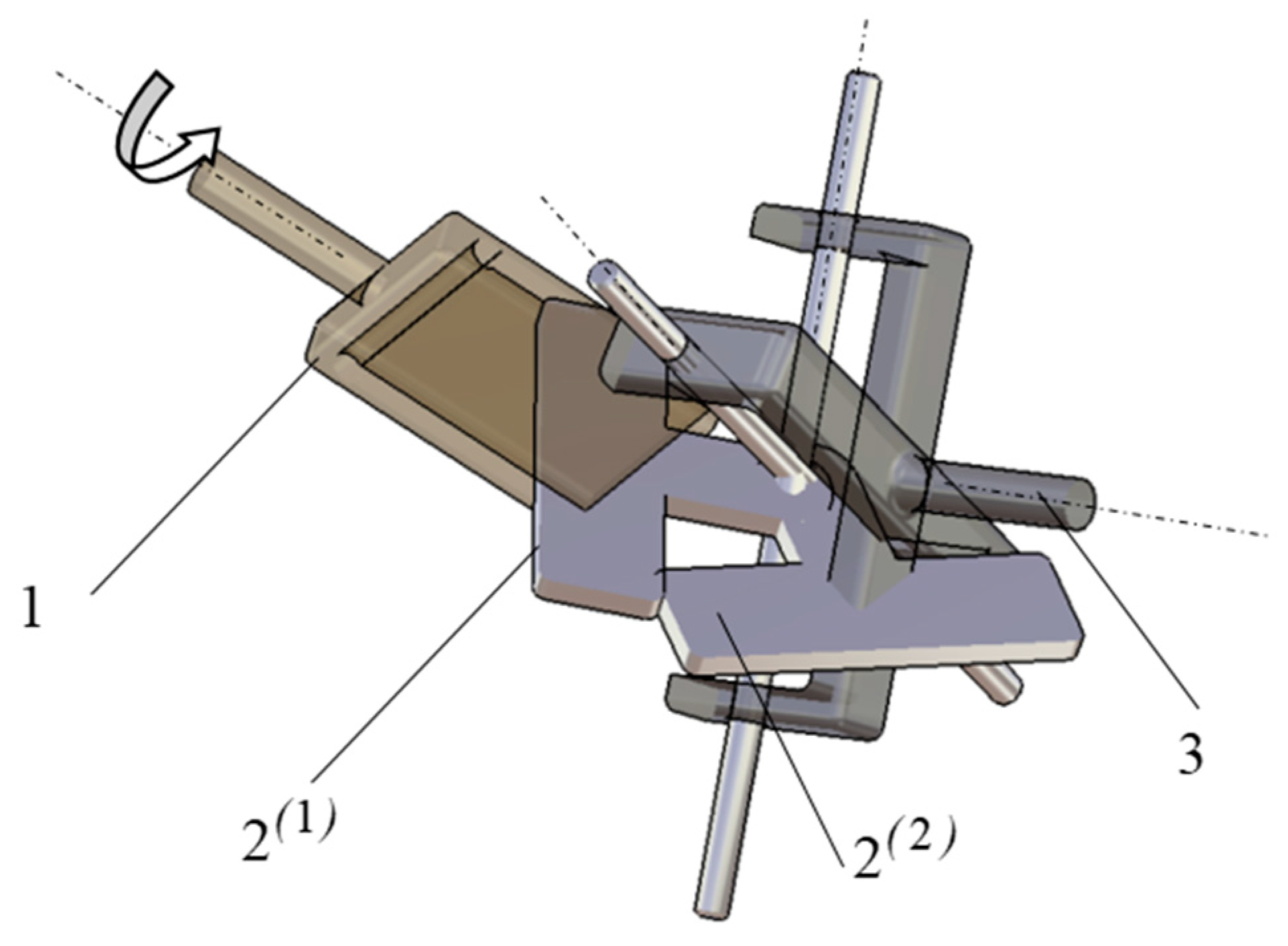
  • The existence of the two solutions of Equation (18) shows that for a given position of the driving element, there are two positions of the intermediate element. This fact is not anticipated initially, and the two assemblage positions are presented in Figure 5.
  • In Equation (20), the ratio existence requires that
β 0 ,
while for the existence of the function a c o s , it is necessary that
s i n 2 α / s i n β 1 , α < β / 2 .
Additionally, it is necessary to avoid nil denominators of the fractions from Equation (16) as follows:
1 s i n 2 β c o s 2 θ 2 0
The condition (23) will always be fulfilled if
β < π / 2 .
Equations (21) and (24) describe two limit constructive situations of the mechanism. In the first case when β = 0 , the plane of element 2 contains the axis of the cylindrical pair; therefore, when element 1 is immobile, the intermediate element does not have a well-established position and can slide along the axis of the cylindrical pair.
For the second case when β = π / 2 , the plane of the element is normal to the axis of the cylindrical pair. The element can perform a passive rotation around the axis of the cylindrical pair, but it cannot glide along this axis. Both cases represent boundary situations when the cylindrical pair behaves as a fifth-class pair rather than a fourth-class one, resulting in the blocking of the mechanism. Equation (22) ensures the existence of an actual solution of the system (13) for any position of the driving element and is, thus, the condition of crank existence of the mechanism.
In order to find the angle θ 3 , Equation (19) is used, but a new variable is introduced, the angle 2 θ 3 ; thus, a linear equation in cos ( 2 θ 3 ) and sin ( 2 θ 3 ) is obtained, having the solution as a function of a t a n ( x ) :
θ 3 ( 1 , 2 ) = a t a n [ ± cos 2 α cos θ 1 s i n θ 1 + s i n 2 θ 1 + c o s 2 2 α c o s 2 θ 1 c o s 2 β ] s i n 2 β c o s 2 θ 1 .
To avoid these difficulties, the two values of the angle θ 2 from Equation (20) are successively introduced in Equation (16). Then, one of the functions, a n g l e ( x , y ) or a t a n 2 ( y , x ) , is applied as follows [30]:
θ 2 ( 1 , 2 ) = a n g l e { cos [ θ 3 ( θ 2 ( 1 , 2 ) ) , θ 1 ] , sin [ θ 3 ( θ 2 ( 1 , 2 ) ) , θ 1 ] } .
The above angle(x,y) function is the function which returns the angle between the positive direction of Ox axis and the position vector of the point M(x,y) [31].
Equation (8) must now be applied to fulfil the condition of coincidence of the two planes. The projections of the vector O 1 O 2 ¯ in the frame ( 3 ) are necessary:
O 1 O 2 ¯ = ( T 3 2 T 3 1 ) [ 0 0 0 1 ] T ,
and the explicit relation is
O 1 O 2 ¯ = [ a · c o s θ 3 s 2 a · s i n θ 3 s 3 ] T .
After applying Equation (8), the translation s 2 from the cylindrical pair may now be determined as follows:
s 2 = a · s i n θ 1 + s 3 s i n 2 α c o s θ 1 c o s 2 α c o s θ 1 c o s θ 3 s i n θ 1 s i n θ 3 .

3. Results and Discussion

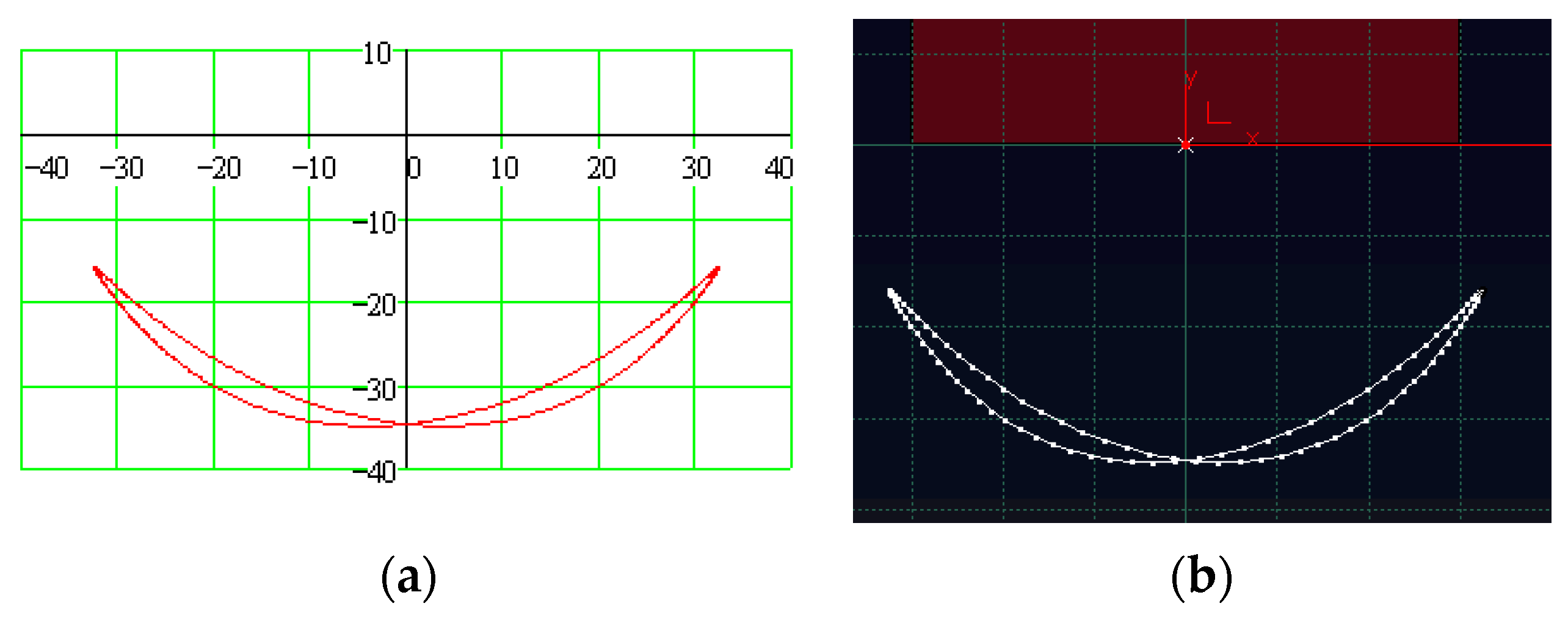
The analytical results are corroborated by modeling the mechanism using the CATIA simulation software. Comparison was made between the analytical results and the numerical results obtained using the software for a series of parameters. A first validation refers to the trajectory of the point O 2 :
x O 2 = O 1 O 2 ¯ i 1 ; y O 2 = O 1 O 2 ¯ j 1 ,
on the plane ( x 1 y 1 ) attached to element 1, which was obtained both via the analytical method and the simulation software. The comparison between the trajectories obtained using the analytical solutions presented in the work and the numerical solutions provided by the software are presented in Figure 6. The numerical simulation in Figure 6b was obtained using the DMU Kinematics module of CATIA.
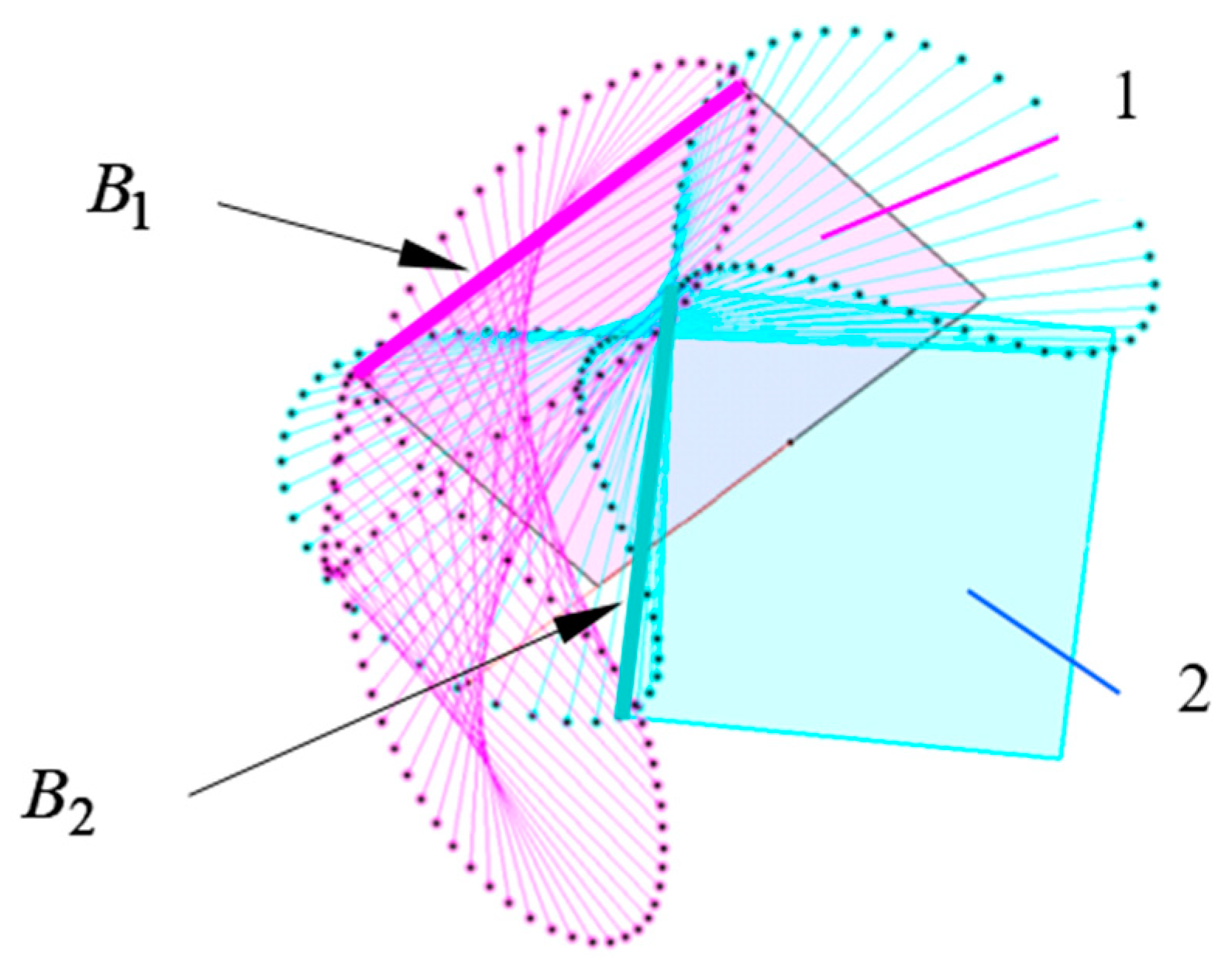
Another helpful comparison refers to the geometrical loci of the point of a line segment B 2 from the plane attached to element 1 with respect to the plane attached to element 2, and of a line segment B 1 attached to element 1 in the plane attached to element 2 (Figure 7, also obtained in CATIA). From Equations (4) and (5), we find the projections of the versors of the systems ( 1 ) ,   i 1 , j 1 , k 1 and ( 2 ) : , i 2 , j 2 k 2 , respectively, on the axes of the frame ( 3 ) .
With these projections known, the angle of rotation between the two plates can be found:
ϕ 21 ( θ 1 ) = a n g l e [ i 2 ( θ 1 ) i 1 ( θ 1 ) , j 2 ( θ 1 ) i 1 ( θ 1 ) ] ,
and
ϕ 12 ( θ 1 ) = a n g l e [ i 1 ( θ 1 ) i 2 ( θ 1 ) , j 1 ( θ 1 ) i 2 ( θ 1 ) ] .
By applying the relations of transformation for the plane coordinates [25], it results in the following:
[ x 1 y 1 1 ] = [ x O 2 y O 2 1 ] + [ c o s ϕ 12 s i n ϕ 12 0 s i n ϕ 12 c o s ϕ 12 0 0 0 1 ] [ x 2 y 2 1 ] ,
where x O 2   and   y O 2 are found using Equation (30), and x 2     and   y 2 are the known coordinates of a fixed point in the frame ( 2 ) . In a similar manner but in reverse order, we find the geometrical loci of a line segment B 1 from the plane attached to element 1 with respect to the plane fixed to element 2. The positions occupied by a line segment fixed to element 2 in this plane are compared in Figure 8.
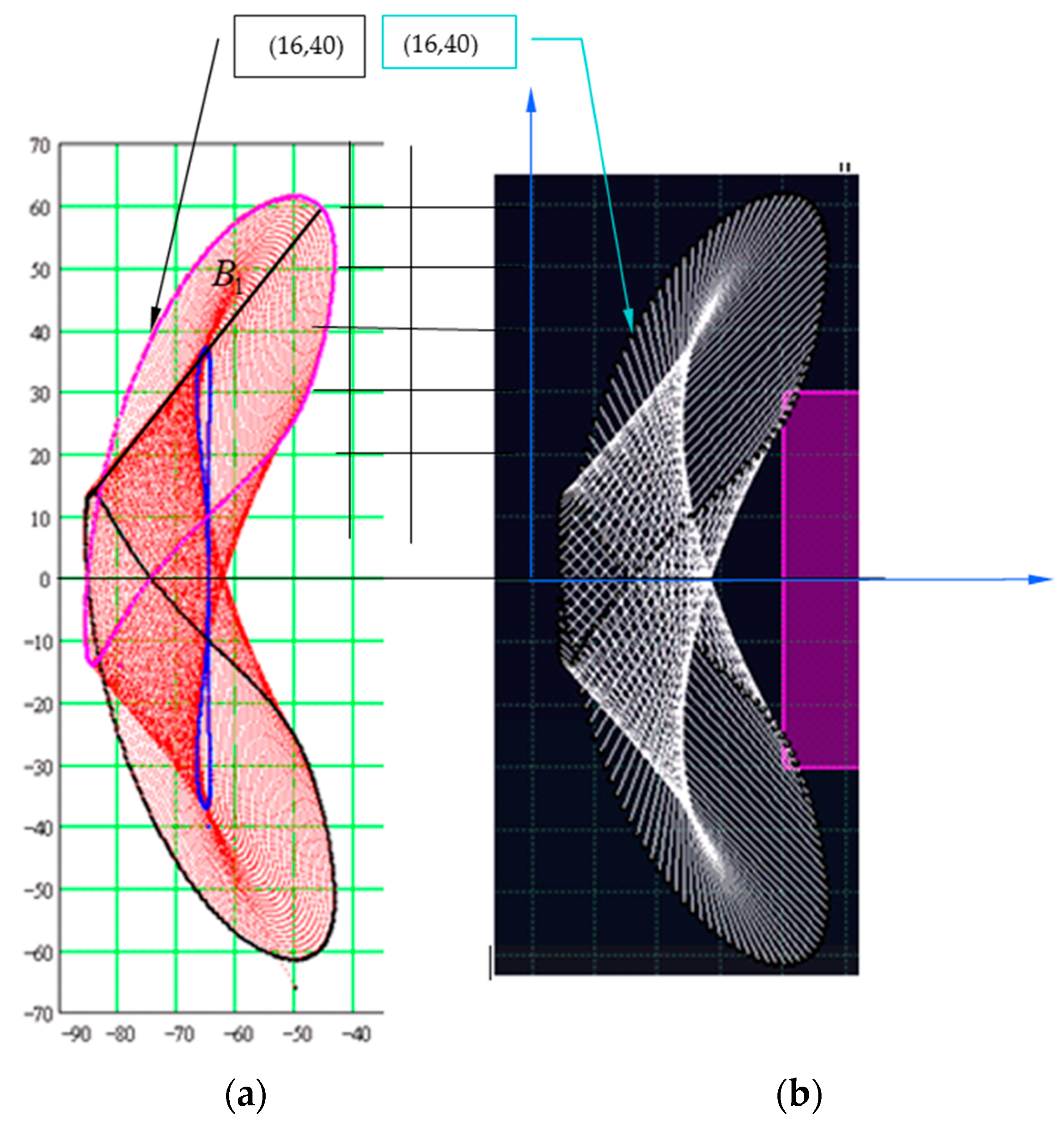
The successive positions (in the plane of plate 2) of a line segment fixed to element 1 are presented in Figure 9. Gridlines are evidenced on both images (for analytical results from Mathcad and numerical results from CATIA), and these permit the precise identification of the coordinates of any point from the figures. The concordance between the coordinates of similar points from the two figures is a quantitative procedure for the validation of the analytical results. Figure 9 exemplifies a numerical comparison of coordinates of similar points.
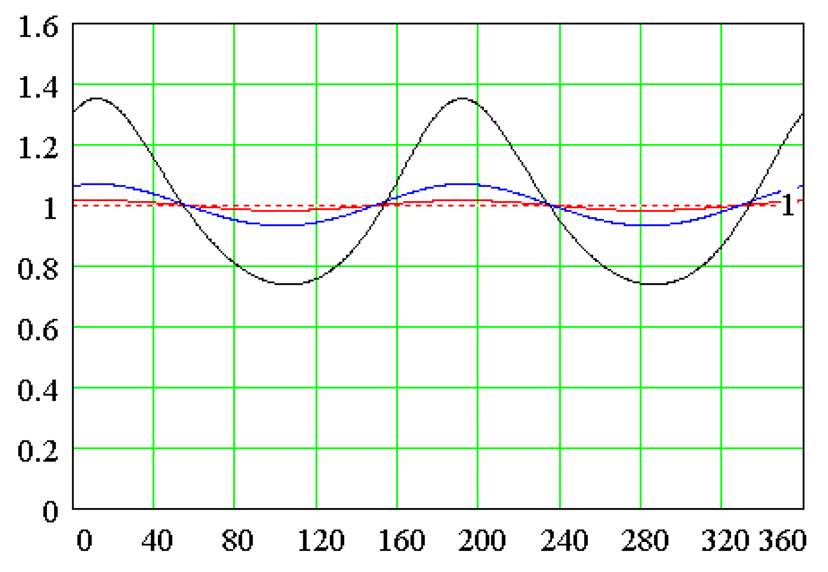
A significant parameter is the transmission ratio ω 3 / ω 1 , which is the ratio between the angular velocities of the driven and driving shafts.
In Figure 10, there are traced plots for three values of the angle α ( π / 36 ; π / 18 ; and   π / 9 ), and it can be observed that for α angles smaller than π / 36 (the red plot in Figure 10), the ratio is quasi-unity. This feature can be applied to the parallel shafts with high angular tolerances where the Cardan joint cannot be employed due to the strict requirement of intersection of axes. Beside this advantage, the solution is also inexpensive since the parts that materialize elements 1, 2, and 3 from the design are highly technological and the assemblage is basic.
The key result resides in the simple design and high durability. The constructive simplicity is based on the fact that a single middle part connects the two shafts. The decisive modification, when related to other solutions, consists of the presence of the planar joint in the structure of the mechanism. The weak point of the proposed mechanism is the circumstance that the sliding friction from the planar pair cannot be replaced by rolling friction, and, thus, the efficiency of transmission is inferior than for mechanisms which contain only revolute pairs.

4. Conclusions

This paper presents a new solution for coupling two shafts with crossed axes and the analytical solutions for the motion from the pairs of the mechanism. The coupling is achieved via an intermediate element that forms a planar pair with one shaft and a cylindrical pair with the other shaft, resulting in a RPCR type of mechanism.
The existence of the planar pair in the structure of the kinematical chain renders the H-D method unsuitable. The condition equations (constitutive equations) of the planar pair are required in order to obtain the analytical solutions for the motion of the mechanism.
The coordinate frames are defined, as well as the method of choosing the reference system. For this system, the expressions of the condition equations of the planar pair are conducted with the simplest system of scalar equations. This is followed by presenting the solution to the system, specifying ways to prevent confusion generated by the use of certain multiform functions.
The conditions of existence of the pairs’ expression of motion functions allow the finding of the constructive parameter values for which uncontrolled motions are probable in some pairs. Furthermore, the conditions are also used to identify the restrictions imposed to the constructive parameters, which ensure the complete rotation of the driving element (the existence of the crank).
The analytical expressions obtained are corroborated by the results obtained using a CAD model of the mechanism. The validation of the relations was made by comparing the trajectories generated by points from one of the elements of the planar pair with respect to the other element. The full concordance between the analytical and numerical results proves the accuracy of the analytical relations.
The proposed coupling solution is robust and reliable, considering that only lower pairs are present in the structure of the mechanism. Additionally, by changing the angle between the axis of the cylindrical pair and the normal to the plane of the planar pair, a straightforward adjustment of the motion of the driven shaft is allowed.
Another major result of the work is that, with the obtained analytical solution, the dimensional synthesis is simple and permits dimensional optimization.

Author Contributions

Conceptualization, S.A. and M.-C.C.; methodology, S.A. and F.-C.C.; software, I.-C.R. and T.-M.C.; validation, S.A. and I.-C.R.; writing—original draft preparation, F.-C.C. and T.-M.C.; writing—review and editing, S.A. and M.-C.C. All authors have contributed equally to the work. All authors have read and agreed to the published version of the manuscript.

Funding

This research received no external funding.

Data Availability Statement

Not applicable.

Conflicts of Interest

The authors declare no conflict of interest.

References

  1. Denavit, J.; Hartenberg, R.S. A kinematic notation for lower-pair mechanisms based on matrices. J. Appl. Mech. 1955, 22, 215–221. [Google Scholar] [CrossRef]
  2. Barbin, E.; Menghini, M.; Volkert, K. Descriptive Geometry, the Spread of a Polytechnic Art—The Legacy of Gaspard Monge; Springer Nature: Cham, Switzerland, 2019; pp. 3–18. [Google Scholar]
  3. Tsai, L.-W. Mechanism Design: Enumeration of Kinematic Structures According to Function; CRC Press: Boca Raton, FL, USA, 2000; 328p. [Google Scholar]
  4. Johnson, K.L. Contact Mechanics; Cambridge University Press: Cambridge, UK, 1985; pp. 84–106. [Google Scholar] [CrossRef]
  5. Hills, D.A.; Nowell, D.; Sackfield, A. Mechanics of Elastic Contacts; Elsevier Butterworth-Heinemann: Oxford, UK, 1993; pp. 198–226. [Google Scholar]
  6. Gladwel, G.M.L. Contact Problems in the Classical Theory of Elasticity; Sijthoff & Noordhoff: The Hague, The Netherlands, 1980; 716p. [Google Scholar]
  7. Alaci, S.; Ciornei, F.; Filote, C. Considerations upon a new tripod joint solution. Mechanika 2013, 19, 567–574. [Google Scholar] [CrossRef]
  8. Urbinati, F.; Pennestrì, E. Kinematic and Dynamic Analyses of the Tripode Joint. Multibody Syst. Dyn. 1998, 2, 355–367. [Google Scholar] [CrossRef]
  9. Wang, X.F.; Chang, D.G.; Wang, J.Z. Kinematic investigation of tripod sliding universal joints based on coordinate transformation. Multibody Syst. Dyn. 2009, 22, 97–113. [Google Scholar] [CrossRef]
  10. Phillips, J. Freedom in Machinery; Cambridge University Press: Cambridge, UK, 2007; 448p. [Google Scholar]
  11. Alaci, S.; Buium, F.; Ciornei, F.-C.; Dobincă, D.-I. Tetrapod coupling. Mech. Mach. Sci. 2018, 57, 349–356. [Google Scholar] [CrossRef]
  12. Yi, L.; Leinonen, T. On the Dimensional Synthesis of Spatial Four-and Five-Bar Linkage. In Romansy 14: Theory and Practice of Robots and Manipulators, Proceedings of the Fourteenth CISM-IFToMM Symposium; Bianchi, G., Guinot, J.-C., Rzymkowski, C., Eds.; Springer: Vienna, Austria, 2002; pp. 407–419. [Google Scholar]
  13. Watanabe, K.; Sekine, T.; Nango, J. Kinematic Analysis of RSCR Spatial Four-Link Mechanisms. Trans. Jpn. Soc. Mech. Eng. Ser. C 1997, 63, 2482–2489. [Google Scholar] [CrossRef]
  14. Lenarčič, J.; Bruno Siciliano, B. Advances in Robot Kinematics; Springer: Cham, Switzerland, 2020; pp. 1–6; 98–108. [Google Scholar] [CrossRef]
  15. Altuzarra, O.; Kecskeméthy, A. Advances in Robot Kinematics; Springer: Cham, Switzerland, 2022; pp. 30–38. [Google Scholar] [CrossRef]
  16. Tsai, C.Y.; Lin, P.D. The mathematical models of the basic entities of multi-axis serial orthogonal machine tools using a modified Denavit–Hartenberg notation. Int. J. Adv. Manuf. Technol. 2009, 42, 1016–1024. [Google Scholar] [CrossRef]
  17. Lee, R.S.; Lin, Y.H. Development of universal environment for constructing 5-axis virtual machine tool based on modified D–H notation and OpenGL. Robot. Comput.-Integr. Manuf. 2010, 26, 253–262. [Google Scholar] [CrossRef]
  18. Benignus, C.; Buschner, P.; Meier, M.K.; Wilken, F.; Rieger, J.; Beckmann, J. Patient Specific Instruments and Patient Individual Implants—A Narrative Review. J. Pers. Med. 2023, 13, 426. [Google Scholar] [CrossRef] [PubMed]
  19. Vorro, J.; Bush, T.R.; Rutledge, B.; Li, M. Kinematic measures during a clinical diagnostic technique for human neck disorder: Inter- and intraexaminer comparisons. Biomed. Res. Int. 2013, 2013, 950719. [Google Scholar] [CrossRef] [PubMed]
  20. Greco, C.; Weerakkody, T.H.; Cichella, V.; Pagnotta, L.; Lamuta, C. Lightweight Bioinspired Exoskeleton for Wrist Rehabilitation Powered by Twisted and Coiled Artificial Muscles. Robotics 2023, 12, 27. [Google Scholar] [CrossRef]
  21. Dimentberg, F.M. The Screw Calculus and Its Applications in Mechanics; Foreign Technology Division translation FTD-HT-23-1965; US Department of Commerce: Washington, DC, USA, 1969; pp. 1632–1667.
  22. Hunt, K.H. Kinematic Geometry of Mechanisms; Oxford University Press: Oxford, UK, 1990; pp. 30–51. [Google Scholar]
  23. Davidson, J.K.; Hunt, K.H. Robots and Screw Theory: Applications of Kinematics and Statics to Robotics; Oxford University Press Inc.: New York, NY, USA, 2004; pp. 59–94. [Google Scholar]
  24. Angeles, J. Spatial Kinematic Chains: Analysis–Synthesis–Optimization; Springer: Berlin/Heidelberg, Germany, 1982; pp. 189–218. [Google Scholar]
  25. McCarthy, J.M.; Soh, G.S. Geometric Design of Linkages; Springer: Berlin/Heidelberg, Germany, 2010; pp. 253–279. [Google Scholar]
  26. McCarthy, J.M. Introduction in Theoretical Kinematics, 3rd ed.; MIT Press: Boston, MA, USA, 2018; pp. 103–108. [Google Scholar]
  27. Hartenberg, J.R.; Denavit, J. Kinematic Synthesis of Linkages, 1st ed.; McGraw-Hill Inc.: New York, NY, USA, 1964; pp. 343–368. [Google Scholar]
  28. Uicker, J.J., Jr.; Denavit, J.; Hartenberg, R.S. An Iterative Method for the Displacement Analysis of Spatial Mechanisms. J. Appl. Mech. 1964, 31, 309–314. [Google Scholar] [CrossRef]
  29. Alaci, S.; Pentiuc, R.D.; Ciornei, F.C.; Buium, F.; Rusu, O.T. Kinematics analysis of the swash plate mechanism. IOP MSE 2019, 568, 012017. [Google Scholar]
  30. Yoshikawa, T. Foundations of Robotics: Analysis and Control; MIT Press: Boston, MA, USA, 2003; pp. 259–262. [Google Scholar]
  31. Maxfield, B. Engineering with Mathcad; Elsevier Butterworth-Heinemann: Oxford, UK, 2006; pp. 287–289. [Google Scholar]
Figure 1. Cardan coupling.
Axioms 12 00357 g001
Figure 2. Double Cardan joint.
Axioms 12 00357 g002
Figure 3. The spatial RPCR mechanism.
Axioms 12 00357 g003
Figure 4. Cartesian reference systems: x 1 y 1 z 1 attached to the driving element, x 2 y 2 z 2 attached to the intermediate element, and x 3 y 3 z 3 attached to the driven element.
Axioms 12 00357 g004
Figure 5. The assemblage possibilities of the mechanism.
Axioms 12 00357 g005
Figure 6. The trajectory of the point O 2 in the frame attached to the driving element: (a) analytical solution and (b) numerical simulation.
Axioms 12 00357 g006
Figure 7. The positions of a line segment attached to a plate with respect to the other one.
Axioms 12 00357 g007
Figure 8. The geometrical loci of a straight line (B2) attached to element 2 with respect to element 1: (a) analytical and (b) numerical results.
Axioms 12 00357 g008
Figure 9. The geometrical loci of a straight line (B1) attached to element 1, with respect to element 2: (a) analytical and (b) numerical results.
Axioms 12 00357 g009
Figure 10. The plots of the transmission ratio ω 3 / ω 1 for different values of the angle between axes: π / 36 (red); π / 18 (blue); and π / 9 (black).
Axioms 12 00357 g010
Disclaimer/Publisher’s Note: The statements, opinions and data contained in all publications are solely those of the individual author(s) and contributor(s) and not of MDPI and/or the editor(s). MDPI and/or the editor(s) disclaim responsibility for any injury to people or property resulting from any ideas, methods, instructions or products referred to in the content.