Review

Power Conversion Techniques Using Multi-Phase Transformer: Configurations, Applications, Issues and Recommendations

by
Md Tabrez
1,2,
Pradip Kumar Sadhu
1,
Molla Shahadat Hossain Lipu
3,4,*,
Atif Iqbal
5,
Mohammed Aslam Husain
6,* and
Shaheer Ansari
3
1
Department of Electrical Engineering, IIT (ISM), Dhanbad 826004, India
2
Electrical and Electronics Engineering Department, Motihari College of Engineering, Bihar 845401, India
3
Department of Electrical, Electronic and Systems Engineering, Universiti Kebangsaan Malaysia, Bangi 43600, Selangor, Malaysia
4
Centre for Automotive Research (CAR), Universiti Kebangsaan Malaysia, Bangi 43600, Selangor, Malaysia
5
Department of Electrical Engineering, Qatar University, Doha 2713, Qatar
6
Department of Electrical Engineering, Rajkiya Engineering College, Ambedkar Nagar, Uttar Pradesh 224122, India
*
Authors to whom correspondence should be addressed.
Machines 2022, 10(1), 13; https://doi.org/10.3390/machines10010013
Submission received: 21 October 2021 / Revised: 11 December 2021 / Accepted: 14 December 2021 / Published: 23 December 2021
(This article belongs to the Special Issue Innovative Applications of Multiphase Machines)

Abstract

:
Recently, the superiority of multi-phase systems in comparison to three-phase energy systems has been demonstrated with regards to power generation, transmission, distribution, and utilization in particular. Generally, two techniques, specifically semiconductor converter and special transformers (static and passive transformation) have been commonly employed for power generation by utilizing multi-phase systems from the available three-phase power system. The generation of multi-phase power at a fixed frequency by utilizing the static transformation method presents certain advantages compared to semiconductor converters such as reliability, cost-effectiveness, efficiency, and lower total harmonics distortion (THD). Multi-phase transformers are essential to evaluate the parameters of a multi-phase motor, as they require a multi-phase signal that is pure sine wave in nature. However, multi-phase transformers are not suitable for variable frequency applications. Moreover, they have shortcomings with regard to impedance mismatching, the unequal number of turns which lead to inaccurate results in per phase equivalent circuits, which results in an imbalance output in phase voltages and currents. Therefore, this paper aims to investigate multi-phase power transformation from a three-phase system and examine the different static multi-phase transformation techniques. In line with this matter, this study outlines various theories and configurations of transformers, including three-phase to five-, seven-, eleven-, and thirteen-phase transformers. Moreover, the review discusses impedance mismatching, voltage unbalance, and per phase equivalent circuit modeling and fault analysis in multi-phase systems. Moreover, various artificial intelligence-based optimization techniques such as particle swarm optimization (PSO) and the genetic algorithm (GA) are explored to address various existing issues. Finally, the review delivers effective future suggestions that would serve as valuable opportunities, guidelines, and directions for power engineers, industries, and decision-makers to further research on multi-phase transformer improvements towards sustainable operation and management.

1. Introduction

The multi-phase-based power system has various advantages over a three-phase-based power system such as the capability to handle a higher magnitude of power, better fault tolerance and low harmonics. Furthermore, it provides numerous benefits such as reduced amplitude and rotor current harmonics, increased torque pulsation frequency, reduction in current per phase without increasing the per phase voltage, lowered DC-link current ripples, more fault tolerance, and a reduced power switch rating. By expanding the number of phases, it is possible to increase the power or torque per root mean square (RMS) ampere for a similar volume machine. The crudest records of multi-phase systems date back to 23 February 1894, when S. P. Thompson delivered an article in front of the Royal Institution [1]. The first application of multi-phase variable speed drives was studied in the late 1960s, where the inverter-fed AC drives were in the underlying advancement phase [1]. The comparative analysis between a three-phase machine and a multi-phase machine is presented in Table 1.
From Table 1, it is seen that a multiple-phase transformer has several advantages, including low magnetic interference, low phase-to-phase voltage at rated power, and continuous operation after fault occurrence with reduced capacity. There are some disadvantages associated with the multi-phase systems which pose challenges to researchers and create new opportunities for further research. These are:
(a)
Complex design procedures.
Multi-phase transformer design is not as straightforward as single-phase and three-phase transformer design due to multiple windings in each phase. Appropriate turn ratios and proper connection of multiple windings are vital in the creation of phasors of the multi-phase. Therefore, human expertise and knowledge are essential for designing multi-phase transformers.
(b)
Unequal series parameters.
It is worth mentioning that the secondary of a multi-phase transformer is made from multiple windings with an unequal number of turns. This creates unequal series impedance of the secondary side which, in turn, creates unbalances in the output voltages. Hence, appropriate phase balancing is required to study the per phase equivalent circuit to achieve accurate outcomes.
(c)
Lack of fault and unbalancing studies.
To find the sequence components of an unbalanced multi-phase voltage or current, the Fortescue theorem is necessary to investigate faults and any unbalancing of a multi-phase system. Unfortunately, these kinds of studies are very limited in the literature. Therefore, further studies are needed on fault and unbalancing studies.
(d)
Higher cost.
The cost of a multi-phase transformer is higher due to larger copper requirements and design complexity. Thus, further exploration is necessary to reduce its price.
The utilization of a multi-phase system is observed in electric power generation, transmission, and utilization [2]. The exploration of multi-phase generators began recently, and only a few references are available in the literature [3]. The usage of phases in multi-phase machines is prominent in drive applications, making a beeline for an expanded enthusiasm for multistage AC drive applications, particularly related to traction [2], electric vehicles (EVs) and hybrid electric vehicles (HEVs), and electric ship propulsion system [3,4]. An increase in the phases may improve the effectiveness, robustness, and reliability at a cost of the increased complexity of the multi-phase converter and other equipment [5,6,7]. Multi-phase transmission lines can furnish a similar power handling capability with a lower phase-to-phase voltage and smaller, compact towers than standard double circuit three-phase lines [8]. The geometry of the multi-phase compact towers may help in the decrease in magnetic fields [8]. The multi-phase power system in some instances is seen to be more efficient compared to a three-phase system, as it utilizes less conductor material and short height towers to transmit the power than a comparable single-phase or two-phase system at a similar voltage magnitude.
The three-phase alternating current (AC), two-phase AC, multi-phase voltage source inverter (VSI) can be applied for carrying out static multi-phase transformation. With regards to industrial application, the power delivered to the machine can be carried out by AC–DC–AC transformation, where the input three-phase AC is converted to multi-phase AC. Studies demonstrate that the employment of special transformers can be utilized for directly converting a three-phase or two-phase AC into multi-phase AC [5,6,7,8]. In recent times, the applications of direct AC–AC matrix converters have been increasing compared to the traditional AC–DC–AC converters due to their various advantages [9,10,11,12,13]. The various benefits of AC–AC matrix converters include operating at unity power factor irrespective of the loading condition and their requirement for minimum energy storage [4]. Nonetheless, matrix converters suffer from several disadvantages regarding limited voltage transfer ratio and require semiconductor devices in larger numbers [4]. Multi-phase research, especially on multi-phase VSI, multi-phase drives, and multi-phase induction machines, is what has been investigated so far. Recently, controlling a five-phase induction machine with a three-phase inverter via a three-to-five phase transformer was explored [14]. A method for reducing the common-mode voltage in a seven-phase brushless DC motor (BLDCM) application is described in [15]. Recent advances in nine-phase applications include the development of an improved and efficient nine-phase three-level [16] and nine-phase five-leg inverter [17]. The optimal design of the slots per pole for multi-phase machines of a prime number of phases is presented in [18]. The introduction of static phase conversion dates back to 1894 where S.P. Thompson delivered an article in front of the Royal Institution, and on the first of March around the same time, C.F. Scott delivered his noteworthy research work in front of the National Electric Light Association in Washington [1]. In 1895, M. Leblance employed an alternate plan including a single three-limbed transformer for a close connection between two-phase alternators and three-phase transmission lines [1]. Numerous studies have explored the applications of five-phase and seven-phase VSI in the literature. Studies on five- and seven-phase VSI are found abundantly in the literature. The multi-phase transformer with a number of phases in multiples of three or even-phase are much more explored in the literature. Unfortunately, prime-phase (five-, seven-phase, etc.) multi-phase transformers are the least discussed in the literature. Although the technology of the three-phase to six-, nine-, and twelve-phase static transformation is straightforward and mature enough, little work has been carried out for prime numbers of phases such as five, seven, eleven, or thirteen. This paper addresses the extensive review of the available literature and enumerates the potential research scope for a three-phase to an n(prime)-phase system [7].
This review paper showcases the new research directions in the static multi-phase transformation to fill the research gaps in the existing works in this field. This review work deals with the following contributions in the field of static multi-phase transformation:
  • A simplified and standard procedure to calculate the number of turns of primary and secondary windings of the multi-phase transformer is discussed.
  • A three-phase to five-, seven-, eleven-, thirteen-phase transformer is discussed.
  • Key issues and challenges of multi-phase power generated by three-phase to the multi-phase transformer are highlighted, discussed and accordingly, a few effective solutions are proposed.
  • Some constructive recommendations are given at the end that open new research directions in the field of the multi-phase transformer.
This paper is divided into five sections. Section 1 is the previously discussed introduction. Section 2 deals with the different theories of static phase transformation available in the literature and its application with three-phase to the five-phase transformer, three-phase to seven-phase transformation, and other multi-phase transformers. Section 3 deals with the potential and available application of multi-phase transformers. Issues and challenges associated with a multi-phase transformer are discussed in Section 4. The validation and experimental results are highlighted in Section 5. Finally, the conclusion and recommendations are presented in Section 6.

2. Configuration of Phase Transformation Techniques

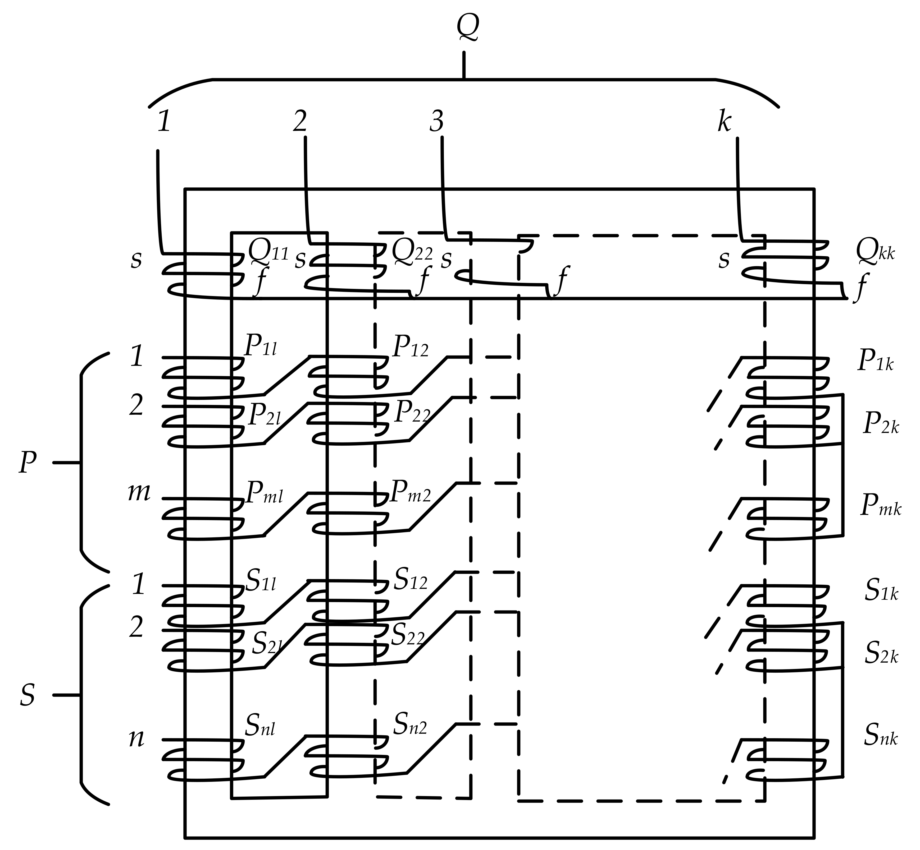
2.1. m-Phase to n-Phase Transformation

The design of an electrical machine involves the exploration of an appropriate number of turns in a winding, as well as the dimensions, magnetic field density, and insulation, and other factors [18]. The design of the windings of a multi-phase alternating machine was reported in [19]. The design of a multi-phase transformer is similar to that of the design of a three-phase transformer except for the winding design, as the number of windings and its connection are the key factors for multi-phase output. This section describes a generalized theory that can create any number of phases.
A generalized hypothesis of phase change by the pulsating flux transformer method was introduced in [1], i.e., the utilization of k-limbed transformer for m-phase to n-phase transformation where m, n, and k are whole numbers of values more than one. If it is assumed that the k-phase system consists of a balanced imaginary primary and is wound on a k-limbed transformer as in Figure 1. The circuit configuration consists of primary (P) with of m-phase, secondary (S) with n-phase, and imaginary winding (Q) with a k-phase. The primary, secondary and imaginary windings are joined to a balanced m-phase voltage source. The symbols Q, P, and S will be utilized to individually recognize the turns in the k-phase, m-phase, and n-phase systems. Refer to Figure 1 [1], the balanced k-phase winding can be expressed as
Q 11 = Q 22 = Q 33 = Q k k
In double-suffix notation, the first digit refers to the phase number, while the second indicates the limb upon which the winding is wound. The following mathematical expressions can be formulated to express the following n relation for each set of windings.
S x = ( S x 1 ,   S x 2 , S x k   )
P x = ( P x 1 ,   P x 2 , P x k   )
where x refers to the values from 1, 2… n for S and up to m for P.
The magnitude of the S and P components should be in such as manner to obtain an appropriate transformation ratio and phase shift between them. The sets S and P should be balanced accurately with respect to electromotive force (EMF) and magnetomotive force (MMF) [1]. The following equations express the relationship between the balanced voltages of the k-phase system:
v Q 11 = V 1 q = λ k 1 V 2 q = λ k 2 V 3 q = = λ k k 1 V k q
V 1 s = λ n V 2 s = λ n 2 V 3 s = = λ n n 1 V n s
V 1 s + V 2 s + V 3 s + + V n s = 0
where λ k , λ n refers to the operators for e j 2 π / k , e j 2 π / n and v denotes the volts per turn.
The solutions of Equations (4)–(6) can deliver precise turn ratios for every winding for a multi-phase conversion from k-phase to s-phase.

2.1.1. Two-Phase to n-Phase Transformation

The fundamental concept and methodology of a two-phase to n-phase transformation technique are presented in [20]. It was suggested that the configuration of n-phase structure from a three-phase AC could be carried out by utilizing a unique given transformer design. Further, the primary and secondary turn ratios could be calculated from the generalized equations. The output waveform produced would be less harmonic compared with that produced by other VSIs, such as the one reported in [21].
As observed from Figure 2 [20], for a primary Scott connection, and are considered the outputs of three-phase to two-phase conversion. The magnitude of the induced voltage in RO and YB winding can be represented as and , which have similar RMS values compared to the supply phase, but the phase shift is observed to be 90 degrees since both constitute two-phase AC power.
The phase transformation of a two-phase to n-balanced phase is depicted in Figure 2. Let Vi be the ith phasor of a balanced n-phase system at an angle of having a magnitude of V, where δ = 2 π n refers to the phase difference between each phase. For ith phase, the projection of Vi along the α and β axes would be V and V as expressed in the following equations. Here Vi is now used as the magnitude of the vector in the subsequent expressions.
V i α = V i cos ( i δ )
V i α V i = cos ( i δ )
a α = cos ( i δ )
Likewise, the following are true:
V i β = V i sin ( i δ )
V i β V i = sin ( i δ )
a β = sin ( i δ )
where i refers to the phase of a balanced n-phase system which ranges from i = 0,1,2……(n−1)), V, and V are the projection of the ith phasor along the x-axis and y-axis, respectively. aα and aβ refer to ith phase turn ratio along the x-axis and y-axis, respectively with regards to Core 1 and Core 2 windings, where 90 degrees out of phase flux is generated by Core 2 with regard to Core 1.
Therefore, the application of two core transformation techniques could transform a two-phase system to an n-phase from a balanced supply. At the same time, a 90 degrees phase shift is reported in pulsating flux. Henceforth, the voltage expression and turn ratios can be framed as a matrix, as presented by Equations (13) and (14).
The voltage relationship in a matrix form can be expressed as:
V 1 V 2 . . V i . V n = 1 0 cos ( δ ) sin ( δ ) . . . . cos ( i 1 ) δ sin ( i 1 ) δ . . cos ( n 1 ) δ sin ( n 1 ) δ V α V β
The generalized turn ratios can be expressed as
1 0 cos ( δ ) sin ( δ ) . . . . cos ( i 1 ) δ sin ( i 1 ) δ . . cos ( n 1 ) δ sin ( n 1 ) δ

2.1.2. Three-Phase to n-Phase Transformation Utilizing Optimization Methods

This approach was presented in [21]. In this approach, n number of windings are connected in a series for three-phase to n-phase transformation. With reference to Figure 3, to obtain the desired output with n phases, the ith phase voltage is expressed by Equation (15):
V i = N i 1 N p e p 1 + N i 2 N p e p 2 + N i 3 N p e p 3
where Ni1, Ni2, and Ni3 refer to the windings inserted on phases X, Y, and Z, respectively as shown in Figure 3 [21]. Let us assume that the reference output voltages of n phases are as shown below:
V r e f i = V m × s i n ω t + i 1 2 π n + θ
In this method, the objective function is the RMS error of V r e f i and Vi, which is optimized through the genetic algorithm for an optimum number of turns Ni1, Ni2, and Ni3. The number of turns, if represented in matrix form, can be shown by Equation (17). The turns utilized in the windings represent the value of matrix elements. A series connection is represented for the windings of each row of the matrix. A minus (-ve) sign for the elements of the matrix indicates that the windings should be connected in the reverse order to that of the positive sign:
M x = N 11 N 12 N 13 N 21 N 22 N 23 N n 1 N n 2 N n 3
Furthermore, the lowest value member in each row of the matrix Mx is not considered, i.e., marked as zero. Further, the algorithm re-evaluates it to fit the other elements in such a manner to bring down the RMS error to the lowest value.

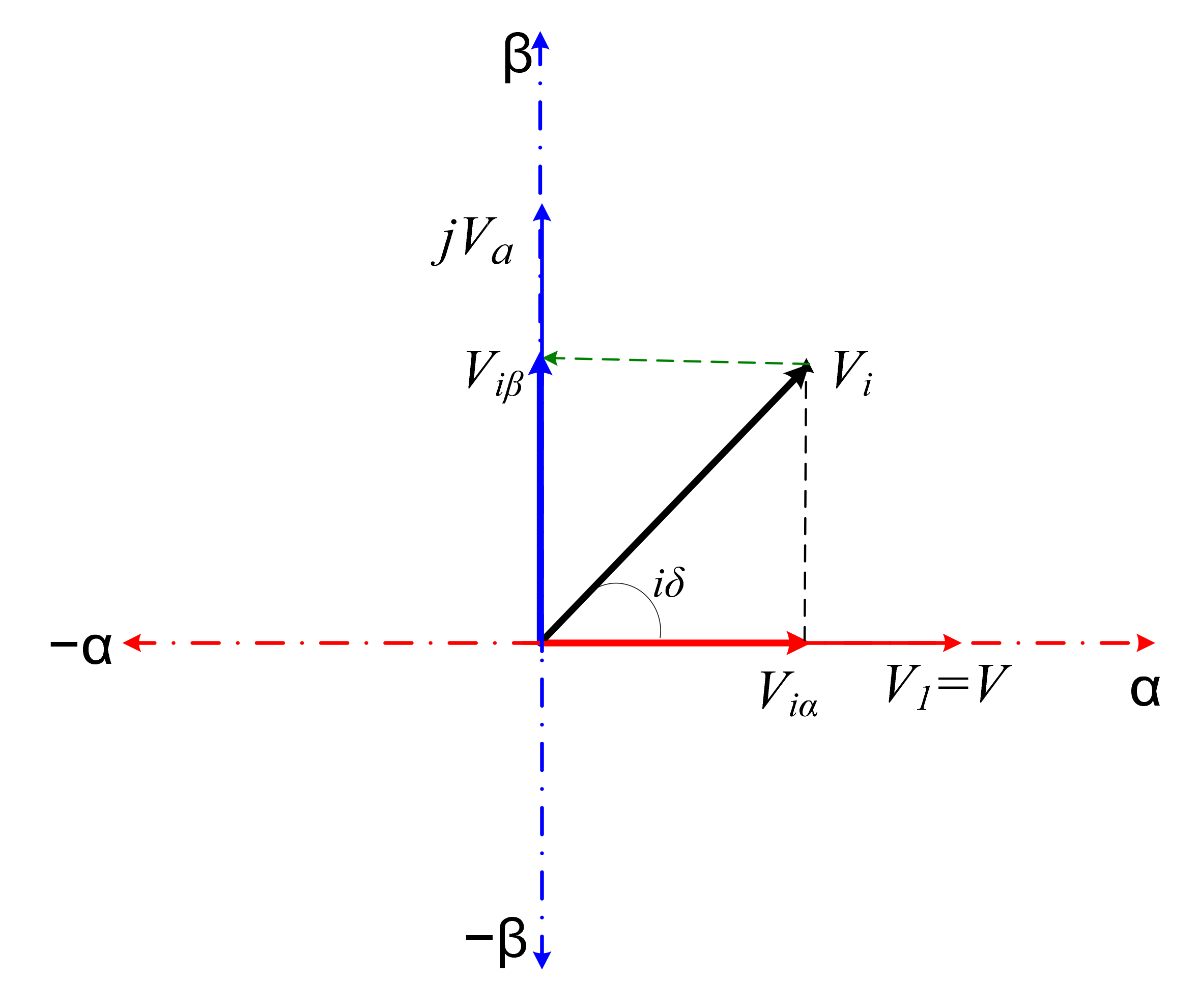
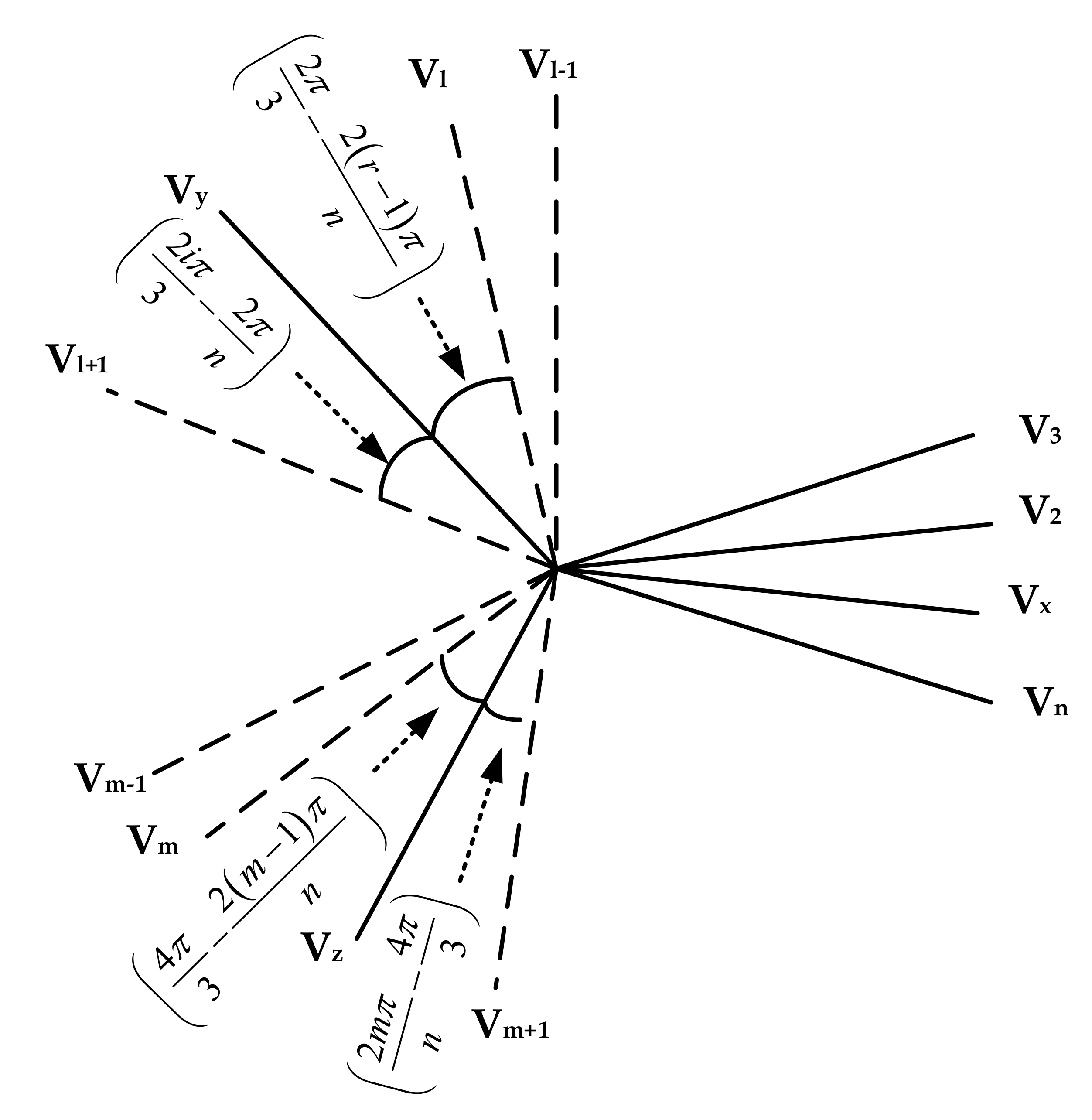
2.1.3. Three-Phase to n-Phase Transformation Using Phasor Algebra

This technique of transformation was found to be used in [5,6]. Although it is not as simple and straightforward as in [7,20,21], it is not too difficult to implement compared to the method discussed in Section 2. In this method, each phase of the multi-phase is constructed by the phasor addition of either of the two input phases, scaled down to a certain level. If compared with the input winding turn ratios, the scaling level can be computed by the generalized theory as shown below in Figure 4 [5].
It is obvious that the different phases of a three-phase to the n-phase transformer are constructed by phasor addition and or subtraction of part of three-phase x, y, z. Mathematically, the phase voltage of the transformer can be written as
V r = [ ± V x s i n θ + ± V y s i n ± V z s i n γ ]
where θ, ϕ, and γ are unknown to be derived. The above expression can also be written as below in a more generalized form.
V r = [ 1 a V x s i n θ + 1 b V y s i n + 1 c V z s i n γ ]
where r is the phase number, i.e., 1,2,3…n. The values of the parameter of Equation (18) can be written as below in (Equation (19)–(27)) [5].
V x = 0   w h e n   π 3 2 r 1 π n 2 π 3 or   4 π 3 2 r 1 π n 5 π 3
where n is the number of phases of the system:
V x = 0   w h e n   0 2 r 1 π n π 3 or   π 2 r 1 π n 4 π 3
V x = 0   w h e n   2 π 3 2 r 1 π n π or   5 π 3 2 r 1 π n 2 π
a = 1 ,   w h e n   2 π 3 2 r 1 π n 4 π 3   s m a l l   a r c 2 ,   w h e n   5 π 3 2 r 1 π n π 3 s m a l l   a r c
b = 1 ,   w h e n   4 π 3 2 r 1 π n 2 π   s m a l l   a r c 2 ,   w h e n   π 3 2 r 1 π n π s m a l l   a r c
c = 1 ,   w h e n   0 2 r 1 π n 2 π 3   s m a l l   a r c 2 ,   w h e n   π 2 r 1 π n 5 π 3 s m a l l   a r c
θ = π 3 2 r 1 π n ,   w h e n   0 2 r 1 π n π 3   2 r 1 π n 5 π 3 ,   w h e n   5 π 3 2 r 1 π n 2 π 2 r 1 π n 2 π 3 ,   w h e n   2 π 3 2 r 1 π n π 4 π 3 2 r 1 π n ,   w h e n   π 2 r 1 π n 4 π 3
= 2 π 3 2 r 1 π n ,   w h e n   π 3 2 r 1 π n 2 π 3   2 r 1 π n 2 π 3 ,   w h e n   2 π 3 2 r 1 π n π 2 r 1 π n 4 π 3 ,   w h e n   4 π 3 2 r 1 π n 5 π 3 2 π 2 r 1 π n ,   w h e n   5 π 3 2 r 1 π n 2 π  
γ = 2 r 1 π n ,   w h e n   0 2 r 1 π n π 3   2 π 3 2 r 1 π n ,   w h e n   π 3 2 r 1 π n 2 π 3 2 r 1 π n π ,   w h e n   π 2 r 1 π n 4 π 3 5 π 3 2 r 1 π n ,   w h e n   4 π 3 2 r 1 π n 5 π 3  
Equations (18)–(27) can be used to determine the number of turns ratios with respect to the three-phase input winding for a desired n-phase technique. A transformer is a bilateral network so the reverse transformation is also possible with the same transformer. It means three-phase can be produced from an n-Phase system. Figure 4 illustrates the phasor diagram of three-phase to n-phase transformation and vice versa.

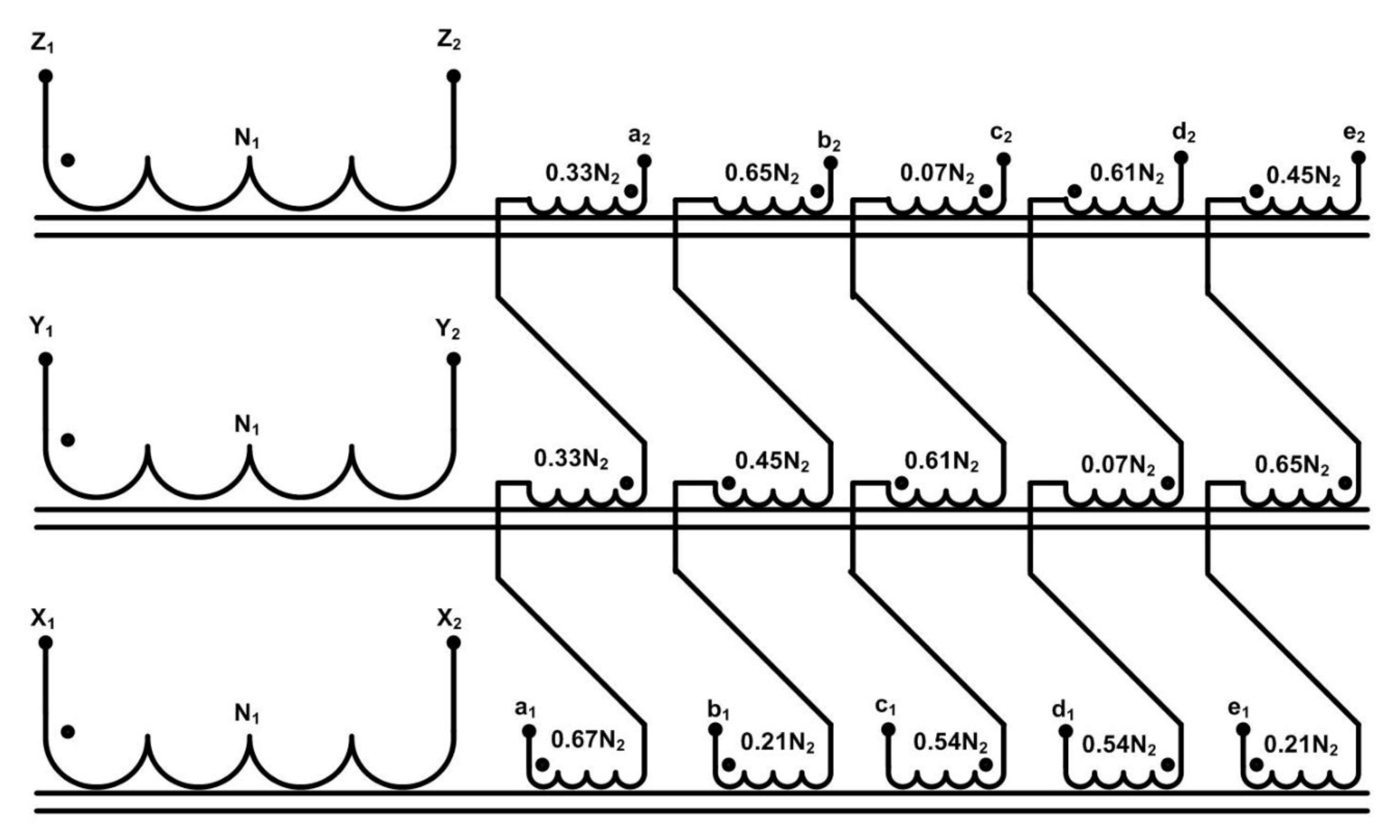
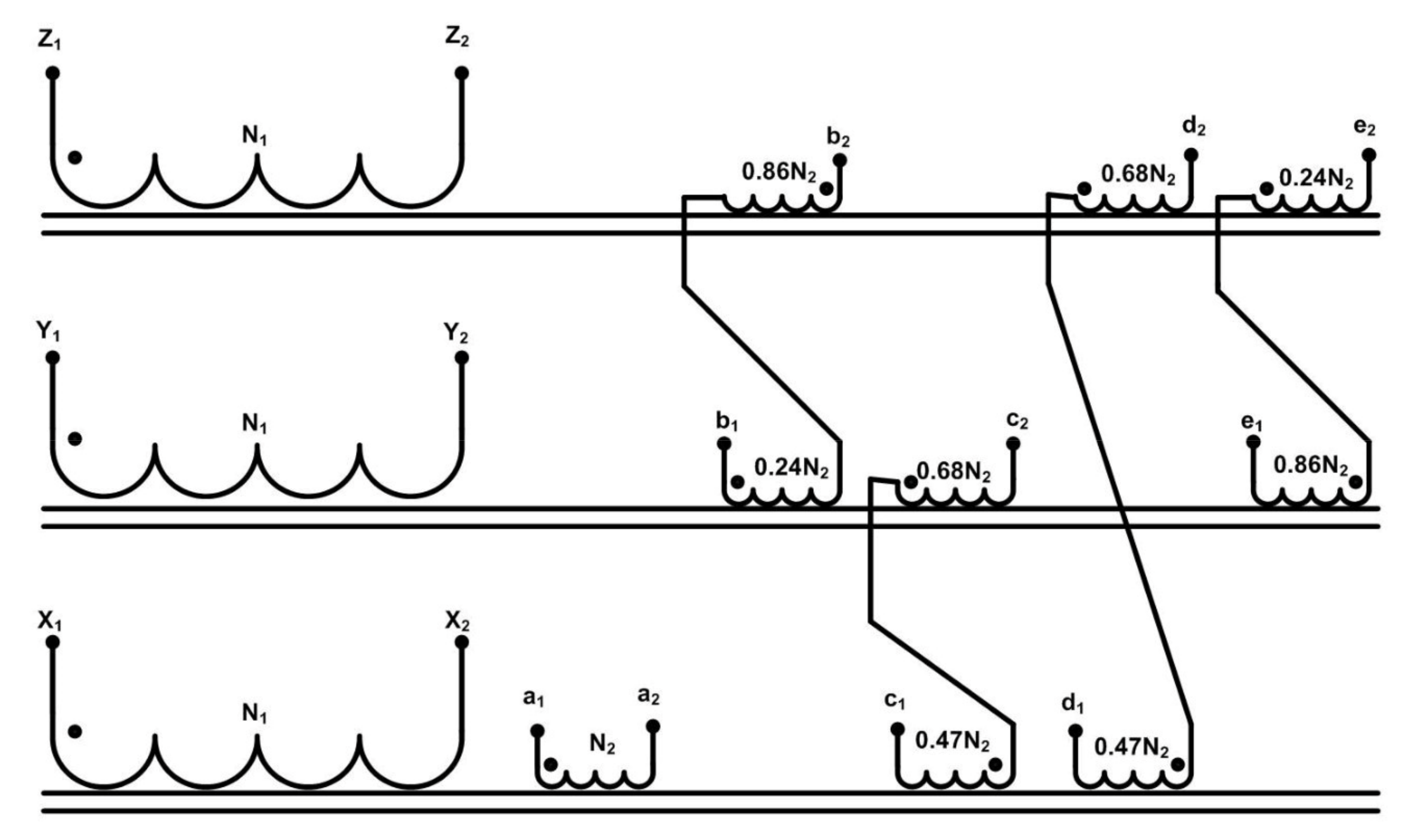
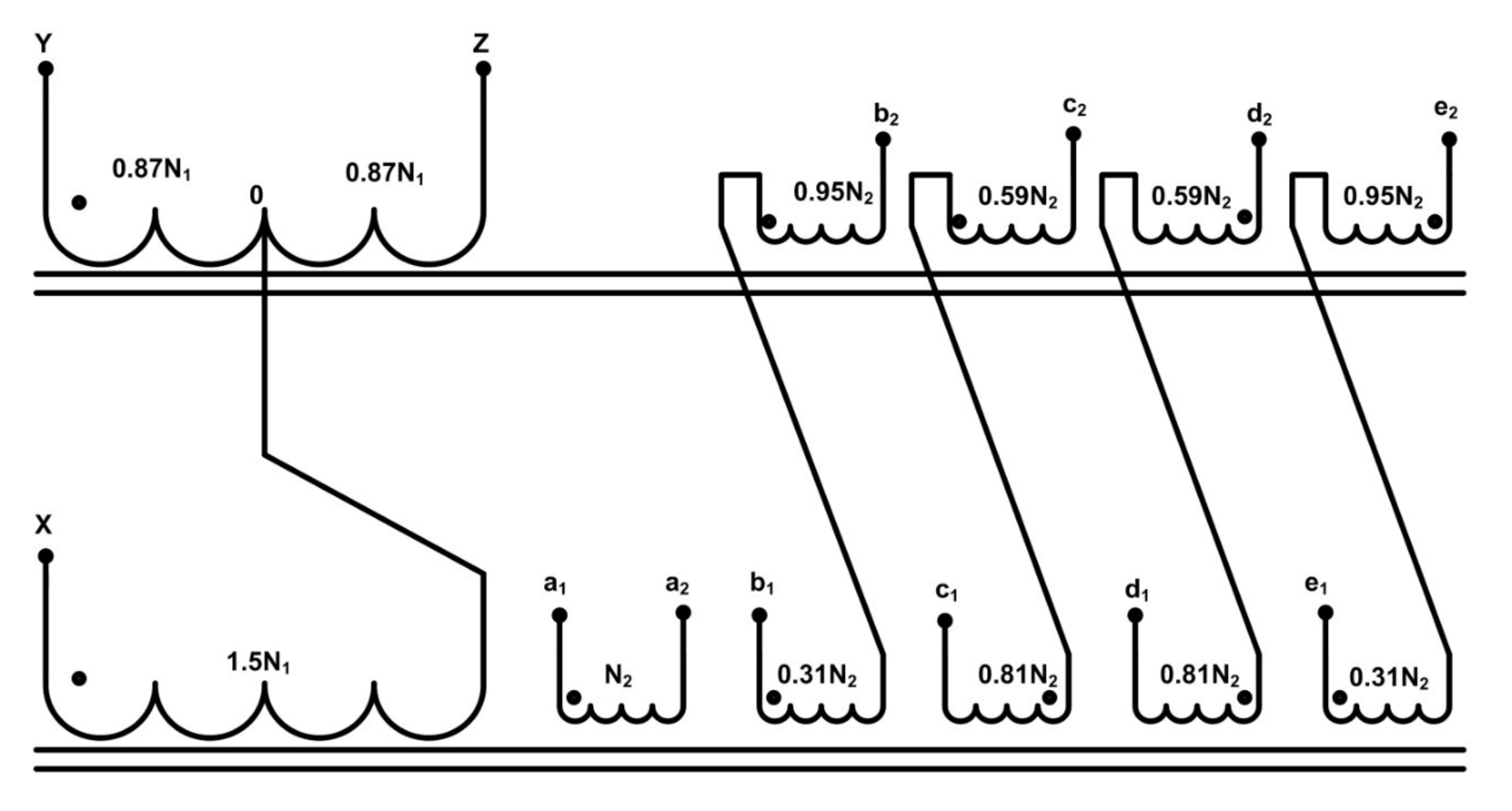
2.2. Three-Phase to Five-Phase Transformation Configurations

A three-phase to five-phase transformer consists of a core-type three-phase transformer with three separate limbs. Each limb comprising of a single primary coil and multiple secondary coils. These secondary coils are wound and connected such that the voltages add, and a 72-degree phase shift between each five-voltages is obtained in a predetermined method by joining the secondary coils comprising of an uneven number of turns. To design the transformer, three distinct configurations are considered. While considering the three-phase to five-phase transformation technique, three configurations are included to conduct the literature review. Additionally, a comparative analysis for the three-phase to five-phase transformation techniques, namely configuration 1, configuration 2, and configuration 3 [22]. Each transformation configuration is presented with the number of turn ratios and method for connecting different turns. The connection technique for configuration 1–3 with their turn ratio is depicted in Figure 5, Figure 6 and Figure 7. Figure 5 presents configuration 1 of a three-phase to five-phase transformer [22]., while Figure 6 and Figure 7 denote configuration 2 for a three-phase to five-phase transformation [6], and three-phase to the five-phase transformer is depicted in configuration 3 [7].

2.2.1. Configuration 1

In this scheme, the transformation occurs at a balanced three-phase supply input, i.e., the summation of all three input phase voltages equals zero [22]. In this scheme, it is possible to obtain a five-phase output by using only 15 secondary coils, thus decreasing the total number of turns and subsequently decreasing the size of the transformer compared with the other two proposed schemes (refer to Figure 5). Nonetheless, for configuration 1, there is no possibility of developing a pentagon connection at the secondary. Precisely, the secondary winding connection can only be carried out in the star topology, thus setting a limit on the utilization of the transformer. Moreover, the three-phase current in the presented connection technique denotes 5.6% of rated current, represented by a zero-sequence component. This requires the connection of a star point in the primary winding to permit neutral current flow.

2.2.2. Configuration 2

The transformation from three-phase input to five-phase output can be achieved by considering three different primary cores and several secondary windings [6]. Nevertheless, the two cores in the primary consist of three secondary windings resulting in a total of 14 secondary coils, as opposed to 15 in the first configuration.

2.2.3. Configuration 3

Another possible solution involves the transformer connection coils. According to the generalized theory presented in [1,7], the structure of a five-phase output can be developed by employing 2n − 1 or 9 secondary. The core volume is significantly minimized due to the application of only two cores to carry out the transformation. Subsequently, the increased utilization of turns results in a rise in resistance and further copper losses. The occurrence of high magnetizing reactance is also exhibited, which would result in significant iron losses and harm the effectiveness of the designed transformer.

2.2.4. Comparison of Design Parameters

All secondary coils had a similar cross-sectional area, which is not like the first scheme, where the cross-sectional area of one secondary coil is greater to deal with the flows of currents. In high-rating transformers, this could result in an irregular distribution of losses, leading to variable thermal loading; thus, a more complex cooling system would be required. The number of secondary winding turns required in configuration 1 is more than that needed in configuration 2 and 3. This would decrease the expense and enhance the proficiency of the transformer. A comparative study for the three schemes is presented in Table 2. It is observed from Table 2 that configuration 1 is utilized for a higher number of turns as compared to the other two configurations. Additionally, configuration 1 has bigger space requirements than the other two configurations.

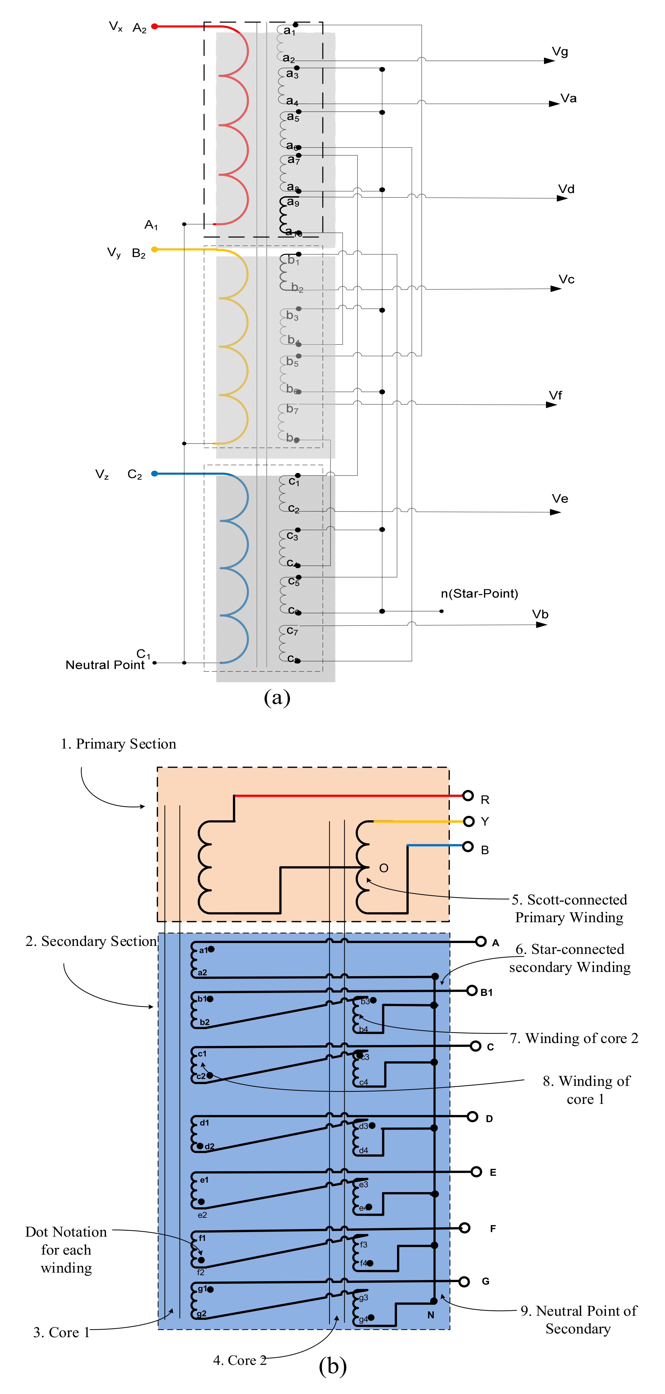
2.3. Three-Phase to Seven-Phase Transformation

The information and explanation regarding the multi-phase conversion technique from three-phase to seven-phase conversion are assessed and analyzed in [5,20]. The solution available in [5] is based on the method described in Section 2.3, while the solution presented in [20] is based on the method described in Section 2.3.

2.3.1. Configuration 1

In configuration 1, the primary side of the transformer is connected either in star or delta, while the secondary side of the transformer is connected distinctly, as presented in Figure 8b. The turn ratios and the windings connection are answers for developing a suitable number of phases. The number of turn ratios is assigned as per the information presented in Table 3. The phasor addition results in creating a phase difference of 51.43° between the phases. The stated transformer circuit has an input–output ratio of 1:1. To step up and step down, the voltage transformation ratio can be achieved by multiplying the number of turn ratios by a scaling factor.
This configuration utilizes either three single-phase transformers or a three-phase transformer. In a three-phase transformer-based scheme, the three separate iron cores will carry one primary and four secondary coils, except in one core where five secondary coils are wound. Six terminals of primaries are joined in a suitable way, which results in star or delta connections. Further, the secondary coils consisting of twenty-six terminals are connected in a predetermined style, resulting in the seven-phase winding with a star or heptagon connection.

2.3.2. Configuration 2

A new updated technique for phase transformation is presented in [20], which differs from the technique shown in [5], as this technique utilizes a primary winding Scott connection. The two-phase flux flow is carried out by employing two limbs, while the return flux path is circulated by utilizing the third limb. The primary outcome of configuration 2 is the generation of two-phase flux carried out by implementing the primary Scott connection. The ratio of the primary turn is 1 : 1 / 3 : 1 / 3 to produce the two-phase flux.
The seven-phase transformer with requisite phase differences is obtained by connecting the secondary winding, as shown in Figure 8a [5,20]. While connecting the windings appropriately, the turn ratios of the secondary winding should be as shown in Table 4:
V a V b V c V d V e V f V g = 1 0 cos ( δ ) sin ( δ ) cos ( 2 δ ) sin ( 2 δ ) cos ( 3 δ ) sin ( 3 δ ) cos ( 4 δ ) sin ( 4 δ ) cos ( 5 δ ) sin ( 5 δ ) cos ( 6 δ ) sin ( 6 δ ) V α V β
Here, aα and aβ represent secondary winding turn ratios with regard to primary windings RO and YB, respectively. Specifically, the turn ratios can be tabulated from Equation (12), as presented in Table 4. A positive sign represents the summation of phase voltages, while the negative sign denotes the subtraction of phase voltage. A phase difference of 51.42° is obtained between the output phase voltages by employing suitable turn ratios. The governing phasor equations are illustrated in [20].
Multi-phase power systems possess two or more line voltage contrasts to a three-phase system where only one line voltage appears. Likewise, a five-phase system has one line voltage, a second line voltage (adjacent line voltage), and a third line voltage (nonadjacent line voltage), as defined in [23]. Similarly, a seven-phase system’s line voltages are defined as follows [24]:
(a)
Phase Voltage: Phase voltage with regards to neutral or star point O (e.g., Va, Vb, Vc, Vd, Ve, Vf, and Vg);
(b)
Adjacent Line Voltage: The voltage difference of two phases having a phase difference of 51.42° (e.g., Vab1, Vb1c, Vcd, Vde, Vef, Vfg, and Vga);
(c)
Nonadjacent1 Line Voltage: The voltage difference of two phases having a phase difference of 2 × 51.42° (e.g., Vac, Vb1d, Vce, Vdf, Veg, Vfa, and Vgb);
(d)
Nonadjacent2 Line Voltage: The voltage difference of two phases having a phase difference of 3 × 51.42° (e.g., Vad, Vb1e, Vcf, Vdg, Vea, Vfb1, and Vgc).

2.4. Other High Phase Order Systems

2.4.1. Three-Phase to Eleven-Phase System

A three-phase to the eleven-phase transformer was researched in [21,25,26], but [21] is worth reporting here. This transformation is based on the algorithm discussed in Section 2.1.2. Genetic algorithm-based optimization is used to design the winding turn number and the turn ratio. It is made out of four stages. The first stage relates to selecting the starting population that represents the winding turn number Ni1, Ni2, and Ni3. The second stage refers to the selection of the best individual by utilizing the technique of tournament selection [27]. The third stage is the crossover of the best individual, while the fourth stage presents the mutation to generate a new population.
The determination of the best individual was finished by considering the criteria of the reduced root mean square (RMS) error. This criterion was utilized to reduce the RMS error between the ideal eleven-phase voltage and the obtained eleven-phase voltages that were calculated by utilizing the algorithm discussed in Section 2.1.3. A subsequent condition was applied to lessen the number of windings utilized, which was meant to increase the simplicity and reduce the complexity. The introduced approach benefited from evading the analytical calculation while searching for the appropriate number of turns and proper configuration or connection of windings.
Referring to Equation (17), the smallest component from every column of the matrix Mx is not considered and marked as zero and the evaluation is performed again to fit different components so that RMS error is minimized. Further, in the case of star-connected winding on the secondary of the transformer, if two or more elements of a column were equal, then they shared only one winding to create the output voltage. On the way toward diminishing the matrix elements, some elements were set to zero, and the matrix was reoptimized to fit the best values. A new matrix is received, and it can be realized that a high RMS error in certain phases such as two, three, eight, ten, and eleven can be obtained [21]. This indicates that the eliminated values of the matrix were not right, and they needed to be changed. Finally, matrix Mx was optimized, and the output turned out to be a balanced eleven-phase system, as shown in Figure 9 and Figure 10 [5,6,7,21,25,26], along with the five-, seven- and thirteen-phase systems.

2.4.2. Three-Phase to Thirteen-Phase Transformer

A unique thirteen-phase transformer that converted the three-phase supply to a balanced thirteen-phase output was designed and simulated in MATLAB [28]. The underlying design theory was the same as [5,6,22] and the one discussed in Section 2.1.3. The input terminal and output terminal could be configured with the following connections:
  • A star-connected input and star-connected output;
  • A star-connected input and tridecagon-connected output;
  • A delta-connected input and star-connected output;
  • A delta-connected input and tridecagon-connected output.
Vm, …… Vz denotes the thirteen-phase voltage, while Vi, Vj, and Vk denote the three-phase input voltages. The turn ratios for a balanced thirteen-phase output for a 1:1 transformer are shown in the matrix (Equation (29)). The matrix has to be multiplied by a scaling factor for a step-up or step-down transformer. The thirteen-phase output is shown in Figure 10e. The configuration of various transformation techniques for multi-phase transformation is presented in Table 5.
V m V n V p V q V r V s V t V u V v V w V x V y V z = 1 sin π 3 × sin π 3 0 0 sin 7 π 39 0 sin 2 π 13 sin π 39 0 sin 4 π 13 0 sin 5 π 39 sin 8 π 39 0 sin 6 π 39 sin 11 π 39 sin 4 π 39 sin 3 π 39 0 sin 10 π 39 sin π 13 0 sin 10 π 39 0 sin π 13 sin 4 π 39 0 sin 3 π 13 0 sin 2 π 39 sin 11 π 13 0 sin 8 π 39 sin 5 π 39 sin π 39 sin 4 π 13 0 sin 7 π 39 sin 2 π 13 0 V i V j V k

3. Applications of a Multi-Phase Transformer

3.1. Electric Drives

A multi-phase system has numerous applications in generators [29], high-performance drives [30,31,32], transmissions [33,34,35,36,37], power quality improvement [38], wind energy conversion systems [39], and power supplies [40]. The requirement of accurate motor parameters is essential for multi-phase motor drives such as direct torque control (DTC) or field-oriented control (FOC) to obtain high performance and efficiency.
For the applications of variable speed control of multi-phase electric motors, the appropriate number of parameters is assigned by the controller such as stator and rotor resistance, leakage and magnetizing reactance, iron loss component resistance, stray reactance, and inertia [39]. The motor undergoes various tests such as the no-load, load, and blocked rotor tests to obtain the needed parameters. Such tests require a pure sine wave supply. Usually, the pure sine wave is not generated by the power electronic converters [41,42,43]. A multi-phase transformer can be used effectively to find the precise machine parameters that are required in highly efficient electrical drives for multi-phase motors, such as field-oriented control (FOC) or direct torque control (DTC). Henceforth, the possible solution is the utilization of a transformer that transforms the readily available three-phase grid supply to the desired n-phase (where n > 3), which, in a later stage, is used as a pure sine wave multi-phase source. Moreover, higher cost-effectiveness and reliability with the desired multi-phase output at fixed speed operations are achieved by utilizing an improved passive transformer design. The power electronics converter is most suitable for variable frequency drives. At the same time, the transformer is used where pure sine wave multi-phase application is required, or there are fixed frequency application requirements. The power electronics converter might have a high THD, while the multi-phase transformer may show an increased imbalance in the output voltage. As such, both solutions have their advantages and disadvantages, and the superiority of one over the other is purely application-based.

3.2. Transmission of Bulk Power

The employment of six-phase and twelve-phase power systems is carried out for the economical transmission of bulk power. The six-phase and twelve-phase power systems are an effective solution for the transmission lines traveling through agricultural lands, mountains, forests, and so forth [33,34,35,36,37]. The necessity of three to six-phase transformation is needed in AC–DC converters circuits. The number of phases from 6 to 40 are introduced in the literature for AC–DC converter supplies. The higher the number of phases at the converter’s input, the lower the ripples in the DC outputs that improve the current shape at the source side are.
Multi-phase systems can be utilized for various applications, such as offshore energy harvesting, electrical vehicles, electric ship propulsion, and airplanes. The previous proposed research depicted the superior quality of multi-phase machines for acquiring better and more reliable performance.
One of the most crucial research fields of multi-phase transmission systems is developing an improved protection system for multi-phase power such as the development of a six-phase circuit breaker and its optimal placement for the most suitable protection region).

3.3. Wind Energy Conversion System

Multiple researchers suggested the application of multi-phase generators and a seven-phase to the three-phase transformer in wind energy conversion systems (WECSs) [37]. Recent advances in the field of multi-phase static transformation include design, modeling, and protection scheme development [44,45,46,47,48]. Multiple researchers suggested the application of multi-phase generators and a seven-phase to the three-phase transformer in wind energy conversion systems (WECSs) [39]. Recent advances in the field of multi-phase static transformation include design, modeling, and protection scheme development [44,45,46,47,48]. In [39], the work was based on the application of a seven-phase induction generator, a rectifier, and an inverter. The schematic block diagram for the potential application of a multi-phase (seven-phase) induction motor and a three to seven-phase transformer-based DFIG concept is presented in Figure 11. This arrangement shall be more efficient and economical compared with that presented in [39].
Very recently, a comprehensive state-of-the-art overview on the monitoring, fault diagnosis, and prognosis of wind turbine systems was addressed in [49], which promoted the research and development of reliability and safety for wind turbine systems. The proposed technique also provided the monitoring and diagnosis operation for power transformers and power systems. The wind energy industry has strong demand to increase system reliability and fault detection due to the 10–35% total life cost in maintenance. Signal-based, model-based, knowledge-based, and hybrid approaches are the well-known methods that were found in the literature for the diagnosis of faults in WECSs. Model-based fault diagnosis and monitoring algorithms have excellent real-time efficiency due to their onboard implementation and off-line design. Signal-based fault diagnosis and monitoring approaches utilize the measured signals of sensors that are more convenient for implementation. Knowledge-based approaches use historical data for training and searching.
The prognosis methodology requires deep research and development compared with fault diagnosis and condition monitoring due to the complexity of wind turbine systems. The prognosis and resilient control methodologies are beneficial in the condition monitoring, and fault diagnosis approaches [49].

3.4. HVDC Transmission System

Transformer rectifier units (TRUs) are used more in electric aircraft, HVDC transmission systems, wind energy conversion systems, and -pulse, 6-pulse, 12-pulse, 24-pulse, and 48-pulse TRUs based on one or more three-phase transformer connections were found in the literature. A higher number of pulses reduces the ripple voltage while increasing the ripple frequency. This leads to reduced filter requirements. The application of a multi-phase transformer in place of a three-phase transformer will undoubtedly improve the output DC voltage, reduce ripple, and lower the size of the filters. A comparison of three-phase and seven-phase TRU pulses in a single cycle is shown in Table 6.
It was suggested in [21] that a single winding be used if duplication occurred to reduce complexity. If a single winding is used for the combination of two different phases, the winding must carry additional current so that a particular winding can be designed to carry the extra current. It is better to use two windings instead of one for uniform current distribution among each winding.
The multi-phase transmission system was more economical and has a lower tower height and bulk power transmission compared with its three-phase counterpart. The most crucial part of the multi-phase power system is the protection system. The protection system and circuit breakers are essential for developing a multi-phase power system. Work in this area was not available in the literature. One of the applications of a multi-phase transformer for power quality improvement is depicted in Figure 12 [38].

4. Issues and Challenges of Multi-Phase Transformer

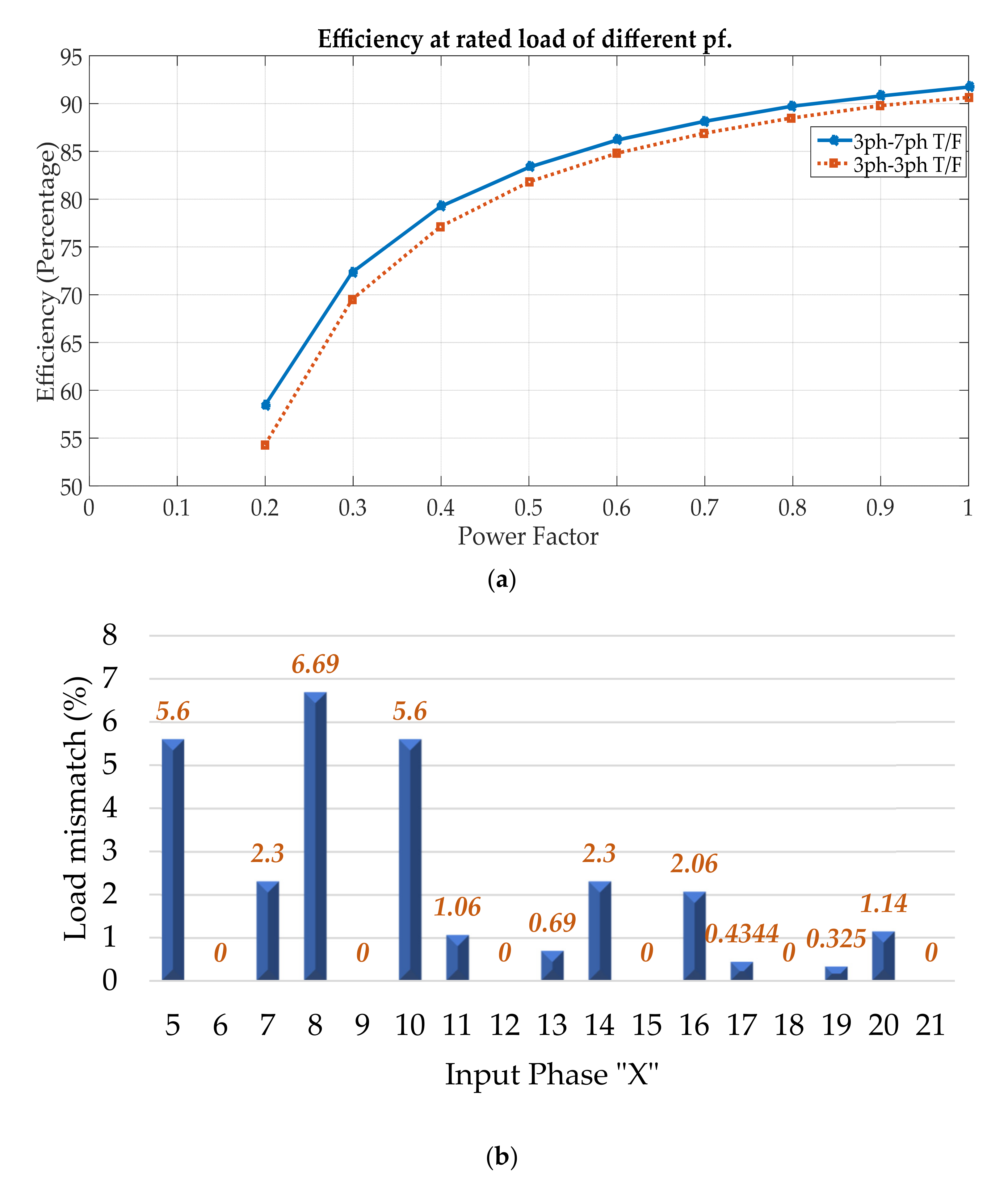
4.1. Impedance Mismatching

One of the key concerns for implementing the multi-phase transformer technique is impedance mismatching. Impedance mismatching is introduced due to the different number of turns in the secondary winding of a multi-phase transformer. It is evident that at a lower current value, the phenomena of impedance mismatching is not noticeable. However, at a higher magnitude of current, a different value of output voltage from each secondary phase is obtained due to different phases impedance leading to the unbalanced output voltage. In the study of load mismatch, it was found that the systems which were multiples of 3 (e.g., 6, 9, and 12) had zero mismatches, whereas the five-phase and ten-phase systems had a mismatch of 5.6%, and the seven-phase and fourteen-phase systems had a mismatch of 2.3% [5]. The four-phase system delivered the highest mismatch of 50% [5]. It is observed that mismatch is decreased when the phase system number increases, particularly with prime-numbered systems, as the acquired mismatch was 0.325% for a nineteen-phase system [5,6]. Apart from the limitations of impedance mismatching in multi-phase transformer applications, the issue of mismatching in load sharing is also considered, which is associated with high-order phase operation. Therefore, these issues are explored in this review article. As far as efficiency is concerned, a three-phase to seven-phase transformer was found to be more efficient compared to a three-phase to three-phase transformer of a similar rating [5]. Figure 13a depicts the efficiency comparison at different pf values, while Figure 13b shows the impedance mismatch of an n-phase system [5].

4.2. Voltage Unbalance

Standardization and definition of sequence networks for higher-order phase systems are required. The phase voltage unbalance factor (PVUF), line voltage unbalance rate (LVUR), voltage unbalance factor (VUF), and complex voltage unbalance factor (CVUF) are the factors that may be used to study unbalancing in multi-phase power [50]. The PVUF in a seven-phase system was reported in [50].
The voltage unbalance in the output voltage of the transformer appears due to impedance mismatching. Any unbalanced n-phase system can be converted into a set of n − 1 balanced n-phase systems with a zero sequence, according to the well-known work by Fortescue work. For example, an unbalanced three-phase voltage can be broken into sequence components such as positive sequence, components, negative sequence components and zero sequence components. Similarly, a five-phase unbalanced voltage can be converted into similar five sequence components and a seven-phase voltage into seven. The references are found in the literature for the definitions of five-phase sequence networks [23] and seven-phase systems [24]. This nomenclature for these sequence networks shown in Table 7 is author-defined only.

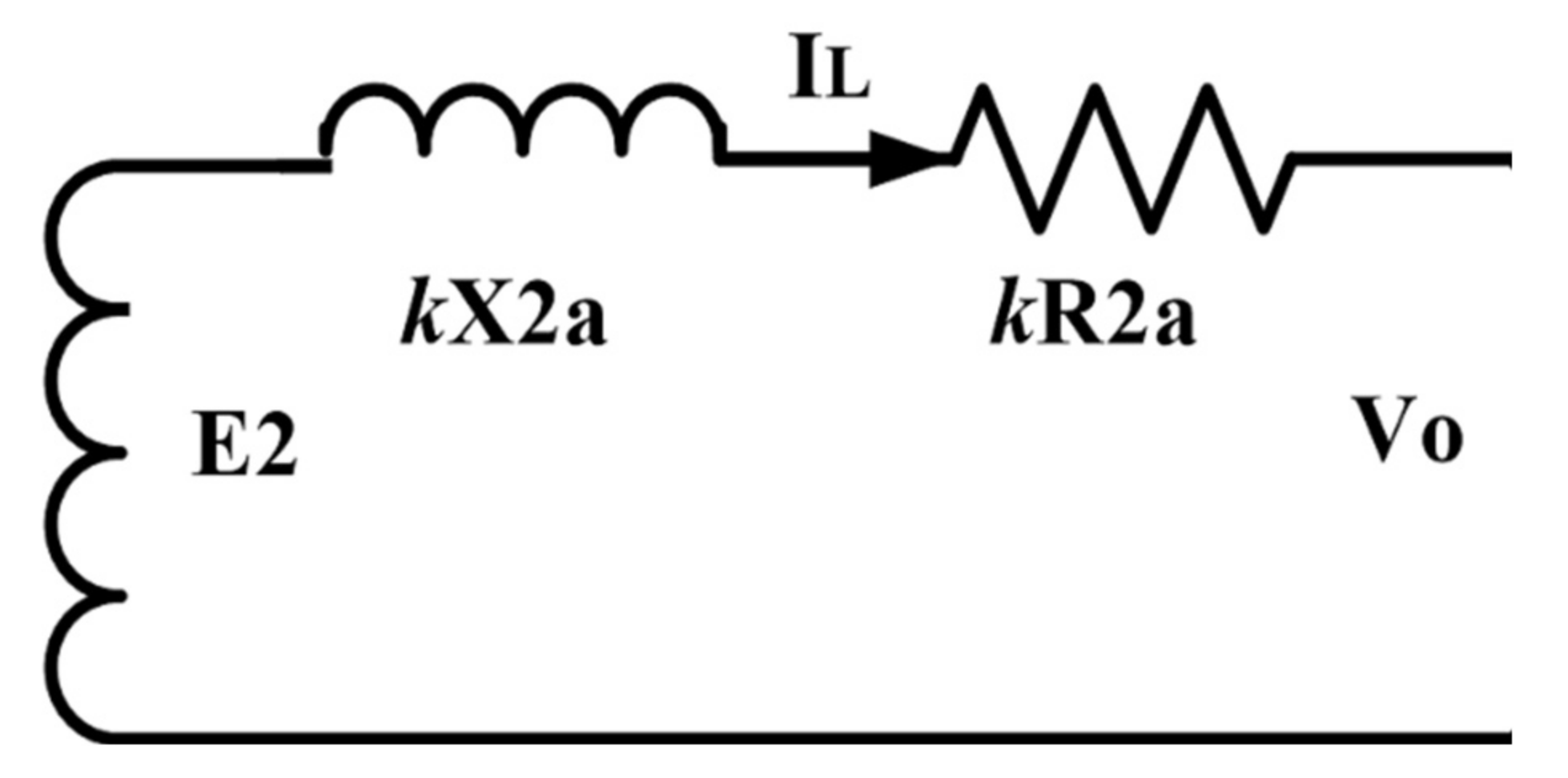
4.3. Per-Phase Equivalent Circuit Modeling

The application of a per-phase equivalent circuit is considered an important tool to study multi-phase transformer techniques. Although the application of three-phase to five- or seven-phase transformation techniques are mentioned [5,6,20], effective solutions to address the mismatching issue with a secondary winding, the per-phase equivalent circuit modeling, are still in a primitive stage. The research investigation covers the development of a per-phase equivalent circuit similar to a three-phase transformer study. Since the primary side is already three-phase, thus the objective is to model for the secondary side only. In Figure 14, it can be observed that all the secondary side of a multi-phase (seven-phase in this case) consists of different series resistances and reactances. In Figure 15, it is shown that after the application of the optimization technique, a single equivalent circuit can be used for each phase. The artificial intelligence-based per-phase equivalent circuit modeling can addressed the mismatching issues [51]. In [52], Secondary side of a seven-phase transformer is optimized by utilizing genetic algorithm (GA) and particle swarm optimization (PSO) for the development of per-phase equivalent circuit. Both the optimization schemes can be utilized for modeling the multi-phase transformer circuits that pose unbalancing as a challenge [51].

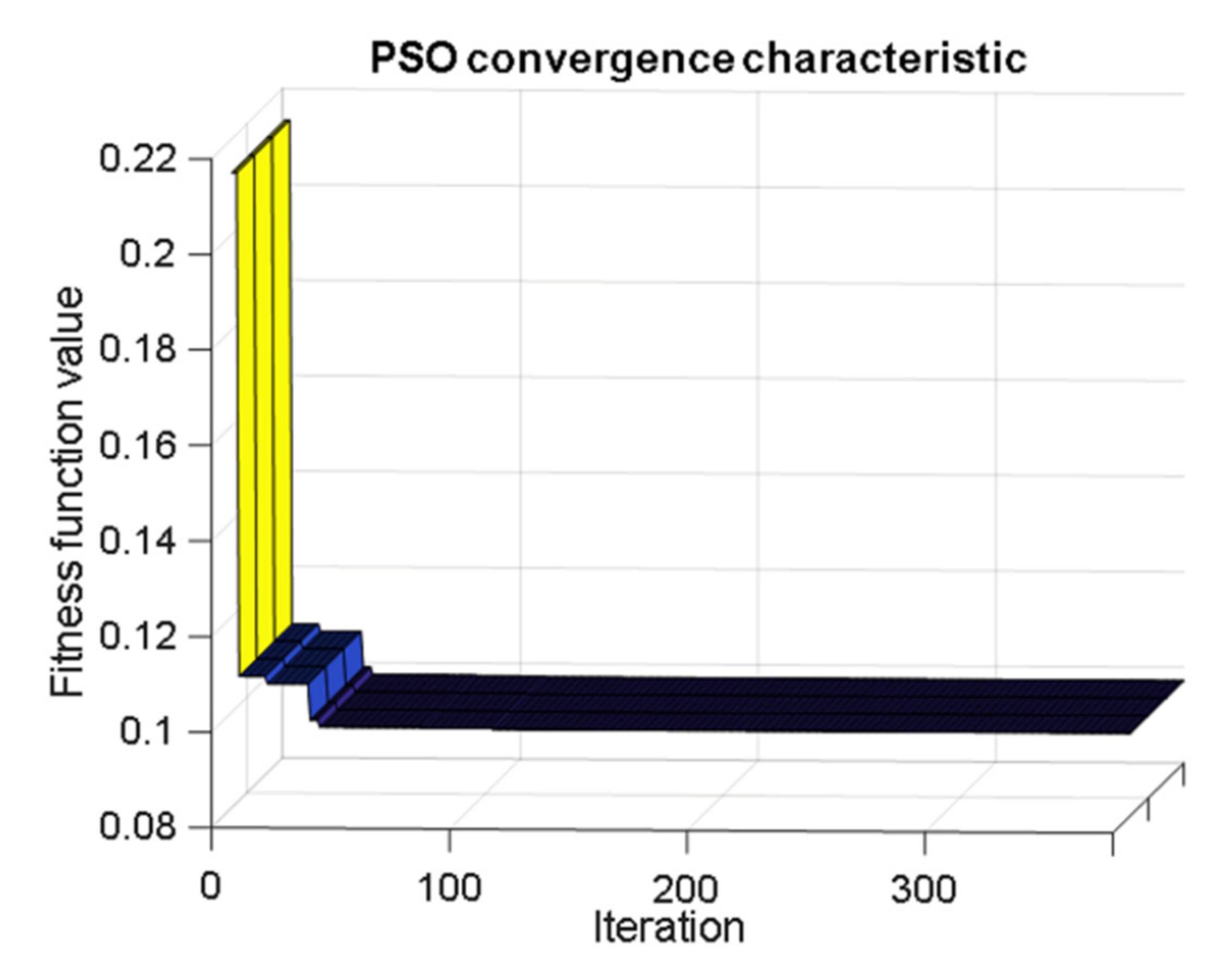
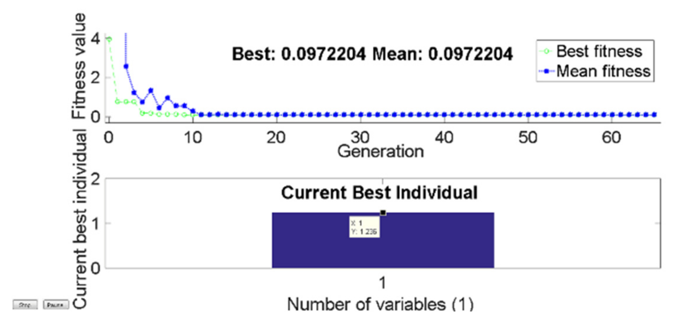
4.3.1. Formulation of Objective Function and Analytical Modeling

Refer to Figure 14, if resistances and self-inductance of the reference phase (Phase a) are assumed to be R2a and X2a then resistances and inductances of the rest of the phases can be expressed in terms of the reference phase as below.
R b = 1.4052 R a ,   X b = 1.4052 X a R c = 1.1974 R a ,   X c = 1.1974 X a R d = 1.3347 R a ,   X d = 1.3347 X a R e = 1.3347 R a ,   X e = 1.3347 X a R f = 1.1974 R a ,   X f = 1.1974 X a R g = 1.4052 R a ,   X g = 1.4052 X a
Output voltages of all seven phases under steady-state conditions can be deduced from the circuit diagram shown in Figure 14 as below.
V o a = E 2 I L R 2 a + j X 2 a V o b = E 2 I L R 2 b + j X 2 b V o c = E 2 I L R 2 c + j X 2 c V o d = E 2 I L R 2 d + j X 2 d V o e = E 2 I L R 2 e + j X 2 e V o f = E 2 I L R 2 f + j X 2 f V o g = E 2 I L R 2 g + j X 2 g
The output voltage of the per-phase equivalent secondary circuit is
V o = E 2 I L k R 2 a + j k X 2 a
Let us formulate the error voltage (difference of secondary voltages) as the objective function,
f 1 ( k ) = V o V o a = E 2 I L k R 2 a + j k X 2 a E 2 I L R 2 a + j X 2 a = I L ( ( k 1 ) R 2 a + j ( k 1 ) X 2 a )
Similarly
f 2 ( k ) = I L ( ( k 1.4052 ) R 2 a + j ( k 1.4052 ) X 2 a ) ) f 3 ( k ) = I L ( ( k 1.1974 ) R 2 a + j ( k 1.1974 ) X 2 a ) ) f 4 ( k ) = I L ( ( k 1.3428 ) R 2 a + j ( k 1.1.328 ) X 2 a ) ) f 5 ( k ) = I L ( ( k 1.3428 ) R 2 a + j ( k 1.1.328 ) X 2 a ) ) f 6 ( k ) = I L ( ( k 1.1974 ) R 2 a + j ( k 1.1974 ) X 2 a ) ) f 7 ( k ) = I L ( ( k 1.4052 ) R 2 a + j ( k 1.4052 ) X 2 a ) )
It is clear from Equation (33) that f 1 ( k ) , f 2 ( k ) , f 3 ( k ) ,   and   f 4 ( k ) are the only objective functions to be optimized for this multi-objective optimization problem. This problem is solved by making a single objective function and then using the PSO algorithm to find the best value of the variable, k. The aim of the optimization problem is to achieve the best value of k for which the functions (given in Equation (34)) have the least value. For this, a common objective function (or fitness function) is defined and is written as:
O F ( k ) = 1 R 2 a 2 + X 2 a 2 I L 2 [ f 1 ( k ) 2 + f 2 ( k ) 2 + f 3 ( k ) 2 + f 4 ( k ) 2 ]
The terms for functions f5(k), f6(k) and f7(k) will have the same effect as that due to functions f4(k), f3(k) and f1(k), respectively, so these terms have not been used in the objective function. This optimization problem is a minimization problem such that OF has the minimum value for a particular value of k.
The application of PSO for finding the best value of k using the defined fitness function OF was represented in the flowchart in Figure 16. Similarly, GA was applied to find the best value of k using the defined OF.

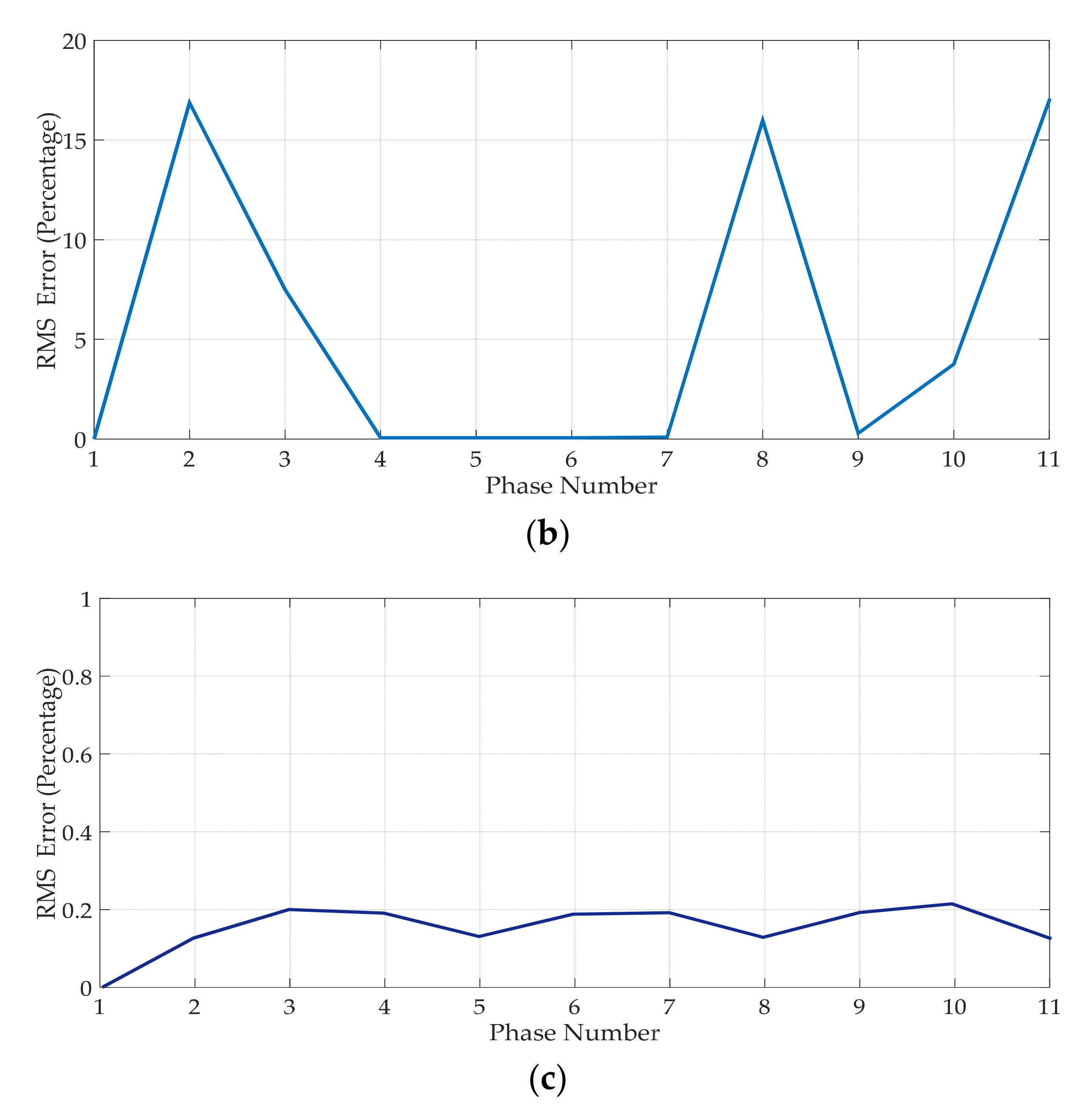
4.3.2. Simulation Results

The circuit configurations and results of the work are shown in Figure 8b, Figure 17, Figure 18 and Figure 19 [51] and Table 8, respectively. Figure 17 shows the 3D representation of the results obtained for the PSO convergence characteristic using MATLAB as the variation of the value of an objective function with respect to the value of k. It can be observed that the value of the fitness function converges to its minimum value before the 50th iteration. It can be seen that the global optimum point is tracked, and the curve gets converged with a few iterations. The convergence characteristic outcomes for GA are shown in Figure 18. It is observed that the convergence to the optimal value using GA is obtained at a faster rate and the final value is achieved with only 10 iterations. Thus, GA has a faster convergence rate compared to PSO. However, the optimized value obtained by PSO is more precise compared to GA results which are shown in Table 8. The value of k is found to be 1.236.
The per-phase equivalent circuit of the secondary side of the transformer is shown in Figure 19 and can be employed for different studies such as voltage, regulation, efficiency calculation and single-lone diagram, etc. The value of per phase reactance and resistance can be obtained using the optimum value attained by the PSO method (discussed in detail in Section 4.3.1).

4.4. Fault Analysis of a Multi-Phase Transformer

Several techniques are used for faults, condition assessment, and monitoring in a three-phase transformer [53,54,55].
These methods hold for a three-phase to the multi-phase transformer. As far as winding deformations caused by mechanical forces are concerned, originating from EMFs induced in the coil, most of the methods failed. Frequency response analysis (FRA) was best suited for condition assessment and monitoring the deformations in a winding [56].
A transformer has winding resistance, winding, inductance, and capacitance due to insulation layers between the coils, windings, winding and core, core and tank, and tank and winding, among others. Therefore, a transformer can be considered a complex RLC network [57]. Any physical damage to a transformer will result in a disturbance to the original RLC network. FRA is based on the concept that physical damage will alter the RLC network and the network transfer function’s various frequencies [58]. A multi-phase transformer or a multiphase solid-state transformer and its fault studies may be the key research area for future study [59,60]. Table 9 summarizes the testing methods and their application areas.
In [54], a new application of DGA for faults in on-load tap changers (OLTCs) was reported apart from the other six types of fault detection by DGA.
In addition to the discussion outlined above, this review identifies several key problems, issues, and challenges related to power conversion using various phase transformation techniques which are highlighted below:
  • Fault Analysis of Multi-phase System: The fault analysis is an essential tool for evaluating various faults occurring in a specified electrical system. The appropriate information and data are needed to choose various equipment of specified ratings. The existing research works on fault analysis for a three-phase system is mature and abundant in literature but Fault analysis for a multi-phase system is absent. Therefore, an in-depth investigation is needed to develop a fault analysis mechanism of a multi-phase system.
  • Per-phase equivalent circuit: An important design consideration to analyze various multi-phase transformation techniques is implementing the per-phase equivalent technique. A per-phase equivalent circuit is an Unequal number of turns in each winding of a multi-phase transformer that leads to unequal series impedance. Therefore, developing a per-phase equivalent circuit for a multi-phase transformer is a challenging task and maybe future research direction.
  • Fixed Frequency operation: Usually, the converter circuits operate at a fixed frequency; nonetheless, the phase displacement controls the output voltage at the latter conversion stages. In the case of a transformer, the operation is conducted at a fixed frequency; nonetheless, it is not suitable for a variable frequency drive. In association with this multi-phase VSI has superiority over multi-phase transformer.
  • Lack of multi-phase Circuit breaker and Relays: The circuit breaker and relays are considered important equipment for control and protection in electrical power systems. However, the application of multi-phase circuit breakers and relay has not been explored significantly. Therefore, the development of circuit breakers and relays operating at multi-phase power might be breakthrough research.

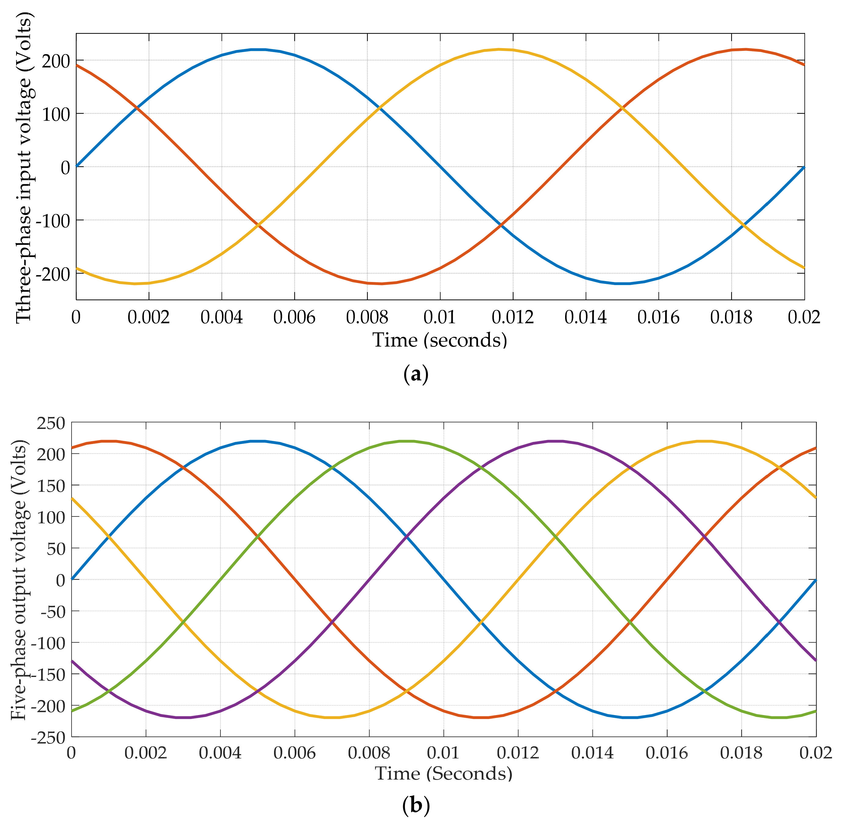
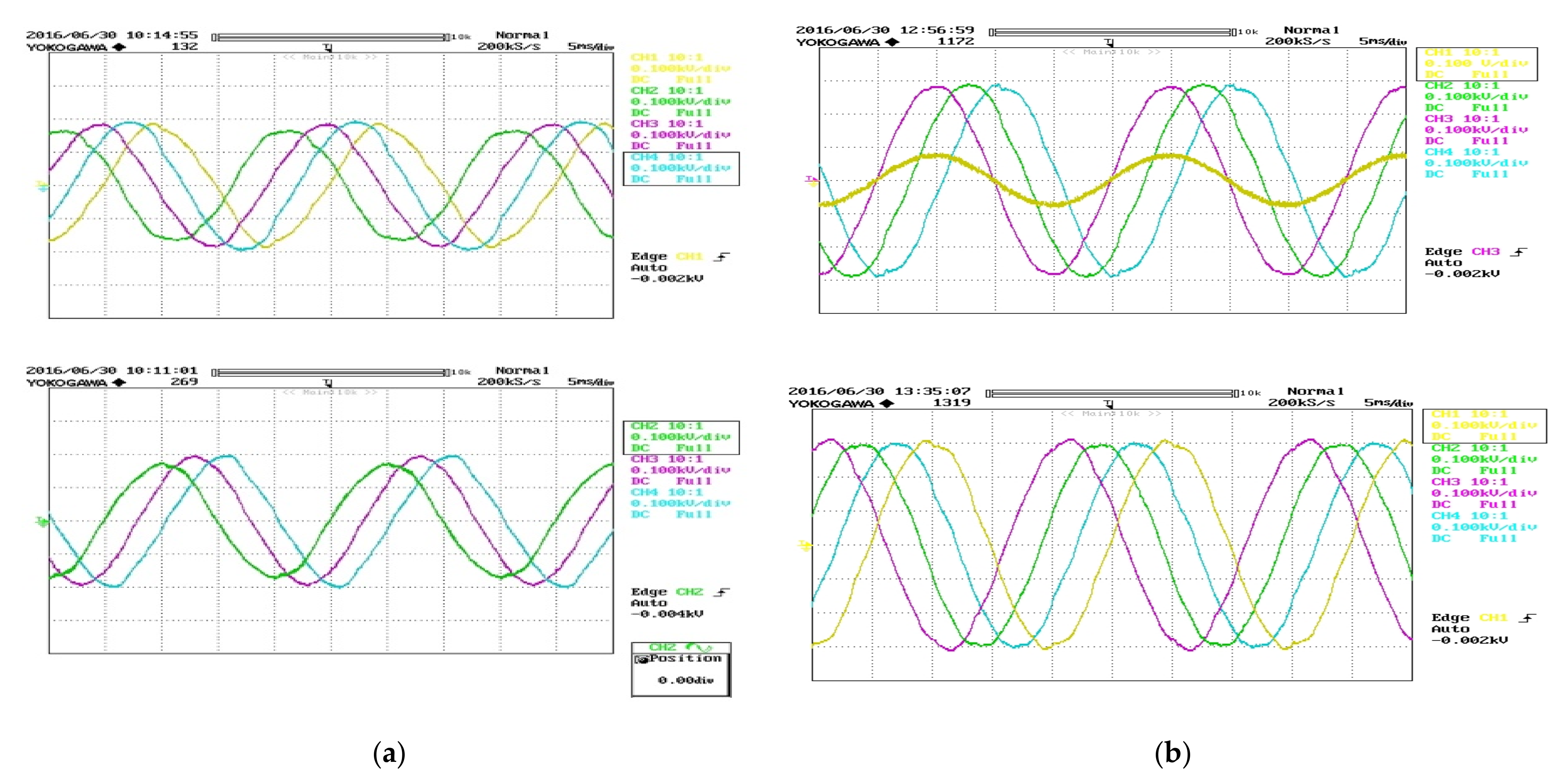
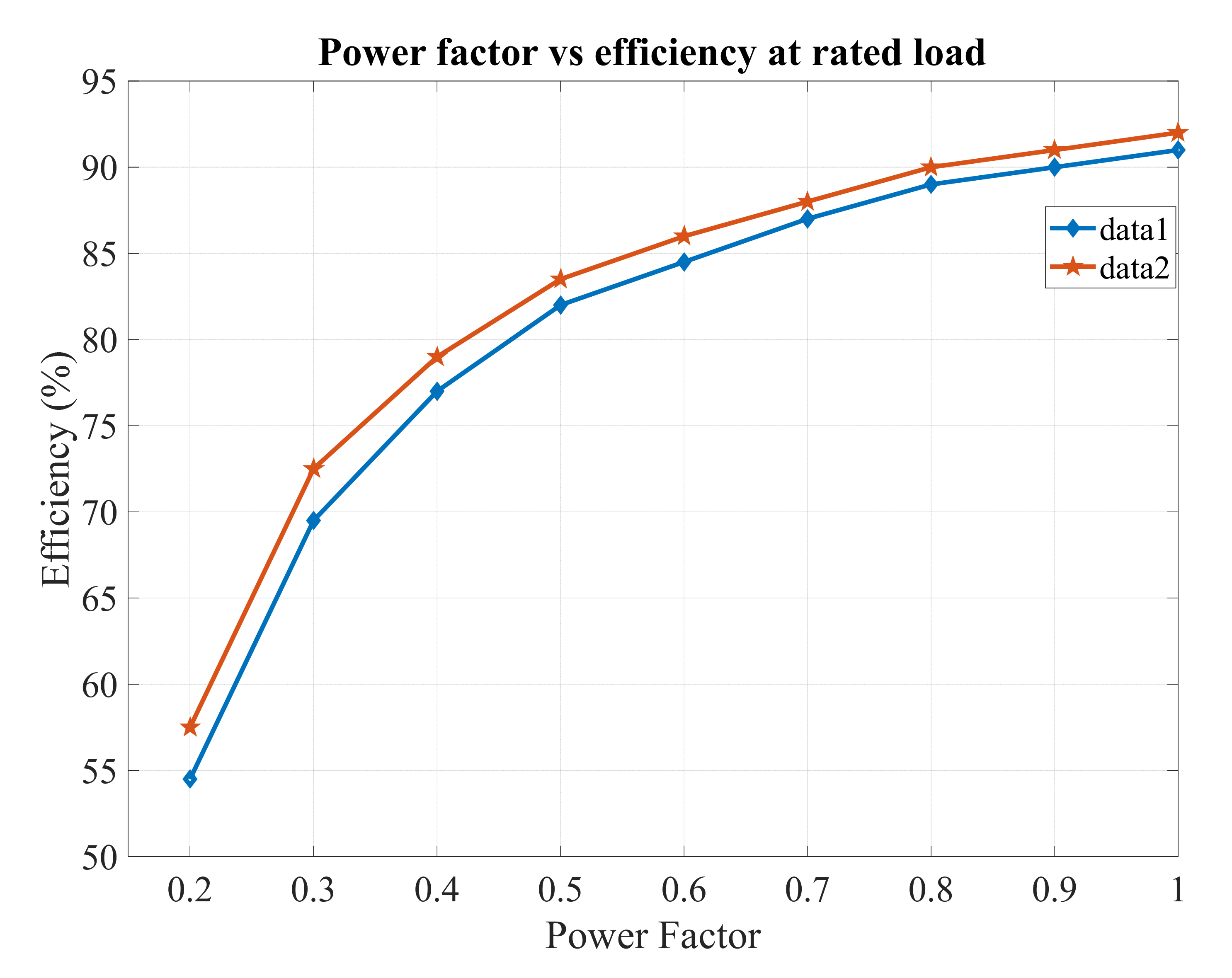
5. Validation and Experimental Results

The appropriate validation and experiential platform are necessary to demonstrate the effectiveness of the multi-phase transformer system under various unbalanced voltage and load conditions. Several experiments were carried out and reported in the literature to verify the conceptual design of phase transformation by a multi-phase transformer [5,6,7,20,24,46,52].

5.1. Experiment 1

In [5], a 2 kVA, 220 V/phase prototype multi-phase (three to seven) transformer was designed with the 1:1 transformation ratio. The underlying design concept was the same as discussed in Section 2.1.3. The transformer secondary was connected to star-connected seven-phase resistive and inductive loads, indicating 25 Ω and 60 mH, respectively. The input voltage was balanced by providing a three single-phase autotransformer to the primary winding of the transformer. The secondary voltages are taken on Yokogawa four-channel digital oscilloscope. Due to channel limitations, two separate plots were taken as shown in Figure 20a. It can be seen from the plot that each seven-phase has an equal phase difference that implies that a balanced seven-phase can be obtained from a balanced three-phase by employing this transformer.

5.2. Experiment 2

In another study [20], a novel seven-phase transformer was structured, and its conceptual design was discussed in 2.1.1. In this work, a seven-phase prototype transformer was configured with a capacity of 2 kVA, 220/220 Volts, 1:1 transformation ratio. A pentagon connected RL load was connected to the secondary side of the transformer. The secondary voltages were plotted on Yokogawa’s four-channel DSO. Due to channel limitations, two separate plots were taken as shown in Figure 20b. The first plot of Figure 20b consists of three separate phases and the current of one phase while the second plot shows the rest of the four phases. It is observed that a balanced three-phase can be utilized to develop equal phase difference in each phase for seven-phase output which suggests a high-performance accuracy of the proposed model.
The performance of the developed three-phase to seven-phase transformer is compared with the similar three-phase to three-phase transformer at rated load of different power factors. The comparison results are shown in Figure 21 [5]. It can be depicted from Figure 21 that a multi-phase transformer performance is better than a similar three-phase transformer. The efficiency of the multi-phase transformer during low power factor value remains higher compared to three-to-three phase transformation while during high power factor value, the efficiency of three-to-three-phase and three-to-seven-phase is closer.

6. Conclusions and Recommendations

In this review article, a comprehensive exploration of power conversion methods based on static multi-phase from a three or two-phase power supply is performed. Configuration of various transformation techniques for multi-phase transformation, advantages and disadvantages are discussed. Further, various configurations of multi-phase transformer systems along with different AI-based optimization techniques for the development of per-phase equivalent circuit modeling are reviewed and discussed thoroughly. This study outlines the different layouts that can convert a three- or two-phase system to any (n-phase) desired number of phases. As far as the multi-phase transformer is concerned, more research is available in the literature for three-phase to six-, nine-, or twelve-phase (multiple of three) systems. Nonetheless, information on a three-phase approach to an odd-phase (except multiples of three) such as five, seven, eleven, or thirteen conversion system is limited. This review has summarized, analyzed, and presented the development of the multi-phase transformers (e.g., five-phase, seven-phase, eleven-phase, and thirteen-phase). The issues concerning the impedance mismatch and hence unbalanced output voltages, especially at a low load, are explained. In addition, the challenges and problems related to various transformer fault analyses are discussed. Finally, potential research areas and possible applications of multi-phase transformers are highlighted. This review offers some selective future recommendations for further improvement mentioned below.
  • An in-depth comparative analysis of efficiencies between three-phase and multi-phase transformers is essential to be performed.
  • Thermal modeling of a transformer is performed to accurately predict winding and the component temperature rises above ambient temperature. Each phase of a multi-phase transformer winding comprises two or more windings. Connecting windings together may cause a local hotspot if not appropriately addressed. Therefore, advanced thermal modeling of a multi-phase transformer is necessary to examine the winding temperature, oil temperature, and local hotspot at the winding junction point.
  • The finite element method (FEM) is used to simulate the core losses of a transformer and investigate the flux density behavior in the transformer’s core. Hence, it is vital in the design process of a transformer, especially a multi-phase transformer. Substantial literature can be found for finite element analysis of a three-phase transformer. Different numbers of turns for each phase in a multi-phase transformer may create a spark at the junction or joint, leading to localized hotspots or discharge. A finite element analysis-based five-phase transformer design is presented in the literature but the study is limited to magnetics only. The same can be extended to all multi-phase transformers.
  • Further exploration related to the fault tolerance ability of the multi-phase conversion system can be carried out, which could lead to an increase in robustness and efficiency.
  • The multi-phase circuit breaker and electrical relay are significant in future research activities. Therefore, the execution of multi-phase circuit breakers and relay circuits in a multi-phase system needs to be further investigated.
The suggestions offered would provide valuable guidelines and solutions to the power engineers and researchers to develop advanced power conversion strategies towards future sustainable operation and management in various power and energy-related applications.

Author Contributions

Conceptualization, M.T., P.K.S., A.I. and M.A.H.; methodology, M.T., P.K.S., A.I. and M.A.H.; formal analysis, M.T., P.K.S., A.I. and M.A.H.; investigation, M.T.; resources, M.T.; data curation, M.T.; writing—original draft preparation, M.T. and M.A.H.; writing—review and editing, M.T., M.A.H., M.S.H.L., S.A.; visualization, M.T.; supervision, P.K.S. and A.I.; project administration, M.S.H.L.; funding acquisition, M.S.H.L. All authors have read and agreed to the published version of the manuscript.

Funding

This work was supported by the Universiti Kebangsaan Malaysia under Grant Code GP-2021-K023221. This work also received partial financial support from Universiti Kebangsaan Malaysia under Grant Code GGPM-2020-006.

Institutional Review Board Statement

Not applicable.

Informed Consent Statement

Not applicable.

Data Availability Statement

Not applicable.

Conflicts of Interest

The authors declare no conflict of interest.

References

  1. Parton, J.E. A general theory of phase transformation. Proc. IEEE Part. IV Inst. Monogr. 1952, 99, 12–23. [Google Scholar] [CrossRef]
  2. Levi, E. Multiphase electric machines for variable-speed applications. IEEE Trans. Ind. Electron. 2008, 55, 1893–1909. [Google Scholar] [CrossRef]
  3. Bruyère, A.; Semail, E.; Bouscayrol, A.; Locment, F.; Dubus, J.-M.; Mipo, J.-C. Modeling and control of a seven-phase claw-pole integrated starter alternator for micro-hybrid automotive applications. In Proceedings of the 2008 IEEE Vehicle Power and Propulsion Conference, Harbin, China, 3–5 September 2008; pp. 1–6. [Google Scholar] [CrossRef] [Green Version]
  4. Iqbal, A.; Ahmed, S.M.; Abu-Rub, H. Space vector PWM technique for a three-to-five-phase matrix converter. IEEE Trans. Ind. Appl. 2012, 48, 697–707. [Google Scholar] [CrossRef]
  5. Moinoddin, S.; Iqbal, A.; Abu-Rub, H.; Khan, M.R.; Ahmed, S.M. Three-phase to seven-phase power converting transformer. IEEE Trans. Energy Convers. 2012, 27, 757–766. [Google Scholar] [CrossRef]
  6. Iqbal, A.; Moinuddin, S.; Khan, M.R.; Ahmed, S.M.; Abu-Rub, H. A novel three-phase to five-phase transformation using a special transformer connection. IEEE Trans. Power Deliv. 2010, 25, 1637–1644. [Google Scholar] [CrossRef]
  7. Abdel-Khalik, A.; Shafik, Z.; Elserougi, A.; Ahmed, S.; Massoud, A. A static three-phase to five-phase transformer based on Scott connection. Electr. Power Syst. Res. 2014, 110, 84–93. [Google Scholar] [CrossRef]
  8. Tiwari, S.; Singh, G.; Bin Saroor, A. Multiphase power transmission research—A survey. Electr. Power Syst. Res. 1992, 24, 207–215. [Google Scholar] [CrossRef]
  9. Saleh, M.; Iqbal, A.; Kalam, A.; Abu-Rub, H. Carrier-based pulse width modulation technique for a three-to-five phase matrix converter for supplying five-phase two-motor drives. Int. J. Eng. Sci. Technol. 2010, 2, 67–78. [Google Scholar] [CrossRef] [Green Version]
  10. Chen, X. A three-phase multi-legged transformer model in ATP using the directly-formed inverse inductance matrix. IEEE Trans. Power Deliv. 1996, 11, 1554–1562. [Google Scholar] [CrossRef]
  11. Itoh, J.; Chiang, G.T.; Member, S.; Maki, K. Beatless synchronous PWM control for in a matrix converter. IEEE Trans. Power Electron. 2013, 28, 1338–1347. [Google Scholar] [CrossRef]
  12. Ahmed, S.M.; Abu-Rub, H.; Salam, Z.; Kouzou, A.; Ahmed, S.M.; Abdellah, K. Space vector PWM technique for a novel three-to-seven phase matrix converter. In Proceedings of the 39th Annual Conference of the IEEE Industrial Electronics Society (IECON 2013), Vienna, Austria, 10–13 November 2013; pp. 4949–4954. [Google Scholar] [CrossRef]
  13. Brandwajn, V.; Dommel, H.W.; Dommel, I.I. Matrix representation of three-phase N-winding transformers for steady-state and transient studies. IEEE Trans. Power Appar. Syst. 1982, 101, 1369–1378. [Google Scholar] [CrossRef]
  14. Khelafi, A.; Djebli, A.; Ouadah, M.; Touhami, O.; Ibtiouen, R. Control of five-phase induction machine with three-phase inverter via three-to-five phase transformer. In Proceedings of the 2020 International Conference on Electrical Machines (ICEM), Gothenburg, Sweden, 23–26 August 2020; pp. 2083–2089. [Google Scholar]
  15. Kim, D.; Ma, J.; Kim, J. Phase to phase interleaved method to reduce the common mode voltage for seven phase BLDCM drive. In Proceedings of the 2019 10th International Conference on Power Electronics and ECCE Asia (ICPE 2019—ECCE Asia), Busan, Korea, 27–30 May 2019; pp. 1–7. [Google Scholar]
  16. Reddy, B.P.; Meraj, M.; Iqbal, A.; Keerthipati, S.; Al-Hitmi, M. A single DC source-based three-level inverter topology for a four-pole open-end winding nine-phase PPMIM drives. IEEE Trans. Ind. Electron. 2021, 68, 2750–2759. [Google Scholar] [CrossRef]
  17. Reddy, B.P.; Meraj, M.; Iqbal, A.; Keerthipati, S.; Bhaskar, M.S. A hybrid multilevel inverter scheme for nine-phase PPMIM drive by using three-phase five-leg inverters. IEEE Trans. Ind. Electron. 2021, 68, 1895–1904. [Google Scholar] [CrossRef]
  18. Abdel-Khalik, A.S.; Massoud, A.; Ahmed, S. Standard three-phase stator frames for multiphase machines of prime-phase order: Optimal selection of slot/pole combination. IEEE Access 2019, 7, 78239–78259. [Google Scholar] [CrossRef]
  19. Khan, M.R.; Iqbal, A.; Ahmed, S.M.; Moinuddin, S.; Payami, S. Multi-phase alternative current machine winding design. Int. J. Eng. Sci. Technol. 2010, 2, 79–86. [Google Scholar] [CrossRef] [Green Version]
  20. Tabrez, M.; Sadhu, P.K.; Iqbal, A. A novel three-phase to seven-phase conversion technique using transformer winding con-nections. Eng. Technol. Appl. Sci. Res. 2017, 7, 1953–1961. [Google Scholar] [CrossRef]
  21. Djebli, A.; Touhami, O.; Ibtiouen, R. Configuration of three-phase to eleven-phase power transformer. In Proceedings of the 2018 International Conference on Electrical Sciences and Technologies in Maghreb (CISTEM), Algiers, Algeria, 28–31 October 2018; pp. 1–6. [Google Scholar]
  22. Mohammad, E.; Khan, F.; Bassel, H.; Iqbal, A.; Riyaz, A. Comparative analysis of three-phase to five-phase transformer connections. Aust. J. Electr. Electron. Eng. 2017, 14, 20–29. [Google Scholar] [CrossRef]
  23. Siafullah, P.; Iqbal, A.; Abu-Rub, H. Analytical and Graphical tool to analyse unbalanced five-phase system. Int. J. Recent Trends Eng. 2010, 3, 146–150. [Google Scholar]
  24. Tabrez, M.; Sadhu, P.K.; Iqbal, A.; Bakhsh, F.I. Analysis of a three-phase to seven-phase transformer under unbalanced input. Microsyst. Technol. 2020, 26, 2507–2516. [Google Scholar] [CrossRef]
  25. Karekar, S. A novel scheme of three to eleven phases transformer connection by using MATLAB software. J. Mater. Sci. 2018, 4, 555627. [Google Scholar] [CrossRef]
  26. Somashekar, B. A novel theory of three phases to eleven phases. Int. J. Recent Innov. Trends Comput. Commun. 2014, 2, 3828–3834. [Google Scholar]
  27. Razali, N.M.; Geraghty, J. Genetic algorithm performance with different selection strategies in solving TSP. In Proceedings of the World Congress on Engineering, London, UK, 6–8 July 2011; Volume II. [Google Scholar]
  28. Deepika, J.; Sujatha, B.C.; Singh, S.P. A novel design of three phase to thirteen phase power converting transformer. In Proceedings of the 2019 4th International Conference on Electrical, Electronics, Communication, Computer Technologies and Optimization Techniques (ICEECCOT), Mysuru, India, 13–14 December 2019; pp. 44–48. [Google Scholar]
  29. Dujic, D.; Levi, E.; Jones, M.; Grandi, G.; Serra, G.; Tani, A. Continuous PWM techniques for sinusoidal voltage generation with seven-phase voltage source inverters. In Proceedings of the IEEE Annual Power Electronics Specialists Conference, Puerto Varas, Chile, 4–7 December 2017; pp. 47–52. [Google Scholar]
  30. Ward, E.; Harer, H. Preliminary investigation of an inverter-fed 5-phase induction motor. IEEE Proc. 1969, 116, 980–984. [Google Scholar]
  31. El-Kahel, M.; Olivier, G.; Guimaraes, C.; April, G.E. Five and seven-phase converter transformers. In Proceedings of the Canadian Conference on Electrical and Computer Engineering (CCECE), Montreal, QC, Canada, 5–8 September 1995; pp. 708–711. [Google Scholar]
  32. El-Kahel, M.; Olivier, G.; Ba, A.O. Five and seven-phases converters: A feasibility study. In Proceedings of the Canadian Conference on Electrical and Computer Engineering (CCECE), Calgary, QC, Canada, 26–28 May 1996; pp. 1000–1003. [Google Scholar]
  33. Yan, X.Q.; Xu, Z.Y.; Wen, A.; Yang, Q.X. Fault analysis principle for twelve-phase transmission system. In Proceedings of the 2012 IEEE Power and Energy Society General Meeting, San Diego, CA, USA, 22–26 July 2012; pp. 1–6. [Google Scholar]
  34. Dorazio, T. High phase order transmission. In Proceedings of the 1990 IEEE Southern Tier Technical Conference on Southern Tier, Binghamton, NY, USA, 25 April 1990; pp. 31–36. [Google Scholar]
  35. Xu, P.; Wang, G.; Li, H.; Liang, Y.; Zhang, P. A new method for open conductors fault calculation of four-parallel transmission lines. In Proceedings of the 2010 Asia-Pacific Power and Energy Engineering Conference, Chengdu, China, 28–31 March 2010; pp. 1–4. [Google Scholar]
  36. Stewartand, J.R.; Wilson, D.D. High phase order transmission—A feasibility analysis—Part-I: Steady state considerations. IEEE Trans. Power A Syst. 1978, 97, 2300–2307. [Google Scholar] [CrossRef]
  37. Koley, E.; Jain, A.; Thoke, A.S.; Jain, A.; Ghosh, S. Detection and classification of faults on six phase transmission line using ANN. In Proceedings of the 2011 2nd International Conference on Computer and Communication Technology (ICCCT-2011), Allahabad, India, 15–17 September 2011; Volumes 15–17, pp. 100–103. [Google Scholar]
  38. Kant, P.; Singh, B. A new three-phase to five-phase transformer with power quality improvement in hybrid-multilevel inverter based VCIMD. IEEE Trans. Power Deliv. 2020, 35, 871–880. [Google Scholar] [CrossRef]
  39. Chandramohan, K.; Padmanaban, S.; Kalyanasundaram, R.; Bhaskar, M.S.; Mihet-Popa, L. Grid synchronization of a seven-phase wind electric generator using d-q PLL. Energies 2017, 10, 926. [Google Scholar] [CrossRef] [Green Version]
  40. Al-Ammari, R.; Iqbal, A.; Khandakar, A.; Rahman, S.; Padmanaban, S. Systematic implementation of multi-phase power supply (three to six) conversion system. Electronics 2019, 8, 109. [Google Scholar] [CrossRef] [Green Version]
  41. Riad, N.; Anis, W.; ElKassas, A.; Hassan, A. Three-phase multilevel inverter using selective harmonic elimination with marine predator algorithm. Electronics 2021, 10, 374. [Google Scholar] [CrossRef]
  42. Kesbia, N.; Schanen, J.-L.; Alawieh, H.; Garbuio, L.; Avenas, Y. Design by optimization of multiphase inverter for electric vehicle drive. In Proceedings of the 2020 22nd European Conference on Power Electronics and Applications (EPE’20 ECCE Europe), Lyon, France, 7–11 September 2010; IEEE: Piscataway, NJ, USA, 2020; pp. 1–8. [Google Scholar]
  43. Booin, M.B.; Cheraghi, M. THD minimization in a five-phase five-level vsi using a novel SVPWM technique. In Proceedings of the 2019 10th International Power Electronics, Drive Systems and Technologies Conference (PEDSTC), Shiraz, Iran, 12–14 February 2019; IEEE: Piscataway, NJ, USA, 2019; pp. 285–290. [Google Scholar]
  44. Razali, Noraini Mohd. "An efficient genetic algorithm for large scale vehicle routing problem subject to precedence constraints. Proc. Soc. Behav. Sci. 2015, 195, 1922–1931. [CrossRef] [Green Version]
  45. Warathe, S.; Patel, R.N. Six-phase transmission line over current protection by numerical relay. In Proceedings of the 2015 International Conference on Advanced Computing and Communication Systems, Coimbatore, India, 5–7 January 2015; pp. 1–5. [Google Scholar]
  46. Khan, M.R.; Alammari, R.; Moinoddin, S.; Iqbal, A. Modelling and analysis of a three-phase to five-phase transformer. Int. J. Emerg. Electr. Power Syst. 2014, 15, 401–410. [Google Scholar] [CrossRef]
  47. Yusoff, N.A.M.; Karim, K.A.; Ab Ghani, S.; Sutikno, T.; Jidin, A. Multiphase transformer modelling using finite element method. Int. J. Power Electron. Drive Syst. IJPEDS 2015, 6, 56. [Google Scholar] [CrossRef] [Green Version]
  48. Huang, J. Transformer and Method of Generating Multiple Multiphase Output Signals. USA Patent Application 16/417,204, 26 November 2020. [Google Scholar]
  49. Gao, Z.; Liu, X. An overview on fault diagnosis, prognosis and resilient control for wind turbine systems. Processes 2021, 9, 300. [Google Scholar] [CrossRef]
  50. Pillay, P.; Manyage, M. Definitions of voltage unbalance. IEEE Power Eng. Rev. 2001, 21, 49–51. [Google Scholar] [CrossRef]
  51. Tabrez, M.; Bakhsh, F.I.; Hassan, M.; Shamganth, K.; Al-Ghnimi, S. A comparative simulation study of different sensorless permanent magnet synchronous motor drives using neural network and fuzzy logic. J. Intell. Fuzzy Syst. 2018, 35, 5177–5184. [Google Scholar] [CrossRef]
  52. Tabrez, M.; Iqbal, A.; Sadhu, P.K.; Husain, M.A.; Bakhsh, F.I.; Singh, S.P. Equivalent circuit modelling of a three-phase to seven-phase transformer using PSO. J. Intell. Fuzzy Syst. 2021, in press. [Google Scholar] [CrossRef]
  53. Yang, Z.; Chen, Y. Interturn Short-Circuit Fault Detection of a Five-Phase Permanent Magnet Synchronous Motor. Energies 2021, 14, 434. [Google Scholar] [CrossRef]
  54. Toader, D.; Vintan, M.; Solea, C.; Vesa, D.; Greconici, M. Analysis of the Possibilities of Selective Detection of a Single Line-to-Ground Fault in a Medium Voltage Network with Isolated Neutral. Energies 2021, 14, 7019. [Google Scholar] [CrossRef]
  55. Wang, M.; Vandermaar, A.J.; Srivastava, K.D. Review of condition assessment of power transformers in service. IEEE Electr. Insul. Mag. 2002, 18, 12–25. [Google Scholar] [CrossRef]
  56. Alsuhaibani, S.; Khan, Y.; Beroual, A.; Malik, N.H. A review of frequency response analysis methods for power transformer diagnostics. Energies 2016, 9, 879. [Google Scholar] [CrossRef] [Green Version]
  57. Liang, X.; Liu, J.; Li, H.; Zhao, B.; Li, C.; Zuo, X. An Analytical Method for Pulse Transformer-Based Inductive Pulsed Power Supply Circuit. IEEE Trans. Appl. Supercond. 2021, 31, 1–4. [Google Scholar] [CrossRef]
  58. Duval, M. A review of faults detectable by gas-in-oil analysis in transformers. IEEE Electr. Insul. Mag. 2002, 18, 8–17. [Google Scholar] [CrossRef] [Green Version]
  59. Hannan, M.A.; Ker, P.J.; Lipu, M.S.H.; Choi, Z.H.; Rahman, M.S.A.; Muttaqi, K.M.; Blaabjerg, F. State of the Art of Solid-State Transformers: Advanced Topologies, Implementation Issues, Recent Progress and Improvements. IEEE Access 2020, 8, 19113–19132. [Google Scholar] [CrossRef]
  60. Almaguer, J.; Cárdenas, V.; Espinoza, J.; Aganza-Torres, A.; González, M. Performance and Control Strategy of Real-Time Simulation of a Three-Phase Solid-State Transformer. Appl. Sci. 2019, 9, 789. [Google Scholar] [CrossRef] [Green Version]
Figure 1. A basic k-limbed multi-phase transformer.
Machines 10 00013 g001
Figure 2. Representation of a phasor diagram for two-phase to n-phase transformation.
Machines 10 00013 g002
Figure 3. Schematic diagram of three-phase to n-phase transformation.
Machines 10 00013 g003
Figure 4. Phasor diagram of an n-phase system.
Machines 10 00013 g004
Figure 5. Configuration 1 for a three-phase to the five-phase transformer.
Machines 10 00013 g005
Figure 6. Configuration 2 for a three-phase to the five-phase transformer.
Machines 10 00013 g006
Figure 7. Configuration 3 for a three-phase to the five-phase transformer.
Machines 10 00013 g007
Figure 8. (a) Configuration 1 (b) Configuration 2 of the two alternative wiring diagrams for a three-phase to seven-phase transformer circuit.
Machines 10 00013 g008
Figure 9. Root mean square (RMS) error in the process of elimination of elements for matrix Mx (a). Stage 1, (b). Stage 2, (c). Final stage.
Machines 10 00013 g009aMachines 10 00013 g009b
Figure 10. (a) Three-phase input and output voltage waveforms of three-phase to (b) five-, (c) seven-, (d) eleven-, and (e) thirteen-phase transformers.
Machines 10 00013 g010aMachines 10 00013 g010b
Figure 11. Schematic block diagram of a wind energy conversion system (WECS)-based multi-phase IG.
Machines 10 00013 g011
Figure 12. Application of multi-phase transformer in power quality improvement.
Machines 10 00013 g012
Figure 13. (a) Efficiency comparison of 3–7 and 3–3 transformers. (b) Impedance mismatch of an n-phase system.
Machines 10 00013 g013
Figure 14. Exact equivalent circuit of the secondary windings.
Machines 10 00013 g014
Figure 15. Per-phase equivalent circuit of the secondary windings.
Machines 10 00013 g015
Figure 16. Flowchart of PSO applied for finding the best value of k.
Machines 10 00013 g016
Figure 17. PSO convergence characteristic results.
Machines 10 00013 g017
Figure 18. GA convergence characteristic results.
Machines 10 00013 g018
Figure 19. Per-phase equivalent circuit of the secondary side of the transformer.
Machines 10 00013 g019
Figure 20. The experimental results for unbalanced seven-phase output voltages (a) Seven-phase configuration 1 (b) Seven-phase configuration 2.
Machines 10 00013 g020
Figure 21. Efficiency comparison of a similar 3–7 phase transformer (data 1) vs. 3–3 phase transformer (data 2).
Machines 10 00013 g021
Table 1. Comparison of three-phase and seven-phase systems.
PropertiesThree-Phase MachineMulti-phase Machines
Torque ripple frequency (f-fundamental frequency)6f2nf(>6f)
Ordre of the lowest spatial mmf harmonics5 and 72n + 1
Power/Torque per-phase (P/Te)P/3(Te/3)P/n(Te/n)
Continues operation after an open-phase faultNot possible without modification of the power converter topologyContinuous post-fault operation but at reduced capacity
Torque enhancement by stator current harmonic injectionNot possibleYes (concentrated winding machines)
Transmission Line TowersHigher Tower Heights, Lower Tower Heights
Phase-to-Phase voltage at rated powerHigherLower
Magnetic Interference due to transmission lines and transposition requirementsHigherLower
Current/ConductorP/3Vp (Vp is Phase Voltage)P/nVp (reduced as n > 3)
Table 2. Comparative analysis of different configurations for the application of three-phase to five-phase transformation.
ParametersConfiguration #1Configuration #2Configuration #3
Total Primary Turns387387387
Total Secondary Turns825648709
Total Turns121210351096
Primary Resistance (Ω)0.0530.0530.053
Secondary Resistance (Ω)0.0490.0380.042
Space required by primary (mm2)418418418
Space required by secondary (mm2)131010301126
Total space required (mm2)172814481544
Table 3. Turn ratios of the secondary windings.
WindingN2/N1WindingN2/N1WindingN2/N1
a1a20.1721b1b20.7854c1c20.5010
a3a41.000b3b40.5010c3c40.7854
a5a60.1721b5b60.9028c5c60.3404
a7a80.6505b7b80.3404c7c80.9028
a9a100.6505----
Table 4. Turn ratios of different windings.
α Axisβ Axis
a1a21--
b1b2+0.6234b3b4+0.7818
c1c2−0.2225c3c4+0.9749
d1d2−0.9009d3d4+0.4338
e1e2−0.9009e3e4−0.4338
f1f2−0.2225f3f4−0.9749
g1g2+0.6234g3g4−0.7818
Table 5. Configuration of various transformation techniques for multi-phase transformation.
ReferencesConfigurationTransformation TechniquesPrimary Connection Secondary ConnectionAdvantagesDisadvantages
[1,7,20] m-Phase to n-Phase Transformation-Two-Phase to n-Phase Transformation-Scott-Star or Delta alike -Design is simple and straightforward.-Unbalance in input as well as output side.
[21]-Optimized Three-Phase to n-Phase transformation -Star or Delta-Star or Delta alike -Winding materials used are minimized using optimization technique.-Winding design is lengthy and cumbersome.
[5,6]-Phasor Algebra-based three-Phase to n-Phase Transformation -Star-Star or Delta alike -No primary side unbalance.-Winding design is complex.
[22]Three-Phase to Five-Phase Transformation-Configuration 1-Star-Star-Simple configuration.-Copper requirement is high.
[6,22]-Configuration 2-Star-Star-Most economical design.-Unbalance in input as well as output side.
[7,22]-Configuration 3-Star-Star -Copper requirement is high.
[5]Three-Phase to Seven-Phase Transformation-Configuration 1-Star-Star-No primary side unbalance.-Winding design is difficult.
[20]-Configuration 2-Scott-Star-Copper requirement is less.-Unbalance in primary as well as secondary side.
[21,25,26]Other High Phase Order Systems-Three-Phase to Eleven-Phase System-Star-Star-Less number of windings required.-Winding design is complicated as an optimization technique is used.
[28]-Three-Phase to Thirteen-Phase Transformer-Star-star-No primary side unbalance.-Winding design is lengthy and cumbersome.
Table 6. Transformer rectifier unit (TRU) pulses three- and seven phases in a single cycle.
Three PhasesSeven Phases
Transformer ConnectionNumber of Pulses in a CycleTransformer ConnectionNumber of Pulses in a Cycle
Half wave (Star)3Half wave (Star)7
Center tapper T/F6Center tapper T/F14
Y–Y and Y–Δ12Star–star and star–heptane28
---------18---------42
---------24---------56
---------48---------112
Table 7. Sequence network nomenclature.
Serial NumberFive-Phase SystemSeven-Phase System
1Positive SequenceAdjacent Positive Sequence
2Adjacent Negative Sequence Adjacent Negative Sequence
3Nonadjacent Positive Sequence Nonadjacent1 Positive Sequence
4Nonadjacent Negative Sequence Nonadjacent1 Negative Sequence
5Zero SequenceNonadjacent2 Positive Sequence
6-Nonadjacent2 Negative Sequence
7-Zero Sequence
Table 8. Comparison of results among different per-phase equivalent circuit models.
TechniqueAttained Optimum Value of k Corresponding Value of Objective Function
GA1.23630.0972204
PSO1.23640.0972200
From Plot1.23600.0973
Table 9. Transformer fault testing methods and their applications.
Testing MethodsApplications
Thermal monitoringTransformer condition monitoring and assessment
Partial discharge measurements
dissolved gas analysis (DGA)
Tan δ and capacitance
Turns ratio, winding impedance and inductance measurement
Magnetizing current measurements
Thermal monitoring
Reactance measurement method
and low voltage impulse (LVI)
Winding deformations
Frequency Response Analysis (FRA)Short circuits
Loss of clamps
Inter-disk fault
Axial displacement
Dielectric test of transformer bushings and associated faults
Publisher’s Note: MDPI stays neutral with regard to jurisdictional claims in published maps and institutional affiliations.

