Article

Motion Law and Mechanical Properties of PIGs When Passing through a Pipe Bend

1
College of Naval Architecture and Ocean Engineering, Dalian Maritime University, Dalian 116026, China
2
Liaoning Provincial Key Laboratory of Rescue and Salvage Engineering, Dalian Maritime University, Dalian 116026, China
3
International Joint Research Centre for Subsea Engineering Technology and Equipment, Dalian Maritime University, Dalian 116026, China
*
Author to whom correspondence should be addressed.
Machines 2022, 10(10), 963; https://doi.org/10.3390/machines10100963
Submission received: 14 September 2022 / Revised: 13 October 2022 / Accepted: 19 October 2022 / Published: 21 October 2022
(This article belongs to the Special Issue Mobile Robotics: Mathematics, Models and Methods)

Abstract

:
Pipeline inspection gauges (PIGs), as a kind of pipeline robot, are very efficient tools for cleaning and inspecting pipelines. However, the occurrence of obstructions in PIGs has always been a problem. The main cause of the PIG clogging pipeline problem is the reduced pressure differential between the front and rear due to damage to the cup. In this paper, a rigid-flexible coupled multibody dynamic motion system is established by importing flexible bodies. The stress and contact force generated by the elastic deformation of the cup in the pipe are analyzed. Moreover, the spacing ratio of PIG cups and the number of cups were changed, the number of cabin sections was increased, the bending of PIGs of different sizes and specifications was studied, and the influence of the cross-universal joint on the bending of PIGs, as well as the force between the cups and the core tube, was analyzed. Through the design and construction of the corresponding experimental equipment, the influence of the change in the number of leather cups on cornering is studied.

1. Introduction

With the prolongation of the service life of oil and gas pipelines, different degrees of debris and impurities will adhere to the inner wall of the pipeline, resulting in reduced pipeline transportation efficiency and even pipeline blockage [1,2,3]. Therefore, we need to regularly inspect and clean the pipeline. PIGs are cost-effective pipe-cleaning devices, but the problem of blocked pipes with PIGs has always been difficult to solve [4,5,6]. Azpiroz et al. studied the effect of baffles on flow through PIGs in single-phase systems. An axisymmetric frame was used, where the PIG was assumed to move at a constant speed. Results were obtained for various parameter ranges, such as Reynolds number and bypass opening [7]. Kohda et al. proposed a method that could be used for flow rate and pressure analysis of two-phase flows [8,9].
Lin Wang et al. proposed that the dynamic response of the system was the cumulative effect of fluid-solid coupling and two-phase flow characteristics during pigging operations [10,11,12]. Xinyu Zhang et al. completed the friction evaluation and attitude analysis after pigging and proposed the theory of controlling PIG rotation [13]. To reduce vibration during pigging, Aksenov et al. proposed recommendations for inertial and stiffness parameters [14,15,16]. Lesani et al. derived and solved two- and three-dimensional kinetic equations for a small PIG through a liquid pipe, drawing on the equations of Saeedbakhsh [17]. The effect of the flow field on the PIG trajectory was investigated by using the bypass port in the PIG to synthesize the velocity controller of the PIG. The validity of the equations was also verified using simulations [18]. Since the material used for the cup was mostly polyurethane [19], in order to study the nonlinear dynamic vibration characteristics, Dongyan Shi et al. used the coupled Eulerian–Lagrangian approach to establish a fluid-structure interaction model of PIG in the pipeline. The friction force of the three-cup PIG and the influence of the local deformation area on the model were analyzed [20,21]. Yuguang Cao et al. employed a 3D fluid-structure interaction model to simulate the changes in PIG during the launching process, predicting the driving force and describing the mechanical behavior of the cup [22,23].
Azevedo et al. presented a simple porcine hydrodynamic model, analyzing foam PIGs, flat disks, and piston cups [24,25,26]. Solghar et al. solved the governing equation of the PIG. The model was used to measure the position and velocity changes in the PIG [27]. Esmaeilzadeh et al. combined the governing equation with the momentum equation to predict the motion state of the PIG with the help of the feature method and regular rectangular grid [28,29]. A two-fluid-based multiphase hydrodynamic model was developed by Ayala to predict the location of maximum liquid retention due to liquid condensation [30,31,32]. Durali et al. derived the pig/wall contact force using the finite element method and experimental results, and obtained the position, velocity, and pitch angle profiles of PIG and the pressure waves of the upstream and downstream fluids through the dynamic behavior at sinusoidal anomalies [33]. Tension lines were used to verify the numerical solution, which could be utilized to compare the numerical and analytical solutions of the polyurethane rubber and pipe wall steel interference problems. A discussion of the effect of the interference, thickness, and curvature of the spherical sealing disk on the stress-strain distribution at the outer edge of the cup bowl during PIG depression was followed. The vibration response due to collision between the running PIG and the ring weld was experimentally and theoretically investigated. A two-dimensional kinetic model of the PIG was introduced to explain and understand the collisional vibrations. The frictional and dynamic characteristics of the sealing disk of the PIG as it passed through the ring weld in the pipe were directly investigated using a bespoke experimental setup. The contact behavior between the sealing disk and the ring weld was analyzed using a finite element method [34,35,36,37]. In order to improve the efficiency of cleaning the pipes, Zheng Liang et al. were equipped with a braking unit on the PIG, which could provide stable speed [38,39]. Wenming Wang et al. discussed the detailed process of PIGs passing through the pipeline bend, establishing the pigging mechanics model of the shield section and analyzing the force on the elbow of the foam PIG [40,41]. Tao Deng et al. established a transient hydraulic model of the pigging process after the hydraulic test in the dual-net system, which combined the mass and motion equations of gas and liquid, and then solved it by the characteristic method. The gas-liquid flow pressure drops characteristics of T-sudden and curved drainpipes were studied. The transient water pressure after the water pressure test in the pigging process was calculated, and the state of the PIG and the water pressure pulsation value during the pigging process could be predicted [42,43].
Chang Liu et al. developed a finite element model of PIG operation in a bend, validated by a customized experimental setup, in which the effect of the friction coefficient on the PIG was discussed. From this analysis, three influencing factors, namely, the sealing performance, driving performance, and collision likelihood, were selected to describe the operating capability of the PIG. Based on a finite element model, five conditions with different coefficients of friction were calculated to derive the correlation between the influencing factors and the coefficient of friction and the driving capability in the bend under different levels of friction [44,45,46]. Predicting the contact force of a two-way PIG and comparing the results of linear and nonlinear simulations, a two-dimensional axisymmetric nonlinear finite element model was proposed by Xiaoxiao Zhu and Shimin Zhang. The effects of the excess of the cup bowl, the thickness of the cup bowl, the curvature of the cup bowl, and the contact size with the pipe wall on the contact force of the cup bowl at different differential pressures, and the effects on the performance of the linear and nonlinear models were also discussed. Simulations and experiments were carried out to verify the effect of the above four parameters on the deflection angle of the cup bowl [47,48,49]. Canavese et al. designed a plastic caliper PIG capable of detecting, locating, and determining internal diameter variations and roughness variations with ease of maintenance [50,51]. Nguyen et al. proposed a simple model of PIG passing through a 90° curved section of pipeline, simulating the motion state under two operating boundary conditions [52,53].
Under actual working conditions, damage to the leather cup will reduce the pressure difference between the front and rear of the PIG, which in turn causes the PIG to block the pipeline [54]. Lu Yang et al. explored the pressure distribution and pressure gradients around pipe blockages under different operating conditions. Three-dimensional fluid dynamics simulations in steady state were performed to examine the effects of blockage diameter, blockage length, and blockage location. The relationship between the pressure drops and blockage characteristics was predicted. Moreover, a predictive model for blockage sensing and localization was proposed. Laboratory experiments were conducted to compare the simulation results with measured data and to assess the accuracy of the prediction model [55,56]. Mishra et al. examined the details of a pipeline detector robot that could be used for cleaning and detecting leaks in off-road pipelines that contain crude oil flows in the buried pipelines [57].
Changlin Feng et al. analyzed the special mechanical characteristics and speed characteristics of the cross-axis universal joint, and obtained the force of the cross-axis universal joint [58,59]. At present, there are few studies, especially experimental studies, on PIG cornering at home and abroad. However, the problem of PIG bending and blocking in the pipeline has always existed. In this paper, the method of importing flexible bodies enables the simulation of multirigid mechanical systems to have flexible parts at the same time. This method mainly studies the motion law and mechanical properties of the PIG bending pipe, changes the spacing ratio of the PIG cups and the number of cups, increases the number of cabin sections, studies different PIG bending situations, and analyzes and determines the maximum stress of the cup during bending. If the leather cup is easily damaged during bending, the contact force is analyzed to determine the collision between the leather cup and the pipe, the influence of the cross-universal joint on the PIG bending, and the force between the leather cup and the core tube. Furthermore, the running speed is analyzed to determine the difficulty of the cornering process. Through the design and construction of the corresponding experimental equipment, the influence of the change in the number of leather cups in cornering is studied.

2. Materials and Methods

2.1. Equation of Motion

The forces on the PIG as it moves through the bend are shown in Figure 1.
F N means that the centrifugal force that the pipeline robot receives when it works in the elbow is also the resultant external force in the normal direction of the pipeline robot:
F N = m a n = m ω 2 R = m v 2 R
The term m is the mass of the pipeline robot, ω is the angular velocity of the pipeline robot, v is the linear speed of the pipeline robot, and R is the radius of curvature of the pipeline.
F T = K 0 ω t α + α 0
F z = c 0 ω
Δ F = P 1 P 2 = F T F z
F T is the equivalent elasticity, c 0 is the equivalent axial damping of the pipeline robot,   α 0 is the compressive deformation of the fluid, K 0 is the axial equivalent stiffness, c 0 is the equivalent axial damping of the pipeline robot, and α is the rotation angle change in the pipeline robot in the pipeline. F z is the equivalent axial damping force, and is the rotational angular velocity of the pipeline robot. The friction force acts on the leather cup, as shown in Figure 1, and its direction is tangent to the pipe wall; thus, this force is approximated as follows:
f = μ F N + N 1 + N 2 + Δ F = μ m ω 2 R + N 1 + N 2 + Δ F
For the sake of simplification, assuming that the frictional force of the front leather cup and the rear leather cup is the same, the following formula can be used:
F 1 = F 2 = 1 2 μ F N + N 1 + N 2 + Δ F
The above analysis leads to the following equations of motion for the pipeline robot:
K 0 ω t α + c 0 ω μ m ω 2 R + N 1 + N 2 + Δ F c o s   θ R = 1 12 m l 2

2.2. Experimental System

The main experimental equipment for the PIG bending experiment is shown in Table 1. The radius of the pipe is 25 mm, and the pipes are connected by flanges and sealing rings.
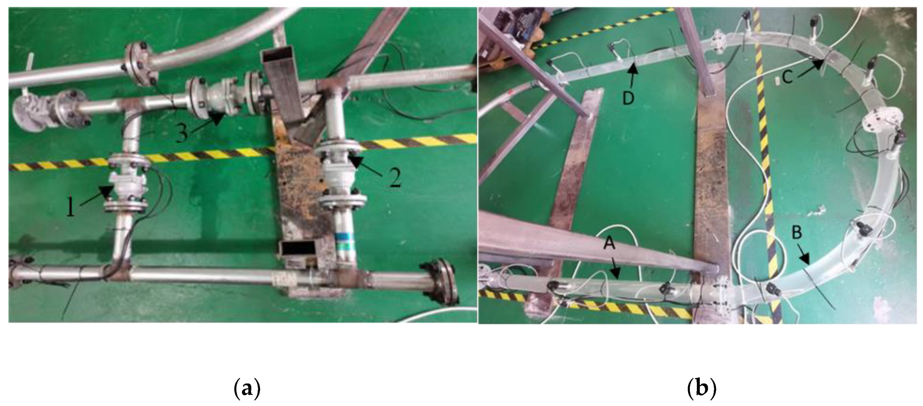
The serving system is shown in Figure 2a. The experimental process is as follows: the console is used to control the pump-to-pump water; Ball Valve 1 and Ball Valve 3 are closed; Ball Valve 2 is opened; the pipeline is initially filled with water; the PIG is placed in the pipeline with an iron rod; Ball Valve 2 is closed; and Ball Valve 1 and Ball Valve 3 are opened and driven with water pressure. The entire pipeline is divided into 4 observation areas A, B, C, and D, and each observation area corresponds to three observation points; that is, three pressure sensors are installed, as shown in Figure 2b. The sensor measures the differential pressures before and after the PIG is utilized, and the data are directly received by the console.

2.3. Effect of the Number of Leather Cups on PIG Cornering

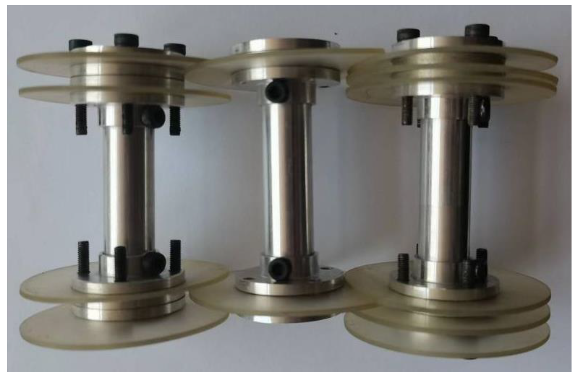
To verify the influence of the number of leather cups on PIG turning, the conventional PIG is now selected, and the number of leather cups is changed. The model is shown in Figure 3. The 2-cup, 4-cup, and 6-cup are run in the pipeline at the same flow and pressure. M3 screws are used to connect the inner flange of the PIG, the end cover, the cup, and the core tube. The overall mass of the PIG in a single cabin is 39.4 g, and its influence on cornering can be ignored due to the small mass of the PIG. The various parts and dimensions of the PIG are shown in Table 2.
The PIG velocity is calculated by observing the time at which the point pressure value changes. After the water is passed through the pipeline, the pressure is 0.007 MPa. Six cups of PIG are placed into the pipeline to run, and the pressure sensor shows that the pressure in the pipeline rises to approximately 0.020 MPa. The pressure images of the PIG passing through each observation area are shown in Figure 4.
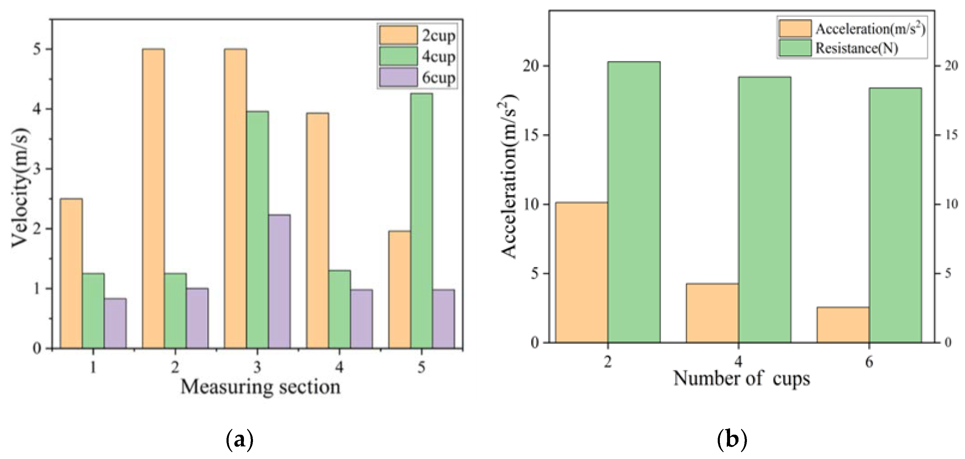
The straight pipes and curved pipes in the AB area are selected for specific analysis. By calculating the time for the PIG to pass through the pressure sensor, the speed of each node is calculated as shown in Figure 5a, and the average acceleration is calculated by the formula:
a = v t + Δ t v t Δ t
The average acceleration of the elbow section is calculated and the resistance of the PIG with different numbers of cups when bending is calculated according to Newton’s second law. The results are shown in Figure 5.
As shown in Figure 5, the PIG of the two cups passes the 4th sensor at a speed of 5 m/s, passes through the 6th sensor after 0.3 s, and decelerates to 1.96 m/s. The acceleration is −10.13 m/s2, which is the minimum, while the resistance is at its maximum. The PIG of four cups passes through the 4th sensor at 3.96 m/s, passes through the 6th sensor after 0.7 s, decelerates to 0.98 m/s, and the acceleration is −4.26 m/s2. In addition, the PIG of six cups passes at 2.23 m. After the PIG passes through the 4th sensor, it passes through the 6th sensor after 0.8 s, decelerates to 0.98 m/s, and the acceleration is −1.56 m/s2 which is the maximum. The two-cup PIG has the fastest running speed in the whole process and the smallest bending acceleration, and the contact force between the cup and the pipe wall is the largest during bending; the 6-cup PIG runs the slowest in the whole process and has the largest bending acceleration. Moreover, the indirect contact force is minimal. According to Equation (5), it can be obtained that the two-cup PIG receives the most friction and wears the most severely during cornering. As shown in Figure 5b, acceleration and resistance are negatively correlated with the number of leather bowls. There is a large decrease in acceleration compared to resistance.

3. Results

In practical engineering, the structure of the PIG greatly affects the occurrence of obstructions in PIGs. For example, the spacing ratio of the PIG, the number of cups, the length of the universal joint, and the number of sections of the PIG detection cabin change. To objectively and accurately explore the motion of PIG in the pipeline and solve the problem of PIG passing through the curved pipeline, carrying out dynamic simulations is necessary to study its motion law, mechanical characteristics, dynamic torque-resistance torque conversion process, and power transmission mechanism.

3.1. Effect of Changing the Number of Leather Cups on PIG Cornering

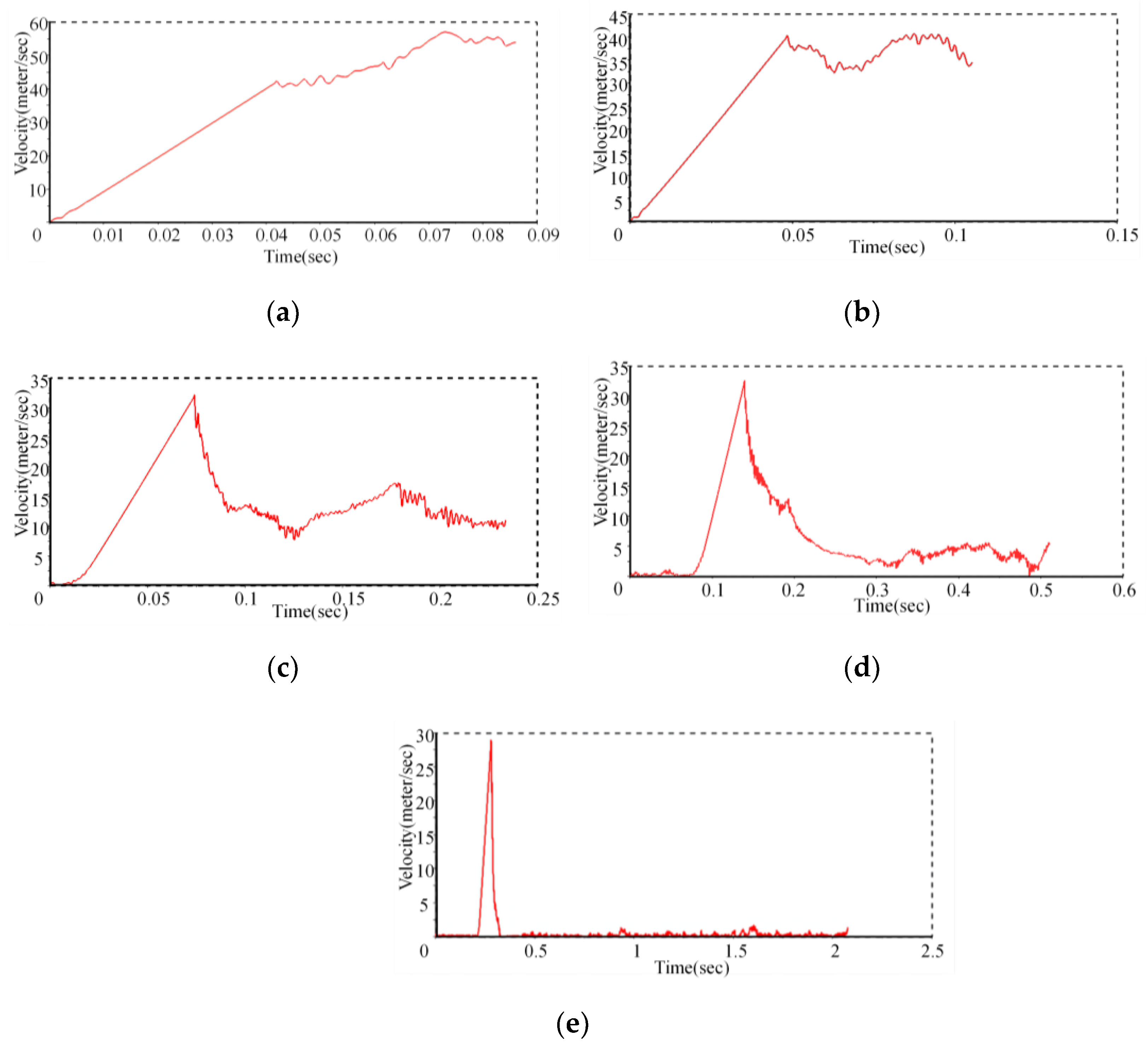
Conventional PIG is generally equipped with leather bowls, including butterfly leather bowls, straight leather bowls, and special leather bowl shapes that can also be created according to different needs. Generally, 2–8 leather cups are installed on each section of the PIG to perform different functions, such as driving and cleaning, and occasionally, there will be an odd number of leather cups. Changing the number of PIG cups to study the influence of different numbers of cups on the motion characteristics and motion law of PIG cornering is helpful to improve the blocked pipelines of PIGs. The number of leather cups determines the quality of the PIG effect and the movement effect of the entire PIG. The number of PIG cups was changed to 2, 3, 4, 6, and 8, and the results were analyzed after simulation. The speed comparison images of the number of leather cups are 2, 3, 4, and 6, as shown in Figure 6.
As shown in Figure 6, when the number of cups increases, the maximum speed of the PIG before cornering will decrease, and the average speed during cornering will also decrease. This is due to the increase in the frictional force after increasing the leather cup, resulting in an exponential decrease in the speed of the PIG movement for each additional cup. The number of leather cups can easily cause blockage. The stress cloud diagram of the leather cup is shown in Figure 7.
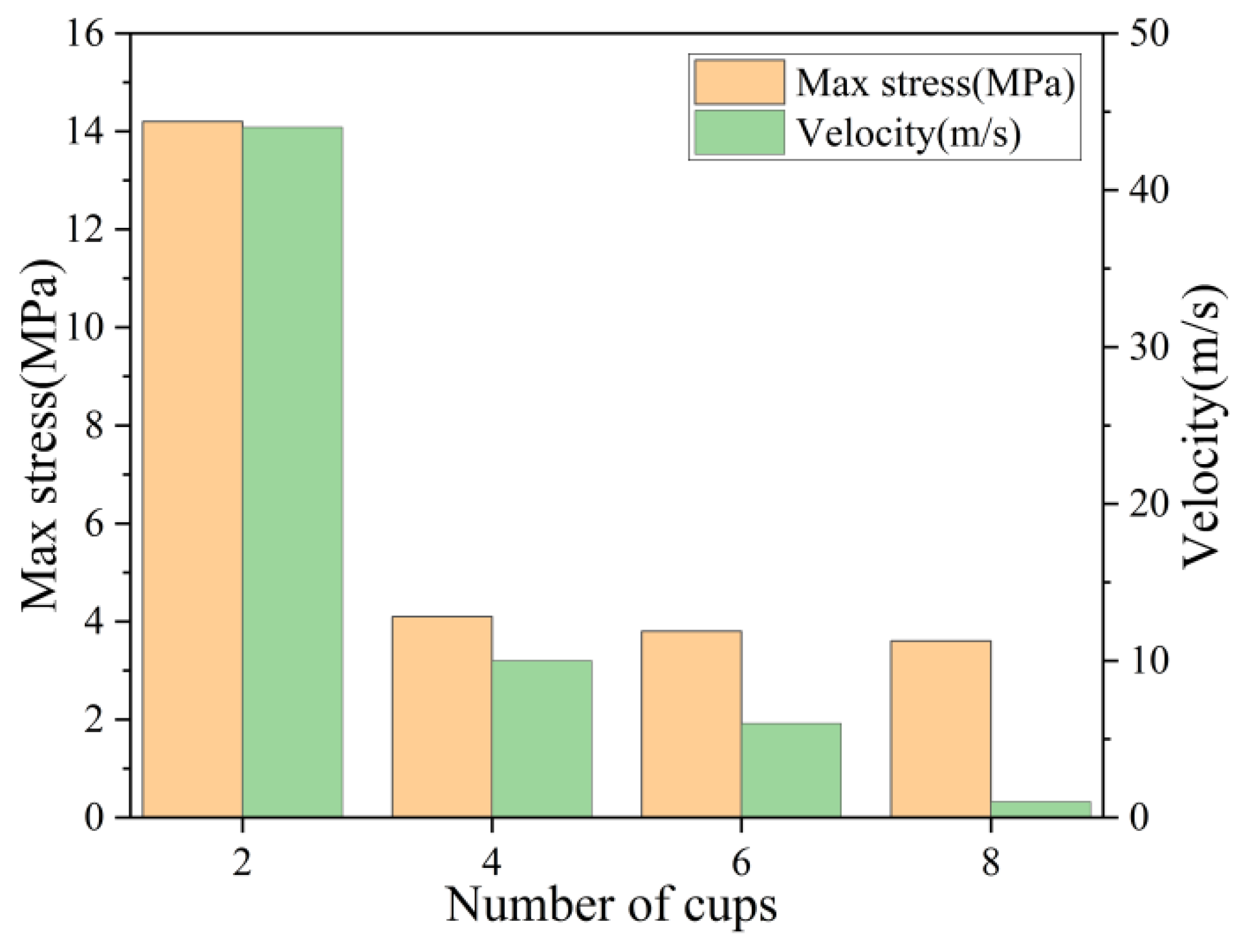
The leather cup is introduced into the flexible body, and the driving pressure is provided after water passes through the pipe inlet. The maximum pressure generated by the PIG is due to the contact force between the leather cup and the pipe wall during the bend. The red area indicates the position of the maximum pressure. In practice, the maximum stress is at the center of the contact surface, the direction of the force is perpendicular to the contact surface of the cup, and the contact area between the cup and the tube wall is much smaller than the area of the cup. Figure 8 shows the comparison of the maximum stress and speed of different cup PIGs when cornering.
The speed of the cup will make the collision between the cup and the tube wall more intense when cornering, and the maximum stress on the cup will be greater. When the leather cup PIG is bent, the stress is concentrated on the upper half, and the excessive speed causes excessive stress at the connection between the leather cup and the core tube, which causes the leather cup to be damaged. However, the PIG of the four cups is very stable when cornering, and the stress size and stress distribution shown in the figure will not cause the cups to be damaged during movement. In fact, during the entire movement of the PIG, injecting air is necessary to maintain the pressure difference before and after the PIG so that it can keep moving at a uniform speed as much as possible and reduce the damage to itself and the pipeline caused by the PIG speed being too fast. In addition, the injection of air will reduce the maximum stress generated by the cup when cornering.
The results show that the PIG speed of the two leather cups is the fastest when compared with other PIGs and also shows a tendency to accelerate in the process of turning up to 50 m/s. However, the stress on the leather cups is also the largest, and the maximum stress reaches 10 MPa, which can easily cause damage to the PIG cups. When damaged, the eight leather cups of a PIG have the lowest speed when cornering, which affects the overall ability to avoid obstructions in PIGs. The 4-cup PIG and the 6-cup PIG are relatively good in terms of speed and stress. The speed of the leather cup PIG can be maintained at 5 m/s during cornering. The maximum stress is also below 3.7 MPa, and the entire cornering process is relatively smooth. The speed of the 6-cup PIG is smaller than that of the 4-cup PIG, at approximately 3 m/s, but the maximum stress is also smaller than that of the 4-cup PIG; thus, the 4-cup PIG can be given priority. The 6-cup PIG can improve the situation of cup wear and cause the PIG to block the pipeline.

3.2. The Effect of the Cup Spacing Ratio on PIG Cornering

The cup spacing ratio is the ratio of the distance between the two cups to the length of the entire PIG. The material property of the leather bowl was set to polyurethane, and the other materials were set to structural steel. The leather cup, flange, and core pipe were fixed, and the motion pair between the PIG and the pipe was set as a cylindrical pair. The friction coefficient is changed to 0.2, and the pressure is changed to the corresponding force on the PIG. The contact between the cup and the PIG is set, and the restitution method is used. By changing the spacing ratio between the PIG cups, the effect of the ratio of the spacing between the cups to the length (L) of the PIG on the running speed is shown in Figure 9. The spacing ratio between the cups is the most easily overlooked structural change. The distance between the two cups not only determines the PIG effect but also poses a certain risk for the PIG-PIG to block the pipe.
When the leather cup spacing ratio is 3%, the running speed is the fastest, the speed is maintained at 30 m/s when cornering, and the acceleration is the largest. The leather cup interval accounts for 10% of PIG. The resistance is large when cornering, the acceleration is the smallest, the cornering speed is 5 m/s, the speed slowdown is serious, and jamming easily occurs. When the cup spacing ratio is between 7% and 8%, the cornering speed is approximately 10 m/s, and the acceleration is relatively small. Under complex pipeline environmental conditions, the PIG mainly moves through the pressure difference generated by the cup and the role of support. In the process of contacting the inner wall of the pipeline, the polyurethane rubber material is in contact with the inner wall of the pipeline due to its superelasticity. The PIG has good straight pipe and curve passing performance. Due to the existence of working conditions, such as pipe elbows, pipe diameter reduction, bending deformation, and welding point deformation, the ability of PIGs to pass is severely restricted. Figure 10 shows the maximum stress of the PIG with different cup spacing ratios when bending.
When the leather cup interval ratio is 3%, the running speed is the fastest, and the speed is maintained at 30 m/s when cornering. However, the PIG leather cup with a leather cup interval ratio of 3% is subject to a maximum stress of 9 MPa, which will cause serious damage to the leather cup. The leather cup interval accounts for 10% of the PIG, and the resistance is large when cornering, which easily causes jamming, and the speed sharply slows down. When the leather cup interval accounts for 7% of the PIG length ratio, the speed is moderate and can be maintained at 7 m/s, and the maximum stress below 5 MPa is better than that of other PIGs. Therefore, when we choose PIGs for cornering, we can choose the ratio of the leather cup interval to 7% of the PIG length so that the cornering speed is moderate, and the maximum stress is more suitable than other PIGs, which does not easily cause the wear of the leather cup and makes the corners difficult to bend. Thus, the ability to pass through is stronger.

3.3. Analysis of the Cornering Characteristics of Double-Cabin PIGs

To meet the engineering needs of maintenance and emergency disposal of submarine pipelines, multicabin PIGs are often used for pipeline cleaning, defect detection, emergency plugging, and other operations. For multicabin PIG cornering, the influence of the entire PIG kinematic characteristics and mechanical properties was studied, and the influence of the force on the cup during PIG cornering and the force transmission of the cross-universal coupling in the double-cabin PIG cornering were analyzed. The force generated between the cup and the core tube and the influence of the change in the friction coefficient on the PIG bending will help solve the problem of clogging in the pipe when the PIG is bending. The simulation parameters were set to be consistent with the PIG driving pressure, friction coefficient, and material parameters of a single cabin, and the PIG cornering speed was observed. The results are shown in Figure 11.
The average speed of double-stage PIG cornering is 2.5 m/s, while the average speed of single-stage PIG cornering is 20 m/s. The speed of double-segment PIG cornering is much lower than that of single-segment PIG cornering. According to the force formula of PIG motion:
P 1 P 2 A p i g F f F w ± G s i n α = m d v p i g d t
The increase in the number of cabins results in an enhanced mass, and at the same time, the number of cups doubles, the frictional resistance will increase, and the speed of the PIG movement will be seriously reduced. In addition, the bending speed is affected, which reduces stability. Therefore, in practical engineering, multicabin PIGs need to be equipped with independent power systems and real-time monitoring of the working position and movement of PIGs to prevent pipeline blockage during work.
In the coupling between the two sections of the PIG, the driving yoke rotates the driven yoke through the cross shaft, and the force transmission direction of the contact between each two is in the plane perpendicular to the shaft and rotates. Regardless of the deviation between actual machining and installation, force action and energy consumption will also occur between the driving fork and the driven fork during the cornering process, which in turn affects the movement speed and force of the PIG. The mechanical formula of the coupling is as follows:
T 1 = 2 R F 1 = 2 R F 1 s i n β 1 t g α
The cross-universal joint will generate additional torque during operation, and the force at each bearing will also be affected in the process of transmitting the force. According to the simulation results of the double-cabin PIG cornering, the force of the cross-universal joint is shown in Figure 12.
As seen from Figure 12, the forces between the universal joints are basically uniform throughout the movement process, and these forces will cause energy loss, which will reduce the speed of the PIG. At certain moments, the force between the driving fork and the driven fork suddenly increases, which will also cause the force transmitted from the first cabin to the second cabin to suddenly change, which will cause the second cabin to interact with the pipeline. The collision between them becomes intense, which causes the stress of the cup to increase, and the cup and the pipe are out of contact, which affects the movement of the entire PIG.
Increasing the number of compartments not only has a great impact on the running speed but also has a great impact on the contact force between the cup and the pipe and the maximum stress during operation. Thus, the formula of the stress is described as follows:
σ = N S
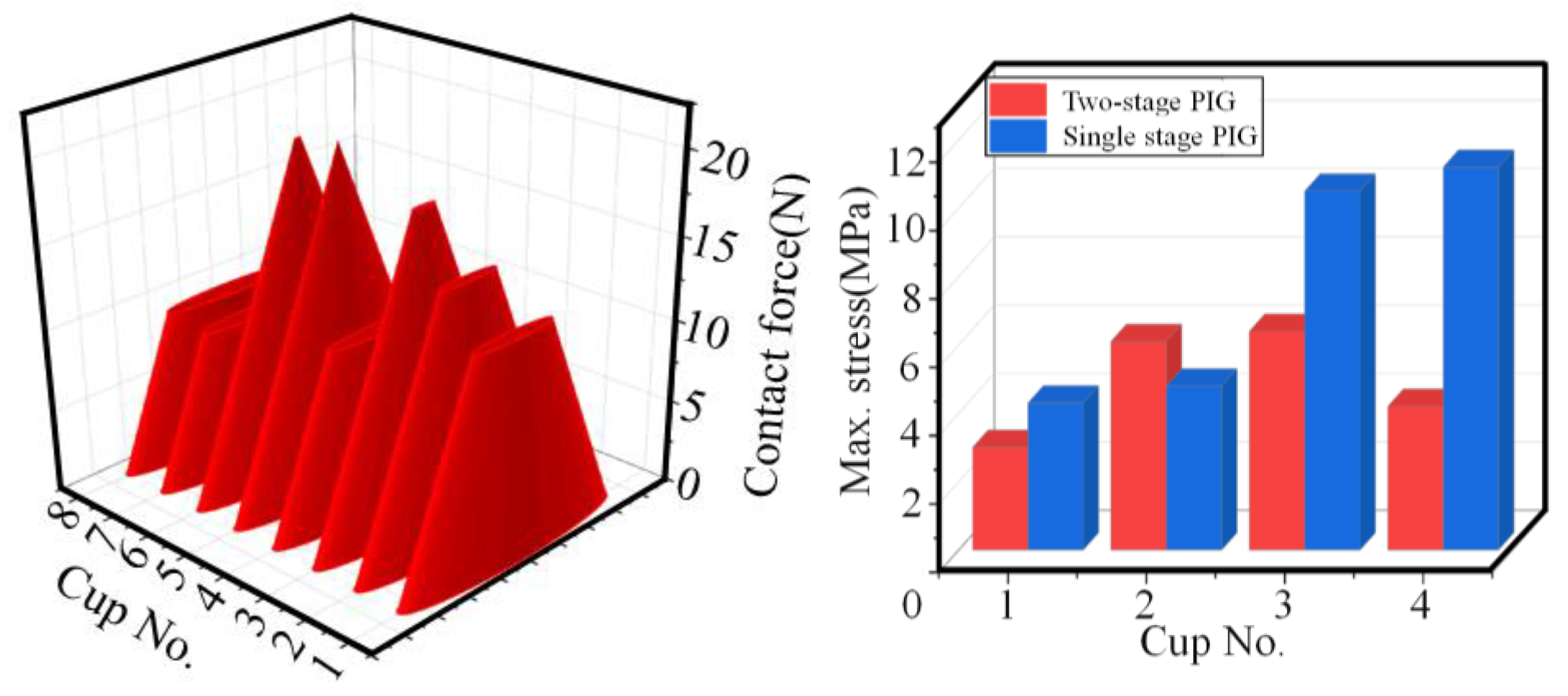
Due to the fast-running speed of the single-cabin PIG, the contact area between the cup and the pipe wall is larger when they are in contact with the pipe wall, and the elastic resistance of the pipe wall to the cup will increase, resulting in a larger maximum stress. In the early years, some scholars regarded the edge deformation of the cup as a cantilever beam and used the formula for calculating the deformation of the cantilever beam to estimate the contact force between the cup and the pipe. However, the nonlinear deformation of the sealing disk is complex, and the assumption based on linear deformation is not enough to describe and characterize the superplastic deformation of the cup. The method of importing flexible bodies can effectively measure the stress. Figure 13 shows the comparison between the contact force of the PIG cups in the double cabin and the maximum stress results of the first four cups in the single cabin.
The contact force and the maximum stress between the cup and the pipe wall are mainly caused by the change in gravity and the decrease in the running speed after the number of cabins is increased. The contact force on the leather bowl caused by PIG gravity is:
d F N = d G s i n φ = G c o s γ s i n φ 2 π N d φ
F N = 0 2 π G c o s γ s i n φ 2 π N d φ = 0
After the increase in gravity, the contact force caused by gravity will increase, the friction force and the resistance in the horizontal direction will increase, and the PIG speed will decrease. The increase in the number of PIG segments increases the number of the leather cups, relieves the impact when cornering, and reduces the maximum stress of the leather cups. Therefore, when using the dual-cabin PIG for cornering, the damage to the leather cup is decreased to a certain extent, the stability of the front and rear pressure difference is ensured, and the service life of the leather cup is increased. Thus, more importantly, the PIG power problem can be solved.

3.4. Mechanical Properties of the Cup and the Core Tube

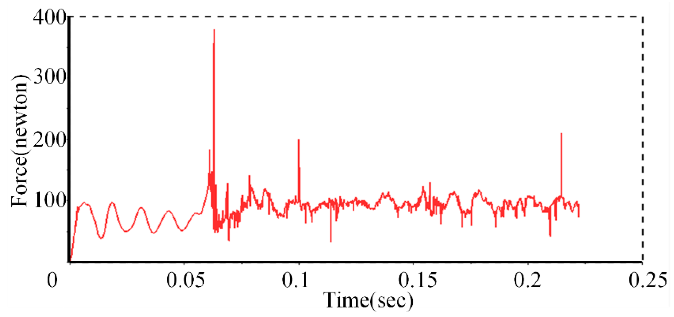
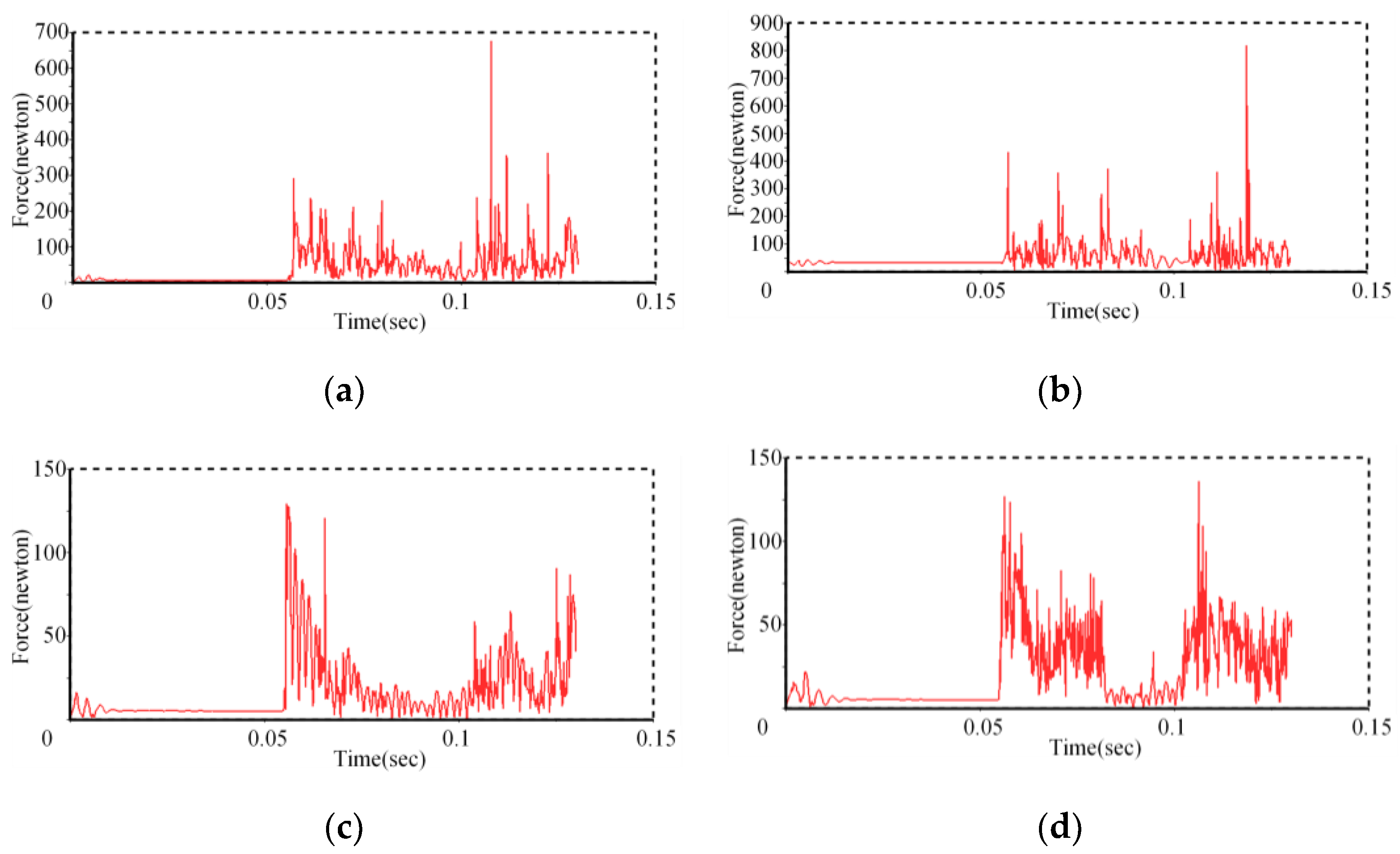
The force study of the leather cup in the actual cornering process is very complicated. Due to the unpredictable internal conditions of the pipeline, the pipeline robot may encounter particles, condensates, and sags at any time during the movement of the pipeline. Ideally, the cup will be subjected to not only the elastic force of the tube wall but also the force of the core tube and the device to fix the cup, as well as the driving force. From the previous static analysis results, we know that stress concentrations easily occur at the bolt hole. Through the introduction of flexible bodies to study the bending performance of the pipeline robot, we also found that the stress of the cup at the bolt hole is greater than that of other parts. The force at the bolt hole of the cup is mainly generated by the force between the cup and the core tube. The simulation conditions that conform to the current situation are selected to analyze the contact force between the cup and the core tube. The force between each cup and the core tube is shown in Figure 14a–d.
The contact force between each cup and the core tube remains basically unchanged, but when the pipe robot collides with the pipe, the force between the cup and the core tube will suddenly increase. The contact force generated after the collision is much greater than the contact force before the collision. At the same time, the maximum contact force between the second leather cup near the core tube and the core tube is the largest during movement, and the contact force between the two rear leather cups is very close. Therefore, during processing, the stability of the connection between the leather cup near the core tube and the core tube is strengthened, and the leather cup is thickened to prevent damage to the leather cup caused by excessive contact force.

4. Conclusions

In this paper, through experimental research, the two-cup PIG runs the fastest in the whole process, which has the smallest bending acceleration, and the contact force between the cup and the pipe wall is the largest when bending. The contact force between the cup and the pipe is minimal.
(1)
Through simulation research, the PIG speed of the two leather cups is the fastest in cornering, but the stress on the leather cups is too large, which can easily cause damage to the PIG leather cups. The speed of the leather cup PIG is very low when cornering, which affects its overall ability to pass through the pipe. When choosing the number of leather cups for the PIG to bend, one can give priority to four leather PIGs or six leather PIGs, which can improve the situation in which the PIGs block the pipeline due to wear of the leather cups.
(2)
When the leather cup interval ratio is 3%, the running speed is the fastest, but the PIG leather cup is easily damaged when the maximum stress reaches 9 MPa. The ratio of the leather cup interval to 10% of the PIG easily causes jamming when cornering, and the speed sharply decreases. Since the ratio of the leather cup interval to the length of the PIG is 7%, this setup is better than those of the other scenarios.
(3)
The increase in the number of cabins will seriously reduce the speed of the PIG movement, and the transmission of the force of the universal joint to the second half of the curve during cornering will also affect the entire PIG cornering speed. The force between the cross-universal joints is basically uniform during the whole movement process, and at some point, the force between the driving fork and the driven fork suddenly increases, which will cause the stress on the cup to increase. Additionally, the cup and pipe disengagement affect the movement of the entire PIG. When using the dual-cabin PIG for cornering, the damage to the leather cup can be decreased to a certain extent, the pressure difference between the front and rear is stable, and the service life of the leather cup is increased. However, the more important task is to solve the PIG power problem.
(4)
The contact force between each cup and the core tube remains basically unchanged during the bend, but when the pipeline robot collides with the pipeline, the contact force generated is much greater than the contact force before the collision. At the same time, the second cup closest to the core tube has the largest contact force with the core tube during movement. Therefore, during processing, strengthening the stability of the connection between the leather cup near the core tube and the core tube and thickening the leather cup to prevent damage to the leather cup caused by excessive contact force are considered.

Author Contributions

Conceptualization, S.C. and L.X.; methodology, S.C., L.X. and X.W.; software, L.X. and X.W.; validation, S.C., L.X. and X.W.; formal analysis, L.X., K.T., Y.Z. and M.Z.; investigation, L.X., K.T., Y.Z. and M.Z.; resources, S.C. and Y.G.; data curation, K.T., Y.Z. and M.Z.; writing—original draft preparation, S.C. and L.X.; writing—review and editing, S.C. and L.X.; visualization, S.C., L.X. and X.W.; supervision, S.C.; project administration, S.C.; funding acquisition, S.C. and Y.G. All authors have read and agreed to the published version of the manuscript.

Funding

This work was supported by the National Natural Science Foundation of China (U1908228).

Acknowledgments

The author contribution or funding sections have covered all support.

Conflicts of Interest

The authors declare that they have no known competing financial interests or personal relationships that could have appeared to influence the work reported in this paper.

References

  1. Sakakibara, N.; Kyriakides, S.; Corona, E. Collapse of partially corroded or worn pipe under external pressure. Int. J. Mech. Sci. 2008, 50, 1586–1597. [Google Scholar] [CrossRef]
  2. Zhang, C.; Rathnayaka, S.; Shannon, B.; Ji, J.; Kodikara, J. Numerical interpretation of pressurized corroded cast iron pipe tests. Int. J. Mech. Sci. 2017, 128–129, 116–124. [Google Scholar] [CrossRef] [Green Version]
  3. Liu, Y.; Cen, Z.; Chen, H.; Xu, B. Plastic collapse analysis of defective pipelines under multi-loading systems. Int. J. Mech. Sci. 2000, 42, 1607–1622. [Google Scholar] [CrossRef]
  4. Lu, H.; Iseley, T.; Behbahani, S.; Fu, L. Leakage detection techniques for oil and gas pipelines: State-of-the-art. Tunn. Undergr. Space Technol. 2020, 98, 103249. [Google Scholar] [CrossRef]
  5. Sina, R.; Raheleh, J.; Alexander, G. A review on different pipeline defect detection techniques. Flow Model. Control. Pipeline Syst. 2021, 321, 25–57. [Google Scholar]
  6. Ye, H.; Qian, J.; Yan, S.; Jiang, C.; Wei, L.; Jin, Z.-J. Limit bending moment for pipes with two circumferential flaws under combined internal pressure and bending. Int. J. Mech. Sci. 2016, 106, 319–330. [Google Scholar] [CrossRef]
  7. Azpiroz, J.E.; Hendrix, M.H.W.; Breugem, W.-P.; Henkes, R.A.W.M. CFD Modelling of Bypass Pigs with a Deflector Disk. In Proceedings of the 17th International Conference on Multiphase Production Technology, Cannes, France, 10–12 June 2015; pp. 141–158. [Google Scholar]
  8. Kohda, K.; Suzukawa, Y.; Furukawa, H. New method for analyzing transient flow after pigging scores well. Oil Gas J. 1988, 86, 40–47. [Google Scholar]
  9. Kohda, K.; Suzukawa, Y.; Furukawa, H. Pigging analysis for gas-liquid two phase flow in pipelines. In Proceedings of the ASME Annual Energy Resources Technology Conference and Exhibition, New Orleans, LA, USA; 1988; pp. 33–38. [Google Scholar]
  10. Wang, L.; Bi, H.; Yang, Y.; Zhang, Y.; Li, Y. Response analysis of an aerial-crossing gas-transmission pipeline during pigging operations. Int. J. Press. Vessel. Pip. 2018, 165, 286–294. [Google Scholar] [CrossRef]
  11. Wang, L.; Yang, Y.; Liu, C.; Li, Y.; Hu, Q. Numerical investigation of dynamic response of a pipeline-riser system caused by severe slugging flow. Int. J. Press. Vessel. Pip. 2018, 159, 15–27. [Google Scholar] [CrossRef]
  12. Wang, L.; Yang, Y.; Li, Y.; Wang, Y. Dynamic behaviours of horizontal gas-liquid pipes subjected to hydrodynamic slug flow: Modelling and experiments. Int. J. Press. Vessel. Pip. 2018, 161, 50–57. [Google Scholar] [CrossRef]
  13. Xinyu, Z.; Bo, Z.; Yuanzhang, J.; Bo, L.; Rui, L.; Lin, Z.; Qiao, S.; Xiaoli, Z. Analysis of Rotation of Pigs during Pigging in Gas Pipeline. In Proceedings of the 2015 International Conference on Fluid Power and Mechatronics (FPM), Harbin, China, 5–7 August 2015; pp. 892–895. [Google Scholar]
  14. Aksenov, D.V.; Shcherbakov, V.I.; Leshchenko, V.V. Selection of structural parameters of an inspection pig for arterial oil and gas pipelines from conditions of dynamics. Chem. Pet. Eng. 2013, 49, 265–269. [Google Scholar] [CrossRef]
  15. Shcherbakov, V.I.; Aksenov, D.V. Selecting the mechanical parameters of an inspection device for oil and gas lines. Russ. Eng. Res. 2013, 33, 679–682. [Google Scholar] [CrossRef]
  16. Aksenov, D.V.; Shcherbakov, V.I.; Leshchenko, V.V. Self-oscillation of flaw-detection equipment for arterial gas pipelines. Chem. Pet. Eng. 2012, 48, 364–371. [Google Scholar] [CrossRef]
  17. Saeidbakhsh, M.; Rafeeyan, M.; Ziaei-Rad, S. Dynamic Analysis of Small Pigs in Space Pipelines. Oil Gas Sci. Technol. 2008, 64, 155–164. [Google Scholar] [CrossRef]
  18. Lesani, M.; Rafeeyan, M.; Sohankar, A. Dynamic analysis of small pig through two and three-dimensional liquid pipeline. J. Appl. Fluid Mech. (JAFM) 2012, 5, 75–83. [Google Scholar]
  19. Quarini, J.; Shire, S. A review of fluid-driven pipeline pigs and their applications. Proc. Inst. Mech. Eng. Part E 2007, 221, 1–10. [Google Scholar] [CrossRef]
  20. Dongyuan, S.; Yang, X.; Wasim, H.; Hongxi, R.; Xiaoyan, T. Fluid-Solid Coupling Numerical Analysis of Dynamic Vibration Characteristics of the Pipeline Inspection Gauge (PIG) in the Pipeline. In Proceedings of the INTER-NOISE and NOISE-CON Congress and Conference Proceedings, Hong Kong, China, 27–30 August 2017; pp. 261–269. [Google Scholar]
  21. Hongxi, R.; Dongyuan, S.; Yang, X.; Hongchao, W. Research on Dynamics and Vibration Response in Pipeline Inspection Gauge (PIG) Based on the CEL Method. In Proceedings of the INTER-NOISE and NOISE-CON Congress and Conference Proceedings, Hong Kong, China; 2017; pp. 56–67. [Google Scholar]
  22. Cao, Y.; Liu, C.; Tian, H.; Sun, Y.; Zhang, S. Mechanical behaviors of pipeline inspection gauge (pig) in launching process based on Coupled Eulerian-Lagrangian (CEL) method. Int. J. Press. Vessel. Pip. 2022, 197, 104622. [Google Scholar] [CrossRef]
  23. Cao, Y.; Chang, Q.; Zhen, Y. Numerical simulation of fracture behavior for the pipeline with girth weld under axial load. Eng. Fail. Anal. 2022, 136, 106221. [Google Scholar] [CrossRef]
  24. Azevedo, L.; Bracm, A.; Nieckele, A.; Naccxhe, M.; Gomes, M. Simple HydrodynamicModels for the Prediction of Pig Motions in Pipelines. In Proceedings of the Offshore Technology Conference, Houston, TX, USA, 6 May 1996; pp. 729–739. [Google Scholar] [CrossRef]
  25. Nieckele, A.O.; Braga, A.M.B.; Azevedo, L.F.A. Transient Pig Motion Through Gas and Liquid Pipelines. J. Energy Resour. Technol. 2001, 123, 260–269. [Google Scholar] [CrossRef]
  26. Azevedo, L.; Braga, A.; Nieckele, A.; Souza Mendes, P. Simulating pipeline pigging operations. In Proceedings of the Pipeline Pigging Conference, Stavanger, Norway, 15 June 1999; pp. 15–17. [Google Scholar]
  27. Solghar, A.A.; Davoudian, M. Analysis of Transient PIG Motion in Natural Gas Pipeline. Mech. Ind. 2012, 13, 293–300. [Google Scholar] [CrossRef]
  28. Esmaeilzadeh, F.; Mowla, D.; Asemani, M. Mathematical modeling and simulation of pigging operation in gas and liquid pipelines. J. Pet. Sci. Eng. 2009, 69, 100–106. [Google Scholar] [CrossRef]
  29. Esmaeilzadeh, F.; Asemani, M.; Mowla, D. Modeling of Pig Operations in Natural Gas and Liquid Pipeline. In Proceedings of the SPE Annual Technical Conference and Exhibition, San Antonio, TX, USA, 24 September 2006; pp. 1–4. [Google Scholar] [CrossRef]
  30. Ayala, L.F.; Eltohami, E.S.; Adewumi, M.A. A Unified Two-Fluid Model for Multiphase Flow in Natural Gas Pipelines. In Proceedings of the Engineering Technology Conference on Energy, Houston, TX, USA, 4–5 February 2002; pp. 839–845. [Google Scholar] [CrossRef]
  31. Ayala, L.F.; Adewumi, M.A. Low-Liquid Loading Multiphase Flow in Natural Gas Pipelines. J. Energy Resour. Technol. 2003, 125, 284–293. [Google Scholar] [CrossRef]
  32. Ayala, O.; Ayala, L.; Ayala, O. Multi-phase Flow Analysis in Oil and Gas Engineering Systems and its Modelling. Hydrocarb. World 2007, 2007, 57–60. [Google Scholar]
  33. Durali, M.; Fazeli, A.; Nabi, A. Investigation of Dynamics and Vibration of PIG in Oil and Gas Pipelines. In Proceedings of the ASME International Mechanical Engineering Congress and Exposition, Seattle, DC, USA, 11–15 November 2007; pp. 2015–2024. [Google Scholar] [CrossRef]
  34. Zhang, H.; Zhang, S.; Guo, S.; Mingjun, O.U.; Lin, L. Dynamics Simulation on Bi-directional PIG’Sealing Dish Passing through Girth Weld in Pipeline. Oil Field Equip. 2015, 44, 22–27. [Google Scholar] [CrossRef]
  35. Zhang, H.; Qing, L.I.; Liu, S.; Mingjun, O.U.; Lin, L. Effect on Stiffness Characteristics of Large Bi-directional PIG’s Rubber Sealing Disc by Its Thickness. Oil Field Equip. 2015, 44, 12–18. [Google Scholar]
  36. Xiang, J.; Morgenstern, H.; Li, Y.; Steffick, D.; Bragg-Gresham, J.; Panapasa, S.; Raphael, K.L.; Robinson, B.M.; Herman, W.H.; Saran, R. Incidence of ESKD Among Native Hawaiians and Pacific Islanders Living in the 50 US States and Pacific Island Territories. Am. J. Kidney Dis. 2020, 76, 340–349.e1. [Google Scholar] [CrossRef]
  37. Zhang, X.; Liu, S.; Qing, L.I.; Zhang, S. Effect of Interference of Leather Sealing Disc to Stiffness of PIG. Process Equip. Piping 2015, 52, 82–86. [Google Scholar]
  38. He, H.; Liang, Z.; Cui, X. Molding and Simulation of Pig Speed with Brake Unit in Gas Pipeline. J. Pipeline Syst. Eng. Pract. 2020, 11, 04019042. [Google Scholar] [CrossRef]
  39. Liang, Z.; He, H.; Cai, W. Speed simulation of bypass hole PIG with a brake unit in liquid pipe. J. Nat. Gas Sci. Eng. 2017, 42, 40–47. [Google Scholar] [CrossRef]
  40. Zhu, X.; Zhang, S.; Wang, D.; Wang, W.; Liu, S. The impact of pipeline bend on bi-directional pig and the theories for the optimal pig design. In Proceedings of the 2013 IEEE International Conference on Mechatronics and Automation, Takamatsu, Japan, 4–7 August 2013; pp. 87–92. [Google Scholar]
  41. Wang, W.; Song, S.; Zhang, S.; Yu, D. Impact analysis of pigging in shield segment of gas pipe. In Proceedings of the 2012 IEEE International Conference on Mechatronics and Automation, Chengdu, China, 5–8 August 2012; pp. 203–207. [Google Scholar] [CrossRef]
  42. Deng, T.; Zhou, J.; Liang, G.; Xiao, Y.; Zhu, B.; Gong, J. Numerical Simulation of Pigging Operation through Curved Pipeline Coupling a T-Abrupt and Bend Drain Pipe. J. Pipeline Syst. Eng. Pract. 2021, 12, 04020052. [Google Scholar] [CrossRef]
  43. Deng, T.; Zhou, J.; Zhou, X.; Meng, T.; Liang, G.; Gong, J. Transient simulation of vapor-liquid eruption and overpressure in the drainage terminal of an inclined pipeline during pigging process after water pressure test. Water Supply 2020, 21, 204–216. [Google Scholar] [CrossRef]
  44. Liu, C.; Wei, Y.; Cao, Y.; Zhang, S.; Sun, Y. Traveling ability of pipeline inspection gauge (PIG) in elbow under different friction coefficients by 3D FEM. J. Nat. Gas Sci. Eng. 2020, 75, 103134. [Google Scholar] [CrossRef]
  45. Liu, C.; Cao, Y.; Jinzhong, C.; Renyang, H.; Xin, J.; Wu, S. Research on Mechanical Behaviors of Submarine Pipeline Inspection Gauges in the Elbow: Fsi Simulation and Mathematic Modeling. 2022, pp. 1–28. Available online: https://papers.ssrn.com/sol3/papers.cfm?abstract_id=4186661 (accessed on 18 October 2022).
  46. Liu, C.; Yuguang, C.; Jinzhong, C.; Chaolei, D.; Renyang, H.; Zhenggan, Z. The Blockage Risk in the Elbow of the Bi-Directional Pig Used for Submarine Pipeline Based on the Modified Burgers-Frenkel (Mb-F) Model. 2022, pp. 1–29. Available online: https://papers.ssrn.com/sol3/papers.cfm?abstract_id=4170957 (accessed on 18 October 2022).
  47. Zhu, X.; Wang, D.; Yeung, H.; Zhang, S.; Liu, S. Comparison of linear and nonlinear simulations of bidirectional pig contact forces in gas pipelines. J. Nat. Gas Sci. Eng. 2015, 27, 151–157. [Google Scholar] [CrossRef]
  48. Zhu, X.; Zhang, S.; Li, X.; Wang, D.; Yu, D. Numerical simulation of contact force on bi-directional pig in gas pipeline: At the early stage of pigging. J. Nat. Gas Sci. Eng. 2015, 23, 127–138. [Google Scholar] [CrossRef]
  49. Zhu, X.; Wang, W.; Zhang, S.; Liu, S. Experimental Research on the Frictional Resistance of Fluid-Driven Pipeline Robot with Small Size in Gas Pipeline. Tribol. Lett. 2017, 65, 49. [Google Scholar] [CrossRef]
  50. Canavese, G.; Scaltrito, L.; Ferrero, S.; Pirri, C.; Cocuzza, M.; Pirola, M.; Corbellini, S.; Ghione, G.; Ramella, C.; Verga, F.; et al. A novel smart caliper foam pig for low-cost pipeline inspection—Part A: Design and laboratory characterization. J. Pet. Sci. Eng. 2015, 127, 311–317. [Google Scholar] [CrossRef]
  51. Ramella, C.; Canavese, G.; Corbellini, S.; Pirola, M.; Cocuzza, M.; Scaltrito, L.; Ferrero, S.; Pirri, C.; Ghione, G.; Rocca, V.; et al. A novel smart caliper foam pig for low-cost pipeline inspection–Part B: Field test and data processing. J. Pet. Sci. Eng. 2014, 133, 771–775. [Google Scholar] [CrossRef]
  52. Nguyen, T.T.; Kim, D.K.; Rho, Y.W.; Kim, S.B. Dynamic modeling and its analysis for PIG flow through curved section in natural gas pipeline. In Proceedings of the Proceedings 2001 IEEE International Symposium on Computational Intelligence in Robotics and Automation (Cat. No. 01EX515), Banff, AB, Canada, 29 July–1 August 2001; pp. 492–497. [Google Scholar] [CrossRef]
  53. Nguyen, T.T.; Yoo, H.R.; Rho, Y.W.; Kim, S.B. Speed control of PIG using bypass flow in natural gas pipeline. In Proceedings of the ISIE 2001. 2001 IEEE International Symposium on Industrial Electronics Proceedings (Cat. No. 01TH8570), Pusan, Korea, 12–16 June 2001; pp. 863–868. [Google Scholar] [CrossRef]
  54. Hendrix, M. Experiments and Modelling for By-Pass Pigging of Pipelines. Ph.D. Thesis, Delft University of Technology, Delft, The Netherlands, 2020; pp. 2–6. [Google Scholar] [CrossRef]
  55. Yang, L.; Fu, H.; Liang, H.; Wang, Y.; Han, G.; Ling, K. Detection of pipeline blockage using lab experiment and computational fluid dynamic simulation. J. Pet. Sci. Eng. 2019, 183, 106421. [Google Scholar] [CrossRef]
  56. Fu, H.; Yang, L.; Liang, H.; Wang, S.; Ling, K. Diagnosis of the single leakage in the fluid pipeline through experimental study and CFD simulation. J. Pet. Sci. Eng. 2020, 193, 107437. [Google Scholar] [CrossRef]
  57. Mishra, D.; Agrawal, K.K.; Abbas, A.; Srivastava, R.; Yadav, R.S. PIG [Pipe Inspection Gauge]: An Artificial Dustman for Cross Country Pipelines. Procedia Comput. Sci. 2019, 152, 333–340. [Google Scholar] [CrossRef]
  58. Feng, C.L.; Wang, D.S.; Zhu, Y.Y. Analysis of Moment Transmitted by Universal Joint in Varying Operating Condition. Adv. Eng. Forum 2011, 2–3, 999–1003. [Google Scholar] [CrossRef] [Green Version]
  59. Feng, C.L.; Zhu, Y.Y.; Wang, D.S. Super-Harmonic Resonance Analysis on Torsional Vibration of Misaligned Rotor Driven by Universal Joint. Appl. Mech. Mater. 2010, 26–28, 1226–1231. [Google Scholar] [CrossRef]
Figure 1. Movement model.
Machines 10 00963 g001
Figure 2. Serving system and observation areas A, B, C, D: (a) 1, 2 and 3 are ball value 1, 2 and 3; (b) A, B, C and D are the four observation areas.
Machines 10 00963 g002
Figure 3. Pipeline robot with 2, 4, and 6 bowls.
Machines 10 00963 g003
Figure 4. Pressure sensor values for each monitoring section: (a) A observation area; (b) B observation area; (c) C observation area; (d) D observation area.
Machines 10 00963 g004
Figure 5. Velocity at each node, average acceleration, and resistance during cornering: (a) change of speed; (b) change of acceleration.
Machines 10 00963 g005
Figure 6. Comparison of the speed of different cup numbers of pipe cleaners through bends: (a) number of cups is 2, (b) number of cups is 3, (c) number of cups is 4, (d) number of cups is 6, (e) and number of cups is 8.
Machines 10 00963 g006
Figure 7. Stress cloud diagram for 4 and 2 cups.
Machines 10 00963 g007
Figure 8. Maximum stress versus speed for different cup pipe robots during bending.
Machines 10 00963 g008
Figure 9. Movement speed of different cup interval ratios: (a) cup spacing ratio of 3%; (b) cup spacing ratio of 10%; (c) cup spacing ratio of 7%; and (d) cup spacing ratio of 8%.
Machines 10 00963 g009
Figure 10. Comparison of the maximum stress of different cup spacing ratios.
Machines 10 00963 g010
Figure 11. Bending speed of the double-segment pipeline robot and single-segment pipeline robot.
Machines 10 00963 g011
Figure 12. Force between the cross-universal joint active shaft fork and driven shaft fork.
Machines 10 00963 g012
Figure 13. Comparison of the maximum stress of each numbered leather cup and the contact force of the previous numbered leather cup.
Machines 10 00963 g013
Figure 14. Contact forces between the cup bowl and the core tube.
Machines 10 00963 g014
Table 1. Piping laboratory equipment.
PartsMaterial/ModelNumber
Straight pipesAcrylic glass/stainless steel4
BendsAcrylic glass/stainless steel4
Pipe fixing clipsStainless steel8
Pressure control pumpsCDMF10-8FSWSC1
Pressure sensorsMIK-P30013
Flow metersCaliber DN251
Flow control valvesCaliber DN501
Table 2. Pipeline robot components.
PartsMaterialDimensions (mm)
FlangesAluminum10
MandrelAluminum60
Leather bowlsPolyurethane25
End capsAluminum10
Publisher’s Note: MDPI stays neutral with regard to jurisdictional claims in published maps and institutional affiliations.