Article

The Effect of Manufacturing Errors on the Performance of a Gas-Dynamic Bearing Gyroscope

Research Center of Fluid Machinery Engineering and Technology, Jiangsu University, Zhenjiang 212013, China
*
Author to whom correspondence should be addressed.
Machines 2022, 10(11), 1010; https://doi.org/10.3390/machines10111010
Submission received: 5 October 2022 / Revised: 28 October 2022 / Accepted: 29 October 2022 / Published: 1 November 2022
(This article belongs to the Section Advanced Manufacturing)

Abstract

:
The purpose of this paper is to investigate the effect of manufacturing errors on the performance of a gas-dynamic bearing gyroscope. Five kinds of manufacturing errors including bearing taper error, oval error, trigone error, eccentricity of the axis, and angular deviation of the axis are studied. A mathematic model of these errors is established to describe the variation of gas film thickness. The Reynolds equation is solved, and the perturbation method is applied to analyze the performance of the gas-dynamic bearing with the manufacturing errors. Based on the analysis, the interference torque and overload limit are investigated to assess the effects of manufacturing errors. Results show that taper error will cause interference torque. Oval error or trigone error will cause interference torque with a radial specific force. The eccentricity or angular deviation of the axis will cause interference torque with any specific force. In general, the interference torque is small, which is 10–1000 times smaller than that under the condition of both radial and axial specific forces. The manufacturing errors also reduce the ultimate overload significantly. The taper error has the greatest influence on the gas-dynamic bearing gyroscope among the manufacturing errors studied in this paper.

1. Introduction

Gas-dynamic bearing gyroscopes are mainly used in ultraprecise inertial navigation systems. In order to improve the sensitivity, they use gas-dynamic bearings to support the rotor, whose rotating speed is up to 0.1 million rotations per minute or faster [1]. As the clearance of gas-dynamic bearing is very thin, which is usually 2 μm or thinner, the performance is sensitive to manufacturing errors [2]. As a result, the machining and assembling precision is ultrahigh. It is important to investigate the effect of manufacturing errors, which could provide theoretical guidance for gyroscope design.
Many works have studied the performance of gas-dynamic bearings. Nielson [3,4] designed a gas-dynamic foil journal bearing and led a numerical study on the steady state and transient behavior. Liu [5] analyzed the stability of herringbone grooved journal gas bearings with two-dimensional narrow theory. Zhang [6] investigated the dynamic behavior of a gas journal bearing for microengine, considering the effects of temperature. Bailey [7] designed a small gap gas lubricated bearing and calculated the minimum clearance for various design with Navier slip boundary conditions. Tkacz [8] established a numerical model of the dynamic behavior of a self-acting gas journal bearing. Du [9] analyzed the nonlinear dynamic characteristics of a spiral grooved opposed-hemisphere gas bearing with the assumption of rigid rotor. Pronobis [10] compared the results of stability limits obtained by time integration and perturbation approach for a gas-dynamic bearing. Feng [11,12] designed a spherical spiral groove gas bearing and analyzed the effect of slip flow and roughness on the dynamic characteristics. Li [13,14] led a numerical investigation on the interference torque of a gas-dynamic bearing gyroscope and established an error model to predict the error caused by specific force and the flexibility of the gas-dynamic bearing.
Few researchers have paid attention to the effect of manufacturing errors of a gas-dynamic bearing gyroscope. Hu [2] studied the effect of taper error on the performance of gas foil conical bearing. He analyzed the static and dynamic performance under different taper errors by solving the Reynolds equation and the film thickness equation, and he found that the taper error decreases the direct stiffness and cross-coupled damping, with the bearing stability weakened. Guenat [15] proposed a tolerance method to optimize the grooved gas journal bearings for robustness in manufacturing tolerances. Liu [16] analyzed the correlation between the vortex torque and several kinds of manufacturing errors, including the oval error, three-lobing error and slot disalignment. Liang [17] studied the influence of surface roughness on the vortex torque of a gas-floated gyroscope. Yang [18] investigated the effect of the out-of-sphericity and assembly error on the gas-dynamic bearing, considering the bearing load, dynamic characteristics and friction torque. Li [19] studied the influence of the elliptical error on the performance of porous aerostatic bearings. Ren [20] investigated the influence of machining errors of hydrodynamic gas bearing on the stiffness. The aforementioned studies only considered the interference torque or bearing load, while the manufacturing errors could also reduce the overload limit of the gyroscope. In addition, few error types were studied, and no comparison was made. At present, the effect of manufacturing errors has not been studied comprehensively.
This paper investigates the effect of common manufacturing errors, including bearing taper error, oval error, trigone error, eccentricity of the axis, and angular deviation of the axis. Mathematic models are established to describe the gas film thickness considering the errors. The load capacity of the gas-dynamic bearings with the errors is calculated by solving the Reynolds equation. The interference torque and overload limit are analyzed to assess the effects of the manufacturing errors.

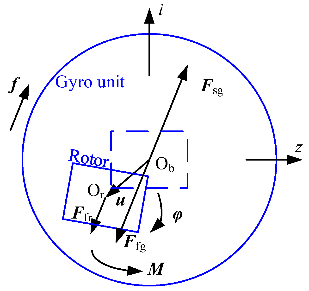
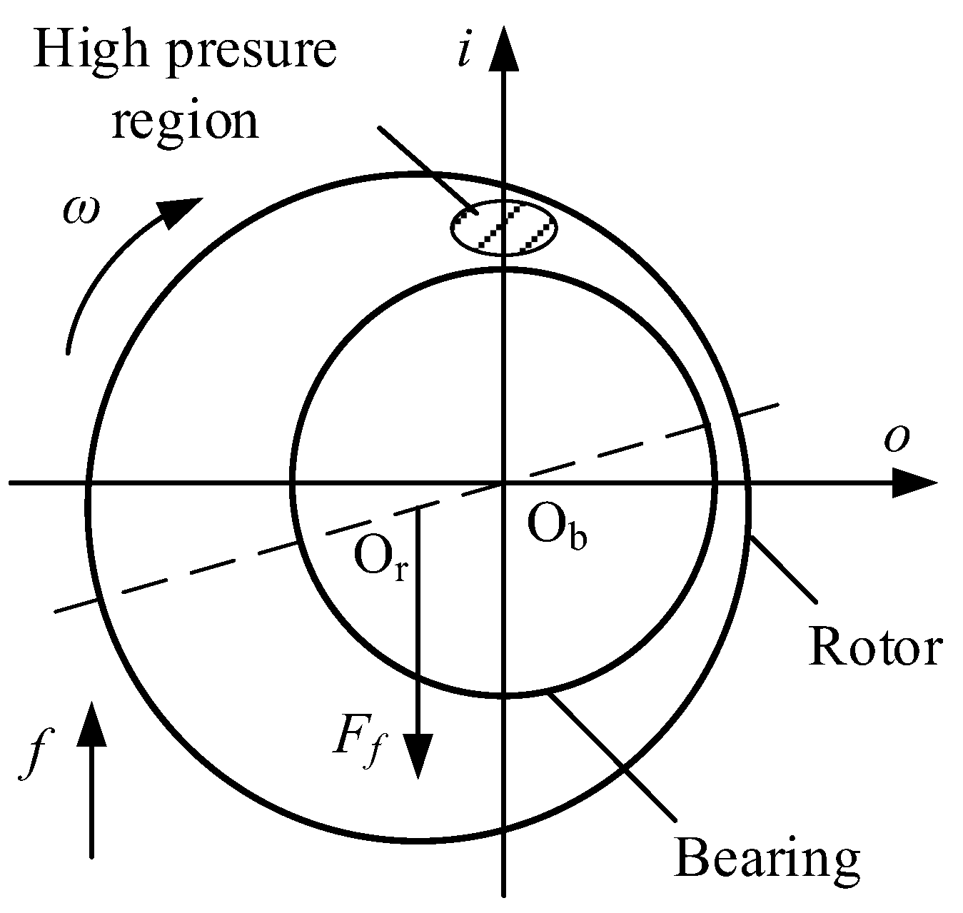
2. Mechanical Model of the Gyroscope

Figure 1 shows the schematic structure of the gas-dynamic bearing gyroscope. The gyro rotor is supported by the gas film in the clearance between the gyro rotor and bearing, and it rotates around the spin axis (s-axis). The bearing is fixed inside the gyro unit, which could only rotate around the output axis (o-axis). When the carrier rotates around the input axis (i-axis), a gyroscopic moment around the o-axis is produced on the gyro unit, which affects the feedback control system composed of the angular displacement sensor and the torque converter. The current in the system is detected to estimate the angular velocity of the carrier.
The configuration of the gas-dynamic bearing is shown in Figure 2, the rotating speed of the rotor is ω, the mass of the rotor is m. The bearing consists of two opposite cones with taper kt, bottom radius R and width b, which is connected by a shaft whose length is d. Grooves are carved on the bearing surface in a spiral manner with the groove angle βg and the groove depth hg. The clearance between the rotor and the bearing is c.

3. Mathematical Model of the Manufacturing Errors

3.1. Taper Error

The bearing clearance is formed between the outer cone surface of the rotor and the inner cone surface of the bearing. If the taper of the two cone surfaces is not equal, the gas film in the clearance will be wedge-shaped, which could cause the uneven distribution of gas flow along the axial direction. As shown in Figure 3, it is assumed that the taper of one cone surface of bearing has an error of Δkt, with the radius of the median plane unchanged. The film thickness could be expressed as the sum of the theoretical thickness [21] and the variation caused by the taper error; thus,
h = c + ( u + φ × x ) n ξ + h g + h e ξ ξ = 1 , 2
h e 1 = ( b s d b / 2 ) Δ k t / 1 + k t 2 ,   h e 2 = 0
where h is the thickness of the gas film, u is the rotor eccentric displacement, φ is the tilting angle of the rotor, x = (i, o, s) is the coordinate in the reference frame Obios, nξ is the normal unit vector of the bearing surface, heξ is the variation caused by manufacturing error, and ξ is the index of the cone surfaces, with ξ = 1 for the cone in the positive s-axis and ξ = 2 for the cone in the negative s-axis.

3.2. Oval Error and Trigone Error

The clamping mode and the stress during machining the cone surface may cause the oval error and the trigone error, which will cause the uneven distribution of the gas film in the circumferential direction. If the errors or installation angles on both sides are different, interference torque may be produced under the action of radial specific force. Figure 4 shows the schematic of oval error and trigone error of the bearing. It is assumed that the cross-section with an oval error is an ellipse whose major axis is ep2 longer than the minor axis, the same as trigone error ep3, and the difference of the phase angle between the two sides is θp. So, the variation of film thickness with the oval error is expressed as follows
h e 1 = e p 2 2 cos ( 2 θ ) ,   h e 2 = e p 2 2 cos [ 2 ( θ θ p ) ]
The variation of film thickness with the trigone error is expressed by
h e 1 = e p 3 2 cos ( 3 θ ) ,   h e 2 = e p 3 2 cos [ 3 ( θ θ p ) ]

3.3. Eccentricity of the Axis

The axis eccentricity of bearing installation could cause an extra bearing force and bearing moment even if the rotor is in the theoretical balance position. It results in an eccentric motion and tilting motion of the rotor even without any specific force or angular velocity of the carrier. Therefore, specific force in any direction could cause an interference torque. As shown in Figure 5, the eccentricity of the axis of the cone in the positive s-axis is assumed to be eeb with the attitude angle θeb. It is equivalent to an extra displacement of the rotor −eebv = (−eebcosθeb, −eebsinθeb, 0) when calculating the film thickness in the positive s-axis. So, the gas film thickness distribution is expressed by
h = { c + ( u e ebv + φ × x ) n ξ + h g , ξ = 1 c + ( u + φ × x ) n ξ + h g , ξ = 2
The variation of film thickness with the eccentricity of the axis is obtained as follows
h e 1 = e ebv n ξ = e eb cos θ eb cos θ / 1 + k t 2 e eb sin θ eb sin θ / 1 + k t 2

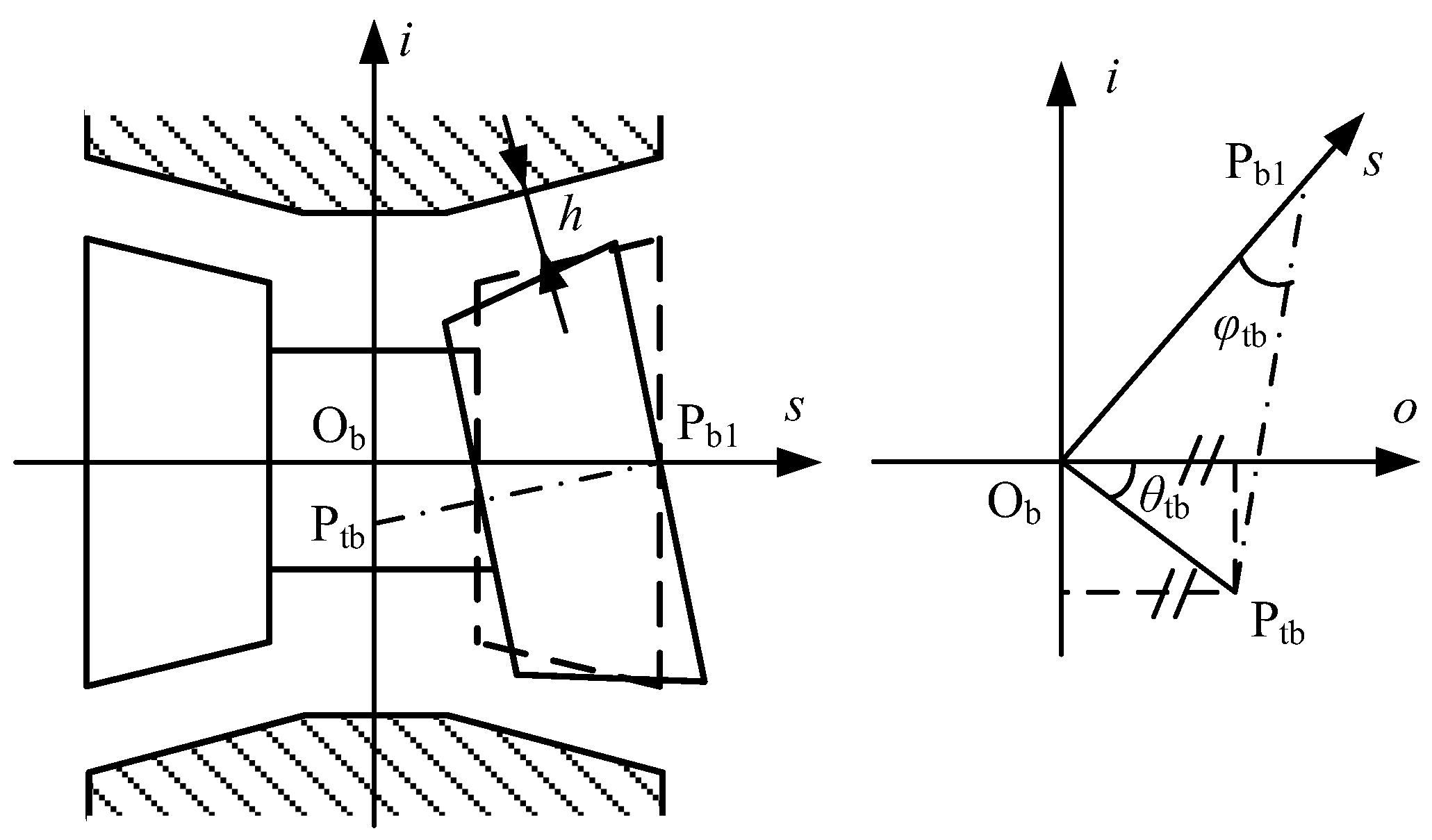
3.4. Angular Deviation of the Axis

The angular deviation of the axis may be caused by the machining error of the bearing end face and the inner wall surface of the gyro unit or in the assembly process. As shown in Figure 6, we assume that the cone in the positive s-axis inclines around the center Pb1 of its end face, and the inclination angle is −φtb. The intersection point between the tilted axis and the io plane is Ptb, and the angle between the straight line ObPtb and i-axis is θtb. It could be considered that the inclined bearing has an attitude angle φtbv = (φtbcosθtb, φtbsinθtb, 0). When calculating the film thickness in the positive s-axis, the rotor could be regarded as turning φtbv around Pb1 relative to the bearing. So, the gas film thickness is expressed as follows
h = { c + [ u + φ tbv × x b 1 + ( φ φ tbv ) × x ] n ξ + h g , ξ = 1 c + ( u + φ × x ) n ξ + h g , ξ = 2
The variation of film thickness with the angular deviation of the axis is obtained as follows
h e 1 = ( φ tbv × x b 1 φ tbv × x ) n ξ
Thus,
h e 1 = φ tb 1 + k t 2 ( b Z b + k t R + k t 2 b Z k t 2 b ) sin ( θ tb θ )

4. Method to Estimate the Effect

To estimate the effect of the manufacturing errors, the corresponding variations of gas film expressed by Equations (2)–(4), (6) and (9) are plugged into the following Reynolds equation [22]
Z ( p Q h 3 p Z ) + 1 ( R + k b Z k b ) 2 θ ( p Q h 3 p θ ) = 6 μ ω ( p h ) θ
where p is the pressure of the gas film, Q is the Poiseuille flow rate coefficient in the Fukui–Kaneko model, and μ is the viscosity of the gas.
The Reynolds equation is solved by the numerical method proposed in the previous study [22] with bearing force and bearing torque obtained. The corresponding perturbed Reynolds equations and the numerical method proposed in the previous study [23] are also applied to obtain the stiffness matrix K. Based on the methods mentioned above, the interference torque and overload limit are investigated.

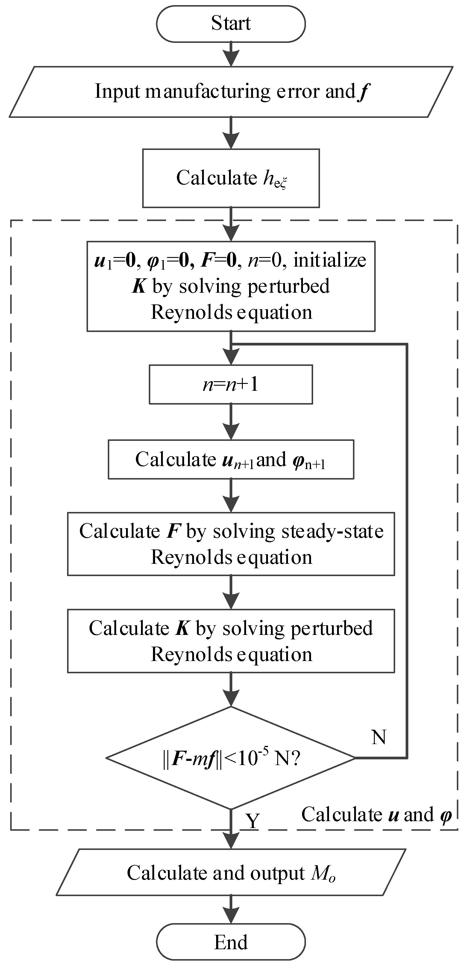
4.1. Interference Torque
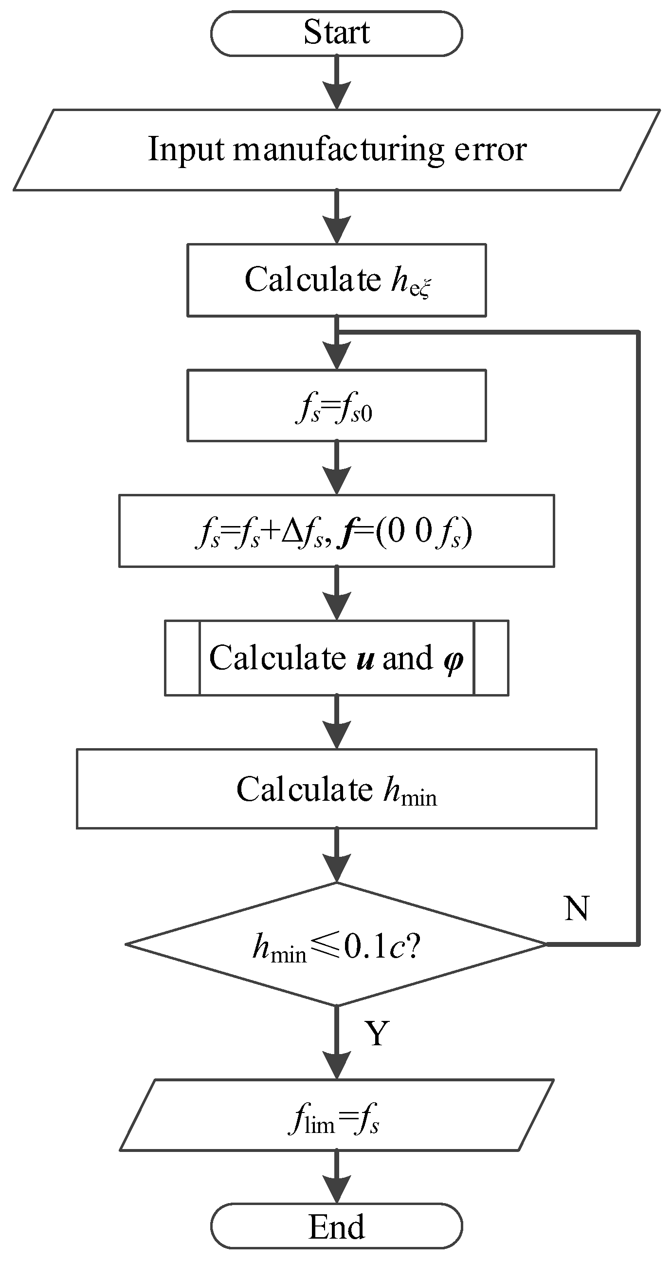
As the dimension of the clearance is much smaller than the bearing, even a small manufacturing error will have a great impact on the thickness of gas film. As a result, the performance of the gas-dynamic bearing and the precision of the gyroscope are both sensitive to manufacturing errors. The interference torque is investigated to estimate the influence. As shown in Figure 7, when the carrier moves with specific force f, which is defined by the acceleration of the carrier minus the acceleration of gravity, the gyro unit is supported with force Fsg, and its apparent gravity is Ffg. The rotor has an eccentric displacement u and tilting angle φ as a result of the specific force and the manuscript error, and its apparent gravity is Ffr. So, the gyro unit is out of balance with the following interference torque.
M o = u × F e o
Figure 8 shows the program flow chart for calculating interference torque. Firstly, the variation of film thickness heξ is calculated according to the manufacturing error; then, the rotor displacement u is solved by the specific force f by using the perturbation method and iterative method, and finally, the interference torque Mo is calculated.

4.2. Overload limit

Manufacturing errors also affect the carrying capacity of the gas-dynamic bearing, and as a result, the overload limit of the gyroscope may be lower. Specific force beyond the overload limit may cause direct contact between the rotor and bearing, and even a short period of dry friction may lead to serious failure of the gyroscope. Therefore, the relationship between overload limit and manufacturing errors is investigated. Figure 9 shows the program flow chart for calculating the overload limit. Firstly, the variation of film thickness caused by manufacturing error is calculated. Then, the initial specific force fs0 along the s-axis is given, and the corresponding rotor displacement u and minimum film thickness hmin are calculated until hmin is less than 0.1c. Finally, the corresponding specific force fs is taken as the ultimate overload flim.

5. Results and Discussion

Based on the aforementioned theories, a computer program is developed with the parameters shown in Table 1.

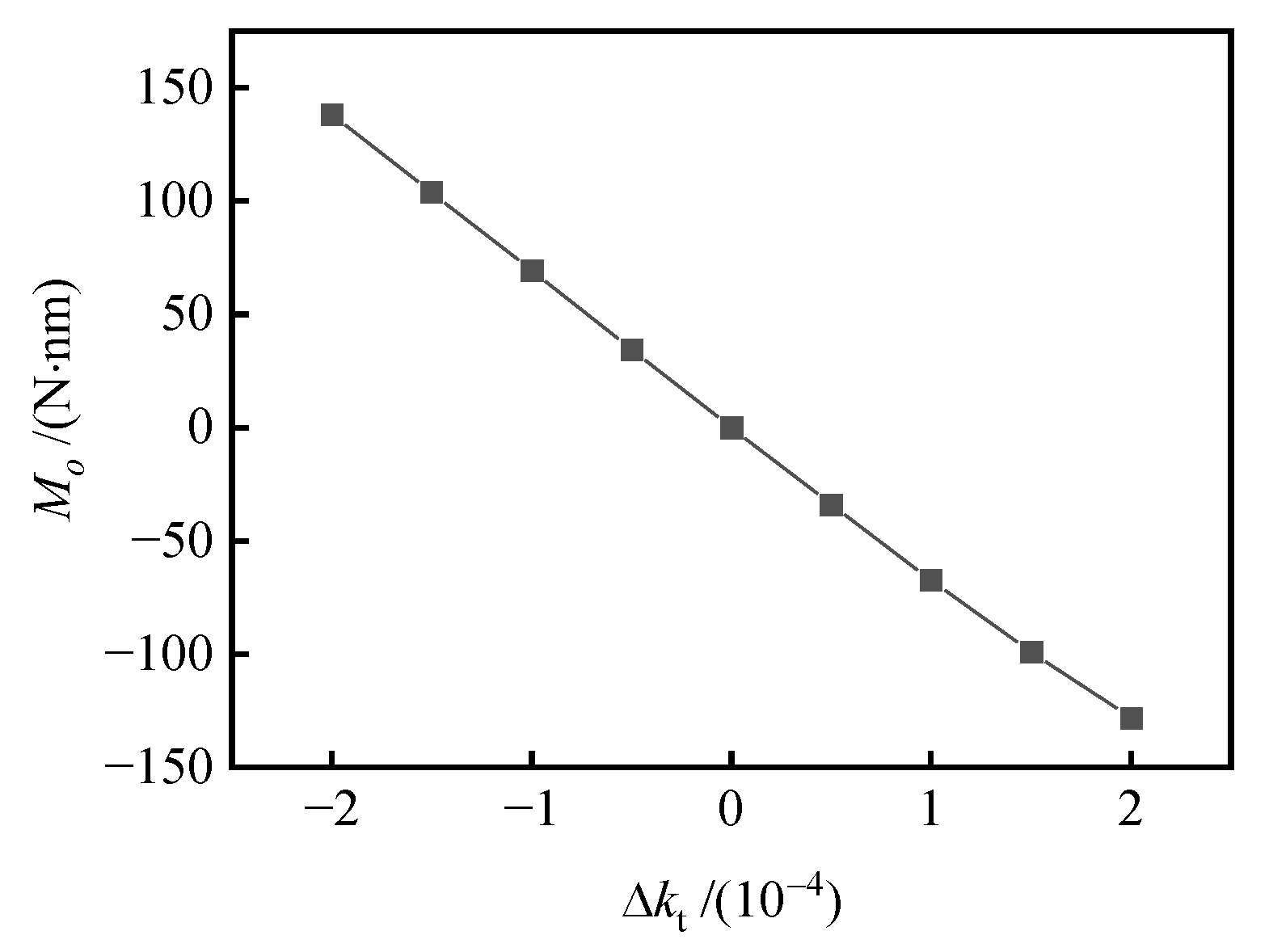
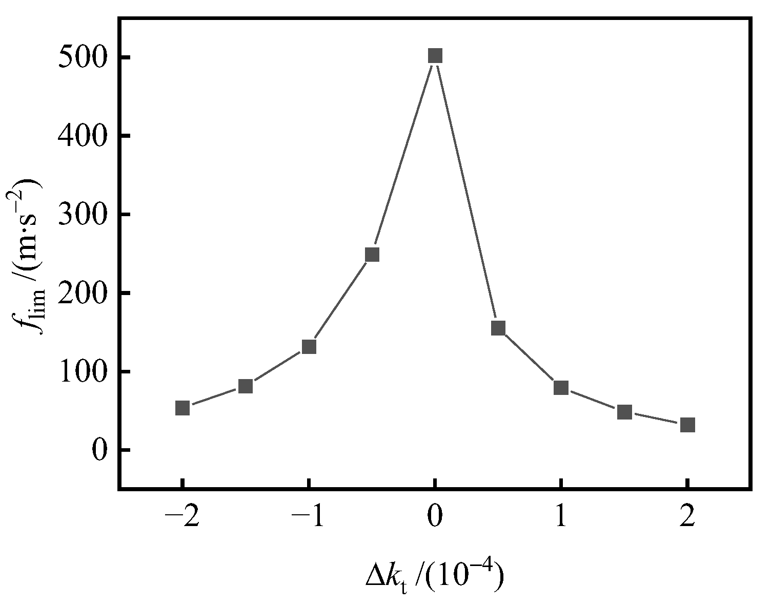
5.1. Effects of Taper Error

The taper error on one side of the bearing may break the symmetry of the system. Even only radial specific force could produce axial rotor displacement, which results in the interference torque. Figure 10 presents the interference torque caused by a variety of taper errors. When the bearing taper is too large, it will produce negative interference torque. When the bearing taper is too small, it will produce positive interference torque. Interference torque increases with the increase in taper error.
Figure 11 shows the overload limit versus taper error curve. The bearing clearance is not uniform due to the bearing taper error, and the gas film in some areas is thicker. As a result, the pressure is reduced, thus greatly reducing the overload limit of the gyroscope. When the bearing taper error exceeds 1.5 × 10⁻⁴, the limit overload is below 100 m/s2, so the rotor and bearing of the motor are easy to contact under the impact load, resulting in the failure of the gyroscope.

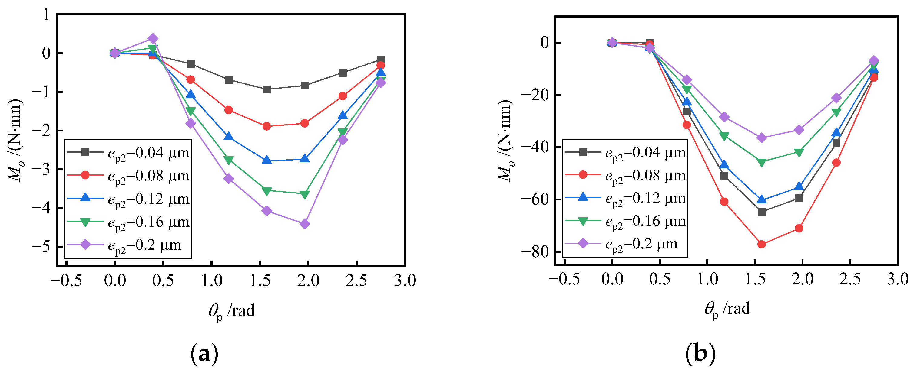
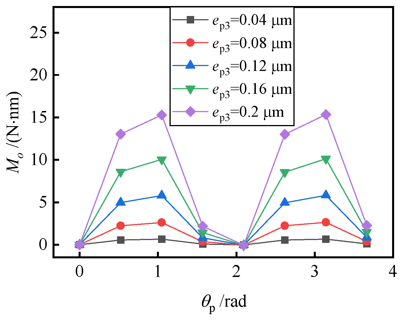
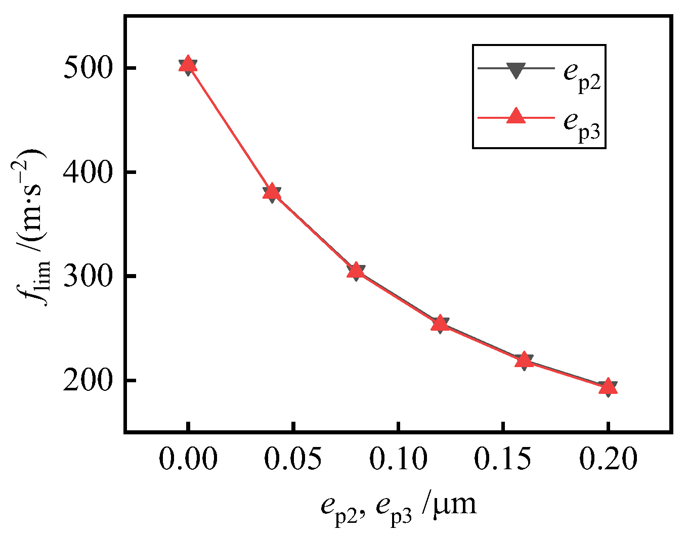
5.2. Effect of Oval Error and Trigone Error

If there is an oval error with different installation angles on both sides, the bearing is not symmetric in the circumferential direction or about the io-plane anymore. Therefore, any radial specific force may cause bearing inclination and eccentricity, resulting in interference torque. Figure 12a shows the interference torque influenced by oval error with specific force f = (10 0 0) m/s2. The interference torque increases with the increase in oval error. The five curves have the same trend. When the difference of the phase angle varies in the range π/4–7π/8, the interference torque is around the negative o-axis. When the difference of the phase angle is 0, the interference torque is 0 because of the system symmetry about the io-plane. When the difference of the phase angle is π/8, the interference torque is around the positive o-axis, which shows poor regularity caused by the interaction of oval error and the grooves. The interference torque curves with no groove on the bearing surface are shown in Figure 12b for verification, and the relationship between interference torque and phase angle shows more obvious regularity without positive interference torque.
Figure 13 presents the interference torque influenced by trigone error with specific force f = (10 0 0) m/s2, which shows two periods with phase angles varying in the range 0–2π/3. Therefore, the symmetry of the bearing and error modes does lead to the periodicity of the interference torque curve.
Figure 14 presents the overload limit with oval error or trigone error. As the overload is limited by the s-direction for the conical bearings and the phase angle does not affect the stiffness in the s-direction, the difference of the phase angle on both sides does not affect the overload limit either. The overload limit decreases with the increase in the oval error or trigone error, because the two errors cause an uneven distribution of gas film.

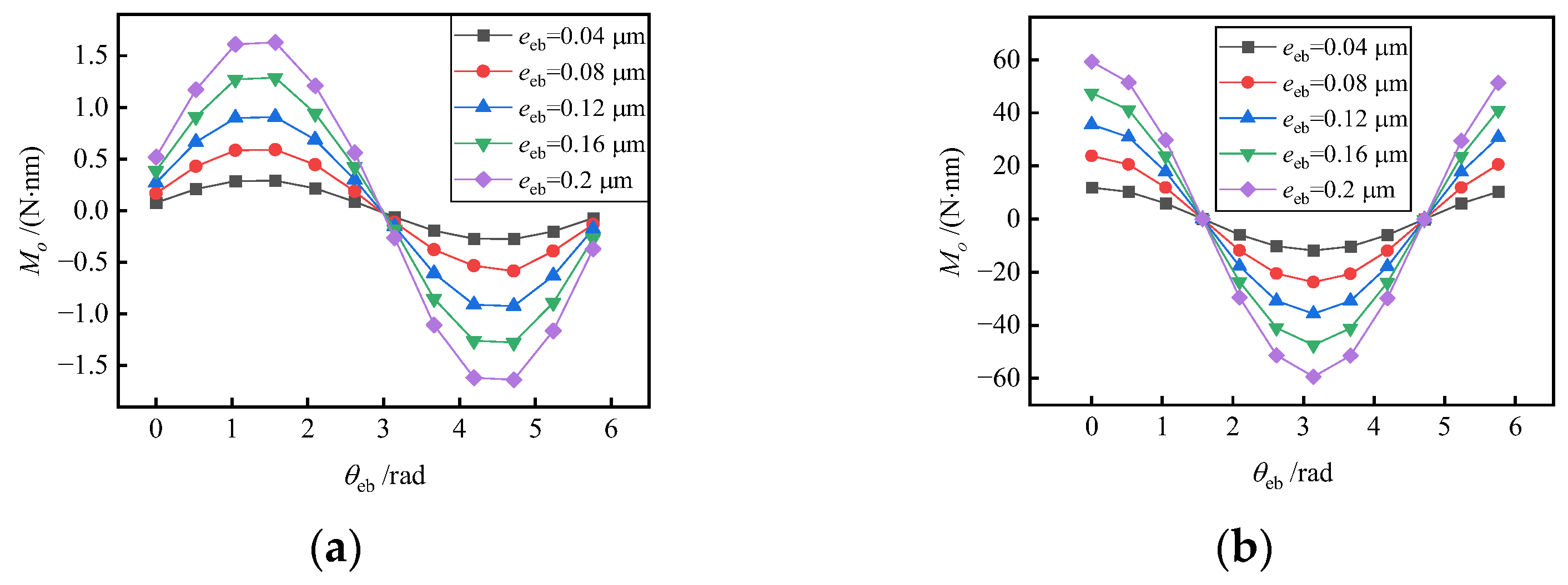
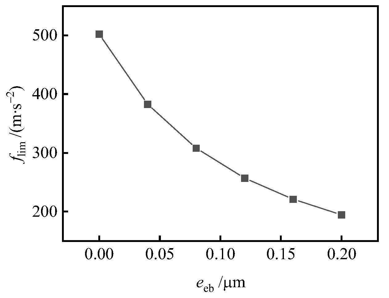
5.3. Effect of Eccentricity of the Axis

Figure 15 shows the interference torque with different radial eccentricity and attitude angles, where (a) is obtained with f = (10 0 0) m/s2, and (b) is obtained with f = (0 0 10) m/s2. As the eccentricity of the axis changes the balance position of the bearing, even only specific force in a single direction could cause the interference torque. In general, the interference torque is 100–1000 times smaller than that under the condition of both radial and axial specific forces. However, most of the time, there is only a single direction of specific force, such as the carrier straight upward acceleration. So, the interference torque caused by the eccentricity of the axis could not be ignored. It increases with the increase in the magnitude of eccentricity, and it changes in the form of a sine function with the change of attitude angle. When the eccentricity is along the i-axis with the specific force along the i-axis, the interference torque is very small. When the bearing is offset along the o-axis, the interference torque is close to the peak value. It could be explained in Figure 16, where the two circles represent the sections of the rotor and bearing, respectively. The rotor displacement caused by specific force has components along the negative i-axis and negative o-axis. When the cone in the positive s-axis has the eccentricity along the opposite direction of rotor displacement, the bearing force increases significantly, which pushes the rotor to move along the negative direction of the s-axis. Therefore, the dotted line direction corresponds to the peak value of interference torque. With a specific force along the s-axis, when the eccentricity is along the i-axis, the interference torque reaches the peak value. When the eccentricity is along the o-axis, the interference torque is 0. This is because the interference torque is only related to the rotor displacement in the i-direction with a specific fore along the s-axis, and the eccentricity of the bearing along the i-axis leads to the displacement of the rotor along the i-axis.
The relationship between the overload limit and the eccentricity of the axis is shown in Figure 17. It can be seen that the overload limit decreases with the increase in the eccentricity of the axis. The eccentricity could cause the rotor displacement and tilt without radial specific force, which leads to the uneven distribution of the gas film and reduces the load capacity of the bearing.

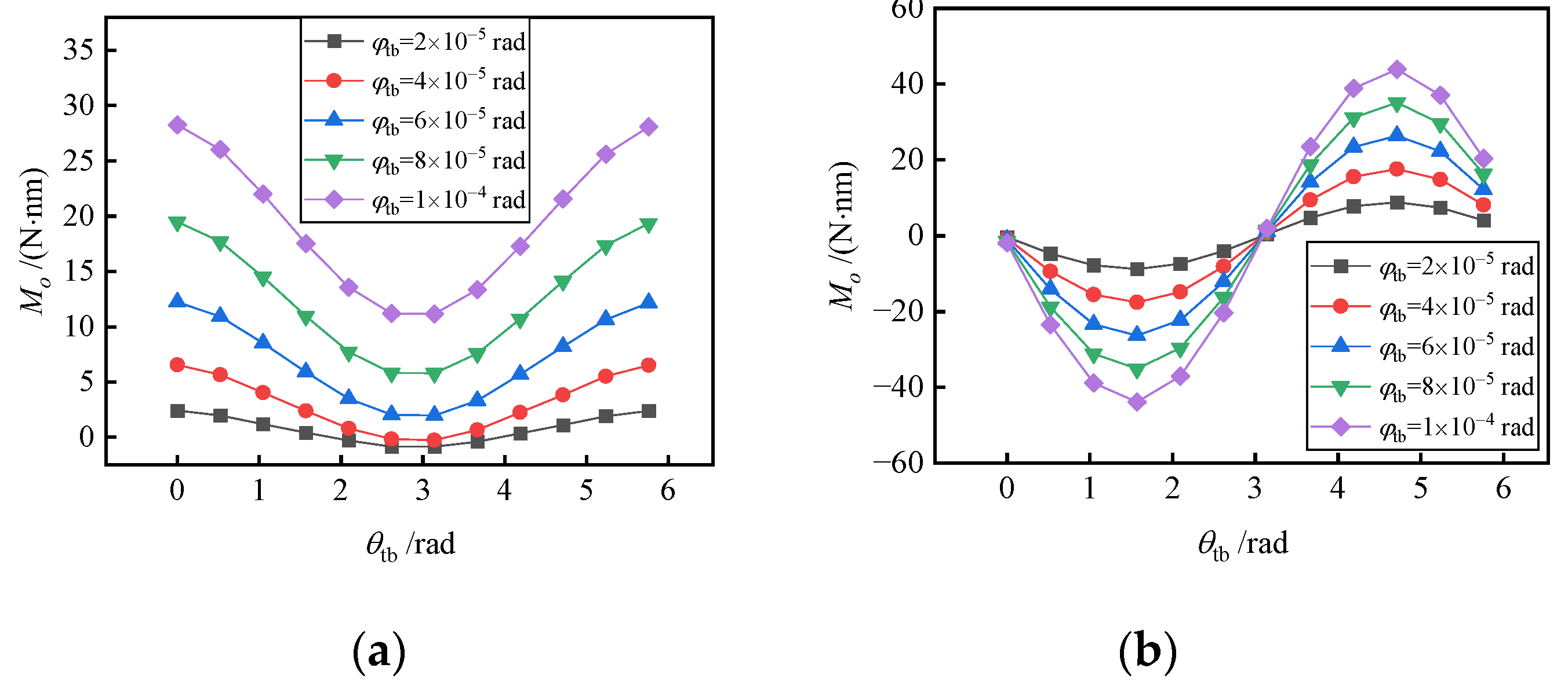
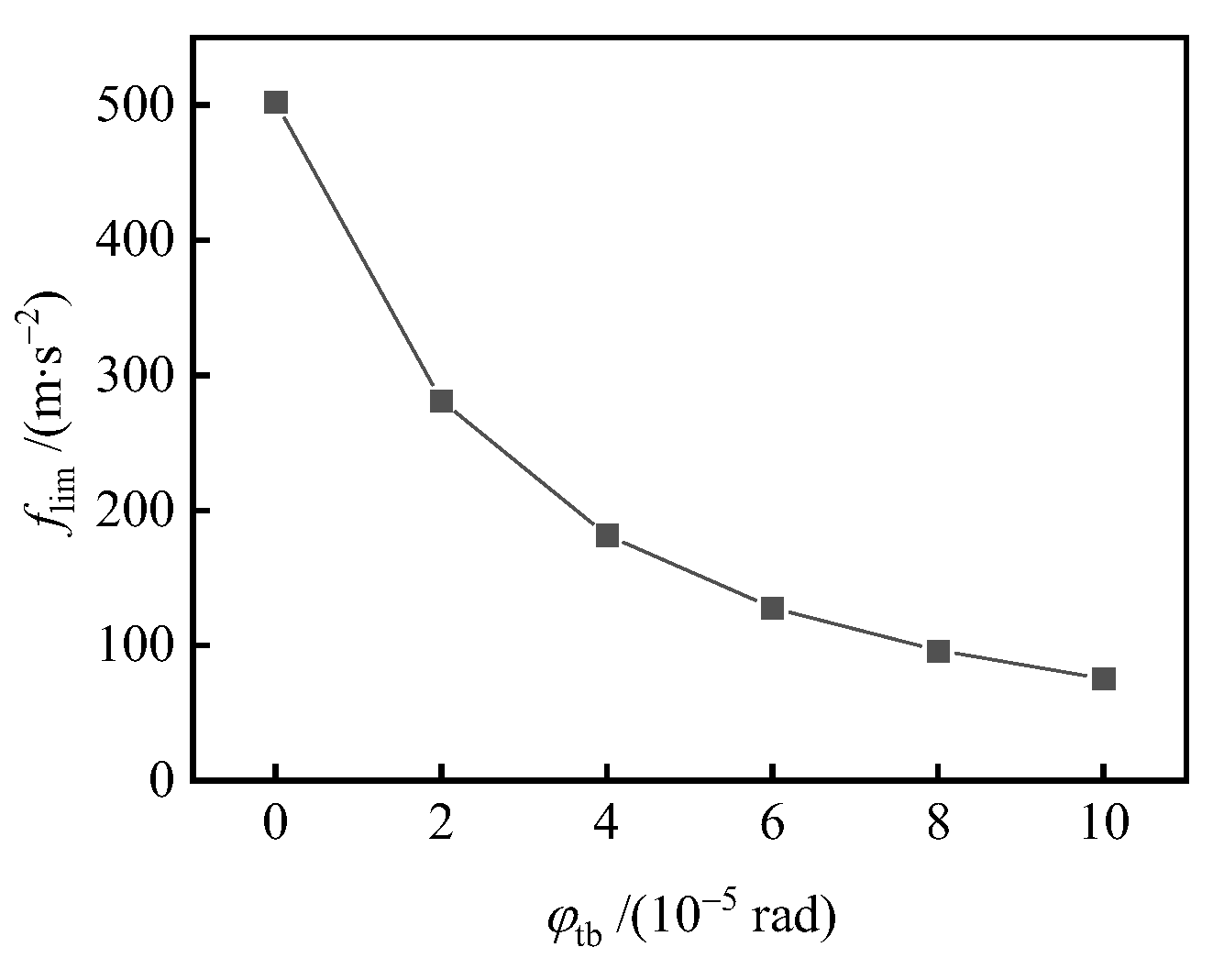
5.4. Effect of the Angular Deviation of the Axis

The interference torque caused by the angular deviation of the axis is shown in Figure 18. Figure 18a is obtained with f = (10 0 0) m/s2. In general, a larger angular deviation of the axis could cause a larger interference torque. An attitude angle close to 0 results in the maximum interference torque, while an attitude angle close to π results in the minimum interference torque. When the angular deviation is small and the attitude angle is close to π, a negative interference torque could be produced. The results could also be explained in Figure 16. Different from the above situation, even an angular deviation to the direction of thicker gas film could hardly reduce the bearing capacity, as only the inner end face moves obviously, and the outer end face almost does not move. When the offset of the inner end face is large enough, the bearing capacity will increase. Therefore, the interference moment is positive at a large angular deviation for any attitude angle.
Figure 18b is obtained with f = (0 0 10) m/s2. The interference torque increases with the increase in angular deviation, and it changes in the form of a sine function with the change of attitude angle. With a specific force in the s-axis, the interference torque depends on the rotor displacement in the i-axis. When angular deviation is around the positive o-axis, the cone is close to the negative i-axis and pushes the rotor to the same direction, so the interference torque reaches the peak value. When the angular deviation is around the positive i-axis, the rotor displacement in the i-axis is close to 0, and thus, so is the interference torque.
The relationship between the overload limit and the angular deviation of the axis is shown in Figure 19. Because the angular deviation could reduce the thrust effect of the spiral grooves, the overload limit decreases with the increase in angular deviation.

6. Conclusions

The influence of taper error, oval error, trigone error, eccentricity of the axis and angular deviation of the axis on the gas-dynamic bearing gyroscope is studied by modeling the errors as the variation of gas film thickness. The perturbation method and the iterative method are combined to solve the rotor displacement, and the interference torque caused by the manufacturing errors is investigated. The overload limit influenced by the manufacturing errors is also studied, with the standard of minimum gas film thickness as low as 1/10 of the bearing clearance. The conclusions are obtained as follows:
(1)
With the effect of manufacturing errors, even only specific force in a single direction could cause the interference torque. Taper error will cause interference torque, whether there is specific force or not. With an oval error or trigone error, radial specific force will cause interference torque. With an eccentricity or angular deviation of the axis, any specific force will cause interference torque. In general, the interference torque is small, which is 10–1000 times smaller than that under the condition of both radial and axial specific forces.
(2)
The increase in taper error, oval error, trigone error, eccentricity of the axis and angular deviation of the axis will increase the interference torque and reduce the ultimate overload, because they cause uneven distribution of gas film. When the attitude angle of bearing axis eccentricity and angular deviation changes, the interference torque will change periodically and may be 0, but the installation angle corresponding to the 0 point is different under different working conditions.
(3)
Among the manufacturing errors studied in this paper, the taper error has the greatest influence on the gas-dynamic bearing gyroscope. With the taper error up to 1.5 × 10⁻⁴, the interference torque under the condition of f = (10 0 0) m/s2 could reach 100 N·nm, and the overload limit will be reduced to less than 100 m/s2.
The results and conclusions could provide theoretical guidance for the design of gas-dynamic bearing gyroscopes.

Author Contributions

Methodology, Y.L.; software, Y.L.; formal analysis, Y.N.; investigation, Y.N.; data curation, Y.N.; writing—original draft preparation, Y.L.; writing—review and editing, Y.N.; visualization, Y.N.; supervision, D.Z.; project administration, D.Z.; funding acquisition, D.Z. and Y.L. All authors have read and agreed to the published version of the manuscript.

Funding

This research was funded by the National Natural Science Foundation of China, grant numbers U2106225, 52005224, Jiangsu Distinguished Youth Fund, grant number BK20211547, and 2021 excellent scientific and technological innovation team project of universities in Jiangsu Province, grant number SKJ (2021)-1.

Institutional Review Board Statement

Not applicable.

Informed Consent Statement

Not applicable.

Data Availability Statement

Not applicable.

Conflicts of Interest

The authors declare no conflict of interest. The funders had no role in the design of the study; in the collection, analyses, or interpretation of data; in the writing of the manuscript; or in the decision to publish the results.

Nomenclature

bBearing widthi, o, sCoordinates in the input axis, output axis, spin axis respectively
cBearing clearancekTapper
dDistance between the two conesmMass of the rotor
ep2Oval error, the difference between the major axis and the minor axisMoInterference torque
ep3Trigone errornrRotating speed
eebthe eccentricity of the axis of the conenξNormal unit vector of the bearing surface
RBottom radiusNgNumber of grooves
fSpecific forcepGas film pressure
fs0Initial specific forceQPoiseuille flow rate coefficient
flimUltimate overloaduRotor eccentric displacement
FfgApparent gravityμGas viscosity
FsgSupported forceφRotor tilting angle
FfrApparent gravityξCone surfaces index
hGas film thicknessθpDifference of the phase angle between the two sides for oval error and trigone error
hminMinimum film thicknessθebAttitude angle
hFilm thickness variationβgAttitude angle of grooves
hgGroove depthωRotating speed

References

  1. Feng, K.; Huang, Z.; Guo, Z.-Y. Design of spherical spiral groove bearings for a high-speed air-lubricated gyroscope. Tribol. Trans. 2015, 58, 1084–1095. [Google Scholar] [CrossRef]
  2. Hu, H.; Feng, M.; Ren, T. Effect of taper error on the performance of gas foil conical bearing. Ind. Lubr. Tribol. 2020, 72, 1189–1197. [Google Scholar] [CrossRef]
  3. Nielsen, B.B. Combining Gas Bearing and Smart Material Technologies for Improved Machine Performance Theory and Experiment. Ph.D. Thesis, Technical University of Denmark, Lyngby, Denmark, 2017. [Google Scholar]
  4. Nielsen, B.B.; Santos, I.F. Transient and steady state behaviour of elasto–aerodynamic air foil bearings, considering bump foil compliance and top foil inertia and flexibility: A numerical investigation. Proc. Inst. Mech. Eng. Part J-J. Eng. Tribol. 2017, 231, 1235–1253. [Google Scholar] [CrossRef]
  5. Liu, W.; Baettig, P.; Wagner, P.H.; Schiffmann, J. Nonlinear study on a rigid rotor supported by herringbone grooved gas bearings: Theory and validation. Mech. Syst. Signal Process. 2021, 146, 106983. [Google Scholar] [CrossRef]
  6. Zhang, X.-Q.; Wang, X.-L.; Si, L.-N.; Liu, Y.-D.; Shi, W.-T.; Xiong, G.-J. Effects of temperature on nonlinear dynamic behavior of gas journal bearing-rotor systems for microengine. Tribol. Trans. 2016, 59, 944–956. [Google Scholar] [CrossRef]
  7. Bailey, N.; Hibberd, S.; Power, H. Dynamics of a small gap gas lubricated bearing with Navier slip boundary conditions. J. Fluid Mech. 2017, 818, 68–99. [Google Scholar] [CrossRef] [Green Version]
  8. Tkacz, E.; Kozanecki, Z.; Kozanecka, D.; Łagodziński, J. A self-acting gas journal bearing with a flexibly supported foil - numerical model of bearing dynamics. Int. J. Struct. Stab. Dyn. 2017, 17, 1740012. [Google Scholar] [CrossRef]
  9. Du, J.; Yang, G.; Ge, W.; Liu, T. Nonlinear dynamic analysis of a rigid rotor supported by a spiral-grooved opposed-hemisphere gas bearing. Tribol. Trans. 2016, 59, 781–800. [Google Scholar] [CrossRef]
  10. Pronobis, T.; Liebich, R. Comparison of stability limits obtained by time integration and perturbation approach for gas foil bearings. J. Sound Vib. 2019, 458, 497–509. [Google Scholar] [CrossRef]
  11. Feng, K.; Li, W.-J.; Xie, Y.-Q.; Liu, M.-X. Theoretical analysis of the slip flow effect on gas-lubricated micro spherical spiral groove bearings for machinery gyroscope. Microsyst. Technol. 2016, 22, 387–399. [Google Scholar] [CrossRef]
  12. Feng, K.; Li, W.J.; Wu, S.B.; Liu, W.H. Thermohydrodynamic analysis of micro spherical spiral groove gas bearings under slip flow and surface roughness coupling effect. Microsyst. Technol. 2017, 23, 1779–1792. [Google Scholar] [CrossRef]
  13. Li, Y.; Duan, F. Interference torque of a three-floated gyroscope with gas-lubricated bearings subject to a sudden change of the specific force. Chin. J. Aeronaut. 2019, 32, 737–747. [Google Scholar] [CrossRef]
  14. Li, Y.; Duan, F. Static error model of a gyroscope with gas-dynamic hemispherical bearings. J. Beijing Univ. Aeronaut. Astronaut. 2018, 44, 1705–1711. [Google Scholar]
  15. Guenat, E.; Schiffmann, J. Multi-objective optimization of grooved gas journal bearings for robustness in manufacturing tolerances. Tribol. Trans. 2019, 62, 1041–1050. [Google Scholar] [CrossRef]
  16. Liu, J. Research on Influencing Factors of Interference Torque of Gas-Floated Gyroscope. Ph.D. Thesis, Harbin Institute of Technology, Harbin, China, 2011. [Google Scholar]
  17. Liang, Y.; Liu, J.; Sun, Y.; Lu, L. Surface roughness effects on vortex torque of air supported gyroscope. Chin. J. Aeronaut. 2011, 24, 90–95. [Google Scholar] [CrossRef] [Green Version]
  18. Yang, G. Research on Dynamic Characteristics of Gas Bearing Rotor System for Gyroscope. Ph.D. Thesis, Harbin Institute of Technology, Harbin, China, 2017. [Google Scholar]
  19. Li, H.; Yu, H.; Zhang, G.; Zhao, H.; Ma, W. Effect of elliptical error on the characteristics of porous aerostatic journal bearings. Manuf. Technol. Mach. Tool 2015, 6, 84–87. [Google Scholar]
  20. Ren, T.; Feng, M.; Hu, M.; Liu, Z. Influence of machining errors on stiffness of hydrodynamic gas bearing in gyroscope motor. J. Chin. Inert. Technol. 2019, 27, 378–383. [Google Scholar]
  21. Li, Y.; Zhang, D.; Duan, F. Interference torque of a gas-dynamic bearing gyroscope subject to a uniform change of the specific force and the carrier angular velocity. Sensors 2020, 20, 6852. [Google Scholar] [CrossRef] [PubMed]
  22. Li, Y.; Duan, F.; Fan, L.; Yan, Y. Static error model of a three-floated gyroscope with a rotor supported on gas-lubricated bearings. Proc. Inst. Mech. Eng. Part C-J. Mech. Eng. Sci. 2018, 232, 2850–2860. [Google Scholar] [CrossRef]
  23. Li, Y.; Zhang, D.; Duan, F. Dynamic characteristics of opposed-conical gas-dynamic bearings. Ind. Lubr. Tribol. 2019, 72, 415–425. [Google Scholar] [CrossRef]
Figure 1. The schematic structure of the gas-dynamic bearing gyroscope.
Machines 10 01010 g001
Figure 2. The configuration of the gas-dynamic bearing.
Machines 10 01010 g002
Figure 3. Schematic of bearing taper error.
Machines 10 01010 g003
Figure 4. Schematic of oval error and trigone error of bearing: (a) front view, (b) oval error, (c) trigone error.
Machines 10 01010 g004
Figure 5. Schematic of eccentric error of bearing installation axis.
Machines 10 01010 g005
Figure 6. Schematic of angular deviation of the axis.
Machines 10 01010 g006
Figure 7. Schematic of the interference torque generation.
Machines 10 01010 g007
Figure 8. Program flow chart for calculating interference torque.
Machines 10 01010 g008
Figure 9. Program flow chart for calculating overload limit.
Machines 10 01010 g009
Figure 10. Interference torque versus taper error.
Machines 10 01010 g010
Figure 11. Overload limit versus taper error.
Machines 10 01010 g011
Figure 12. Interference torque versus oval error. (a) with grooves (b) without grooves.
Machines 10 01010 g012
Figure 13. Interference torque versus trigone error.
Machines 10 01010 g013
Figure 14. Overload limit versus oval error and trigone error.
Machines 10 01010 g014
Figure 15. Interference torque versus eccentricity of the axis. (a) with f = (10 0 0) m/s2 (b) with f = (0 0 10) m/s2.
Machines 10 01010 g015
Figure 16. Schematic position of the rotor and high pressure region on a cross-section.
Machines 10 01010 g016
Figure 17. Overload limit versus eccentricity of the axis.
Machines 10 01010 g017
Figure 18. Interference torque versus the angular deviation of the axis. (a) with f = (10 0 0) m/s2 (b) with f = (0 0 10) m/s2.
Machines 10 01010 g018
Figure 19. Overload limit versus the angular deviation of the axis.
Machines 10 01010 g019
Table 1. Parameters for calculation of the gas-dynamic bearing gyroscope.
ParametersValues
Bottom radius R/mm7.5
Tapper k0.25
Bearing width b/mm6.0
Bearing clearance c/μm2.0
Distance between the two cones d/mm8.0
Groove depth hg/μm0.5
Number of grooves Ng6.0
Attitude angle of grooves βg45
Rotor mass m/g60
Viscosity μ/(Pa∙s)1.79 × 10−5
Rotating speed nr/(r∙min−1)30,000
Ambient pressure Pa/Pa1.013 × 105
Publisher’s Note: MDPI stays neutral with regard to jurisdictional claims in published maps and institutional affiliations.

