Article

A Numerical Analysis of Hybrid Spur Gears with Asymmetric Teeth: Stress and Dynamic Behavior

1
Department of Motor Vehicles and Transportation Technologies, Bursa Uludag University, 16850 Bursa, Turkey
2
Department of Mechanical Engineering, Bursa Uludag University, 16059 Bursa, Turkey
*
Author to whom correspondence should be addressed.
Machines 2022, 10(11), 1056; https://doi.org/10.3390/machines10111056
Submission received: 8 October 2022 / Revised: 30 October 2022 / Accepted: 2 November 2022 / Published: 10 November 2022
(This article belongs to the Section Machine Design and Theory)

Abstract

:
Hybrid gears are composed of high-strength steel, carbon fiber reinforced plastic (CFRP), and adhesive bond to join these materials. In this study, the effect of rack tip radius (TR), drive side pressure angle (DSPA), and rim thickness (RT) on the stress of hybrid gears is investigated numerically. In addition, the stress results of hybrid gears are compared with steel gears that are used for validation of the numerical results. Single tooth stiffness (STS) values are calculated based on tooth deformations obtained from numerical analyses. The 2-DOF model is used to observe the influence of DSPA and RT on the dynamic factor (DF) and static transmission error (STE). According to the results, increasing RT has a positive effect on stress, STS, and STE, while DSPA is effective on the dynamic factor at most.

1. Introduction

Gears are the most widely used powertrains in terms of utilization rate and application area. Due to the continuous and smooth transfer of power and motion and the constant ratio, gears are utilized from huge machines to the most miniature clock mechanisms. With several advantages, involute gears are the most often used gear [1,2]. With the developing technology, expectations have arisen to provide higher power and moment transmission from involute gears. For this purpose, designers have focused their work on different gear geometries. Gear geometry research has primarily concentrated on asymmetric involute gears. When comparing the symmetric gears, larger loads per unit facewidth can be carried by gear with asymmetric teeth [3,4].
Another significant goal in the industrial sectors, such as automotive, aviation, and machinery, where involute gears are the key transmission elements, is to reduce the amount of fuel usage and, consequently, the CO2 emission rate [5]. The total structural mass of a product is the most responsible factor in the amount of fuel usage. The easiest method of the lightweighting process is to replace the material with a lower density one [6,7]. Most automotive and machine parts subjected to low stresses were previously made from steel but are now made from aluminum, magnesium, or composites [8,9,10]. For gears, usage of these light materials is limited due to higher stress during the power transmission. Gear steel grades are still the most proper options. Indeed, Hertzian stresses occur on the contact zone, as well as bending stress on the tooth root zone for spur gears during operation. Except for these certain zones, the stress levels are quite low [11,12]. For these reasons, a lightweight material can be used for the low stress zone. Mesh stiffness (MS) is another crucial factor for spur gears since it directly affects transmission error and dynamic behavior. Carbon fiber reinforced polymers (CFRP) can be used for the low-stress zone with their high rigidity and good NVH properties. For decades, CFRP materials have been utilized as the material of engineering structures in aerospace, automotive, and other industries [13,14].
Within NASA’s Glenn Research Center, the first significant research was started for gear production. Handschuh and his colleagues developed and experienced a prototype hybrid gear. To connect steel and composite, a bonding method was utilized. To compare full steel and hybrid gear, numerical and experimental methods were utilized to get critical frequencies. Furthermore, vibration and sound levels for various driven-driving gear material combinations were measured using dynamics experiments for a variety of torque and rpm levels. There was no apparent fatigue damage for conducted rpm and torque values, according to the results. The critical frequencies were found to be lesser than complete steel gear. Total mass was reduced by 20%, approximately. According to these tests, stress and fatigue damage to hybrid gears is not a significant issue, provided the rim thickness value is properly adjusted [15,16]. Catera et al. suggested a FE-based method for CFRP to determine the critical velocities of hybrid gear. The proposed method was verified with previous experimental data. Catera et al. used FE research to determine stress on the root and joint region for hybrid gear subjected to large loads. Different modeling approaches were compared. The acquired values of these two techniques were quite similar, according to the results. When compared to thin rimmed-thin webbed steel gear of the same weight, hybrid gears have reduced maximum STE values [17,18]. Catera et al. performed a comparison study to understand how two alternative connecting procedures affected the vibration of hybrid gears. According to the findings, adhesive bonding is superior with greater damping capabilities. However, the interference fitting method ensures higher tooth stiffness. The numerical results were merged with experimental data [19]. For the identical ring rim thicknesses, Karpat et al. evaluated the stress, stiffness, and weight status of gears with aluminum and composite materials used for low stress zone [20]. Gauntt and Campell examined different laminas and ply sequences. The natural frequency is significantly affected by the elasticity modulus, according to the findings [21]. Yılmaz et al. conducted comprehensive study to evaluate performance of hybrid gears with symmetric teeth. The moment transmission capacity of hybrid gears was determined based on stress values [22].
In these aforementioned studies, fixed parameters were utilized to design hybrid gears. There is a gap in the literature about the effect of TR and DSPA for hybrid gears, especially. In this study, stress, stiffness, STE, and DF of hybrid gears with different design parameters are investigated, numerically.

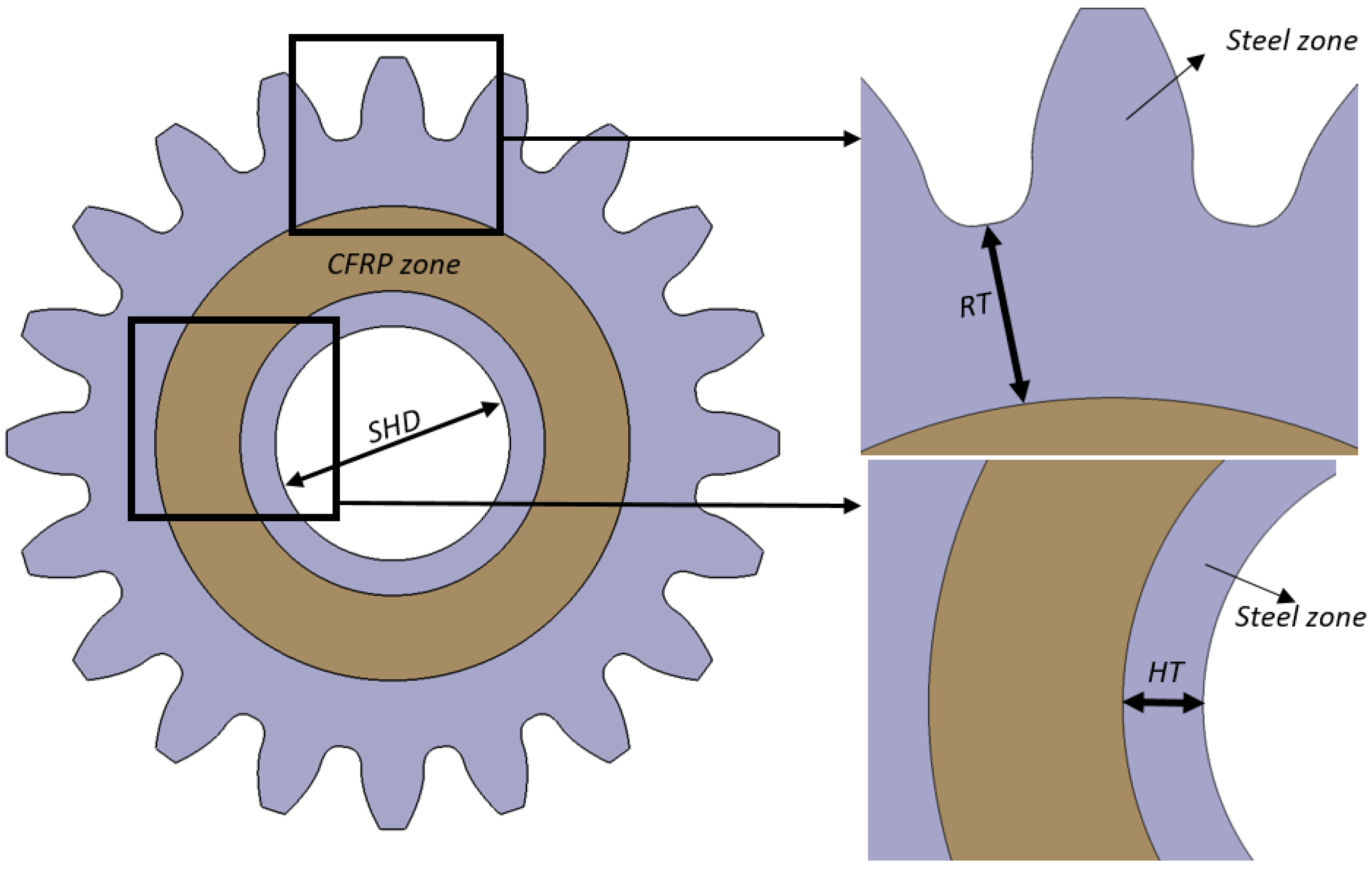
2. Materials and Methods

The failure modes of spur gears are directly related to the stress on the involute flank and tooth root region [23]. For this reason, stress values have to be calculated to configure and control the parameters of spur gears. There are many ways to find tooth stress in the literature. DIN3990 and AGMA are the most popular standard analytical methods for root stress calculation [24,25]. However, these methods’ accuracy is insufficient for non-standard gear designs. The finite element method (FEM) is a highly preferred tool to determine the stress status of spur gears with different designs and materials combinations [26,27,28]. For this reason, FEM is utilized to evaluate the stress of hybrid gears in this study. The coordinates of gear tooth points are the output of prepared MATLAB code which includes mathematical equations of spur gear based on Litvin’s approach [1], which are imported to the CATIA V5 program to design 3D models. In Table 1, the values of gear parameters used in analyses are presented.
In Figure 1 and Figure 2, the finite element gear models of spur gears for stress analyses are illustrated [29].
The material of the tooth-rim and hub regions of hybrid gears are assigned as steel with isotropic properties. Elasticity modulus € and Poisson’s ratio (υ) are defined as 210 GPa and 0.3, respectively. CFRP material on the web region of the gear is modeled as an orthotropic homogeneous core. M46J carbon fiber [18] and epoxy material [18] with 53% and 47% volume mixture ratio, respectively, are used to constitute 12 unidirectional (UD) laminas. Ply thickness is selected as 2 mm. These laminas are arranged in a symmetric sequence [0/30/60/90/−60/−30]s to constitute CFRP laminate with quasi-isotropic properties in-plane. In Table 2, the material constants of CFRP laminate that are used in the analyses are presented [22].
For hybrid gears, it is evaluated that steel and CFRP parts are joined with adhesive bonding. The adhesive is modeled with cohesive zone material (CZM). The CZM method can estimate the strength of adhesive without requiring any initial defect. A well-known fact is that spur gears are planar loaded (bidirectional loading) machine elements during the power transmission [22,29]. These loads result in stresses in the normal and tangential directions for root and joint regions. For this reason, the adhesive is modeled as zero thickness material according to the rule of mixed mode (Mode I + Mode II) condition in the stress analyses. Details of the stress-deformation relation of adhesives can be found in the literature [30,31]. In Table 3, CZM properties are presented.
High order 3D 20 node Solid186 mesh elements are used to discrete steel and CFRP parts with element size 0.3 in the finite element model. TARGE170 and CONTA174 are used to distinguish between steel and CFRP parts. The normal force (FN) (147.8 N) is applied to the upper radius of single tooth contact, which is called HPSTC. Equation of the component of normal force is given in the Appendix B. The gear was fixed from the shaft hole in terms of rotation and displacement for each direction. The load and support situation of FEM are illustrated in Figure 3.

2.1. Stiffness Evaluation

Mesh stiffness is the key parameter for the dynamic performance of the gear systems. Mesh stiffness is related to tooth stiffness directly. In spur gears, the tooth stiffness can be determined as the rate of applied load to total deformation. These deformations are the sum of bending, shearing, compression, and rim and the local Hertz deformations resulting from contact [32]. Deformations are directly related to the stiffness of the gear. These deformations can be obtained analytically [33,34], by the finite element method [35,36] or experimentally [37,38]. In this study, a FE method that is experimentally validated for steel and plastic gears [39,40] is used to evaluate the tooth deformation of hybrid gears. The adhesive bonding zone is modeled with a thickness of 0.25 mm [19]. While the mesh element type remains the same as in the stress analysis, the mesh element size is selected as 0.15 mm in order to involve the effect of hertz deformation [41]. Bonded contact is used between adhesive and CFRP-steel parts. Contact force (F) is defined as 100 N and applied sequentially from different radii along the involute curve on the drive side. The fixed support condition is also identical to stress analysis. The load and support conditions of the deformation analysis are shown in Figure 4.
After obtaining the deformations for different gear parameters, the single tooth stiffnesses are obtained by dividing these deformations by the applied force (Equations (1)–(4)).
k p 1 = F 1 x p 1
k d 1 = F 1 x d ı
k p 2 = F 2 x p 2
k d 2 = F 2 x d 2
where x represents the total deformation value obtained from ANSYS, p1 represents the first pinion in contact, p2 represents the second pinion in contact, and d1 and d2 represent the first and second gear teeth in contact, respectively. Obtained single tooth stiffness (STS) values are found for different radii. Depending on the radius, stiffness curves are fitted with high precision (εave < 0.002). The equation of these curves is used in determining the mesh stiffness as an input in the dynamic analyses. Gear pairs in contact can be considered as springs in series. If two gear pairs are in contact at the same time, then these gear pairs can also be modeled as springs in parallel (Figure 5). Mesh stiffness of gear tooth pairs is given in the following equations.
Stiffness of first gear pair
K 1 = k p 1 k d 1 k p 1 + k d 1
Stiffness of second gear pair
K 2 = k p 2 k d 2 k p 2 + k d 2
If there is a single tooth contact, the mesh stiffness;
K = K 1
If there is a double tooth contact, the mesh stiffness;
K = K 1 + K 2

2.2. Dynamic Behavior Evaluation

As the number of revolutions increases, dynamic loads begin to be effective on the gear in the gear mechanisms. The determination of these dynamic loads according to the number of revolutions is rather significant in gear mechanism design [42]. In addition, minimization of dynamic loads is required, especially at a high number of revolutions. In gear dynamics, the concept of dynamic factor is generally used to explain the dynamic behavior of the gear pairs. The dynamic factor is the ratio of the maximum dynamic load to the static load during a cycle [43,44,45]. On the other side, STE is accepted as a primary cause of vibration and noise in gear systems. STE is also one of the most significant indicators for the performance evaluation of gear pairs [18,46]. The 2-DOF model is used to examine the hybrid gears’ dynamic behavior in the current study. Dynamic factors in the range of 100–45,000 rpm are found for each gear type, and static transmission errors are obtained for 1 rpm number of revolution. The equations of motion in the 2-DOF system are obtained from the free-body diagram in Figure 6.
The equilibrium equations of the gear system are presented in Equations (9) and (10).
J p θ ¨ p = T p r b p ( F 1 + F 2 ) ± ρ p 1 µ 1 F 1 ± ρ p 2 µ 2 F 2
J g θ ¨ g = r b g ( F 1 + F 2 ) T G ± ρ g 1 µ 1 F 1 ± ρ g 2 µ 2 F 2
Here, 1 and 2 indicate first and second gear pairs which are in contact position. Jp and Jg are the mass moments of inertia of the pinion and gear, θp and θg angular rotation values, T transferred moment, F dynamic load, ρp and ρg involute radii of curvature, and µ the friction coefficient. The equations of motion with the necessary transformations and damping expression are given below. The equation of motion is presented in Equation (11) while the STE value can be found by using Equation (12). The derivation of these equations can be found in the Appendix A section.
x s = ( m g m p ) F D + K 1 e 1 ( f p , 1 m g + f g , 1 m p ) + K 2 e 2 ( f p , 2 m g + f g , 2 m g ) K 1 ( f p , 1 m g + f g , 1 m p ) + K 2 ( f p , 2 m g + f g , 2 m p )
x ¨ r + 2 [ K 1 ( f p , 1 m g + f g , 1 m p ) + K 2 ( f p , 2 m g + f g , 2 m p ) m g m p ] 1 2 ξ x ˙ r + K 1 ( f p , 1 m g + f g , 1 m p ) + K 2 ( f g , 2 m g + f g , 2 m p ) m g m p x r = ( m g m p ) F D + K 1 e 1 ( f p , 1 m g + f g , 1 m p ) + K 2 e 2 ( f p , 2 m g + f g , 2 m g ) m g m p
Here, f is the factor of friction coefficient, m is the mass, ξ is the damping of gear pairs, FD is the static load, e is the profile error and xs is the static transmission error. The fourth-order Runge Kutta method is used for solving the equations in MATLAB. The damping (ξ) and friction coefficient (μ) of gear pairs are calculated as in the previous studies [12,22]. Steel and CFRP densities are selected as 7.86 g/cm3 and 1.5 g/cm3, respectively. The volume of gear regions is taken from the CAD program to calculate the mass in the equations.

3. Results and Discussion

3.1. Root and Joint Region Stress Results

3.1.1. Effect of Rack Tip Radius on Root Stress

In this study, root stress results on the drive side of the spur gear root are taken into consideration as fatigue damage initiates from this side during the transmission [47]. In Figure 7, Figure 8 and Figure 9, the effect of TR on root stress is illustrated for different RTs.
As the cutting rack TR increases, the radius of curvature of the root trochoid curve and the root thickness increase. This situation reduces root stresses. When the cutting rack TR is increased from lowest value to highest value, the stress decreases by 16%, approximately for all RT values. In addition, after 1.5 xm in hybrid gears, the stress levels change in a low value. For validation and comparison aim, standard steel gears are also analyzed for each RT value. In Figure 10, the root stress results of standard steel gears are illustrated.
According to the results, the stress values are so close between hybrid gears for 2 xm RT for each TR and standard steel gear after 2 xm RT. On the other hand, the root stress of the standard steel gear is 133.23 MPa for ρ1 = 0.3 xm. To validate the numerical result, DIN3990 Method B (details given in Appendix B) is used. The root stress is calculated as 140.20 MPa with the analytical standard (Difference is 5.2%). The results are found to be compatible with each other. The weight status for hybrid gears with each RT and steel gear is presented in Table 4. In addition, root stress results of hybrid and steel gears are given in a tabular data (Table 5) for 20° drive side pressure angle for comparison, more easily.

3.1.2. Effect of Rack Tip Radius on Joint Normal Stress

The stress of the joint region is another significant parameter to evaluate the strength of hybrid gears. There are two different stress types that occur in the joint region. One is normal stress which results from tangential load applied to teeth, and the other is shear stress occurring from the radial load. Normal stress on the joint region has a tensile character that causes the adhesive to separate from the steel region. For this reason, in the following figures, negative stress values should be taken into account. In Figure 11, Figure 12 and Figure 13, the effect of rack TR on normal stress is illustrated for different RTs. It is seen that RT is a highly effective parameter on the normal stresses. For every 0.5 xm increase in RT, the joint region’s normal stresses decrease by approximately 46%. By increasing the RT from the lowest value to the highest value, the normal stresses reduce by about 85%. In contrast to root stress results, rack tip radius has a modest effect on the joint normal stresses. When the rack TR increases from 0.1 xm to 0.3 xm, the normal stress decreases by nearly 6% for each RT value.

3.1.3. Effect of Rack Tip Radius on Joint Shear Stress

In addition to the normal stress, shear stresses also occur in the joint areas. In hybrid gears, it is very important to determine the stresses in the joint region. These stresses should be lower than the normal and shear strength value of the adhesive. In Figure 14, Figure 15 and Figure 16, the shear stress values of hybrid gears are presented. According to findings, the shear stress values decrease with increasing RT. When the results are examined, shear stress decreases nearly by 15% for each 0.5 xm increment of RT; consequently, the total reduction is 60%. On the other side, rack TR has a modest effect on joint shear stress. The maximum shear stress is 17.863 MPa for ρ1 = 0.1 xm. When the rack TR becomes 0.3 xm, this stress results decrease by only 2% for 0.5 xm RT. The rack TR effect is decreased with increasing RT. For 2 xm RT, the difference between stress levels decreases by 0.6%.

3.1.4. Effect of Drive Side Pressure Angle on Root Stress

In Figure 17 and Figure 18, the effect of DSPA on root stress of hybrid gears is illustrated for each RT. Please note that results of 20° DSPA are presented in Section 3.1.1.
The difference between the highest and lowest RT is found to be 13%, approximately. This decrease is noticeably reduced, especially after the RT value of 1.5 xm. Compared to gears with αd-αc: 20°-20° pressure angle, it is seen that the stresses are reduced by about 5% for each RT. When the DSPA is increased from 20° to 30°, root stress decreases by approximately 6%. For hybrid gears with the 30° DSPA, the difference of tooth root stresses is found approximately 12% between the highest and lowest RT. This reduction ratio is very close to hybrid gears with the 25° DSPA.

3.1.5. Effect of Drive Side Pressure Angle on Joint Normal Stress

In Figure 19 and Figure 20, the effect of DSPA on the joint normal stress is illustrated. Please note that the results of 20° DSPA are presented in Section 3.1.2.
When all DSPAs are examined, it is seen that the normal stresses decrease by 50% at each 0.5 xm increment of the RT. The effects of increasing the DSPA on normal stress are quite limited. When the DSPA is increased from 20° to 25°, the normal stresses decrease by 2.5% on average, while this ratio becomes 3.5% when increased to 30°. The effect of DSPA gets higher with the increment of RT.

3.1.6. Effect of Drive Side Pressure Angle on Joint Shear Stress

In Figure 21 and Figure 22, the effect of DSPA on the joint shear stress is illustrated. Please note that results of 20° DSPA are presented in Section 3.1.3.
Contrary to normal stress, increasing the DSPA increases the shear stress of the joint region. This is due to the increase in the radial force with the increase in the DSPA. When the DSPA increases to 25° and 30°, the shear stress increases by 6% and 13%, considering all RT values, respectively. In Table 6, stress values of hybrid gears for different DSPAs and RTs are also given for comparison aim in a tabular data.

3.2. Single Tooth and Mesh Stiffness Results

In Figure 23, STE curves are presented for hybrid gears with various DSPAs and RTes. When the Figure is examined, it is seen that single tooth stiffness increases in all gears from tooth tip to tooth bottom. In addition, as the RT increases, the single tooth stiffness also increases. After 1.5 xm for αd = 20°–25°and after 1 xm for 30°, the effect of RT on single tooth stiffness decreases considerably. DSPA is another crucial parameter that affects tooth stiffness. When the DSPA is increased from 20° to 25°, the average single tooth stiffness increases by 5%, and when it is increased to 30°, this ratio becomes 20%.
Increasing RT enhances the steel zone of hybrid gear. According to the results, the MS increases with the increase of the RT. After 1.5 xm RT for 20° and 25° DSPA and 1 xm RT for 30° pressure angle, the effect of the RT on mesh stiffness decreases significantly. This is because the composite region moves away from the load area. On the other side, as the DSPA increases, the mesh stiffness increases (Figure 24). When the DSPA is increased from 20° to 25° in the region of double tooth contact, the average mesh stiffness increases by 12%. This rate is 22% at 30°. There is an increase of 20%, 33%, and 40%, respectively, for the DSPAs of 20°, 25°, and 30° in the double tooth contact region between the highest and lowest RT.

3.3. Dynamic Analysis Results

3.3.1. Dynamic Factor Results

It is obtained from Figure 25 that the RT does not have a significant effect on the dynamic factor. Although the differences are very small, they are only noticed for the resonance rpms. For 0.5 xm RT at 20° DSPA, the second resonance speed is approximately 26,000 rpm, while in 2 xm, this value is approximately 28,000 rpm. In addition, as the DSPA increases, the general resonance region is shifted to higher speeds. While the first resonance region at 20° is between 5000 and 10,000 rpms, this value is around 20,000 rpms at 30°. In fact, this situation is the result of the decrease in the contact ratio depending on the increasing pressure angle.

3.3.2. Static Transmission Error Results

When Figure 26 is examined, it is seen that with the increase of RT in hybrid gears, static transmission errors decrease for different DSPAs. In addition, the width of the single tooth contact area increases as the DSPA increases. The reason for this is the decrease in the contact ratio. Again, for the same RT, the increase in the DSPA decreases the maximum static transmission error in the single tooth region. Maximum static transmission error is approximately 9.5 μm for 20° and RT of 0.5 xm, while this value is 8.5 μm at 30°. At 2 xm RT, these values are 7.7 μm and 6.4 μm, respectively. While the effect of RT is quite evident at 0.5 xm, this effect decreases considerably after 1.5 xm for 20° and 25° DSPA and after 1 xm at 30°.

4. Conclusions

In this study, the effect of gear parameters on stress, stiffness, and dynamic behavior of hybrid gears was investigated numerically. Significant results are listed below:
  • As the RT increases, the root stresses decrease; however, this decrease reduces significantly after 1.5 xm RT.
  • The effect of RT on joint region normal stresses is higher than its effect on shear stresses. When the RT is increased from 0.5 xm to 2 xm, the normal stresses decrease by about 80%, while this ratio remains at the level of 65% in shear stresses.
  • When the increased DSPA is increased from 20° to 25°, the root stresses decrease by 5% at the same moment transmission and by approximately 9% when it is increased to 30°.
  • Increasing DSPAs for the same RT reduces the normal stresses of the joint region. However, this effect remains quite low. When the DSPA is increased to 25°, the normal stresses decrease by 2.5%, while this ratio becomes 3.5% for 30°.
  • For the same RT, increasing DSPAs increases the joint region shear stresses. When the DSPA is increased to 25°, the shear stresses increase by 6%, while this ratio becomes 13% for 30°.
  • STS and MS increase with increasing RT. When the RT is increased from 0.5 xm to 2 xm for all DSPAs, single tooth stiffness increases by approximately 20%.
  • Increasing DSPA also increases STS and MS. When the DSPA is increased to 25°, the single tooth stiffness is 5% on average, while this ratio becomes 30% at 30°.
  • When the DSPA is increased to 25°, MS increases by 12%, while this ratio becomes 22% on average at 30° averagely.
  • Mesh stiffness increases by 20%, 33%, and 40% for 20°, 25°, and 30° DSPAs, respectively.
  • Increasing RT does not significantly affect the dynamic factor. It is observed that the location of the resonance regions changes.
  • Increasing the DSPA increases the dynamic factor. In the first resonance region, the dynamic factor is about 1.45 for 20°, while the dynamic factor is about 1.8 for 30°.
  • Static transmission errors decrease as the RT and DSPA are increased. While the maximum static transmission error is approximately 9.5 μm for 20° and RT of 0.5 xm in hybrid gears, this value is 8.5 μm at 30°. At 2 xm RT, these values are 7.7 μm and 6.4 μm, respectively.

Author Contributions

Conceptualization, T.G.Y. and F.K.; methodology, T.G.Y. and F.K.; software, T.G.Y.; investigation, T.G.Y.; resources, T.G.Y. and F.K.; writing—original draft preparation, T.G.Y.; writing—review and editing, T.G.Y. and G.K.; All authors have read and agreed to the published version of the manuscript.

Funding

This research received no external funding.

Data Availability Statement

Not applicable.

Conflicts of Interest

The authors declare no conflict of interest.

Appendix A

Governing equations for 2-DOF dynamic analysis of spur gear pair
J p θ ¨ p = T p r b p ( F 1 + F 2 ) ± ρ p , 1 µ 1 F 1 ± ρ p , 2 µ 2 F 2
J p θ ¨ g = r b g ( F 1 + F 2 ) T G ± ρ g , 1 µ 1 F 1 ± ρ g , 2 µ 2 F 2  
x p = r b p θ p
x g = r b g θ g
m p = J p r b p 2
m g = J g r b g 2
F D = T g r b g = T p r b p
m P x ¨ p = F D ( F 1 + F 2 ) ± ρ p , 1 µ 1 F 1 r b p ± ρ p , 2 µ 2 F 2 r b p
m g x ¨ g = ( F 1 + F 2 ) F D ± ρ g , 1 µ 1 F 1 r b g ± ρ g , 2 µ 2 F 2 r b g
If equations are arranged,
x ¨ p = 1 m P F D 1 m P ( F 1 + F 2 ) ± 1 m P ρ p , 1 µ 1 F 1 r b p ± 1 m P ρ p , 2 µ 2 F 2 r b p
x ¨ g = 1 m g ( F 1 + F 2 ) 1 m g F D ± 1 m g ρ g , 1 µ 1 F 1 r b g ± 1 m g ρ g , 2 µ 2 F 2 r b g
If Equations (A10) and (A11) subtract each other,
x ¨ p x ¨ g = F D ( 1 m P + 1 m g ) ( F 1 + F 2 ) ( 1 m P + 1 m g ) ± F 1 m P ( ρ p , 1 µ 1 r b p ) F 1 m g ( ρ g , 1 µ 1 r b g ) ± F 2 m P ( ρ p , 2 µ 2 r b p ) F 2 m g ( ρ g , 2 µ 2 r b g )
x ¨ p x ¨ g = F 1 m P ( 1 ± ρ p , 1 µ 1 r b p ) F 1 m g ( 1 ± ρ g , 1 µ 1 r b g ) + F D ( 1 m P + 1 m g ) F 2 m P ( 1 ± ρ p , 2 µ 2 r b p )
The coefficient of friction factors can be written as:
f p , 1 = 1 ± ρ p , 1 µ 1 r b p
f p , 2 = 1 ± ρ p , 2 µ 2 r b p
f g , 1 = 1 ± ρ g , 1 µ 1 r b g
f g , 2 = 1 ± ρ g , 2 µ 2 r b g
The relative displacement, speed, and acceleration can be expressed as follows:
x r = x p x g
x ˙ r = x ˙ p x ˙ g
x ¨ r = x ¨ p x ¨ g
Total profile error can be described as:
e 1 = e g 1 + e p 1
e 2 = e g 2 + e p 2
The dynamic load between two teeth is defined:
F 1 = K 1 ( x r e 1 )
F 2 = K 2 ( x r e 2 )
In the study, involute profile errors are neglected. If the expressions in Equations (A14)–(A24) are written in Equation (A13), the new form of the equation of motion can be obtained as:
x ¨ r = ( f p , 1 m P + f g , 1 m g ) K 1 ( x r e 1 ) + F D ( 1 m P + 1 m g ) ( f p , 2 m P + f g , 2 m g ) K 2 ( x r e 2 )
x ¨ r + [ ( f p , 1 m P + f g , 1 m g ) K 1 + ( f p , 2 m P + f g , 2 m g ) K 2 ] x r = ( f p , 1 m P + f g , 1 m g ) K 1 e 1 + ( f p , 2 m P + f g , 2 m g ) K 2 e 2 + F D ( 1 m P + 1 m g )
x ¨ r + K 1 ( f p , 1 m g + f g , 1 m p ) + K 2 ( f p , 2 m g + f g , 2 m p ) m g m p x r = ( m g m p ) F D + K 1 e 1 ( f p , 1 m g + f g , 1 m p ) + K 2 e 2 ( f p , 2 m g + f g , 2 m g ) m g m p
Artificial damping is included in the equation of motion by considering the viscous damped linear systems. The general form of this equation can be expressed in the following equation.
x ¨ r + 2 ω n ξ x ˙ r + ω n 2 x r = ω n 2 x s
The natural frequencies of the system can be written as:
ω n 2 = K 1 ( f p , 1 m g + f g , 1 m p ) + K 2 ( f p , 2 m g + f g , 2 m p ) m g m p
ω n 2 x s = ( m g m p ) F D + K 1 e 1 ( f p , 1 m g + f g , 1 m p ) + K 2 e 2 ( f p , 2 m g + f g , 2 m g ) m g m p
The static transmission error can be described as:
x s = ( m g m p ) F D + K 1 e 1 ( f p , 1 m g + f g , 1 m p ) + K 2 e 2 ( f p , 2 m g + f g , 2 m g ) K 1 ( f p , 1 m g + f g , 1 m p ) + K 2 ( f p , 2 m g + f g , 2 m p )
Finally, the equation of motion of the system can be written as:
x ¨ r + 2 [ K 1 ( f p , 1 m g + f g , 1 m p ) + K 2 ( f p , 2 m g + f g , 2 m p ) m g m p ] 1 2 ξ x ˙ r + K 1 ( f p , 1 m g + f g , 1 m p ) + K 2 ( f g , 2 m g + f g , 2 m p ) m g m p x r = ( m g m p ) F D + K 1 e 1 ( f p , 1 m g + f g , 1 m p ) + K 2 e 2 ( f p , 2 m g + f g , 2 m g ) m g m p

Appendix B

DIN3990 Method B for root stress
DIN3990 offers an essential expression to obtain nominal tooth root stress on the tensile side of the involute spur gear tooth in the following equation [24];
σ F 0 = F t b m Y F Y S
where Ft is the tangential component of normal load applied to HPSTC point (N), YF is the tooth form factor, and YS is the stress correction factor.
The tooth form factor can be found by using Equation (A34),
Y F = 6   ( h F e / m n ) cos α F e n / cos α n ( s F n / m n ) 2
where hFe is the distance between force applied point and critical point, and sFn is the critical tooth thickness. In Figure A1 the tooth model used in DIN3990 calculation is illustrated.
Figure A1. Model of DIN3990 Method B for stress calculation.
Machines 10 01056 g0a1
The tangential force can be found in the following expression.
F t = F N c o s ( α F e n )
α e n = c o s 1 ( r b r a )
α F e n = t a n ( α e n ) i n v ( α d ) 0.5 π z
Radial force is also calculated as:
F r = F N s i n ( α F e n )
FN is the normal force, and αFen is the load applied angle on the HPSTC point.
The stress correction factor can be calculated as:
Y S = ( 1 . 2 + 1 . 3 × s Fn / h Fe ) ( s Fn / 2   ρ F ) 1 / [ 1 , 21 + 2 , 3 ( h Fe / s Fn ) ]
where ρf is the radius of curvature on the critical section. All unknowns of Equations (A33)–(A38) are found by using the methodology given in DIN3990-3 [24].

References

  1. Litvin, F.; Fuentes, A. Gear Geometry and Applied Theory, 2nd ed.; Cambridge University Press: Cambridge, UK, 2004; ISBN 9780521815178. [Google Scholar]
  2. Vullo, V. Gears: General Concepts, Definitions and Some Basic Quantities; Springer: Cham, Switzerland, 2020. [Google Scholar]
  3. Kapelevich, A. Asymmetric Gearing, 1st ed.; CRC Press Taylor & Francis Group: Boca Raton, FL, USA, 2018. [Google Scholar]
  4. Brown, B.F.W.; Davidson, S.R.; Hanes, D.B.; Weires, D.J.; Brown, F.W.; Davidson, S.R.; Hanes, D.B.; Weires, D.J.; Company, T.B.; Kapelevich, A.; et al. Analysis and Testing of Gears with Asymmetric Involute Tooth Form and Optimized Fillet Form for Potential Application in Helicopter Main Drives; AGMA Technical Paper; AGMA: Alexandria, VA, USA, 2010. [Google Scholar]
  5. U.S. Energy Information Administration. International Energy Outlook Report; U.S. Energy Information Administration: Washington, DC, USA, 2013.
  6. Yuce, C.; Karpat, F.; Yavuz, N.; Sendeniz, G. A Case Study: Designing for Sustainability and Reliability in an Automotive Seat Structure. Sustainability 2014, 6, 4608–4631. [Google Scholar] [CrossRef] [Green Version]
  7. Yilmaz, T.G.; Tüfekçi, M.; Karpat, F. A Study of Lightweight Door Hinges of Commercial Vehicles Using Aluminum Instead of Steel for Sustainable Transportation. Sustainability 2017, 9, 1661. [Google Scholar] [CrossRef] [Green Version]
  8. Lee, S.; Kim, B.; Lee, H.-J.; Yoon, J. Warm Forging of an Aluminium Alloy for the Differential Case in an Automobile Transmission. Proc. Inst. Mech. Eng. Part D J. Automob. Eng. 2016, 230, 1131–1139. [Google Scholar] [CrossRef]
  9. Cho, S.K.; Kim, H.J.; Chang, S.H. The Application of Polymer Composites to the Table-Top Machine Tool Components for Higher Stiffness and Reduced Weight. Compos. Struct. 2011, 93, 492–501. [Google Scholar] [CrossRef]
  10. Kim, J.H.; Chang, S.H. Design of μ-CNC Machining Centre with Carbon/Epoxy Composite-Aluminium Hybrid Structures Containing Friction Layers for High Damping Capacity. Compos. Struct. 2010, 92, 2128–2136. [Google Scholar] [CrossRef]
  11. Doğan, O.; Yılmaz, T.G.; Karpat, F. Stress Analysis of Involute Spur Gears with Different Parameters by Finite Element and Graphical Method. J. Fac. Eng. Archit. Gazi Univ. 2018, 33, 1493–1504. [Google Scholar] [CrossRef]
  12. Yılmaz, T.; Doğan, O.; Karpat, F. A Comparative Numerical Study of Forged Bi-Metal Gears: Bending Strength and Dynamic Response. Mech. Mach. Theory 2019, 141, 117–135. [Google Scholar] [CrossRef]
  13. Cho, D.H.; Lee, D.G.; Choi, J.H. Manufacture of One-Piece Automotive Drive Shafts with Aluminum and Composite Materials. Compos. Struct. 1997, 38, 309–319. [Google Scholar] [CrossRef]
  14. Bae, J.H.; Jung, K.C.; Yoo, S.H.; Chang, S.H.; Kim, M.; Lim, T. Design and Fabrication of a Metal-Composite Hybrid Wheel with a Friction Damping Layer for Enhancement of Ride Comfort. Compos. Struct. 2015, 133, 576–584. [Google Scholar] [CrossRef]
  15. Handschuh, R.; Roberts, G.D.; Sinnamon, R.; Stringer, D.; Dykas, B.; Kohlman, L. Hybrid Gear Preliminary Results—Application of Composites to Dynamic Mechanical Components. In Proceedings of the Annual Forum Proceedings—AHS International, Fort Worth, TX, 1–3 May 2012; Volume 4, pp. 2356–2366. [Google Scholar]
  16. Handschuh, R.F.; Laberge, K.E.; Deluca, S.; Pelagalli, R. Vibration and Operational Characteristics of a Composite-Steel (Hybrid) Gear; NASA/TM—2014-216646; NASA: Washington, DC, USA, 2014.
  17. Catera, P.; Gagliardi, F.; Mundo, D.; De Napoli, L.; Matveeva, A.; Farkas, L. Multi-Scale Modeling of Triaxial Braided Composites for FE-Based Modal Analysis of Hybrid Metal-Composite Gears. Compos. Struct. 2017, 182, 116–123. [Google Scholar] [CrossRef]
  18. Catera; Mundo, D.; Treviso, A.; Gagliardi, F.; Visrolia, A. On the Design and Simulation of Hybrid Metal-Composite Gears. Appl. Compos. Mater. 2018, 26, 817–833. [Google Scholar] [CrossRef]
  19. Catera, P.G.; Mundo, D.; Gagliardi, F.; Treviso, A. A Comparative Analysis of Adhesive Bonding and Interference Fitting as Joining Technologies for Hybrid Metal- Composite Gear Manufacturing. Int. J. Interact. Des. Manuf. 2020, 14, 535–550. [Google Scholar] [CrossRef]
  20. Karpat, F.; Yılmaz, T.G.; Dogan, O.; Kalay, O. Stress and Mesh Stiffness Evaluation of Bimaterial Spur Gears. In Proceedings of the ASME International Mechanical Engineering Congress and Exposition, Proceedings (IMECE), Salt Lake City, UT, USA, 11–14 November 2019. [Google Scholar]
  21. Gauntt, S.M.; Campbell, R.L. Characterization of a Hybrid (Steel-Composite) Gear with Various Composite Materials and Layups. In Proceedings of the International Student Conference—Masters Category, AIAA 2019-0146, San Diego, CA, USA, 7–11 January 2019. [Google Scholar]
  22. Yılmaz, T.G.; Doğan, O.; Karpat, F. A Numerical Investigation on the Hybrid Spur Gears: Stress and Dynamic Analysis. Proc. Inst. Mech. Eng. Part C J. Mech. Eng. Sci. 2022, 236, 354–369. [Google Scholar] [CrossRef]
  23. Yuce, C.; Karpat, F. Effects of Rim Thickness and Drive Side Pressure Angle on Gear Tooth Root Stress and Fatigue Crack Propagation Life. Eng. Fail. Anal. 2021, 122, 105260. [Google Scholar] [CrossRef]
  24. DIN DIN 3990-3; Calculation of Load Capacity of Cylindrical Gears. Calculation of Tooth Strength. Deutsches Institut fur Normung E.V. (DIN) Location: Berlin, Germany, 1987.
  25. Gasparini, G.; Mariani, U.; Gorla, C.; Filippini, M.; Rosa, F.F. Bending Fatigue Tests of Helicopter Case Carburized Gears: Influence of Material, Design and Manufacturing Parameters. Gear Technol. 2009. Available online: https://www.geartechnology.com/articles/20082-bending-fatigue-tests-of-helicopter-case-carburized-gears-influence-on-material-design-and-manufacturing-parameters (accessed on 7 October 2022).
  26. Karpat, F.; Dogan, O.; Yilmaz, T.; Yuce, C.; Kalay, O.C.; Karpat, E.; Kopmaz, O. Effects of Drive Side Pressure Angle on Gear Fatigue Crack Propagation Life for Spur Gears with Symmetric and Asymmetric Teeth. In Proceedings of the ASME International Mechanical Engineering Congress and Exposition, Proceedings (IMECE), Salt Lake City, UT, USA, 11–14 November 2019; Volume 9. [Google Scholar]
  27. Cavdar, K.; Karpat, F.; Babalik, F.C. Computer Aided Analysis of Bending Strength of Involute Spur Gears with Asymmetric Profile. J. Mech. Des. 2005, 127, 477. [Google Scholar] [CrossRef]
  28. Deng, G.; Nakanishi, T.; Inoue, K. Bending Load Capacity Enhancement Using an Asymmetric Tooth Profile. JSME Int. J. Ser. C 2003, 46, 1171–1177. [Google Scholar] [CrossRef] [Green Version]
  29. Yilmaz, T. Structural Analysis of New Generation Lightened Spur Gears with Dual Material; Bursa Uludag University: Bursa, Turkey, 2021. [Google Scholar]
  30. Ribeiro, T.E.A.; Campilho, R.D.S.G.; da Silva, L.F.M.; Goglio, L. Damage Analysis of Composite-Aluminium Adhesively-Bonded Single-Lap Joints; Elsevier Ltd.: Amsterdam, The Netherlands, 2016; Volume 136. [Google Scholar]
  31. Khoramishad, H.; Hamzenejad, M.; Ashofteh, R.S. Characterizing Cohesive Zone Model Using a Mixed-Mode Direct Method. Eng. Fract. Mech. 2016, 153, 175–189. [Google Scholar] [CrossRef]
  32. Cooley, C.G.; Liu, C.; Dai, X.; Parker, R.G. Gear Tooth Mesh Stiffness: A Comparison of Calculation Approaches. Mech. Mach. Theory 2016, 105, 540–553. [Google Scholar] [CrossRef] [Green Version]
  33. Liang, X.; Zhang, H.; Liu, L.; Zuo, M.J. The Influence of Tooth Pitting on the Mesh Stiffness of a Pair of External Spur Gears. Mech. Mach. Theory 2016, 106, 1–15. [Google Scholar] [CrossRef]
  34. Liang, X.; Zuo, M.J.; Patel, T.H. Evaluating the Time-Varying Mesh Stiffness of a Planetary Gear Set Using the Potential Energy Method. Proc. Inst. Mech. Eng. Part C J. Mech. Eng. Sci. 2014, 228, 535–547. [Google Scholar] [CrossRef]
  35. Karpat, F.; Dogan, O.; Yuce, C.; Ekwaro-Osire, S. An Improved Numerical Method for the Mesh Stiffness Calculation of Spur Gears with Asymmetric Teeth on Dynamic Load Analysis. Adv. Mech. Eng. 2017, 9, 1–12. [Google Scholar] [CrossRef]
  36. Kuang, J.H.; Lin, A.D. The Effect of Tooth Wear on the Vibration Spectrum of a Spur Gear Pair. J. Vib. Acoust. 2001, 123, 311. [Google Scholar] [CrossRef]
  37. Karpat, F.; Yuce, C.; Doğan, O. Experimental Measurement and Numerical Validation of Single Tooth Stiffness for Involute Spur Gears. Measurement 2020, 150, 107043. [Google Scholar] [CrossRef]
  38. Munro, R.G.; Palmer, D.; Morrish, L. An Experimental Method to Measure Gear Tooth Stiffness throughout and beyond the Path of Contact. Proc. Inst. Mech. Eng. Part C J. Mech. Eng. Sci. 2001, 215, 793–803. [Google Scholar] [CrossRef]
  39. Yuce, C.; Dogan, O.; Karpat, F. Effects of Asymmetric Tooth Profile on Single-Tooth Stiffness of Polymer Gears. Mater. Test. 2022, 64, 513–523. [Google Scholar] [CrossRef]
  40. Doğan, O.; Karpat, F. Temel dişli tasarim parametrelerinin tek diş ve kavrama rijitliğine etkisinin sonlu elemanlar metodu ile incelenmesi. Uludağ Univ. J. Fac. Eng. 2018, 23, 381–402. [Google Scholar] [CrossRef] [Green Version]
  41. Coy, J.J.; Chao, C.H. A Method of Selecting Grid Size to Account for Hertz Deformation in Finite Element Analysis of Spur Gears. J. Mech. Des. 1982, 104, 759–764. [Google Scholar] [CrossRef]
  42. Wang, Z.G.; Lo, C.C.; Chen, Y.C. Comparison and Verification of Dynamic Simulations and Experiments for a Modified Spur Gear Pair. Machines 2022, 10, 191. [Google Scholar] [CrossRef]
  43. Karpat, F.; Ekwaro-Osire, S.; Cavdar, K.; Babalik, F.C. Dynamic Analysis of Involute Spur Gears with Asymmetric Teeth. Int. J. Mech. Sci. 2008, 50, 1598–1610. [Google Scholar] [CrossRef]
  44. Doğan, O.; Karpat, F. Crack Detection for Spur Gears with Asymmetric Teeth Based on the Dynamic Transmission Error. Mech. Mach. Theory 2019, 133, 417–431. [Google Scholar] [CrossRef]
  45. Doğan, O.; Karpat, F.; Kopmaz, O.; Ekwaro-Osire, S. Influences of Gear Design Parameters on Dynamic Tooth Loads and Time-Varying Mesh Stiffness of Involute Spur Gears. Sadhana-Acad. Proc. Eng. Sci. 2020, 45, 258. [Google Scholar] [CrossRef]
  46. Hou, L.; Lei, Y.; Fu, Y.; Hu, J. Effects of Lightweight Gear Blank on Noise, Vibration and Harshness for Electric Drive System in Electric Vehicles. Proc. Inst. Mech. Eng. Part K J. Multi-Body Dyn. 2020, 234, 447–464. [Google Scholar] [CrossRef]
  47. Zou, T.; Shaker, M.; Angeles, J.; Morozov, A. An Innovative Tooth Root Profile for Spur Gears and Its Effect on Service Life. Meccanica 2017, 52, 1825–1841. [Google Scholar] [CrossRef]
Figure 1. Geometry of hybrid spur gears.
Machines 10 01056 g001
Figure 2. Spur gear tooth with different DSPAs: (a) 20°, (b) 25°, (c) 30°.
Machines 10 01056 g002
Figure 3. The load and support conditions.
Machines 10 01056 g003
Figure 4. The load and support conditions.
Machines 10 01056 g004
Figure 5. Line of contact of spur gears.
Machines 10 01056 g005
Figure 6. The free-body diagram of 2-DOF gear system.
Machines 10 01056 g006
Figure 7. Root stress results for hybrid gears generated rack tip radius, ρ1 = 0.1 xm for different RTes; (a) 0.5 xm, (b) 1 xm, (c) 1.5 xm, (d) 2 xm.
Machines 10 01056 g007
Figure 8. Root stress results for hybrid gears generated rack tip radius, ρ1 = 0.2 xm for different RTs; (a) 0.5 xm, (b) 1 xm, (c) 1.5 xm, (d) 2 xm.
Machines 10 01056 g008aMachines 10 01056 g008b
Figure 9. Root stress results for hybrid gears generated rack tip radius, ρ1 = 0.3 xm for different RTs; (a) 0.5 xm, (b) 1 xm, (c) 1.5 xm, (d) 2 xm.
Machines 10 01056 g009
Figure 10. Root stress results for standard steel gears generated rack tip radius; (a) ρ1 = 0.1 xm, (b) ρ1 = 0.2 xm, (c) ρ1 = 0.3 xm.
Machines 10 01056 g010aMachines 10 01056 g010b
Figure 11. Normal stress results for hybrid gears generated rack tip radius, ρ1 = 0.1 xm for different RTs; (a) 0.5 xm, (b) 1 xm, (c) 1.5 xm, (d) 2 xm.
Machines 10 01056 g011
Figure 12. Normal stress results for hybrid gears generated rack tip radius, ρ1 = 0.2 xm for different RTs; (a) 0.5 xm, (b) 1 xm, (c) 1.5 xm, (d) 2 xm.
Machines 10 01056 g012
Figure 13. Normal stress results for hybrid gears generated rack tip radius, ρ1 = 0.3 xm for different RTs; (a) 0.5 xm, (b) 1 xm, (c) 1.5 xm, (d) 2 xm.
Machines 10 01056 g013
Figure 14. Shear stress results for hybrid gears generated rack tip radius, ρ1 = 0.1 xm for different RTs; (a) 0.5 xm, (b) 1 xm, (c) 1.5 xm, (d) 2 xm.
Machines 10 01056 g014
Figure 15. Shear stress results for hybrid gears generated rack tip radius, ρ1 = 0.2 xm for different RTs; (a) 0.5 xm, (b) 1 xm, (c) 1.5 xm, (d) 2 xm.
Machines 10 01056 g015
Figure 16. Shear stress results for hybrid gears generated rack tip radius, ρ1 = 0.3 xm for different RTs; (a) 0.5 xm, (b) 1 xm, (c) 1.5 xm, (d) 2 xm.
Machines 10 01056 g016
Figure 17. Root stress results for hybrid gears with αd = 25° for different RTs; (a) 0.5 xm, (b) 1 xm, (c) 1.5 xm, (d) 2 xm.
Machines 10 01056 g017
Figure 18. Root stress results for hybrid gears with αd = 30° for different RTs; (a) 0.5 xm, (b) 1 xm, (c) 1.5 xm, (d) 2 xm.
Machines 10 01056 g018
Figure 19. Normal stress results for hybrid gears with αd = 25° for different RTs; (a) 0.5 xm, (b) 1 xm, (c) 1.5 xm, (d) 2 xm.
Machines 10 01056 g019aMachines 10 01056 g019b
Figure 20. Normal stress results for hybrid gears with αd = 30° for different RTs; (a) 0.5 xm, (b) 1 xm, (c) 1.5 xm, (d) 2 xm.
Machines 10 01056 g020
Figure 21. Shear stress results for hybrid gears with αd = 25° for different RTs; (a) 0.5 xm, (b) 1 xm, (c) 1.5 xm, (d) 2 xm.
Machines 10 01056 g021aMachines 10 01056 g021b
Figure 22. Shear stress results for hybrid gears with αd = 30° for different RTs; (a) 0.5 xm, (b) 1 xm, (c) 1.5 xm, (d) 2 xm.
Machines 10 01056 g022
Figure 23. STS results of hybrid gears with different DSPAs; (a) 20°, (b) 25°, (c) 30°.
Machines 10 01056 g023
Figure 24. MS results of hybrid gears with different DSPAs: (a) 20°, (b) 25°, (c) 30°.
Machines 10 01056 g024
Figure 25. DF results of hybrid gears with different DSPAs; (a) 20°, (b) 25°, (c) 30°.
Machines 10 01056 g025aMachines 10 01056 g025b
Figure 26. STE results of hybrid gears with different DSPAs: (a) 20°, (b) 25°, (c) 30°.
Machines 10 01056 g026
Table 1. Gear properties.
Design ParametersCase ICase II
Module m (mm)33
Number of teeth z2020
Drive side pressure angle αd20°20°-25°-30°
Addendum ha (mm)1 xm1 xm
Dedendum hf (mm)1.25 xm1.25 xm
Tip radius of cutter pfp (xm)0.1-0.2-0.30.3
Profile shifting x00
Facewidth b (mm)11
Rim thickness-RT (xm)0.5-1-1.5-20.5-1-1.5-2
Hub thickness-HT (xm)11
Shaft hole diameter-SHD (mm)1010
Gear ratio i11
Teeth-rim and hub material16MnCr516MnCr5
Web materialCFRPCFRP
Table 2. Material constants of CFRP laminate.
E1 (GPa)E2 (GPa)E3 (GPa)υ1υ2υ3G12 (GPa)G13 (GPa)G23 (GPa)
81.6581.656.810.320.270.2730.762.762.76
Table 3. Properties of adhesive.
PropertyXNR6823
Young modulus E (MPa)2600
Tensile failure strength σn (MPa)57
Shear modulus G (MPa)1000
Shear failure strength τn (MPa)32.9
Toughness in tension GIC (J/m2)1180
Toughness in shear GIIC (J/m2)1500
Table 4. Weight status of hybrid and steel gears.
RT (mm)Weight (g)
0.5 xm10.302
1 xm11.744
1.5 xm13.097
2 xm14.359
Steel19.381
Table 5. Root stress (N/mm2) results of hybrid and steel gears.
RT (mm)TR = 0.1 xmTR = 0.2 xmTR = 0.3 xm
Steel158.72142.03133.23
0.5 xm184.26168.32152.71
1 xm166.97151.54139.34
1.5 xm160.32145.99134.11
2 xm158.96142.39133.18
Table 6. Root stress (N/mm2) results of hybrid gears for different DSPAs and RTs.
DSPA (°)202530202530202530
RT (mm)Root StressNormal StressShear Stress
0.5 xm152.71148.45145.3720.9420.4120.2217.0218.2619.63
1 xm139.34133.69130.4311.1410.6010.2311.3812.0912.82
1.5 xm134.11129.21125.996.015.434.988.478.999.53
2 xm133.18128.08125.663.222.652.196.97.307.72
Publisher’s Note: MDPI stays neutral with regard to jurisdictional claims in published maps and institutional affiliations.

