Article

Design and Control of a Lower Limb Rehabilitation Robot Based on Human Motion Intention Recognition with Multi-Source Sensor Information

School of Mechatronical Engineering, Beijing Institute of Technology, Beijing 100081, China
*
Author to whom correspondence should be addressed.
Machines 2022, 10(12), 1125; https://doi.org/10.3390/machines10121125
Submission received: 10 November 2022 / Revised: 25 November 2022 / Accepted: 25 November 2022 / Published: 28 November 2022
(This article belongs to the Section Automation and Control Systems)

Abstract

:
The research on rehabilitation robots is gradually moving toward combining human intention recognition with control strategies to stimulate user involvement. In order to enhance the interactive performance between the robot and the human body, we propose a machine-learning-based human motion intention recognition algorithm using sensor information such as force, displacement and wheel speed. The proposed system uses the bi-directional long short-term memory (BILSTM) algorithm to recognize actions such as falling, walking, and turning, of which the accuracy rate has reached 99.61%. In addition, a radial basis function neural network adaptive sliding mode controller (RBFNNASMC) is proposed to track and control the patient’s behavioral intention and the gait of the lower limb exoskeleton and to adjust the weights of the RBF network using the adaptive law. This can achieve a dynamic estimation of the human–robot interaction forces and external disturbances, and it gives the exoskeleton joint motor a suitable driving torque. The stability of the controller is demonstrated using the Lyapunov stability theory. Finally, the experimental results demonstrate that the BILSTM classifier has more accurate recognition than the conventional classifier, and the real-time performance can meet the demand of the control cycle. Meanwhile, the RBFNNASMC controller has a better gait tracking effect compared with the PID controller.

1. Introduction

In recent years, stroke has become the leading cause of death and self-harm [1]. The data show that 1.4 million new cases of stroke occur each year in Europe, while more than 800,000 additional strokes occur each year in the United States [2]. In China, there are more than 2 million new cases of stroke each year, and the incidence is still increasing [3]. The rehabilitation robot can use repetition, appropriate intensity, and different training modes to motivate the patient and reshape the patient’s motor nerves [4].
The training method of the lower extremity rehabilitation robot focuses on performing partial body-weight support treadmill training (PBWSTT) [5]. This requires the recognition of the patient’s movements such as walking in a straight line, turning, falling, starting, and stopping during the patient’s walking training. During lower extremity rehabilitation training, human intent recognition technology can identify the patient’s movement status in rehabilitation training, which in turn ensures patient safety and a good experience [6]. This is a crucial method used to enhance the experience of the human–robot interaction.
The kinematic and EMG sensors [7] are commonly used in lower limb motor behavior recognition. Surface EMG sensors should be in contact with the skin of the human leg. They are susceptible to sweating and muscle fatigue, which make them characteristically unstable and noisy, and therefore limit their use [8,9]. The kinematic sensors have a wide range of applications in practical human lower limb movement intention recognition due to their high reliability, durability and accuracy, low price, and power consumption. Currently, IMU sensors are more commonly used to recognize gait events in the human lower limb, while achieving a high recognition accuracy [10,11,12]. However, there is a contradiction between sensitivity and specificity when only using the threshold values of a single sensor for multiple behavior recognition [13]. In other words, when the threshold value is high, the accuracy of recognition increases with the loss of timeliness, while a low threshold value increases the error rate of recognition. Therefore, using data from multiple sources of sensor information, the data are trained by machine learning or deep learning algorithms to achieve a higher recognition accuracy [14].
Machine learning methods such as K-nearest neighbor (KNN), support vector machine (SVM) [15], recurrent neural network (RNN), and long short-term memory (LSTM) are commonly used for the recognition and classification of human lower limb movement behavior [16]. For the classification problem of time series data, LSTM has some advantages over traditional algorithms [17]. Lirong Qiu et al. used the BILSTM method for intent recognition in user search engines, and their classification achieved 94.16%, optimizing the user search experience [18]. Therefore, this paper uses BILSTM to fuse multiple source sensors such as displacement, force, and velocity for time series data classification, which can suppress the disadvantages of single sensor recognition [19].
The motion control strategy of the lower extremity exoskeleton rehabilitation robot is closely related to intention recognition [20]. Once the human motion is recognized, the control algorithm should follow the human motion intention [21], so that the robot makes the motion in line with the human body [22,23]. The dynamical model, such as PID and fuzzy PID algorithms, are not introduced in the traditional control strategies [24]. Some studies directly model the exoskeleton without introducing human–robot interaction forces into the model, which is incomplete. To more accurately follow the human body’s intentions, a more developed human–robot dynamical model should be developed [25]. Moreover, the learning algorithms should be combined with intelligent control, to adapt to the training habits of different users and to achieve a better human–robot integration. Sliding mode control is insensitive to external perturbations [26]. We use the RBF neural network combined with sliding mode control, which can compensate and offset the human–robot interaction force and external perturbations to achieve accurate following control of the gait of the lower limb exoskeleton.
In this study, a wheel-legged lower limb exoskeleton rehabilitation robot is designed to enable patients to stand through a weight-reducing mechanism and to achieve walking rehabilitation training of human lower limbs by lower limb exoskeleton actuation to improve the lower limb walking motor function of patients. After an in-depth study of the shortcomings of conventional rehabilitation robots, this study uses machine learning methods based on multi-source sensor information to recognize human walking, turning, and falling behaviors to facilitate decision making on control methods. In addition, we established a lower limb dynamics model, combined with sliding mode control, proposed the RBFNNASMC control law, and used RBF neural networks to compensate for the unknown part of the model. Finally, the rationality of the lower limb exoskeleton rehabilitation robot system is verified by a human motion intention recognition experiment and gait tracking experiment.
The main contributions of this paper are summarized as follows.
A pioneering design of a rehabilitation robot with a weight reduction system and a mobile lower limb exoskeleton system is presented.
A BILSTM neural network method is proposed to identify the states of human walking training, such as walking in a straight line, turning, falling, starting, and stopping, using information such as force, displacement, and rotation speed.
In the lower limb exoskeleton control system, an adaptive sliding mode controller based on the RBF neural network is first proposed. The RBF is then used to estimate the human–robot interaction torque and external disturbance online, and the dynamic model is force compensated. Compensating the human–robot interaction force through the algorithm can reduce the use of four force sensors, which can reduce the information redundancy and the complexity of the hardware control system, as well as reduce the cost of the robot. Finally, the preset gait curve is tracked and controlled by sliding mode control, and the stability is demonstrated by the Lyapunov stability theory.

2. Robot System Design

2.1. Hardware Control Platform

The mobile lower extremity exoskeleton rehabilitation robot (MLLERR) consists of a gantry structure, weight reduction system, lower limb exoskeleton system, sensor system, and two-wheel drive system, as shown in Figure 1a. The area circled by the red line is the weight reduction mechanism. The weight reduction mechanism controls the up-and-down movement of the weight reduction arm, using a motor to retract and release the wire rope in order to achieve different masses of weight reduction for the patient. The lower limb exoskeleton system consists of two mechanical legs, each with disc motors at the hip and knee joints in order to drive each joint. Two servo motors are used as drive wheels in the middle of the bottom of the robot, in order to drive its whole movement. This allows the patient to reduce weight while completing the walking training. The design parameters of MLLERR are shown in Table 1.
The MLLERR’s propriety control system includes two Stm32 controllers, displacement sensors, force sensors (NOS-L10D), speed sensors, and encoders. The drive units are servo motors for the weight reduction system, exoskeleton motors, and wheel motors. The arrangement of each device is presented in Figure 1b.
The displacement sensors are shown in Figure 1c. Two displacement sensors are installed in the upper end of the weight reduction arm. When the human body moves, the displacement sensor value changes, and the drive wheel and exoskeleton move in the direction where the displacement sensor value becomes smaller, so that the robot and the human body move in the same state. When the displacement sensor value returns to within the threshold value, the robot is in a relatively stationary state.
When the human body is walking forward, turning, or performing other actions, the slider connected to the displacement sensor on the slide rail through the weight-bearing suit monitors the respective displacement of the two sensors and the relative displacement between them, in order to perform the human motion posture recognition. The travel distance of the displacement sensor is 20 cm. It is connected to the Stm32 microprocessor using a RS485 communication, in order to ensure real-time information and accuracy.
Two force sensors are used for human fall behavior monitoring. The force sensor shown in Figure 1c is located at the middle of the robot rear end, and it is connected to the wire rope of the pulley set, which is a crucial part of the weight reduction system. When the human body falls, the value of the force sensor steeply increases, and the weight reduction motor holds, so that the weight reduction suit protects the human body from falling. The force sensor can also accomplish the need for different weight reductions of different patients. A single force sensor can detect 50 kg weight, and 0–5 V output voltage, as well as Stm32 through AD sampling in order to complete the tension information acquisition, and the acquisition period is 1000 HZ.
The lower limb exoskeleton system is the core of the lower limb rehabilitation robot. It is used to drive the patient’s legs for walking training. Disc motors are installed in the hip and knee joints of the lower limbs. The continuous torque of the motor is 48 Nm and the rotational speed is 57 rpm. They receive gait trajectory control commands from the controller through the CAN bus and collect four-way angle and torque information of the left hip, right hip, left knee and right knee joints. Once the angle and torque of each joint produce a sudden change or abnormality, the exoskeleton enters the stop state. The Stm32 sends speed commands via a controller area network (CAN) bus to control the two-wheel motors at the bottom of the robot and receives speed information back from the motors.
The signal flow diagram of the robot is shown in Figure 1d. The Stm32 collects the information of multi-source sensors and transmits the data to the Labview interface through the WIFI module using TCP protocol and then calls the Matlab program in Labview to perform the algorithm calculation. Finally, the calculation results are passed to the Stm32 controller through WIFI communication to execute commands.

2.2. Data Acquisition

Using machine learning methods to recognize human motion intent requires information acquisition, feature labeling, construction of datasets, and model training to complete the work of classifying human motion features. Therefore, sensor data acquisition is needed first to lay the foundation for data feature labeling. In this section, the process of implementing the experimental multi-source sensor information acquisition is described. After the robot collects the patient’s training data using the multi-sensor information system, it packages the pull sensor, displacement sensor, speed information of the drive motor, and angle information of the exoskeleton on the left and right sides of the program. It also sends the data to Labview on the computer side for display through the WIFI communication module.
Six healthy volunteers participated in sensor data collection (including five males and one female, age 25 ± 4, weight 60 ± 10 kg). All the volunteers signed an informed consent form, are informed how to put on and operate the robot, and completed the prescribed movements of walking straight, turning, and falling on a predefined walking route. The data acquisition period of the experiment is 30 ms. During the acquisition of the dataset, the exoskeleton system of the robot is in a deactivated state and can move freely with the movement of the human legs.
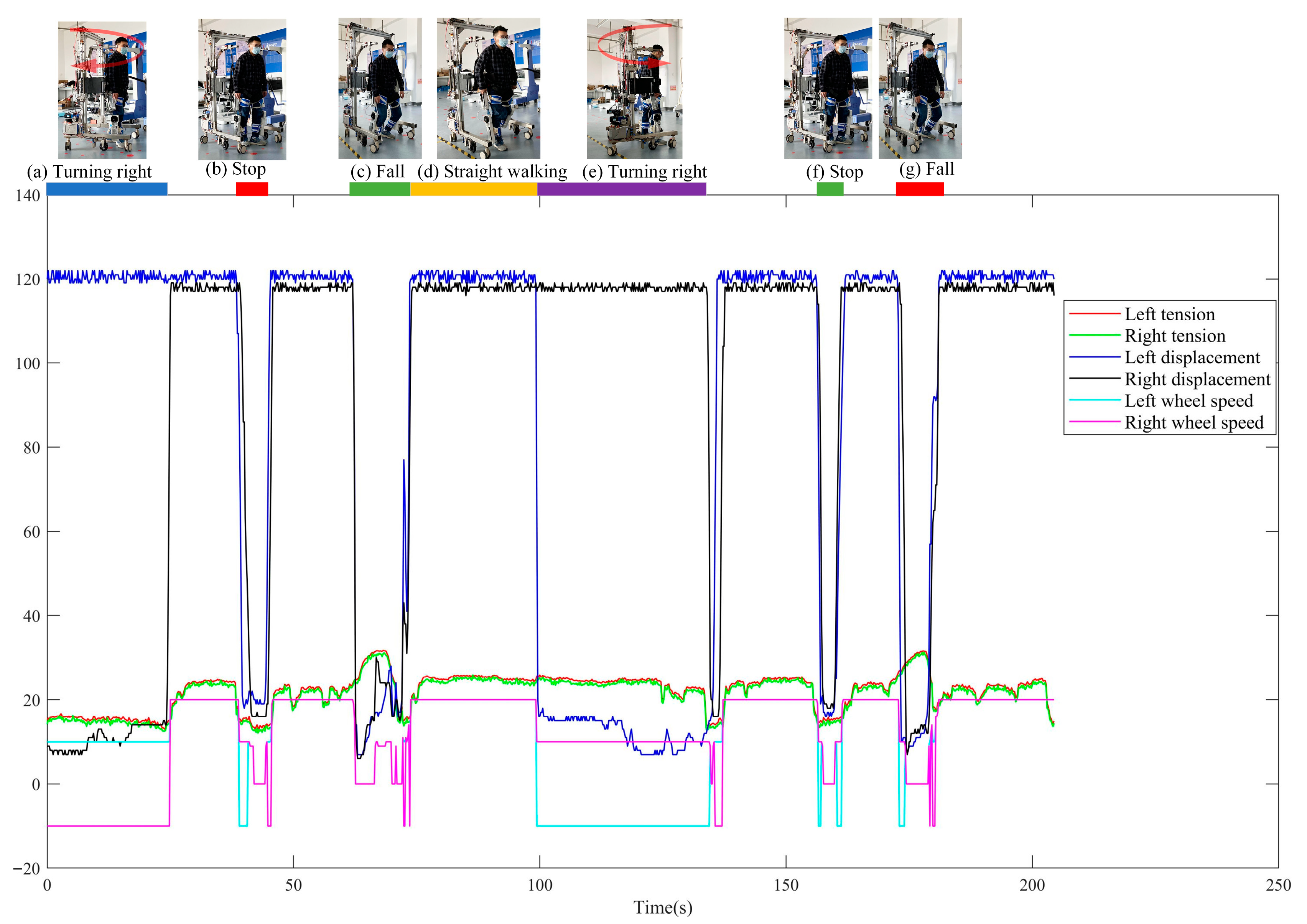
An informed consent was provided to them before the experiment. Figure 2 presents a complete set of training data. During the training process of 200 s, the actions such as left turn, stop, straight ahead and fall are experienced at one time, while each action can be matched with the corresponding sensor information. Note that the fall state described in the text is that the legs are flexed and lose support, and do not fall to the ground, because the weight reduction mechanism can give the body a certain amount of support, as shown in Figure 2c. This is decent for performing feature extraction and calibration.

3. Motion Intent Recognition Model

3.1. Feature Extraction

In order to construct a dataset for the machine learning algorithm to train on, the data of displacement, tension, and wheel speed should be labeled with features. In order to simplify the calibration task, a fast calibration is performed by segmenting the events with displacement, tension and wheel speed data. When the patient walks in the rehabilitation robot, the force sensor can detect the up and down fluctuation of the human body’s center of gravity. When the left and right force sensors’ tension values steeply increase, the human body’s gravity is applied to the force sensor. The human body is judged to be in the falling state, as shown in the orange dotted box of Figure 3. The sudden change of the tension value outside the orange circle is related to the change in the center of gravity of human walking and the walking state, the center of gravity floats up, the tension value decreases, the center of gravity sinks, and the tension increases, but these values are near or less than the set weight loss value, and there is no steep increase over the weight loss value; thus, it does not affect our extraction of the fall features.
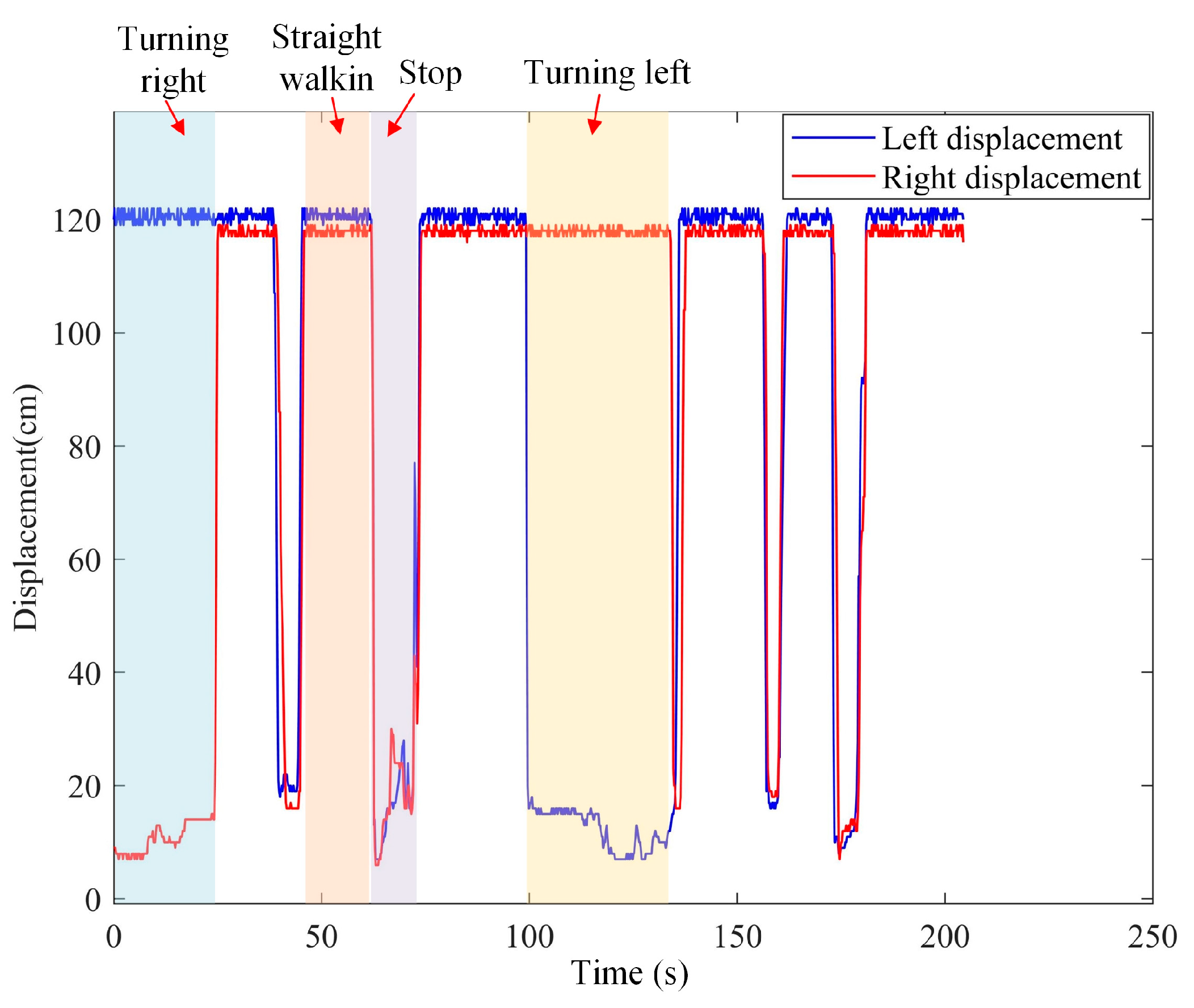
It can be seen from Figure 4 that when the human body walks and turns, the shoulders drive the movement of the displacement sensor above. When the left displacement value is greater than a certain threshold value of the right displacement value, then a right turn is considered, as shown by the blue rectangular box. When the left displacement value is similar to the right displacement value, a straight-line walking is considered, as shown by the orange rectangular box. When the left and right displacement values are less than 3 cm, the body is in a stop state, as shown by the purple rectangular box. When the right displacement value is greater than a certain threshold value of the left displacement value, the human body is in a left-turn state, as shown by the light-yellow rectangle. In addition, when the left and right displacement values are greater than 10 cm, the human body is in a fast-training state. Therefore, the displacement values can reflect the patient’s willingness to train.

3.2. LSTM Intent Classification Model

The RNN is widely used in the classification field. It is very efficient for data with sequential properties and can effectively mine the temporal information in the data [27]. However, RNN produces gradient explosion and disappearance when dealing with long sequence data [28]. The LSTM has a high performance when dealing with long sequence data [29]. Therefore, the deformation structures of RNN, LSTM, and BILSTM are introduced in the sequel.
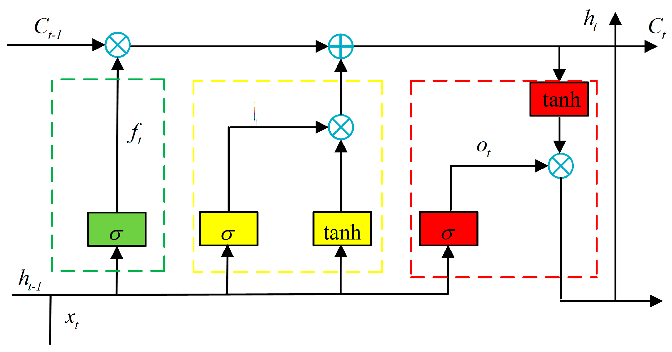
LSTM is a variant of RNN [30], which introduces memory units based on RNN. It has great advantages in processing large amounts of long-term data. In this paper, the more traditional LSTM model is used (cf. Figure 5). The LSTM model consists of three parts, f t is the forgetting gate, i t represents the input gate, and o t denotes the output gate. The role of the forgetting gate f t is to discard the previous information, the input gate i t is to convert the current new information as input. C t is the internal memory cell of the LSTM cell, which is the combined state of the previous cell and the current cell. C ˜ t is the candidate cell state. h t denotes the hidden cell at the current moment. The three gates work together in order to allow the model to control and update the information. σ is the Sigmoid function that decides whether to memorize the information or not, W k   k = f , i , o , c represents the weights of the different gating units, and b k   k = f , i , o , c denotes the bias vectors of the different gating units, and current step input x t . The formula of the LSTM model can be defined as follows:
f t = σ ( W f h t 1 + W f x t + b f ) ,
i t = σ ( W i h t 1 + W i x t + b i ) ,
o t = σ ( W o h t 1 + W o x t + b o ) ,
C ˜ t = tan h ( W C h t 1 + W C x t + b C ) ,
C t = σ ( f t C t 1 + i t C ˜ t ) ,
h t = o t tan h ( C t ) ,
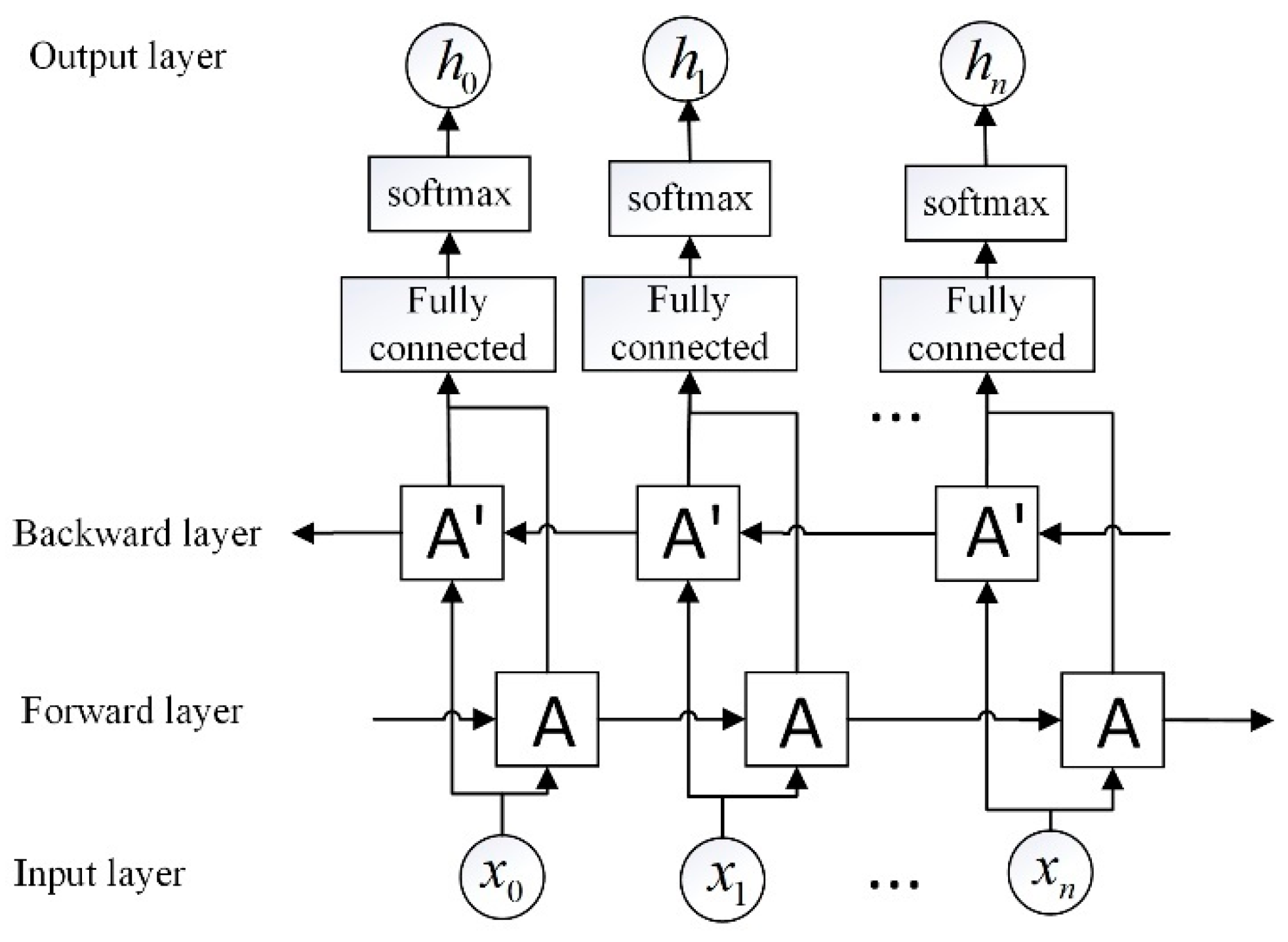
The LSTM network contains five layers: the sequence input layer, LSTM layer, fully connected layer, softmax layer, and output classification layer. The sequence input layer and the LSTM layer are the core of the LSTM network. The role of the input layer is to input the multi-sensing information (displacement, force, rotational speed, and other temporal information) into the LSTM network. The last LSTM module of the LSTM layer is then connected to the Softmax layer and the classification output layer, which finally completes the classification.

3.3. BILSTM Intent Classification Model

BILSTM can use historical information and future contextual information for deep mining of the underlying features through forward and reverse neural network layers, and the output of each BILSTM layer is determined by the two LSTM, which is better than the traditional LSTM network for multi-feature recognition [31]. The structure of BILSTM is shown in Figure 6, where the input layer of the BILSTM network inputs data sequences containing force, displacement, and wheel speed to each LSTM unit, which are recognized by the bidirectional LSTM network, and the human motion feature results with the highest probability are selected in the softmax layer and output to the output layer, where Box A represents a single LSTM unit. x 0 x n denotes a signal source with multi-sensor information. h 0 h n is the class of the output. The model uses a five-layer structure with 100 implicit layers and a learning law of 0.001.

4. Robot Control System

4.1. Control Architecture

The lower limb rehabilitation robot uses a three-layer control architecture, as shown in Figure 7. The upper control layer is used for information acquisition and training, the middle control layer is used for decision making, and the lower control layer is used for execution. In the upper-level control, the sensor information such as displacement, tension, and rotation speed are fed into the BILSTM network that has been trained offline for motion intent classification. In the middle-level control layer, three modes are set: follow training, enhanced training, and assistance training. Follow training represents the exoskeleton driving the human body to move. Enhanced training denotes the human body bearing a certain damping and drives the exoskeleton to move. Assistance training represents the exoskeleton providing a certain amount of assistance to move with the human body. The displacement sensor detects the displacement value in the process of human body movement and can obtain the willingness of human body movement. The displacement and force sensor information are used to classify the human motion events, in order to determine whether the human body is in straight walking, turning left, turning right, falling, or stopping. In the lower-level control, the movement of the exoskeleton and robot drive wheels are controlled according to the human intention events. In addition, the RBF adaptive sliding mode control algorithm is used to follow the trajectories of the hip and knee joints of both legs.
The gait curve of the human body when walking straight, turning left, and turning right is input into the exoskeleton controller. When the BILSTM model outputs the patient’s movement type, the exoskeleton activates the appropriate movement mode, such as output activation, the exoskeleton activates the movement, the output stops, and the exoskeleton stops.

4.2. Dynamical Model

The gait motion of the human lower limb can be divided into two phases: the support phase and swing phase [32]. The swing phase kinetic model contains the exoskeleton kinetic component and the human lower limb exoskeleton interaction force component. This paper uses a general lower limb exoskeleton kinetic model, which does not consider the influence of the human–robot interaction forces in the kinetic modeling. Moreover, the effect of the human–robot interaction force is introduced to improve the developed sagittal plane oscillation phase dynamics model. The lower limb exoskeleton dynamics model can be expressed as:
M ( θ ) θ ¨ + C ( θ ) θ ˙ + G ( θ ) + τ hri = τ ,
where θ is the joint rotation angle, θ ˙ represents the angular velocity of the joint rotation, θ ¨ denotes the angular acceleration of the rotation, M ( θ ) is the inertia matrix, C ( θ ) represents the centrifugal force, G ( θ ) denotes the gravitational force matrix, and τ hri is the introduced human–robot interaction force.
M ( θ ) = I 1 + m 1 d 1 2 + m 2 L 1 2 + m 2 d 2 2 + 2 m 2 L 1 d 2 cos θ 2 m 2 d 2 2 + m 2 L 1 d 2 cos θ 2 m 2 d 2 2 + m 2 L 1 d 2 cos θ 2 I 2 + m 2 d 2 2 ,
C ( θ ) = m 2 L 1 d 2 sin θ 2 2 m 2 L 1 d 2 sin θ 2 m 2 L 1 d 2 sin θ 2 0 ,
G ( θ ) = ( m 1 gd 1 + m 2 gL 1 ) sin θ 1 + m 2 gd 2 sin ( θ 1 + θ 2 ) m 2 gd 2 sin ( θ 1 + θ 2 ) ,
where I 1 is the moment of inertia of the thigh bar, I 2 the moment of inertia of the calf bar, L 1 the length of the thigh bar, L 2 the length of the calf bar, d 1 the distance from the hip joint to the center of mass of the thigh bar, d 2 the knee joint to the calf bar the distance from the center of mass, m 1 the mass of the thigh, and m 2 the mass of the calf bar.

4.3. Controller Design

4.3.1. PID Control

PID controllers are widely used in robot control, and we use PID controllers as a reference to compare the effect of gait tracking. The PID algorithm is as follows:
G ( S ) = k p + k i 1 S + k d S ,
where k p , k i , and k d are the proportional, integral, and differential parameters, respectively.

4.3.2. RBF Adaptive Sliding Mode Control

The gait trajectory tracking error is given by:
e ( t ) = θ ( t ) θ d ( t ) ,
where θ d ( t ) is the gait reference trajectory and θ ( t ) represents the actual joint motion angle fed by the exoskeleton motor encoder. The sliding mode function is then constructed as:
s = c e + e ˙   c > 0 .
RBF neural networks have a higher generalization ability and simpler network structure, which eliminates unnecessary redundant computations [33]. The RBF neural networks are widely used due to their ability to approximate any nonlinear function with an arbitrary accuracy [34].
τ hri is the human–robot interaction force between the lower limb exoskeleton and the human leg, which is not yet directly detectable in the existing sensor systems. In this paper, the RBF neural networks are used to estimate τ hri online, which can compensate for the human–robot interaction force.
h j = exp ( x c j 2 2 b j 2 ) ,
τ hri ( θ ) = W * T h ( θ ) ,
where x = [ e   e ˙ ] T is the input of the network, j represents the j th node of the network hidden layer, h = [ h j ] denotes the output of the Gaussian basis function of the network, and W * is the ideal weight of the network, c is the coordinate vector of the centroid of the Gaussian basis function of the neurons in the hidden layer, and b is the width of the Gaussian basis function of the neurons in the hidden layer. We determine the weights of the RBF network by the gradient descent method, and we define the error metric of the network approximation as:
E ( θ ) = 1 2 τ hri ( θ ) W j ( x c j 2 2 b j 2 ) 2 .
According to the gradient descent method, in order to minimize the error indicator function, the weights are adjusted using the following Equation:
Δ W j ( t ) = η τ hri ( θ ) τ ^ hri ( θ ) h j .
The network output is as follows:
τ ^ hri ( θ ) = W ^ T h ( θ ) ,
where W ^ is the estimated weight of the network.
The trajectory tracking controller is expressed as:
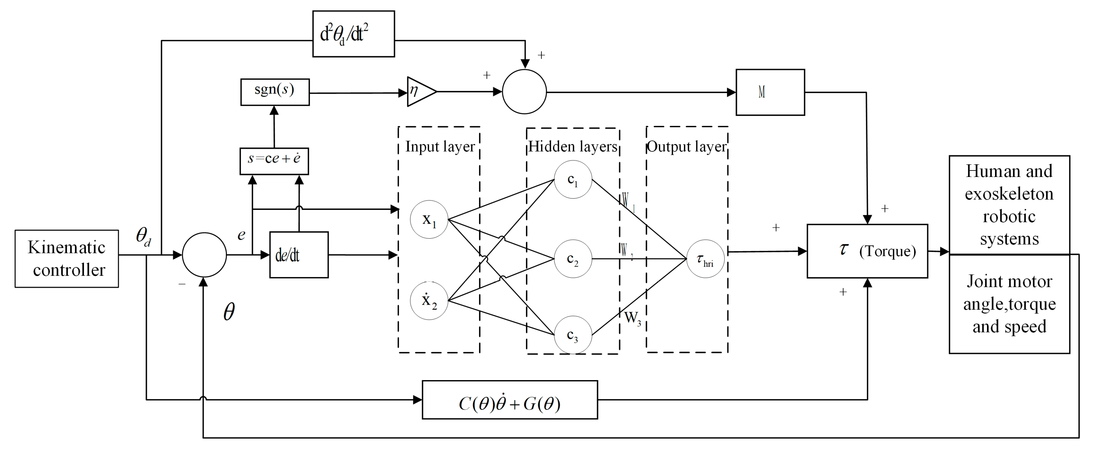
τ = M ( c e + θ ¨ d + η sgn ( s ) ) + C ( θ , θ ˙ ) θ ˙ + G ( θ ) + τ hri .
The Lyapunov function is defined as:
V = 1 2 s 2 + 1 2 γ W ˜ T W ˜ ,
where W ˜ = W ^ W * and γ > 0 . The derivative of the Lyapunov function is given by:
V ˙ = s { c e ˙ + M 1 [ τ τ hri C ( θ , θ ˙ ) θ ˙ G ( θ ) ] θ ¨ d } + 1 γ W ˜ T W ^ ˙ ,
the control law is then substituted into V ˙ .
V ˙ = s [ η sgn ( s ) + ε W ˜ T h ( θ ) ] + 1 γ W ˜ T W ^ ˙ = ε s η s + W ˜ T ( 1 γ W ^ ˙ s h ( θ ) )
by considering η > ε max , the adaptive law is expressed as:
W ^ ˙ = γ s h ( θ ) ,
and therefore: V ˙ = ε s η s 0 . The control system is asymptotically stable, according to the LaSalle invariant set principle.
The robot control system is shown in Figure 8. The input of the system is the preset joint angle curve, while its output of the system is the control torque required by the motor. The input of the RBF neural network is the error of the system and the derivative of the error, while its output is the human–robot interaction force that is estimated online. Using the sliding mode controller combined with the dynamic equation of the lower limb exoskeleton, the torque of each joint of the lower limb is obtained, and the actual torque required by each motor is obtained by adding the human–robot interaction torque and the torque of the dynamic equation. RBF is used to estimate the interaction torque between human and machine and the influence of uncertain factors online. In addition, the adaptive sliding mode control is used to increase the robustness of the control system.

5. Experiments and Results

5.1. Motion Intention Recognition Experiment

The machine learning algorithm was performed in matlab2021a with a computer consisting of an AMD R7 5800H and an NVIDIA GeForce RTX3060 laptop GPU. The experiments included intention classification experiments and gait trajectory tracking experiments. For the intention classification experiment of MLLERR, we collected 6144 sets of training data from six healthy student volunteers (including five male and one female, age 25 ± 4 and weighing 60 ± 10 kg), imported and loaded the data into Matlab, and used the BILSTM, LSTM and GRU (gated recurrent unit) classification models to evaluate the classification accuracy of human behavioral intention. Data from five volunteers were randomly selected as model training data, and data from one volunteer were used as test data.
The average accuracy of the proposed three classification models in lower limb motion intention recognition is presented in Table 2. The average precision is calculated by using the ratio of the number of all correct test samples to the total number of samples. BILSTM achieves 99.61% accuracy in classifying the test data, while GRU and LSTM achieve 95.90% and 96.77%, respectively. In terms of the loss of classification, the time loss of all three classification algorithms is between 0.05 and 0.07 s. The classification accuracy is the most important index pursued under the premise of insignificant classification time loss. In addition, because the control period of the exoskeleton is 10 Hz, the time loss of intention classification does not affect the control of the exoskeleton.
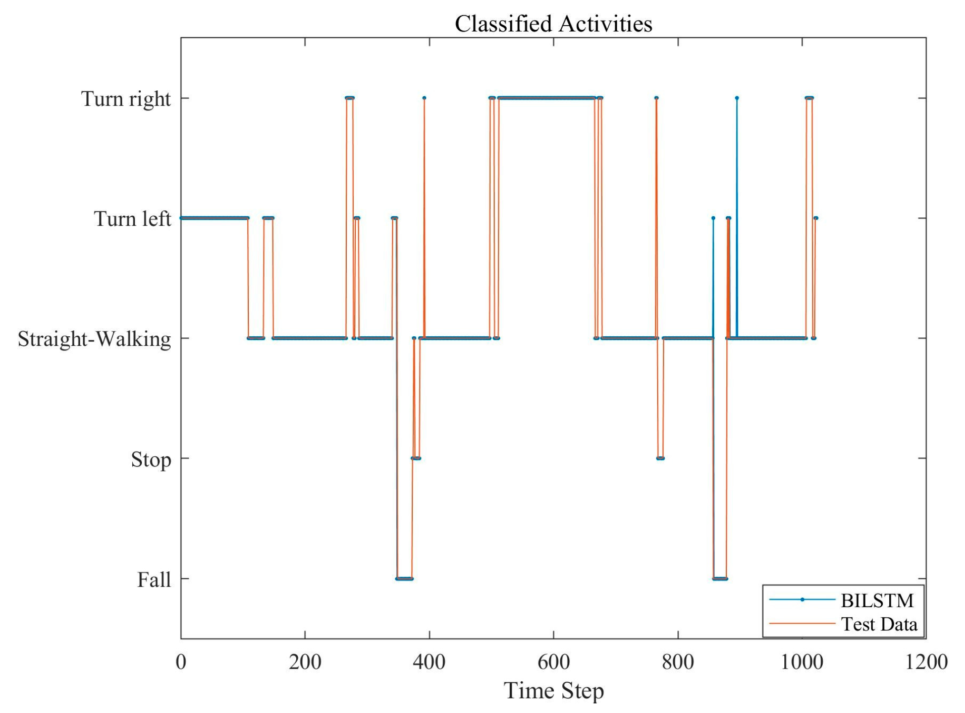
Table 3 presents the classification accuracy of the three classification models for each motion event. It can be seen that the highest classification accuracy for the turning left motion is 100.00% for LSTM, 99.68% for straight walking motion, 100% for turn right motion, 97.83% for fall events, and 100% for BILSTM. The highest classification accuracy for stop events is 100% for BILSTM. The BILSTM classification model outperforms the other two models in terms of recognition accuracy, for all the activities. The classification effect of the BILSTM algorithm on the test data is presented in Figure 9, where the blue line indicates that the BILSTM classifier classifies the test data into different activity events.
Presents the classification accuracy of the three classification models for each motion event. It can be seen that the highest classification accuracy for the turning left motion is 100.00% for LSTM, 99.68% for straight walking motion, 100% for turn right motion, 97.83% for fall events, and 100% for BILSTM. The highest classification accuracy for stop events is 100% for BILSTM. The BILSTM classification model outperforms the other two models in terms of recognition accuracy, for all the activities. The classification effect of the BILSTM algorithm on the test data is presented in Figure 9, where the blue line indicates that the BILSTM classifier classifies the test data into different activity events.

5.2. Tracking Control Experiments

In the simulation experiments, we continuously adjusted the parameters of the PID controller to make the overshoot of the control curve smaller and the rapidity enhanced, and we tuned the parameters of the PID controller to the optimal state with k p = [500 0; 0 500], k d = [50 0; 0 50]. In the RBFNNSAMC algorithm, γ = 490 , η = 0.5 , c i = [ 2 1   0   1   2 ] , and b i = 2 ; the initial value of the network weights is 0.1.
Aiming at the tracking problem of the joint gait trajectory of the lower limb exoskeleton of MLLERR, a simulation experiment of joint gait is designed to determine the parameters of the system, and the control effect of the proposed RBFNNSAMC controller is compared with the PID controller. The exoskeleton drives the human leg to move according to the gait curve, during the walking process of the human wearer robot. The torque information calculated using the RBFNNASMC and PID controller is the input of each joint motor, while the output is the joint angle. The joint feedback angle is collected using the encoder at the joint, in order to compare the tracking effect of the two control algorithms for each joint.
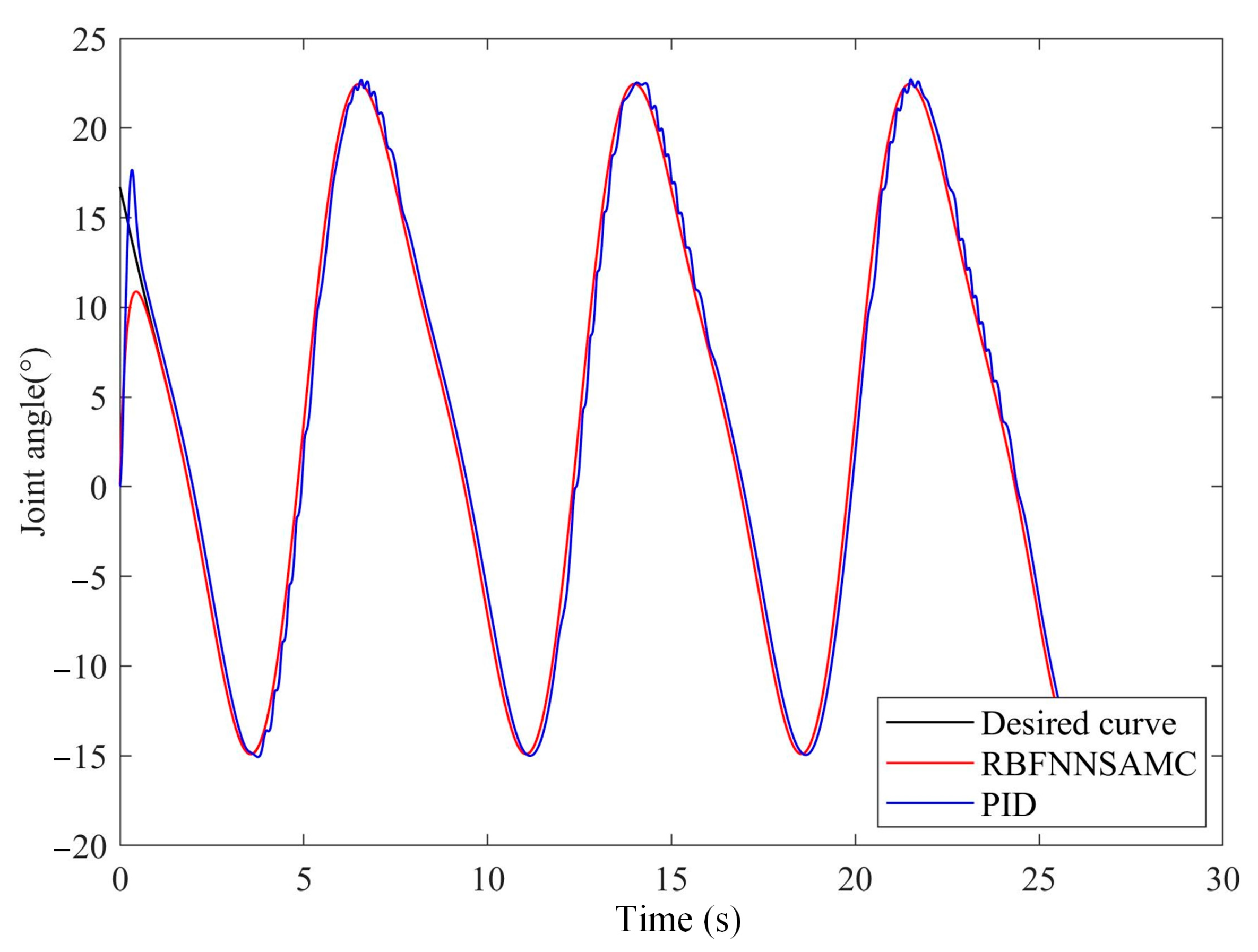
Figure 10 presents the results of the gait trajectory following the hip joint. It can be seen from the blue line that the PID controller shows a large amount of overshoot in the first 1.8 s of the gait start. It then continuously spikes in the remaining gait curve cycles, due to the inability to cope with the external disturbance and thus the motor stalling. In addition, it can be seen from the red line that the RBFNNASMC controller is in converging motion and generates errors in the first 1.2 s. However, it can accurately follow the black reference curve in the remaining gait cycle.
Figure 11 illustrates the results of the gait following control experiment of the knee joint. It can be observed that both the PID controller and the RBFNNASMC controller show a maximum error close to 3° in the first 1.5 s. In the remaining gait cycles, the PID controller shows a significant lag in the following process, and the error does not achieve a perfect convergence, while the RBFNNASMC controller reaches a sliding mode and the error is retained. The RBFNNASMC controller achieves a sliding mode with the error constantly converging to zero. Therefore, it achieves the purpose of tracking the gait. In summary, the analysis of Figure 10 and Figure 11 verifies the efficiency of the proposed RBF neural network adaptive sliding mode controller for curve tracking.
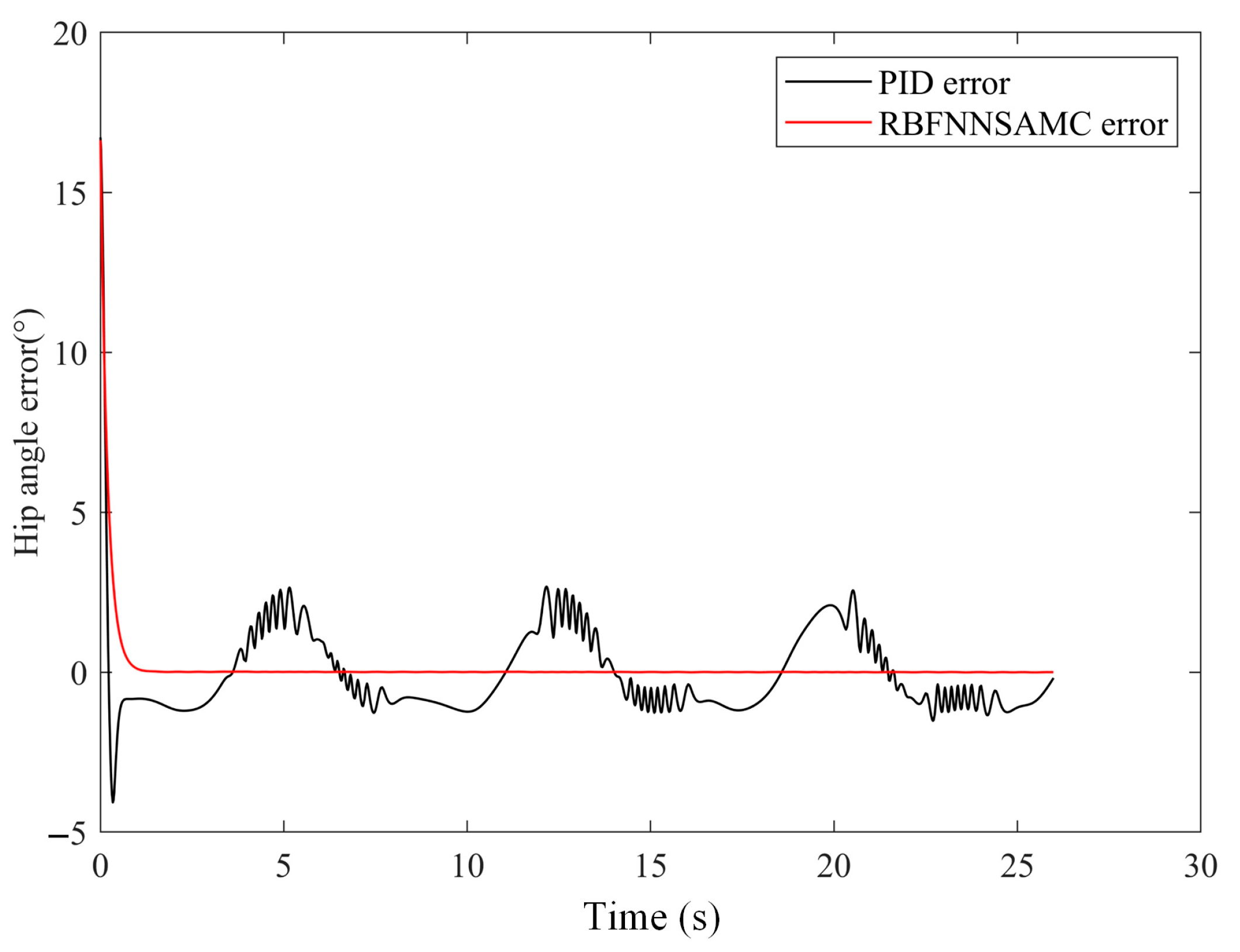
It can be seen from the error curves of the hip and knee joints in Figure 12 and Figure 13 that the error curve of PID presents a large spike-like fluctuation, and the trend of error fluctuation is periodic. This indicates that the PID algorithm cannot adaptively cancel the influence of human–robot interaction force and disturbance, and this kind of high-frequency jitter is unbearable for the motor.
Error analysis is performed on the gait curves of the two algorithms, as shown in Table 4. The performance of the PID controller and RBFNNSAMC controller is analyzed from three aspects: maximum error, average error, and standard deviation. The analysis of the maximum error reflects the amount of error in the starting stage of the motor. Both controllers show a large overshoot in the hip and knee joints. The control effects are similar, and the control error of RBFNNSAMC is slightly smaller. It can be deduced from the analysis of the average error and standard deviation, which reflects the overall error in the whole gait cycle, that the RBFNNSAM controller has a clearly superior performance. The average errors of the hip and knee joints are respectively 0.197° and 0.037°, while the average errors of the PID controller at the hip and knee joints are 1.405° and 1.822°, respectively. From the standard deviation point of view, the control curve errors of the PID controller are also larger than those of the RBFNNSAM controller. In summary, the PID controller is clearly not suitable for time-varying systems, and the RBFNNSAM controller can make adaptive adjustments to the disturbance, thereby reducing the error.
The experiments in Section 5.1 verified the effectiveness of our proposed algorithm for the recognition of human motion features. The recognition of human movements such as turning, walking, stopping, and falling is achieved, which allows patients to walk more naturally according to their wishes and achieve better human–robot coordination. In Section 5.2, the gait tracking experiment enables the exoskeleton to drive the human leg movement more precisely, so that the patient can restore the leg muscle strength and enhance the walking ability.

6. Discussion

As can be seen in Table 1 and Table 2, the results of the proposed BILSTM network in this paper for the recognition of the motion intention of human lower limb walking using multi-sensor information show that the BILSTM algorithm has advantages in multi-feature and repetitive motion. The BILSTM algorithm can be promising for human gait, posture and other aspects of recognition in the future. However, it also has some limitations. Firstly, the training of data such as force, displacement and wheel speed from the experiments takes a lot of time. Although our training data sample is small, only six volunteers’ training data can support the above experimental results, because the force, displacement, and wheel speed sensor data are periodic and repetitive in the rehabilitation training process, and each sensor only cycles through a specific range, and the data of six volunteers have fully covered these ranges. Therefore, the above experimental results are convincing. In the future, we will optimize the hyperparameters of the model online through advanced optimization algorithms to improve the deficiencies of the BILSTM model in terms of real time and adaptiveness.
In the gait trajectory tracking experiments, it can be seen from Table 3 that the errors of the RBFNNSAMC algorithm are smaller than those of the PID algorithm in the results of maximum error, average error, and standard deviation. This proves that our proposed RBFNNSAMC algorithm has some advantages over the PID algorithm in gait tracking. In the future, we will enrich our sensor information system by adding human–robot interaction sensors such as force sensors or EMG sensors. We will use these sensors to directly measure human movement data to achieve a more flexible human–robot interaction effect.
Robot-assisted therapy is already widely used in the field of rehabilitation. Robotic therapy is no longer concerned with only the medical field, but also, e.g., special education and other fields [35,36]. These are also the direction of our research in the future.

7. Conclusions

In this paper, we conduct rehabilitation training research on both human motion intention recognition and gait trajectory tracking of MLLERR, and we propose a BILSTM classifier to recognize five activity behaviors of human lower limbs. Through the comparison of experimental data, BILSTM shows superior performance in terms of average error and accuracy of recognition of each activity event compared with traditional machine learning classifiers, and the real-time performance meets the requirements of the control system. In the lower limb exoskeleton control system, we designed an RBF adaptive sliding mode controller to estimate the human–robot interaction forces and perturbations online through RBF networks, and we performed stability proof of the human–robot interaction dynamics system using Lyapunov theory. In the simulation experiments, we introduced perturbations to the hip and knee joints, and the simulation results showed that the position tracking effect of the RBF adaptive sliding mode controller was better than that of the PID controller. Moreover, the bucket vibration of the sliding mode control is suppressed by the compensation of the disturbance through the RBF network. However, we still have to continue to improve the real-time nature of machine learning models and control systems, which will enable more coordinated human–robot interaction. In future work, we will focus on human wearing and walking sensations and optimize the lower limb exoskeleton control system using gait planning and flexible drive algorithms.

Author Contributions

Methodology, P.Z. (Pengfei Zhang) and P.Z. (Peng Zhao); software, X.G.; validation, P.Z. (Pengfei Zhang) and P.Z. (Peng Zhao); formal analysis, M.M.; investigation, analysis of data, X.G.; performed the experiments, P.Z. (Pengfei Zhang) and X.G.; writing—original draft preparation, P.Z. (Pengfei Zhang). All authors have read and agreed to the published version of the manuscript.

Funding

This research was supported by the Province Key R&D Program of Guangxi (AB22035006) and by the National Key R&D Program of China (grant no. 2020YFC2008503).

Data Availability Statement

Not applicable.

Conflicts of Interest

The authors declare no conflict of interest.

References

  1. Dong, F.; Li, H.; Feng, Y. Mechanism Design and Performance Analysis of a Sitting/Lying Lower Limb Rehabilitation Robot. Machines 2022, 10, 674. [Google Scholar] [CrossRef]
  2. Paraskevas, K.I. Prevention and Treatment of Strokes Associated with Carotid Artery Stenosis: A Research Priority. Ann. Transl. Med. 2020, 8, 1260. [Google Scholar] [CrossRef] [PubMed]
  3. Zhang, X.; Yue, Z.; Wang, J. Robotics in Lower-Limb Rehabilitation after Stroke. Behav. Neurol. 2017, 2017, 3731802. [Google Scholar] [CrossRef] [PubMed] [Green Version]
  4. Yang, T.; Gao, X. Adaptive Neural Sliding-Mode Controller for Alternative Control Strategies in Lower Limb Rehabilitation. IEEE Trans. Neural Syst. Rehabil. Eng. 2020, 28, 238–247. [Google Scholar] [CrossRef]
  5. Díaz, I.; Gil, J.J.; Sánchez, E. Lower-Limb Robotic Rehabilitation: Literature Review and Challenges. J. Robot. 2011, 2011, 759764. [Google Scholar] [CrossRef] [Green Version]
  6. Li, K.; Zhang, J.; Wang, L.; Zhang, M.; Li, J.; Bao, S. A Review of the Key Technologies for SEMG-Based Human-Robot Interaction Systems. Biomed. Signal Process. Control 2020, 62, 102074. [Google Scholar] [CrossRef]
  7. Bulea, T.C.; Kilicarslan, A.; Ozdemir, R.; Paloski, W.H.; Contreras-Vidal, J.L. Simultaneous Scalp Electroencephalography (EEG), Electromyography (EMG), and Whole-Body Segmental Inertial Recording for Multi-Modal Neural Decoding. J. Vis. Exp. 2013, 77, 50602. [Google Scholar] [CrossRef] [Green Version]
  8. Iqbal, N.; Khan, T.; Khan, M.; Hussain, T.; Hameed, T.; Bukhari, S.A.C. Neuromechanical Signal-Based Parallel and Scalable Model for Lower Limb Movement Recognition. IEEE Sens. J. 2021, 21, 16213–16221. [Google Scholar] [CrossRef]
  9. Zhang, K.; Zhang, W.; Xiao, W.; Liu, H.; De Silva, C.W.; Fu, C. Sequential Decision Fusion for Environmental Classification in Assistive Walking. IEEE Trans. Neural Syst. Rehabil. Eng. 2019, 27, 1780–1790. [Google Scholar] [CrossRef] [Green Version]
  10. Martinez-Hernandez, U.; Mahmood, I.; Dehghani-Sanij, A.A. Simultaneous Bayesian Recognition of Locomotion and Gait Phases With Wearable Sensors. IEEE Sens. J. 2018, 18, 1282–1290. [Google Scholar] [CrossRef]
  11. Ding, S.; Ouyang, X.; Liu, T.; Li, Z.; Yang, H. Gait Event Detection of a Lower Extremity Exoskeleton Robot by an Intelligent IMU. IEEE Sens. J. 2018, 18, 9728–9735. [Google Scholar] [CrossRef]
  12. Chinimilli, P.T.; Redkar, S.; Sugar, T. A Two-Dimensional Feature Space-Based Approach for Human Locomotion Recognition. IEEE Sens. J. 2019, 19, 4271–4282. [Google Scholar] [CrossRef]
  13. Gao, X.; Yang, T.; Peng, J. Logic-Enhanced Adaptive Network-Based Fuzzy Classifier for Fall Recognition in Rehabilitation. IEEE Access 2020, 8, 57105–57113. [Google Scholar] [CrossRef]
  14. Kanjo, E.; Younis, E.M.G.; Ang, C.S. Deep Learning Analysis of Mobile Physiological, Environmental and Location Sensor Data for Emotion Detection. Inf. Fusion 2019, 49, 46–56. [Google Scholar] [CrossRef]
  15. Pastor, F.; Garcia-Gonzalez, J.; Gandarias, J.M.; Medina, D.; Closas, P.; Garcia-Cerezo, A.J.; Gomez-de-Gabriel, J.M. Bayesian and Neural Inference on LSTM-Based Object Recognition From Tactile and Kinesthetic Information. IEEE Robot. Autom. Lett. 2021, 6, 231–238. [Google Scholar] [CrossRef]
  16. Xing, Y.; Lv, C. Dynamic State Estimation for the Advanced Brake System of Electric Vehicles by Using Deep Recurrent Neural Networks. IEEE Trans. Ind. Electron. 2020, 67, 9536–9547. [Google Scholar] [CrossRef]
  17. Siami-Namini, S.; Tavakoli, N.; Siami Namin, A. A Comparison of ARIMA and LSTM in Forecasting Time Series. In Proceedings of the 2018 17th IEEE International Conference on Machine Learning and Applications (ICMLA), Orlando, FL, USA, 17–20 December 2018; pp. 1394–1401. [Google Scholar]
  18. Qiu, L.; Chen, Y.; Jia, H.; Zhang, Z. Query Intent Recognition Based on Multi-Class Features. IEEE Access 2018, 6, 52195–52204. [Google Scholar] [CrossRef]
  19. Cho, K.; van Merrienboer, B.; Gulcehre, C.; Bahdanau, D.; Bougares, F.; Schwenk, H.; Bengio, Y. Learning Phrase Representations Using RNN Encoder-Decoder for Statistical Machine Translation. arXiv 2014, arXiv:1406.1078. [Google Scholar]
  20. Wu, Q.; Chen, Y. Development of an Intention-Based Adaptive Neural Cooperative Control Strategy for Upper-Limb Robotic Rehabilitation. IEEE Robot. Autom. Lett. 2021, 6, 335–342. [Google Scholar] [CrossRef]
  21. Mehr, J.K.; Sharifi, M.; Mushahwar, V.K.; Tavakoli, M. Intelligent Locomotion Planning With Enhanced Postural Stability for Lower-Limb Exoskeletons. IEEE Robot. Autom. Lett. 2021, 6, 7588–7595. [Google Scholar] [CrossRef]
  22. Mohd Khairuddin, I.; Sidek, S.N.; Abdul Majeed, A.P.P.; Mohd Razman, M.A.; Ahmad Puzi, A.; Md Yusof, H. The Classification of Movement Intention through Machine Learning Models: The Identification of Significant Time-Domain EMG Features. PeerJ Comput. Sci. 2021, 7, e379. [Google Scholar] [CrossRef] [PubMed]
  23. Shi, Q.; Ying, W.; Lv, L.; Xie, J. Deep Reinforcement Learning-Based Attitude Motion Control for Humanoid Robots with Stability Constraints. Ind. Robot Int. J. Robot. Res. Appl. 2020, 47, 335–347. [Google Scholar] [CrossRef]
  24. Al-Shuka, H.F.N.; Rahman, M.H.; Leonhardt, S.; Ciobanu, I.; Berteanu, M. Biomechanics, Actuation, and Multi-Level Control Strategies of Power-Augmentation Lower Extremity Exoskeletons: An Overview. Int. J. Dyn. Control 2019, 7, 1462–1488. [Google Scholar] [CrossRef]
  25. Vantilt, J.; Giraddi, C.; Aertbelien, E.; De Groote, F.; De Schutter, J. Estimating Contact Forces and Moments for Walking Robots and Exoskeletons Using Complementary Energy Methods. IEEE Robot. Autom. Lett. 2018, 3, 3410–3417. [Google Scholar] [CrossRef]
  26. Nguyen, T.T.; Warner, H.; La, H.; Mohammadi, H.; Simon, D.; Richter, H. State Estimation For An Agonistic-Antagonistic Muscle System. Asian J. Control 2019, 21, 354–363. [Google Scholar] [CrossRef] [Green Version]
  27. Wang, S.; Cao, J.; Yu, P.S. Deep Learning for Spatio-Temporal Data Mining: A Survey. IEEE Trans. Knowl. Data Eng. 2022, 34, 3681–3700. [Google Scholar] [CrossRef]
  28. Li, M.; Wang, Y.; Wang, Z.; Zheng, H. A Deep Learning Method Based on an Attention Mechanism for Wireless Network Traffic Prediction. Ad Hoc Netw. 2020, 107, 102258. [Google Scholar] [CrossRef]
  29. Xiang, Z.; Yan, J.; Demir, I. A Rainfall-Runoff Model With LSTM-Based Sequence-to-Sequence Learning. Water Resour. Res. 2020, 56, e2019WR025326. [Google Scholar] [CrossRef]
  30. Yao, S.; Luo, L.; Peng, H. High-Frequency Stock Trend Forecast Using LSTM Model. In Proceedings of the 2018 13th International Conference on Computer Science & Education (ICCSE), Colombo, Sri Lanka, 8–11 August 2018. [Google Scholar]
  31. Peng, T.; Zhang, C.; Zhou, J.; Nazir, M.S. An Integrated Framework of Bi-Directional Long-Short Term Memory (BiLSTM) Based on Sine Cosine Algorithm for Hourly Solar Radiation Forecasting. Energy 2021, 221, 119887. [Google Scholar] [CrossRef]
  32. Chen, C.-F.; Du, Z.-J.; He, L.; Shi, Y.-J.; Wang, J.-Q.; Xu, G.-Q.; Zhang, Y.; Wu, D.-M.; Dong, W. Development and Hybrid Control of an Electrically Actuated Lower Limb Exoskeleton for Motion Assistance. IEEE Access 2019, 7, 169107–169122. [Google Scholar] [CrossRef]
  33. Pérez-Sánchez, B.; Fontenla-Romero, O.; Guijarro-Berdiñas, B. A Review of Adaptive Online Learning for Artificial Neural Networks. Artif. Intell. Rev. 2018, 49, 281–299. [Google Scholar] [CrossRef]
  34. Zhang, Y.; Chen, B.; Pan, G.; Zhao, Y. A Novel Hybrid Model Based on VMD-WT and PCA-BP-RBF Neural Network for Short-Term Wind Speed Forecasting. Energy Convers. Manag. 2019, 195, 180–197. [Google Scholar] [CrossRef]
  35. Vostrý, M.; Lanková, B.; Zilcher, L.; Jelinková, J. The Effect of Individual Combination Therapy on Children with Motor Deficits from the Perspective of Comprehensive Rehabilitation. Appl. Sci. 2022, 12, 4270. [Google Scholar] [CrossRef]
  36. Bartík, P.; Vostrý, M.; Hudáková, Z.; Šagát, P.; Lesňáková, A.; Dukát, A. The Effect of Early Applied Robot-Assisted Physiotherapy on Functional Independence Measure Score in Post-Myocardial Infarction Patients. Healthcare 2022, 10, 937. [Google Scholar] [CrossRef]
Figure 1. Structure and hardware control platform of lower limb exoskeleton rehabilitation robot.
Machines 10 01125 g001aMachines 10 01125 g001b
Figure 2. Exercise events in walking training: (a) turning right, (b) stop, (c) fall, (d) straight walking, (e) turning left, (f) stop, (g) fall. The red and green lines represent the tension values of the left and right weight loss arms, respectively. The blue and black lines represent the left and right displacements, respectively.
Machines 10 01125 g002
Figure 3. The fall event calibration. The abrupt increase in the tension value indicates that the body is in a fall state.
Machines 10 01125 g003
Figure 4. Turning characteristics.
Machines 10 01125 g004
Figure 5. The LSTM unit.
Machines 10 01125 g005
Figure 6. The net structure of the BILSTM network.
Machines 10 01125 g006
Figure 7. Control architecture.
Machines 10 01125 g007
Figure 8. RBF adaptive sliding mode control block diagram for lower limb exoskeleton robot.
Machines 10 01125 g008
Figure 9. Classification results. The vertical axis represents the actions and events of the human body during training, while each action refers to the corresponding data segment.
Machines 10 01125 g009
Figure 10. Results of the gait trajectory following the hip joint.
Machines 10 01125 g010
Figure 11. Results of the gait trajectory following the knee joint.
Machines 10 01125 g011
Figure 12. The hip gait error curve.
Machines 10 01125 g012
Figure 13. The knee gait error curve.
Machines 10 01125 g013
Table 1. Mechanical motion properties of the lower limb exoskeleton.
Hip JointKnee Joint
Rated torque65 Nm45 Nm
Rotational Speed20 rpm25 rpm
Range of motionPE 1: −10–25°PE: 0–65°
1 FE: flexion/extension.
Table 2. Accuracy and elapsed time of the three algorithms for human activity events.
GRULSTMBILSTM
Accuracy95.90%96.77%99.61%
Elapsed time0.053 s0.059 s0.066 s
Table 3. Accuracy of the three algorithms for human activity events.
GRULSTMBILSTM
Turn left99.30%100.00%99.30%
Straight walking99.36%99.52%99.68%
Turn right83.33%86.46%100%
Fall93.48%93.48%97.83%
Stop84.21%94.74%100%
Table 4. Accuracy and elapsed time of the three algorithms for human activity events.
Maximum ErrorAverage ErrorStandard Deviation
HipKneeHipKneeHipKnee
PID16.718°4.556°1.405°1.822°2.235°1.497°
RBFNNSAMC16.628°2.996°0.197°0.037°1.486°0.269°
Publisher’s Note: MDPI stays neutral with regard to jurisdictional claims in published maps and institutional affiliations.