Article

Design and Performance Investigation of a Vehicle Drive System with a 12/10 Flux-Switching Permanent Magnet Motor

1
Key Laboratory of High Performance Manufacturing for Aero Engine (MIIT), Northwestern Polytechnical University, Xi’an 710072, China
2
Engineering Research Center of Expressway Construction & Maintenance Equipment and Technology of MOE, Chang’an University, Xi’an 710061, China
*
Author to whom correspondence should be addressed.
Machines 2022, 10(12), 1216; https://doi.org/10.3390/machines10121216
Submission received: 21 November 2022 / Revised: 10 December 2022 / Accepted: 12 December 2022 / Published: 14 December 2022

Abstract

:
The performance of a drive system with a flux-switching permanent magnet (FSPM) motor was studied through tests on a commercial electric vehicle (CEV). A practical design and an optimization method for the FSPM motor were proposed for a light-duty CEV. The initial dimensions of the motor were calculated by theoretical equations referring to a permanent magnet synchronous motor. Then, optimization was conducted through a response surface methodology (RSM) and a genetic algorithm (GA) based on three-dimensional finite element analysis (3D-FEA). With the optimized parameters, a prototype of the FSPM drive system was manufactured and assembled into an actual CEV. The performance of the CEV was investigated on an automobile test platform. The experimental results show that the FSPM drive system could drive the CEV properly. The high-efficiency running time of the FSPM motor accounted for 84% of the total time tested, which shows great potential for practical application in CEVs. However, the experimental results also show that the FSPM motor faced problems of large speed deviation and high-temperature rise during the driving cycle test, which should be fully addressed for practical applications.

1. Introduction

With the rapid development of the automotive industry, energy consumption and environmental crisis have become global challenges. New energy vehicles and their related key technologies represent promising approaches for solving these problems. At present, the new energy vehicles mainly consist of hybrid electric vehicles (HEVs) [1,2,3], pure electric vehicles (PEVs) [4], and fuel cell vehicles (FCVs) [5]. PEVs are considered to represent the major field in which there will be rapid developments in the near future because PEVs have outstanding advantages, such as zero emissions during driving, high efficiency, low noise, and a simple mechanical structure. The drive system is one of the critical technologies in PEVs. The drivetrain, including the electric motor and transmission structure, significantly affects the dynamic performance and energy efficiency of PEVs. Therefore, many researchers are attracted to studying and developing various motor systems for PEV application. In previous studies, various motor systems have been widely studied, including induction motors [6,7,8,9], permanent magnet synchronous motors (PMSMs) [10,11,12,13,14], brushless DC motors [15], special structure motors [16,17,18], and switched reluctance motors [11,19,20]. Previous studies have shown that PMSMs exhibit excellent performance, including high power density, ample traction torque, low torque ripple, and good controllability [13,14]. However, PMSMs still need to be improved in many areas for practical application in PEVs, such as robustness during violent working conditions, efficiency with large operation loads, and performance in the low-speed range [11].
Flux switching permanent magnet (FSPM) motors, as a new type of PMSM, are gaining interest from researchers because of the simple and rugged structure, with both the armature windings and permanent magnets on the stator [21,22]. Furthermore, the characteristics of FSPM motors, such as sinusoidal back-electromotive force (EMF), high torque density, and easy thermal management, are appropriate for application in PEVs [23,24]. An FSPM motor, as a competitive candidate for the next generation of drive systems, shows great potential in the PEV field. However, very little work on the performance investigation of FSPMs is available in a real PEV. The present study focused on the optimal design and dynamic performance investigation of an FSPM motor in a real commercial electric vehicle (CEV) [25,26,27]. A CEV is a type of PEV that mainly carries commercial goods. It has shown great sales potential in the Chinese automobile market.
In this paper, a drive system with a 12/10-pole three-phase FSPM motor is designed and studied for practical application in a real CEV. According to the drive requirements of the CEV, the physical dimensions and electromagnetic parameters of an FSPM motor are calculated and optimized by theoretical equations regarding the permanent magnet synchronous motor and finite element analysis (FEA). An optimization method, which combines a response surface methodology (RSM) and a genetic algorithm (GA), is employed in this work. Finally, a prototype of an FSPM motor is manufactured and assembled into a CEV. Performance investigation was carried out on a test bench of electric vehicles. The motor operating condition, efficiency, and temperature rise were investigated and discussed regarding the latest China automotive test standard GB/T 38146.1-2019. The results of this work help to study the performance of an FSPM motor in the application of commercial electric vehicles (CEV). The study results of an FSPM driving system in a CEV may be useful for the practical application of FSPM motors, which is the significant contribution of this work to the application of an FSPM motor in the PEV field.

2. Design of the FSPM Drive System

2.1. Fundamental Structure

A drivetrain with an FSPM motor was designed for a light-duty CEV. In order to simplify the structure, the gearbox and clutch were eliminated from the drivetrain. The drive mechanism is shown in Figure 1. Through a bevel gear reducer, the FSPM motor connects to the differential mechanism to drive the two driver shafts and wheels. Compared with traditional rear-drive, the present drive mechanism is more compact and balanced. Without space constraints, the boundary dimension of the motor and the auxiliary cooling system can be designed freely. Referring to the drive requirement of a type of CEV, which is developed by a local automobile manufacturer, the technical parameters of the drivetrain are determined, as shown in Table 1.

2.2. FSPM Motor

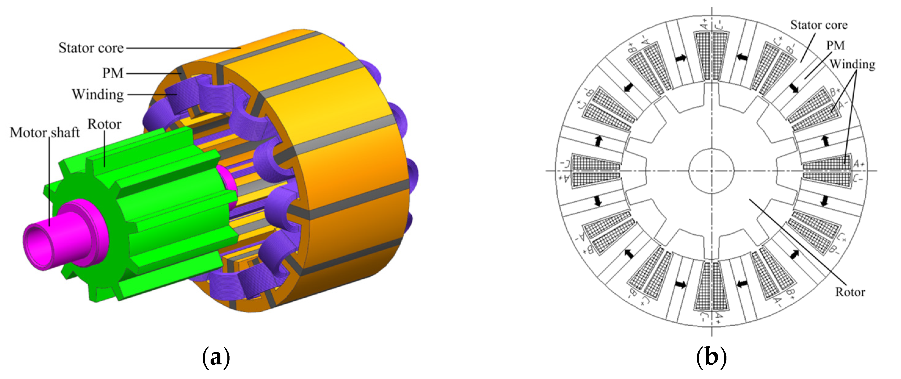
The design of the drive motor is the critical process in the drive system. A 3-phase, 12-stator-tooth, 10-rotor-pole FSPM motor was used in this study; its topology is shown in Figure 2. The rotor structure is just like a switched reluctance motor, so it exhibits great robustness. The permanent magnets and coils are placed in the stator and can be easily cooled. Therefore, the FSPM can be designed with a higher power density and larger field-weakening capability based on the forced cooling method [26].
According to the technical parameters in Table 1, the major dimensions of the FSPM motor can be calculated theoretically. The rated power of the motor can be expressed as [28,29]:
P o e = T e ω m e = m N k E 10 I e
where ω m e is the rated angular speed, m is the phase number, N k is the number of turns per phase, E 10 is the amplitude of no-load electromotive force per turn at the rated speed, and I e is the phase current. E 10 can be calculated as [28]
E 10 = p r ω m e ϕ p e a k
where p r is the number of rotor poles, and ϕ p e a k is the maximum flux linking per turn; it can be calculated as follows [28,29]:
ϕ p e a k = B t π D s i p s c s L a
where B t is the magnetic flux density of stator core, D s i is the inner diameter of stator core, P s is the number of stator poles, c s is the coefficient of tooth width, and L a is the axial length of the stator.
The input current of each concentrated winding can be expressed as the ampere-turns wound around each stator pole.
N k I k = 1 2 J K c u 1 A s l o t = 1 2 J K c u 1 4 1 2 b s l o t + π D s o 2 h y s p s 2 b t s 2 b p m D s o D s i 2 h y s 2
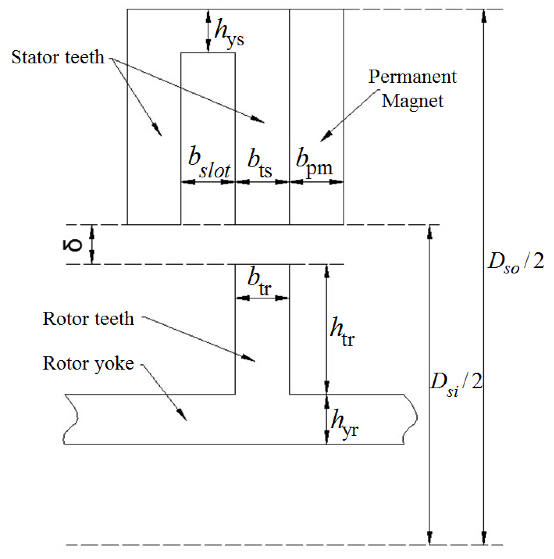
where J is the current density, K c u 1 is the cooper fill factor, A s l o t is the area per slot, b s l o t , b t s , b p m , and h y s are the slot open width, tooth width, permanent magnet width, and yoke height of each stator pole, respectively. D s i is the outer diameter of the stator core.
The dimensional parameters of the FSPM motor are shown in Figure 3. To balance the requirement of magnetic and electrical loadings, the dimensions of the stator pole can be initially set as [28,29]:
b s l o t = b t s = b t r = b p m = h y s = h y r = π K s i o D s o 4 p s
and the height of rotor tooth is initially set as [29]:
h t r = 1 8 ( D s i 2 δ ) = 1 8 ( K s i o D s o 2 δ )
where δ is the air gap length, and K s i o is the split ratio of the stator core.
The selection of the coefficients and factors refers to the literature and practical experience [22,30,31]. Specifically, B t is determined by the limitation of the electromagnetic load and is selected as 2.0 T. J is determined by the performance of the enameled wire and is selected as 5 × 10⁶ A/m2. K c u 1 , K s i o , and δ are determined by experience in the motor-making process and are selected as 0.65, 0.6, and 1.2 mm, respectively. Through the above theoretical equations, the initial parameters of the FSPM motor can be determined, as shown in Table 2.

3. Optimization Method of the FSPM Motor

3.1. Optimization Process

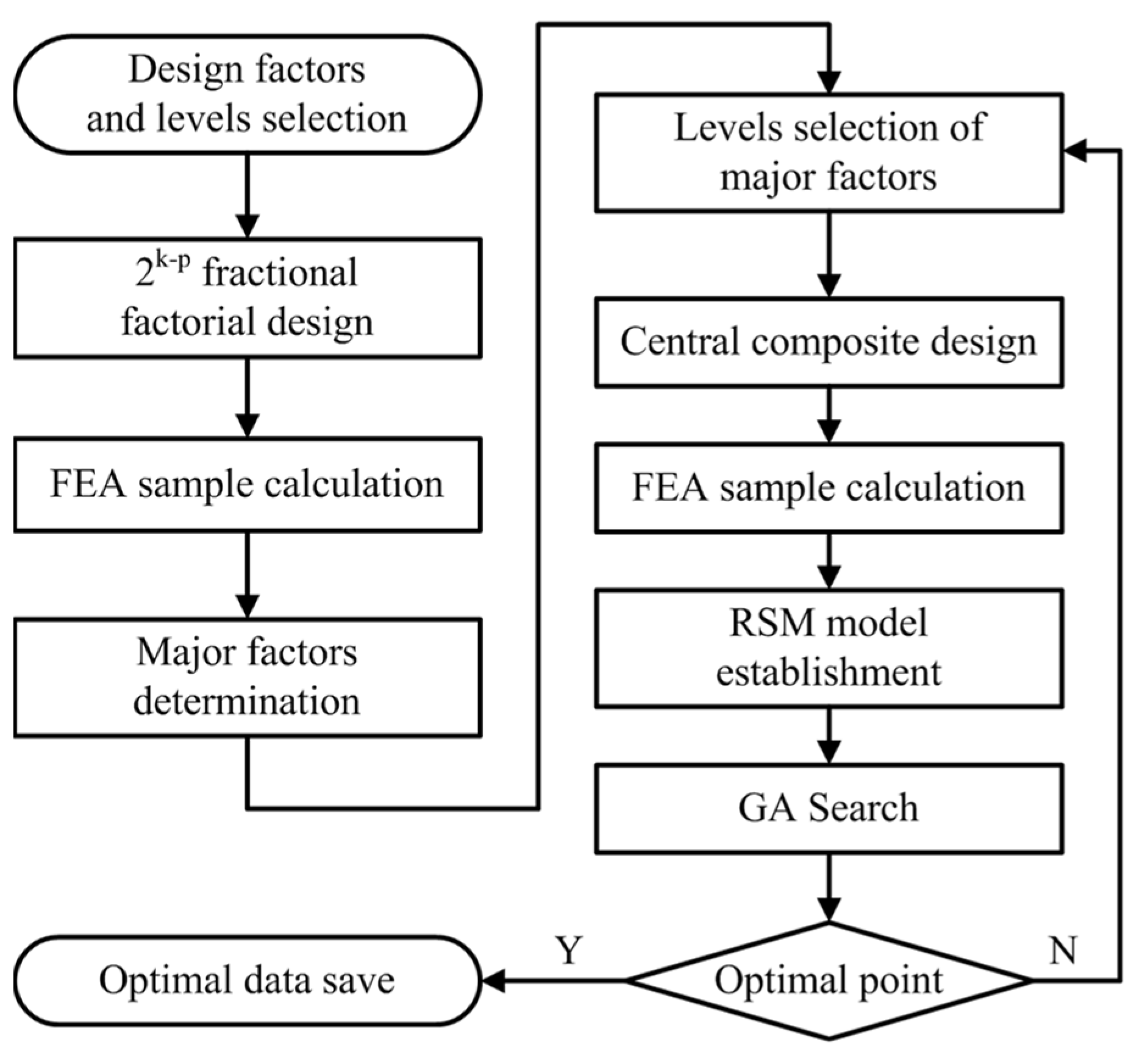
With the initial calculated parameters, a 3D-FEA based on ANSOFT MAXWELL software was employed to analyze the electromagnetic performance of the FSPM motor. The switching magnetic field exhibits nonlinear flux leakage and saturation in the flux-switching topology [21,22], which significantly affects the output performance of the FSPM motor. On the other hand, considering the growing price of rare earth permanent magnets (PMs), the optimal amount of PM becomes an important factor for the cost control of an FSPM motor. Therefore, the dimensions of the FSPM motor were optimized by response surface methodology (RSM) and a genetic algorithm (GA) based on FEA. RSM was used to establish the relationship between the input factors and output responses through the statistical fitting method. In this work, the dimensions of the FSPM motor are the input factors, output torque Tout, and torque ripple Trip, and the ratio of the output torque-to-PM mass Tout/Qpm represents the output responses. Three-dimensional FEA was employed to calculate the output responses with the variations of the input factors. A GA is an optimization algorithm imitating the natural process of biological evolution, which combines theories of “survival of the fittest” and “random exchange”. In this work, GA was used to search for the optimal point of the RSM model. The optimization process is illustrated by the flow chart in Figure 4.

3.2. Major Impact Factors

The influences of the dimension parameters (Ksio, bslot, bts, bpm, hys, btr, htr, and δ) on motor performance were analyzed; then, the strong, sensitive parameters were selected as the significant factors of the RSM model. Fractional factorial design (FFD), which can efficiently reduce computation time, was used to evaluate the sensitivity of the parameters. A 1/8 FFD method was employed in this work, which requires 16 samples to analyze the sensitivity. The variable ranges and levels were determined and are given in Table 3; Ksio is defined as the ratio of Dsi-to-Dso.
The sensitivities of each dimension parameter on the three output responses are shown in Figure 5 using Pareto charts. It can be seen that the influences of btr, hys, and htr on all the responses are minor. The length of air gap, δ, is highly sensitive to all responses due to it determining the magnetic resistance of the motor, which is similar to SRM [20]. However, the length of the air gap is limited by manufacturing ability. In this work, it is set to 1.2 mm, which considers the manufacturing of a prototype in a laboratory. Besides, Ksio, bts, and bpm exhibit great sensitivity to output performance; therefore, these three dimensions were considered the major parameters to be optimized.

3.3. RSM Model

For the three major parameters, Ksio, bts, and bpm, a central composite design (CCD) was used to arrange the experiment scheme, which required 15 samples to complete the RSM modeling. The ranges and levels of the three parameters are provided in Table 4.
The performance responses were calculated by FEA, including output torque Tout, torque ripple Trip, and the ratio of output torque-to-PM mass Tout/Qpm. The second-order RSM models for output performance were approximately fitted by the least-squares method, as follows:
T o u t = 182.0 + 414.4 K s i o + 14.463 b t s + 8.52 b p m 292.5 K s i o 2   0.4370 b t s 2 0.1923 b p m 2   9.391 K s i o b t s 4.74 K s i o b p m   0.3346 b t s b p m
T r i p = 9.0 + 68 K s i o 0.67 b t s 2.54 b p m 35 K s i o 2   0.030 b t s 2 0.129 b p m 2 1.38 K s i o b t s 2.12 K s i o b p m   0.293 b t s b p m
T o u t / Q p m = 123.9 + 319.4 K s i o + 13.028 b t s + 0.77 b p m   224.9 K s i o 2   0.3875 b t s 2 + 0.0495 b p m 2   8.427 K s i o b t s 0.72 K s i o b p m   0.3169 b t s b p m
The coefficient of determination, R2, of Tout, Trip, and Tout/Qpm are 99.72, 91.37, and 99.74%, respectively, and the adjusted coefficient of determination, Ra2, of Tout, Trip, and Tout/Qpm are 99.21, 92.24, and 99.27%, respectively. These coefficients indicate that the second-order RSM models have good accuracy. According to the requirement of the performance objectives, the optimization problem can be described as follows:
max T o u t / Q p m ( x ) s . t . T o u t ( x ) 30 Nm , T r i p ( x ) 2.0 Nm , x = [ x 1 , x 2 , x 3 ] = [ K s i o , b t s , b p m ]

3.4. GA Optimization

According to the above discussion, finding the optimal point of the RSM model is a multiobjective, nonlinear, constrained optimization problem. Based on the adaptive GA, the optimization problem was converted into an unconstrained, single-objective problem by defining the adaptive weight objective function and the penalty function, respectively. For a certain individual, x, in the current population, the adaptive weight objective function can be expressed as follows [32]:
z ( x ) = T d e n ( x ) z 1 min z 1 max z 1 min + T Q p m ( x ) z 2 min z 2 max z 2 min
where z 1 max , z 1 min , z 2 max , z 2 min are the maximum and minimum values of the objective functions of the current population, respectively. The adaptive penalty function was constructed for the nonlinear constraints instead, as follows [32]:
p ( x ) = 1 1 2 ( Δ c 1 ( x ) Δ c 1 max + Δ c 2 ( x ) Δ c 2 max ) 2
where
Δ c 1 ( x ) = max { 0 ,     40 T o u t ( x ) } Δ c 2 ( x ) = max { 0 ,     T r i p ( x ) 3.2 } Δ c 1 max = max { ε ,     Δ c 1 ( x ) } Δ c 2 max = max { ε ,     Δ c 2 ( x ) }
Δc1(x) and Δc2(x) are the contrary values of the constraints Tout(x) and Trip(x). Δc1max and Δc2max are the maximum contrary values, respectively; ε is a small positive number. Then, the fitness function can be expressed as:
F ( x ) = z ( x ) p ( x )
The parameters of the GA procedure were set as a population size of 100, a length of chromosome encoding as 40, the crossover fraction as 0.7, the migration fraction as 0.05, and the maximum number of iterations as 150. After the 64th iteration, the optimal values were obtained as Tout/Qpm = 3.15 N·m/kg, Tout = 31.86 N·m, and Trip = 1.96 N·m with the optimal individual x equal to [8.283, 5.226, and 13.643].

4. Experimental Investigation

4.1. Prototype and Testing Bench

Based on the optimization results, a prototype was manufactured for the experimental study, as shown in Figure 6a. Neodymium-iron-boron (NdFeB) 35SH was selected as the material for the permanent magnet (PM). Enameled copper wire was selected to wrap the windings. The materials of each part and their characteristics for the permanent magnet are provided in Table 5.
A five pole-pairs reluctance resolver was employed to measure the speed and position. The FSPM drivetrain was assembled with the motor, bevel gear, differential gear, drive shaft, and other components, as shown in Figure 6b. Next, it was installed into a CEV, as shown in Figure 6c. Then, the dynamic performance of the CEV was tested on the vehicle test bench, as shown in Figure 6d. The test bench can simulate the inertia force of the vehicle with total mass 3500 kg, which is the upper limit mass of a light-duty commercial vehicle in China. During the experiment, the FSPM was controlled by a servo motor control unit (SIEMENS, 6SL3040-1MA01-0AA0). A torque meter (Xiangyi Power Testing Instrument Co. Ltd., Changsha, China, JW-3) with sensor unit (Haibohua Technology Co. Ltd., Beijing, China, HCNJ-101) was assembled to the drive system and employed to measure the data for speed and torque. A power analyzer (ZHIYUAN Electronics Co. Ltd., Guangzhou, China, PA5000H) was employed to test the efficiency of the FSPM. A PT100 temperature sensor was connected to the aluminum hoop of the FSPM to measure the temperature during the experiment. In order to avoid the influences of battery performance, a power supply (instead of battery) was used to provide electricity during the testing.

4.2. Driving Capacity

In order to investigate the driving capacity of the FSPM drivetrain, the CEV was tested on the vehicle test bench with different resisting torque. The motor was operated at the rated speed (2400 rpm) with different resisting torque (0, 30, and 65 N·m) for a short time test. Figure 7 shows the dynamic speed and phase current of the FSPM under different conditions. In the case of no-load, as shown in Figure 7a, the phase current was around 2 A in the steady state. This is caused by motor losses and mechanical resistance. In the cases of the 30 and 65 N·m loads, the phase current values increased to around 10 A and 22 A, respectively, as shown in Figure 7b,c. This result suggests that the designed drivetrain with the FSPM can work at a rated torque for a long time. Meanwhile, the result also demonstrates that the FSPM can be operated at maximum torque for a short time. In addition, there is an approximate linear relationship between the phase current and the load torque. This indicates that the drive system with the FSPM has less performance loss under overloaded conditions, and it is suitable for practical applications with frequently overloaded conditions.

4.3. Operating Test with Driving Cycle

The CEV with the FSPM drive system was tested according to the China Automotive Test Cycle—Part 1: Light-duty vehicles (GB/T 38146.1-2019, China) [33]. The standard was published on 18 October 2019 and was implemented on 1 May 2020. In this work, the Chinese light-duty vehicle test cycle for a commercial vehicle (CLTC-C) standard was employed to investigate the performance of the FSPM drive system. CLTC-C was developed based on the big data of a typical Chinese city, including population, car ownership, GDP, etc. Figure 8a shows the speed curves of CLTC-C. It can be seen that the whole test duration lasted 1800 s. The speed curves cover different situations of intermittent running, low-speed driving, medium-speed driving, and high-speed driving, which are often encountered in the practical use of a CEV. By dynamically adjusting the drive and brake systems, the speed of the CEV was controlled according to the CLTC-C curves. Figure 8b shows the speed deviation between the actual speed of the CEV and the reference speed of the CLTC-C curves. It can be seen that the maximum speed deviation is around 4 km/h (absolute value). The speed deviations of the FSPM drive system are relatively large. The reason for this could be the torque ripple caused by the doubly salient structure of the FSPM motor. Therefore, a suppression strategy for torque ripple is necessary for the practical application of an FSPM drive system. The related research is planned to be conducted in future work.
Figure 9 shows the distribution of the FSPM motor operating conditions during the CLTC-C test. It can be seen that most of the operating condition points are distributed below the rated torque and rated speed. This result indicates that the designed FSPM drive system can meet the power demand during the actual use of a CEV. However, it was also found (from Figure 8) that some of the points are distributed above the continuous operating curve and rated speed. Specifically, the points which are located above the continuous operating curve account for around 9.47% of the total points, and the points which are located above the rated speed account for around 13.86% of the total points. The experimental results show that the CLTC-C condition requires the drive system to have a remarkable capacity for overload and over-speed. In addition, the efficiency of the FSPM drive system is also reflected in Figure 9. The efficiency contour lines divide the two-dimensional plane operating condition into different areas, representing different efficiency values of the FSPM drive system. Most of the points are located in the areas of 0.7 to 0.9. This result suggests that the nominal average efficiency of the FSPM drive system was between 0.7 and 0.9 during the whole CLTC-C test.
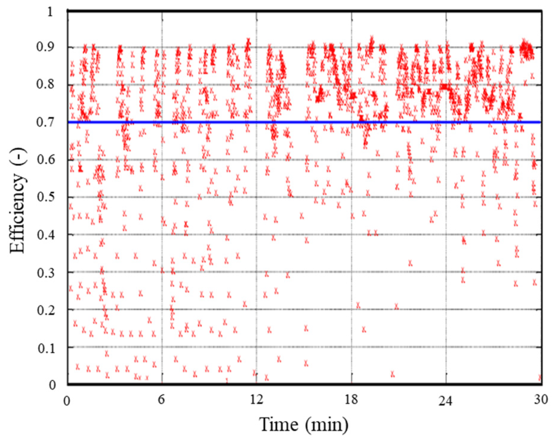
In order to further discuss the efficiency distribution of the FSPM drive system, the efficiency values corresponding to the operating condition points are plotted in Figure 10. It can be seen that the data points are gathered in the region of 0.7 to 0.9. If the efficiency interval (0.7, 1) is selected as the high-efficiency operating condition, the high-efficiency running time of the FSPM drive system accounts for about 84% of the total time during the CLTC-C test.
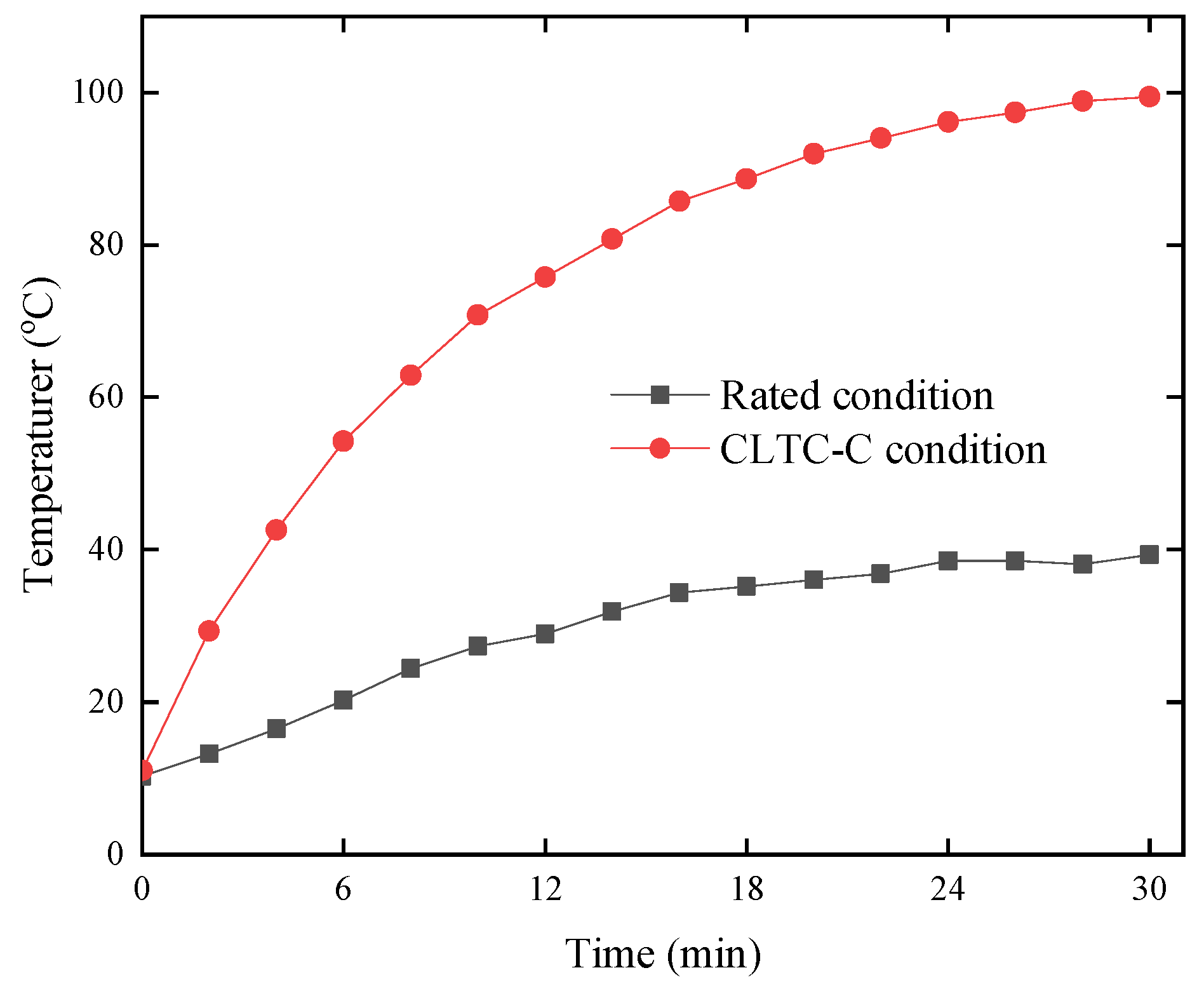
Figure 11 shows a comparison of the motor temperature between the rated condition test and CLTC-C test. The experiments were carried out in the winter (Shaanxi, China). The environment temperature was about 11 °C at the start of the experiments. It can be seen from Figure 11 that the temperature of the FSPM motor increased slowly with operating time in the rated condition; however, it increased rapidly in the CLTC-C condition. This result indicates that the overload and over-speed conditions in the CLTC-C cycle can cause severe heat generation in the FSPM motor, which should be fully considered in practical applications regarding CEVs. In this study, the temperature rise was around 90 °C after the 30 min CLTC-C test. This is negative to the service life of the FSPM drive system. The temperature measurement result suggests that a specialized cooling system should be designed for a CEV with an FSPM drive system. In particular, the concentrated windings of the FSPM motor are all in the stator. When considering this structural feature, a liquid cooling method may be feasible and necessary for the practical application of an FSPM drive system in a CEV. It is important to emphasize that all tests were carried out under simple free-air cooling conditions, which is worse than real-life driving. We are considering setting up a new test bench to simulate real life driving conditions in our next steps.

5. Conclusions

In order to investigate the performance of FSPM motors for pure electric vehicles, a prototype drive system was designed and manufactured in this work. A practical design and optimization method was proposed for a light-duty commercial electric vehicle (CEV). The initial dimensions of the FSPM motor were calculated by theoretical equations referring to a permanent magnet synchronous motor. Then, the dimension parameters were optimized based on 3D-FEA results. A 1/8 FFD with 16 samples was employed to analyze the sensitivity of each parameter. The length of the air gap is the most sensitive parameter to all the other output responses; however, it is usually limited by manufacturing ability. The sensitivities of Ksio, bts, and bpm are larger than those of btr, hys, and htr. Thus Ksio, bts, and bpm were considered the major dimension parameters that should be optimized. Based on the major dimension parameters, second-order RSM models of output performance were established. Finally, the GA method was used to select the optimal point of the RSM models. The GA results converged after the 64th iteration. The result of this work suggests that the proposed RSM and GA optimization methods can effectively achieve convergent solutions for the FSPM optimization problem.
The performance of the designed drive system with an FSPM motor was also investigated in this work. The drive system was assembled into an actual CEV and tested on an experiment bench for commercial vehicles. The results of the steady-state test showed that the designed FSPM motor could work at a 30 N·m load torque for a long time, and work at 60 N·m for a short time, which meets the requirements for light-duty CEVs. Further, the CEV with an FSPM motor was tested according to the driving cycle standard (GB/T 38146.1-2019, China). The results of the real-time speed test showed that the speed deviations of the FSPM drive system are relatively large. Thus, a suppression strategy for torque ripple is necessary for the practical application of the FSPM drive system. The results of the operating condition showed that the average efficiency of the FSPM drive system was between 0.7 and 0.9 during the whole CLTC-C driving cycle. The high-efficiency running time of the FSPM drive system accounted for about 84% of the total time by defining the efficiency interval (0.7, 1) as a high-efficiency range. In addition, the FSPM drive system faces a thermal management issue in practical application in CEVs, discovered through temperature monitoring in this work. The temperature measurement results showed that the temperature rise of the FSPM motor was around 90 °C after 30 min of the CLTC-C test, which is negative to the service life of an FSPM motor. Therefore, the study results in this work suggested that a particular cooling system is necessary for the practical application of an FSPM drive system in a CEV.

Author Contributions

Conceptualization, M.C. and C.Z.; methodology, M.C. and Y.C.; validation, Y.C., G.S. and H.G.; formal analysis, Y.C.; investigation, N.Y. and Y.C.; resources, M.C. and C.Z.; writing—original draft preparation, Y.C.; writing—review and editing, M.C. and C.Z.; visualization, Y.C. All authors have read and agreed to the published version of the manuscript.

Funding

This work is supported by the National Natural Science Foundation of China (No. 62005218), the Science Center for Gas Turbine Project (2022-B-IV-011-001), the Fundamental Research Funds for the Central Universities (CHD) and National Science and Technology Major Project (2017-VII-0001-0094).

Data Availability Statement

No application.

Conflicts of Interest

The authors declare no conflict of interest.

References

  1. Zhou, C.; Huang, X.; Li, Z.; Cao, W. Design consideration of fractional slot concentrated winding interior permanent magnet synchronous motor for EV and HEV applications. IEEE Access 2021, 9, 64116–64126. [Google Scholar] [CrossRef]
  2. Havel, A.; Sobek, M.; Stepanec, L.; Strossa, J. Optimization of Permanent Magnet Parameters in Axial Flux Rotary Converter for HEV Drive. Energies 2022, 15, 724. [Google Scholar] [CrossRef]
  3. Cui, M.; Zhao, S.; Chen, C.; Jing, F. Study on the 12-10 flux switching integrated-starter-generator for hybrid electric vehicle application. Proc. Inst. Mech. Eng. D J. Automob. Eng. 2018, 232, 1667–1676. [Google Scholar] [CrossRef]
  4. Credo, A.; Fabri, G.; Villani, M.; Popesscu, M. Adopting the topology optimization in the design of high-speed synchronous reluctance motors for electric vehicles. IEEE Trans. Ind. Appl. 2020, 56, 5429–5438. [Google Scholar] [CrossRef]
  5. Kang, Y.R.; Son, J.C.; Lim, D.K. Optimal design of IPMSM for fuel cell electric vehicles using autotuning elliptical niching genetic algorithm. IEEE Access 2020, 8, 117405–117412. [Google Scholar] [CrossRef]
  6. Zhao, N.; Schofield, N. An induction machine design with parameter optimization for a 120-kW electric vehicle. IEEE Trans. Transp. Electr. 2020, 6, 592–601. [Google Scholar] [CrossRef]
  7. Camargos, P.H.; Caetano, R.E. A performance study of a high-torque induction motor designed for light electric vehicles applications. Electr. Eng. 2022, 104, 797–805. [Google Scholar] [CrossRef]
  8. Nugraha, Y.U.; Asfani, D.A.; Negara, I.M.Y.; Aziz, M.; Yuniarto, M.N. Technology Review of Electric Motor for Hybrid-Electric Vehicle. In Proceedings of the IEEE Region 10 Conference (TENCON), Auckland, New Zealand, 7–10 December 2021. [Google Scholar] [CrossRef]
  9. Muduli, U.R.; Beig, A.R.; Jaafari, K.; Alsawalhi, J.Y.; Behera, R.K. Interrupt-free operation of dual-motor four-wheel drive electric vehicle under inverter failure. IEEE Trans. Transp. Electr. 2020, 7, 329–338. [Google Scholar] [CrossRef]
  10. Nasr, A.; Gu, C.; Bozhko, S.; Gerada, C. Performance Enhancement of Direct Torque-Controlled Permanent Magnet Synchronous Motor with a Flexible Switching Table. Energies 2020, 13, 1907. [Google Scholar] [CrossRef]
  11. Kiyota, K.; Chiba, A. Design of switched reluctance motor competitive to 60 kW IPMSM in third generation hybrid electric vehicle. IEEE Trans. Ind. Appl. 2013, 48, 2303–2309. [Google Scholar] [CrossRef]
  12. Takahashi, T.; Takemoto, M.; Ogasawara, S.; Ogawa, T.; Arita, H.; Daikoku, A. Development of a Consequent-Pole-PM-Type Axial-Gap Motor With DC Field Winding. IEEE Trans. Ind. Appl. 2021, 57, 4363–4375. [Google Scholar] [CrossRef]
  13. Zhang, G.; Yu, W.; Hua, W.; Cao, R.; Qiu, H.; Guo, A. The Design and Optimization of an Interior, Permanent Magnet Synchronous Machine Applied in an Electric Traction Vehicle Requiring a Low Torque Ripple. Appl. Sci. 2019, 9, 3634. [Google Scholar] [CrossRef] [Green Version]
  14. Kim, K.C. A novel calculation method on the current information of vector inverter for interior permanent magnet synchronous motor for electric vehicle. IEEE Trans. Magn. 2014, 50, 829–832. [Google Scholar] [CrossRef]
  15. Liu, Z.S. Design and Research of Permanent Magnet Brushless DC Direct Drive Hub Motor. In Proceedings of the 4th International Conference on Precision Machinery and Manufacturing Technology (ICPMMT), Taiwan, China, 24–26 May 2019. [Google Scholar] [CrossRef] [Green Version]
  16. He, S.; Fan, X.; Wang, Q.; Chen, X.; Zhu, S. Review on Torque Distribution Scheme of Four-Wheel In-Wheel Motor Electric Vehicle. Machines 2022, 10, 619. [Google Scholar] [CrossRef]
  17. Tan, D.; Wu, Y.; Feng, J.; Yang, K.; Jia, X.; Ma, C. Lightweight design of the in-wheel motor considering the coupled electromagnetic-thermal effect. Mech. Based Des. Struct. 2022, 50, 935–953. [Google Scholar] [CrossRef]
  18. Kobayashi, T.; Katsuyama, E.; Sugiura, H.; Ono, E.; Yamamoto, M. Direct yaw moment control and power consumption of in-wheel motor vehicle in steady-state turning. Vehicle Syst. Dyn. 2017, 55, 104–120. [Google Scholar] [CrossRef]
  19. Han, J.; Ge, B.; Zhang, K.; Wang, Y.; Wang, C. Influence of Control and Structure Parameters on the Starting Performance of a 12/8 Pole Switched Reluctance Motor. Energies 2020, 13, 3744. [Google Scholar] [CrossRef]
  20. Howey, B.; Bilgin, B.; Emadi, A. Design of an External-Rotor Direct Drive E-Bike Switched Reluctance Motor. IEEE Trans. Ven. Technol. 2020, 69, 2552–2562. [Google Scholar] [CrossRef]
  21. Cui, M.; Zhao, S.; Chen, C.; Jing, F. The numerical analysis and experimental study of flux switching motor/generator in HEV applications. Chin. J. Mech. Eng. 2016, 52, 100–105. [Google Scholar] [CrossRef]
  22. Zhao, S.; Liang, J.; Zhao, Y. Optimization design and direct torque control of a flux concentrating axial flux permanent magnet motor for direct drive system. Electr. Power Compon. Syst. 2014, 42, 1517–1529. [Google Scholar] [CrossRef]
  23. Mo, L.; Zhang, T.; Lu, Q. Design and analysis of an outer-rotor-permanent-magnet flux-switching machine for electric vehicle applications. IEEE Trans. Appl. Supercon. 2019, 29, 1–5. [Google Scholar] [CrossRef]
  24. Mirnikjoo, S.A.; Asadi, F.; Abbaszadeh, K.; Abdollahi, S.E. Effect of rotor topology on the performance of counter-rotating double-sided flux switching permanent magnet generator. IEEE Trans. Energy Conver. 2022, 37, 65–74. [Google Scholar] [CrossRef]
  25. Cao, L.; Chau, K.T.; Lee, C.H.; Wang, H. A double-rotor flux-switching permanent-magnet motor for electric vehicles with magnetic differential. IEEE Trans. Ind. Electron. 2020, 68, 1004–1015. [Google Scholar] [CrossRef]
  26. Aboelhassan, M.O.E.; Raminosoa, T.; Goodman, A.; Lillo, L.; Gerada, C. Stator-flux-oriented fault-tolerant control of flux-switching permanent-magnet motors. IEEE Trans. Ind. Electron. 2013, 60, 2997–3006. [Google Scholar] [CrossRef]
  27. Liu, M.; Li, Y.; Sixel, W.; Sarlioglu, B. Design and testing of low pole dual-stator flux-switching permanent magnet machine for electric vehicle applications. IEEE T Ven. Technol. 2019, 69, 1464–1472. [Google Scholar] [CrossRef]
  28. Zohoori, A.; Vahedi, A.; Noroozi, M.A. Design study of FSPM generator with novel outer rotor configuration for small wind turbine application. In Proceedings of the 14th International Conference on Environment and Electrical Engineering (EEEIC), Krakow, Poland, 10–12 May 2014. [Google Scholar]
  29. Hua, W.; Cheng, M.; Zhu, Z.Q.; Howe, D. Design of flux-switching permanent magnet machine considering the limitation of inverter and flux-weakening capability. In Proceedings of the 41st Annual Meeting of the IEEE Industry-Applications-Society (IAS), Tampa, FL, USA, 8–12 October 2006. [Google Scholar]
  30. Hendershot, J.R.; Miller, T.J.E. Design of Brushless Permanent-Magnet Machines; Motor Design Books LLC: Venice, FL, USA, 2010; p. 163. [Google Scholar]
  31. Hanselman, D.C. Brushless Permanent Magnet Motor Design; Magna Physics Publishing: Lebanon, OH, USA, 2003; p. 124. [Google Scholar]
  32. Mahmouditabar, F.; Vahedi, A. Optimum Design of FSPM Motor for Small Water Pump Application Considering Irreversible Demagnetization. Iran. J. Sci. Technol. Trans. Electr. Eng. 2021, 45, 777–788. [Google Scholar] [CrossRef]
  33. GB/T 38146.1-2019; China Automotive Test Cycle-Part 1: Light-Duty Vehicles. Standardization Administration of the P.R.C.: Beijing, China, 2019.
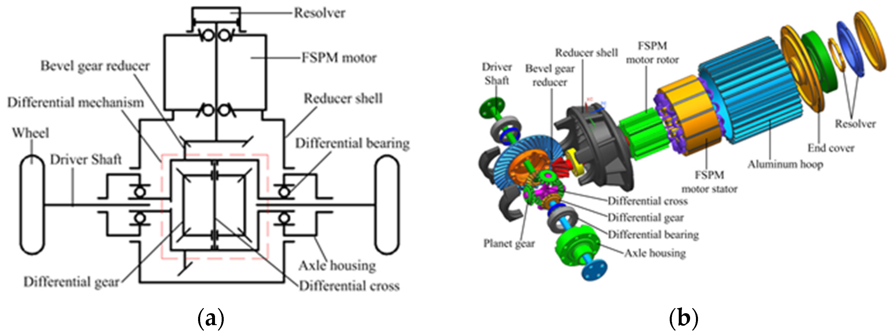
Figure 1. Drive system of a CEV with an FSPM motor. (a) Schematic diagram; (b) assembly structure.
Machines 10 01216 g001
Figure 2. Structure of a 3-phase, 12-stator-tooth, 10-rotor-pole FSPM. (a) Schematic diagram; (b) assembly structure.
Machines 10 01216 g002
Figure 3. Dimension parameters of the FSPM motor.
Machines 10 01216 g003
Figure 4. Flow chart of the optimization process.
Machines 10 01216 g004
Figure 5. Pareto chart of the sensitivities to output performance. (a) Sensitivities to Tout; (b) sensitivities to Tript; (c) sensitivities to Tout/Qpm.
Machines 10 01216 g005
Figure 6. Experimental setup. (a) Prototype of FSPM; (b) drivetrain with FSPM motor; (c) CEV with FSPM motor; (d) experimental bench for vehicles.
Machines 10 01216 g006
Figure 7. Dynamic response and phase current of FSPM. (a) No-load condition; (b) 30 N·m load condition; (c) 65 N·m load condition.
Machines 10 01216 g007
Figure 8. Driving cycle of the experimental test. (a) Speed curve of CLTC-C standard; (b) speed deviation during the test of FSPM.
Machines 10 01216 g008
Figure 9. Distribution of the FSPM motor operating conditions.
Machines 10 01216 g009
Figure 10. Distribution of motor efficiency.
Machines 10 01216 g010
Figure 11. Temperature rise of the FSPM motor during testing.
Machines 10 01216 g011
Table 1. Technical parameters of the FSPM drive system.
ParameterValue
Phase number m3
Rated voltage Voe330 V
Rated current Aoe15 A
Rated power Poe7.5 kW
Rated speed ne2400 rpm
Rated torque Te30 N·m
Maximum speed nmax4000 rpm
Maximum torque Tmax65 N·m
Bevel gear reduction ratio4.2
Tire diameter0.56 m
Table 2. Designed specifications of the FSPM motor.
ParameterValue
Stator outer diameter, Dso166 mm
Stator inner diameter, Dsi96 mm
Stator axial length, La80 mm
Air gap length, δ1.2 mm
Phase number, m3
Stator pole number, Ps12
Rotor pole number, Pr10
Number of turns per phase, Nk180
Stator Slot open width, bslot7.5 Mech. degree
Stator tooth width, bts7.5 Mech. degree
Permanent magnet width, bpm7.5 Mech. degree
Stator yoke height, hys8.2 mm
Rotor tooth width, btr12 Mech. degree
Rotor tooth height, htr12 mm
Table 3. Variable ranges and levels of 1/8 FFD.
LevelKsiobts (°)bpm (°)hys (mm)btr (°)htr (mm)δ (mm)
−10.556.56.58.29121.2
+10.658.58.59.212151.5
Table 4. Variables and levels of central composite design.
LevelKsiobts (°)bpm (°)
−α0.5164.9774.818
−10.5506.0005.500
00.6007.5006.500
+10.6509.0007.500
0.68410.0208.182
Table 5. The materials of each part and their characteristics of the permanent magnet.
PartMaterialsTrademarkMaterial Characteristics
StatorSilicon steel sheet35DW540The thickness of the monolithic piece is 0.35 mm
The iron loss value is 5.4 W/kg (A peak magnetic inductance of 1.5 T and a sinusoidal waveform at a frequency of 50 Hz)
RotorCarbon structural steel20#The tensile strength is 355–500 MPa
The elongation is greater than or equal to 24%
Permanent magnetsNdFeB35SHThe remanence is 1.2 T
The coercivity is 890,000 A/m
The maximum operating temperature is 150 °C
The maximum energy product is 275,000 J/m3
WindingCopper1UEWThe line diameter is 1.5 mm
The conductivity is 580,000,000 S/m
Publisher’s Note: MDPI stays neutral with regard to jurisdictional claims in published maps and institutional affiliations.