Article

Improvement of Steady State Performance of Voltage Control in Switched Reluctance Generator: Experimental Validation

1
LATIS—Laboratory of Advanced Technology and Intelligent Systems, Ecole Nationale d’Ingénieurs de Sousse, Université de Sousse, Sousse 4023, Tunisia
2
Institute for Systems and Computer Engineering, Technology and Science (INESC TEC), Faculty of Engineering, University of Porto, 4200-465 Porto, Portugal
*
Author to whom correspondence should be addressed.
Machines 2022, 10(2), 103; https://doi.org/10.3390/machines10020103
Submission received: 23 December 2021 / Revised: 24 January 2022 / Accepted: 25 January 2022 / Published: 28 January 2022
(This article belongs to the Section Electrical Machines and Drives)

Abstract

:
This paper presents a voltage control approach to a Switched Reluctance Generator (SRG) using a Proportional Integral (PI) controller. The principle of operation is described and the considerations in the design of controller are discussed. A current loop transfer function of an SRG with power converter has been systematically derived in order to obtain a small-signal model for the generator. The generated voltage is controlled by manipulation of the setpoint of the current control of the generator. The entire voltage loop controller and current control have been simulated and tested with a 250 W SRG prototype. The control law of the control system was implemented on a digital signal processor (TMS320F28379D). To verify the feasibility of the proposed voltage control, the performances are evaluated by numerical simulations and experimental tests with an 8/6 SRG for different rotational speeds and resistive loads. Experimental results demonstrate that the DC output voltage from SRG can be controlled well using a simple linear controller.

1. Introduction

The Switched Reluctance Generators (SRGs) are widely used in many industrial applications such as the fields of battery charging, aircraft power systems, and electrical traction [1,2,3,4]. Moreover, the SRG has been suggested as a good alternative for the traditional generator in wind power generation applications. There are several advantages over other generator types, such as: no windings and permanent magnets on the rotor, high power density, high mechanical robustness, good performance in a broad range of speeds, high efficiency, high fault tolerance, and low manufacturing costs [5,6,7]. Taking into account the wide speed range of the SRG, it is possible to eliminate the gearboxes, reducing the mechanical losses and reducing the system costs.
The main disadvantages of SRG are torque ripple, the need of position sensors, and the audible noise. A considerably large effort has been invested in reducing these barriers, as in [8,9]. Some strategies have been proposed in modern studies to avoid the effects of load and speed variation on voltage generation of SRG systems [10,11]. A continuous conduction mode (CCM) for a wind power plant application is proposed with the determination of the optimal control parameters of SRG, as stated in [10]. A specific methodology for the design of SRG is offered in [11] to increase efficiency. In [12], the authors proposed a passivity-based control (PBC) scheme to the active stabilization of an SRG system as a nonlinear source by taking into account the effect of its self-excitation. The current ripple of the SRG is the biggest issue when it works as a battery charger. Therefore, to decrease the current ripple, a power converter and a smart search control (SSC) approach are proposed in [13]. A pulse train (PT) control is used to control the output voltage of the SRG system to obtain a fast response, as designed in paper [14].
As mentioned in [15], an active boost power converter is suggested for the SRG drive that support low voltage DC loads or DC micro grids. In [16], the authors presented a proportional plus resonant (P+RES) to control the power of the SRG. The P+RES controller processes the error between the measured power and its reference by determining the turn-off angle; in this way, the proposed controller reduces the power ripple. A algorithms are proposed to obtain the optimal parameters of an SRG for wind generation systems to reduce the torque ripple, as discussed in [17]. In [18], the authors have introduced a Differential Evolution Strategy (DES) for optimizing the performance of the SRG in wind turbine applications. Three identified parameters (turn-on angle, turn-off angle, and the excitation voltage) are adjusted to maximize the output power. In [19], the authors have developed a direct power control (DPC) in a wide range of speed variations of SRG system. DPCs are suggested by hysteresis current for low-speed operation (DPC-LS) and by a single pulse of current for high-speed operation (DPC-HS) based in sliding mode controllers. To estimate the steady state peak-current of the SRG, a simplified current-rise model for the given operating condition is presented in [20]. As discussed in [21], a microgrid based on a SRG in wind energy application with a plug-in energy support mechanism is presented. The wind SRG is designed and controlled based on dynamic switching offset and robust voltage control. The generated voltage has fast tracking and regulation responses under load conditions and variable speeds. In [7], the authors proposed a model predictive control (MPC) control for SRG driven wind power generation systems. The MPC approach is applied to the phase winding through a z-source converter to generate the desired voltage. To improve the power quality of the grid connected to the SRG, an in-loop filtering methods is presented in [22]. These approaches are based on the elimination of voltage oscillations in the DC link loop due to the SRG switching operation. As mentioned in [23], a bidirectional DC-DC converter connected to the wind system using the SRG to regulate the voltage in an optimal value based on the PI controller. The results have been compared with the conventional wind energy conversion system (WECS). A pulse width modulated (PWM) control technique for SRG is presented in [24]. A comparative assessment among different control strategies of SRG has been performed to verify the superiority of the PWM. In [25], a small-scale wind power generation is proposed combining maximum power tracking control with power balance control. The two-stage inverter is established: voltage closed-loop control in boost circuit of front stage and proportional integral (PI) control in the inverter circuit of the second stage. However, in the industrial world, it is a fact that using more complex control laws may not always lead to better performance than using a simple controller, since the quality of regulation depends not only on the controller but also on the implementation constraints. To put this paper into a more general view, this work presents the results of research demonstrating that a simple approach can be very useful for engineers in need of SRG controllers of low complexity and which are digitally implementable.
In this paper, we present a methodology to pursue simplicity while preserving robustness to load variations when a switched reluctance machine is used as a power generating system. A PI controller is designed in order to maintain the output voltage constant, independently of the mechanical speed and load variations. Moreover, the PI parameters are dependent on the system features, the design is based on small-signal model of SRG for an operating point. The tuning of controller parameters is performed using Bode diagrams and the phase margin criterion. The system response, stability, and steady-state error, analyzed in simulation and validated by experimental results. The paper is organized as follows: Section 2 introduces the basic principles of the SRG and the analysis of operation. Section 3 presents the strategy of SRG voltage control. The experimental and simulation results are described in Section 4.

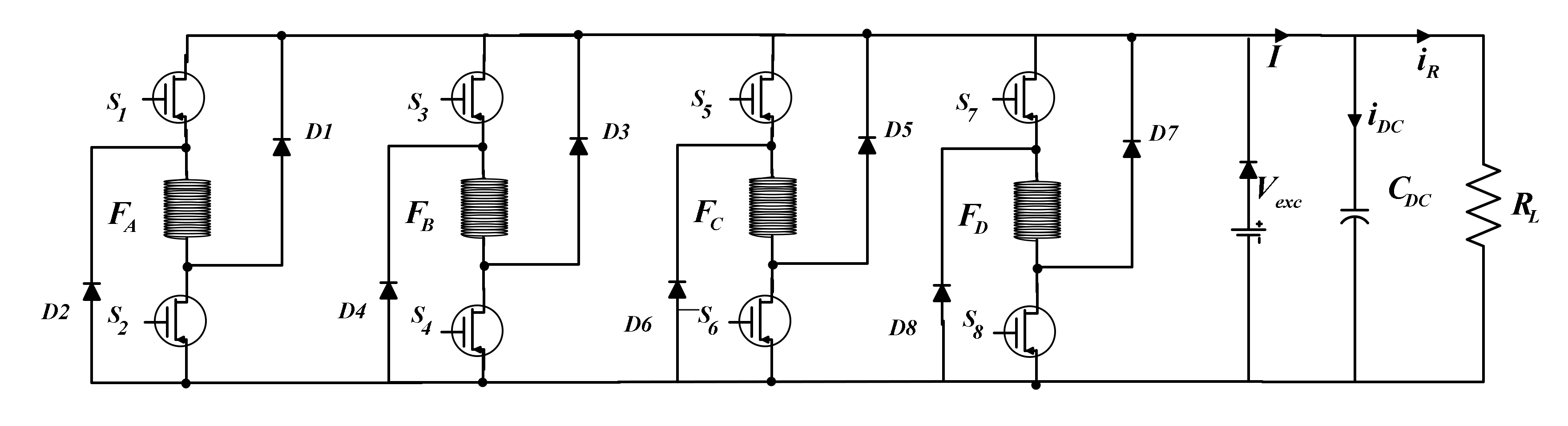
2. Basic Principle of SRG

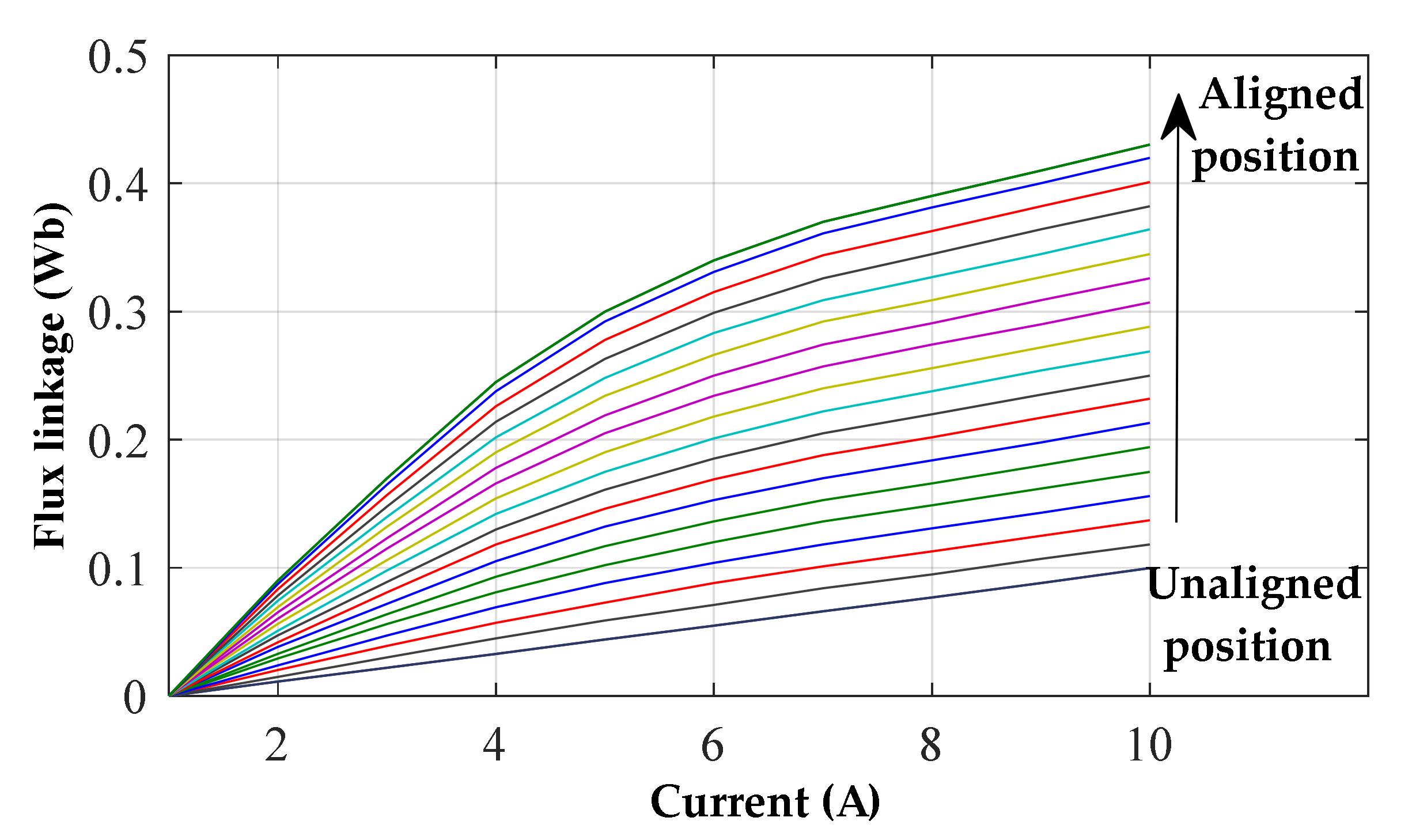
2.1. Analysis of SRG Operation

In the traditional configuration, the SRG is a machine with salient poles in the rotor and in the stator. Windings are only presented in the stator and there is no use of permanent magnets. Due to salient pole configuration and to magnetic saturation of the material, the machine characteristic is highly dependent on the rotor position and current. This characteristic is the reason for the high nonlinearity of the SRG which leads to torque ripple and acoustic noise [26]. In generator operation mode, the phase magnetization of the SRG is made in the negative slope of the inductance profile. Figure 1 presents the generation process. At θon the phase is magnetized to a desired value, and at the same time, the electromotive force increases. At θoff the phase voltage is bigger than the DC voltage, so the current is directed to the DC source by a converter.
The most common converter used to operate the SRG is the asymmetric half bridge converter. Figure 2 shows the schematic of the converter for the excitation and generation mode, respectively, to highlight the principles of the energy production, with phase A as an example. For the SR power generation, the system requires a phase of excitation first, followed by a phase of generation, as shown in Figure 2a. When the inductance is in its decreasing part, the switches S1 and S2 of the converter are closed. The mechanical energy supplied by the IM machine is transformed into magnetic energy and stored in the stator windings of the SRG. After excitation, the switches are opened. The current flows to the load through the freewheeling diodes D1 and D2, as illustrated in Figure 2b. The magnetic energy stored in the windings is transformed into electrical energy and transferred to the load.
As depicted in Figure 2, each converter phase consists of two transistors and two diodes. In the case of Figure 2a the DC source supplies the phase, and in the case of Figure 2b, the phase supplies the source. Figure 3 shows the complete power circuit of the SRG and the converter connected to the load. In the generation process, the DC power source (Vexc) may be required at some transient changes, as is the case of startup. At steady-state operation, it is expected that the capacitor can hold the current variations created by the magnetization and the generation of current in the SRG, resulting in a no-use of the DC power source.
The voltage equation of each SRG phase is given by [27]:
v = r s i + d ϕ ( θ , i ) d t
where i is the phase current, rs is the phase resistance, Φ is phase flux linkage, and θ is the rotor position. The flux in the stator phases varies according to the rotor position θ and the current of each phase and is expressed by:
ϕ ( θ , i ) = L ( θ , i ) i
where L is the inductance. For a non-saturable machine, the simplified equation of voltage based on the precedent equations can be written as:
v = r s i + d ( L ( θ , i ) i ) d t = L ( θ , i ) d i d t + r s i + e
where e represents the back-emf:
e ( ω ) = i   ω   d L ( θ , i ) d θ
with ω = d θ d t as the rotor speed. Without magnetic saturation effect, the instantaneous electromagnetic torque and the mechanical equation are given, respectively, by:
T ( θ , i ) = d W ( θ , i ) d θ = 1 2 i 2 d L ( θ , i ) d θ
T ( θ , i ) = T M + B ω + J d ω   d t  
where TM is the mechanical power, T (θ,i) is the torque of SRG, J is the total inertia and B is the friction coefficient. The complete set of electric motor equations are obtained as follows:
d i d t = r s i L ( θ ) i   ω L ( θ )   d L ( θ , i ) d θ + v L ( θ ) d ω d t = 1 2 J i 2   d L ( θ ) d θ B J ω T M J
The magnetization characteristics of the SRG, used in the result section, is shown in Figure 4. The higher position represents the flux linkage when one rotor pole is completely aligned with the magnetized stator pole, this is the position of higher magnetic saturation. The lower position represents the flux linkage when the stator and rotor poles are completely unaligned.

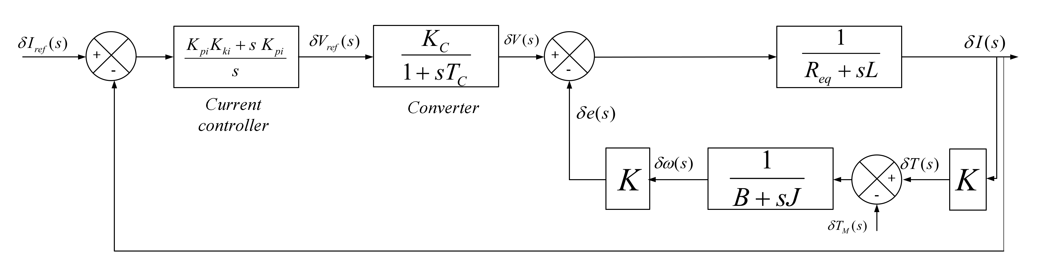
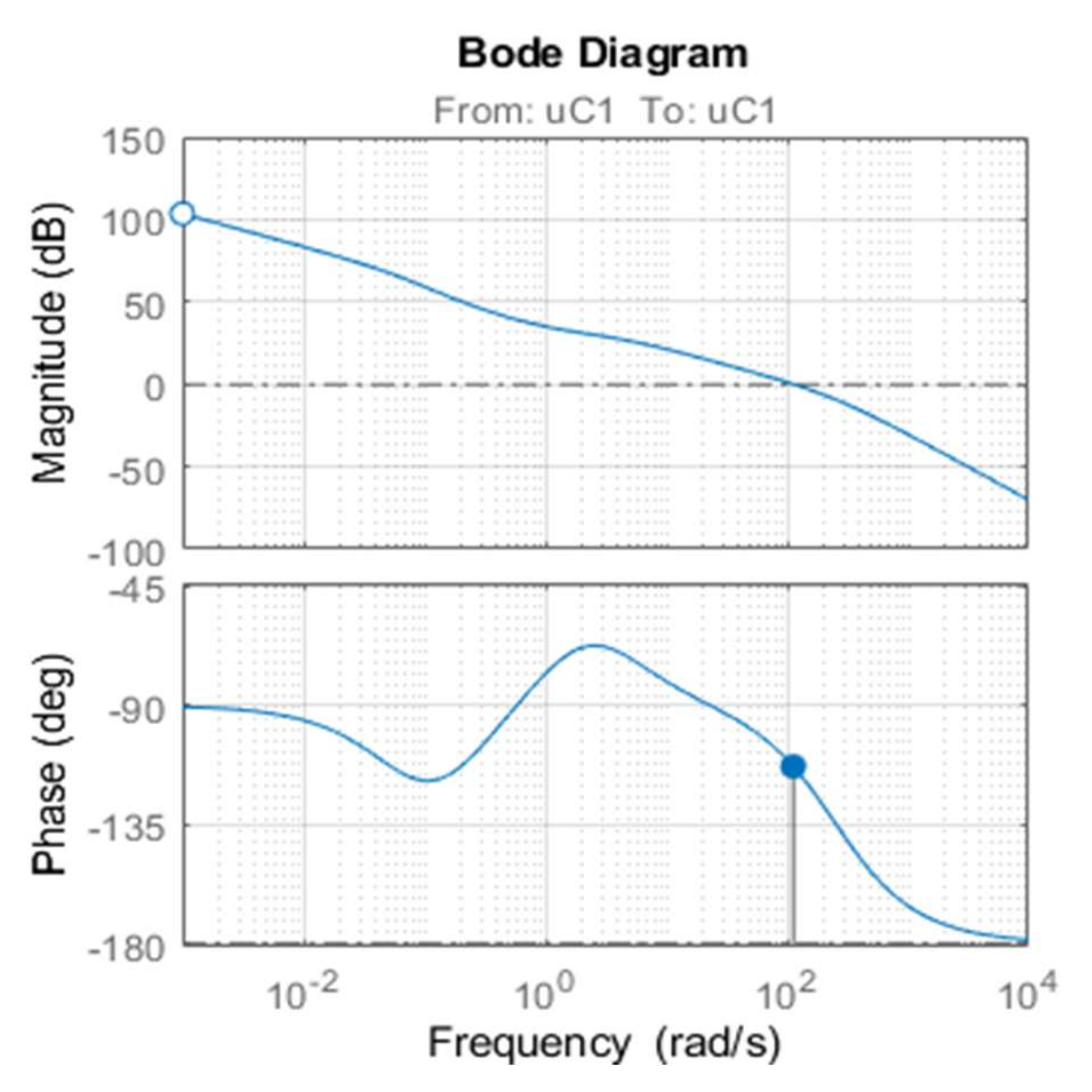
2.2. Model Simplification and Linearization

As stated before, the SRG model is highly non-linear, which makes the design of linear controllers a difficult task. The simplest solution is in linearizing the SRG model for a specific operating point and then applying linear control techniques [28,29]. Even though the validity of this approach has some limitations, this solution is frequently applied in engineering practice with good results.
The first step in linearizing the model is to approximate the variables as:
i = i 0 +   δ i
v = v 0   +   δ v
ω   = ω 0   +   δ ω  
T M = T M 0   +   δ T M
where the index o is used to define the value of the variable at the steady-state operating point and the δ represents the incremental deviations of the variable near that point. The linearized model can be written as:
d δ i d t = R e q L δ i δ e L   + δ V L d δ ω d t = K J δ i B J   δ ω + δ T M J
where the constants are:
R e q = r s   + d L ( θ ) d θ ω 0
K = d L ( θ ) d θ i 0
δ e = d L ( θ ) d θ i 0   δ ω
Hereafter, using the Laplace transformation, the electrical and mechanical equations in the transform domain are given as follows:
δ I ( s ) = δ V ( s ) δ e R e q + s L δ ω ( s ) = K   δ i ( s ) δ T M ( s ) B + s J
For more details see the references [28,29]. Figure 5 shows the block diagram of the linearized SRG. A PI controller is used to control the current, and the power converter is modelled as a gain with a first-order delay, as follows.
E c o n ( s ) = K C 1 + s   T C
The gain of the power converter is given by:
K C = V D C n o min a l V m a x
where Vmax is the maximum control voltage. The time constant of the converter Tc is one approximation of the dead time of the power converter, the sampling and signal processing. The sum of these very small-time constants is approximated by:
T C = T 2 = 1 2   f
where f is the switching frequency of the converter. The transfer function of the current controller is given by:
δ I ( s ) δ V ( s ) = B + s J L J   s 2 + ( R e q J + L B )   s + ( R e q B + K 2 )

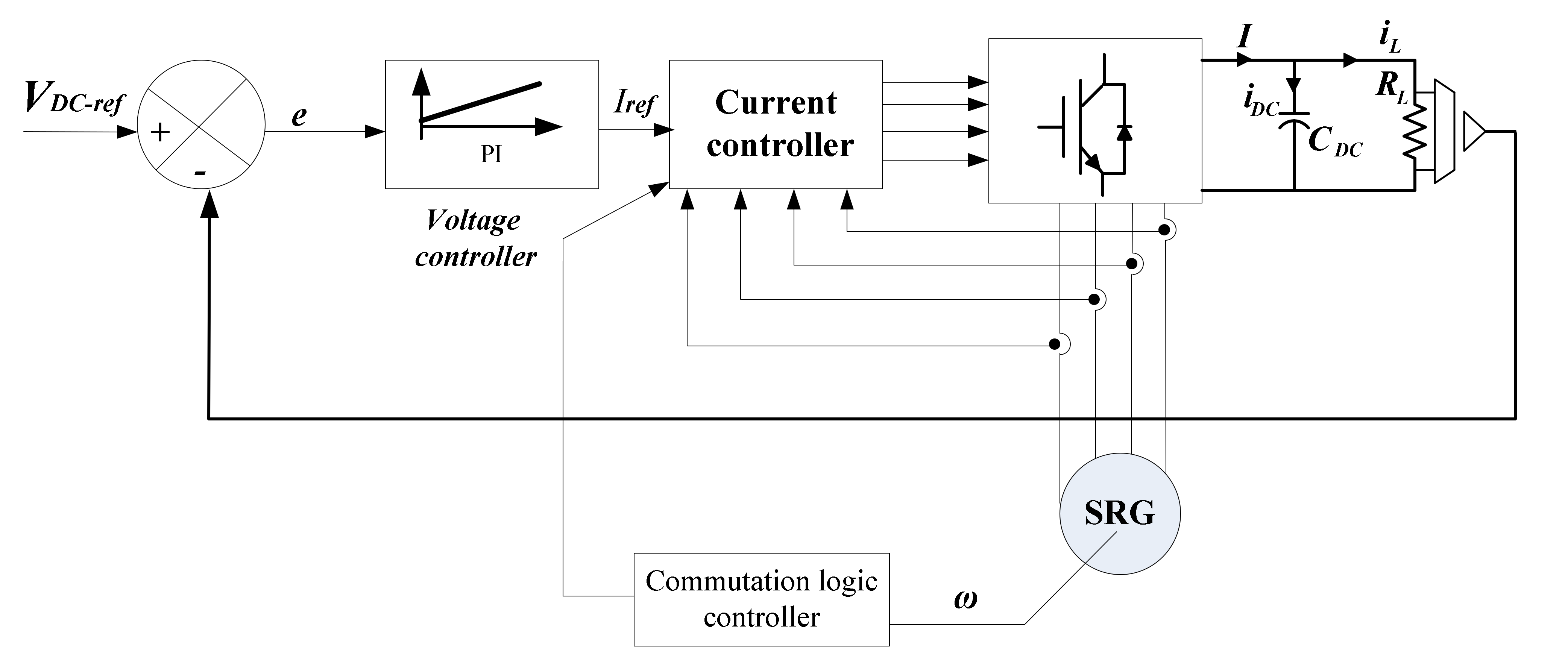
3. SRG Voltage Control
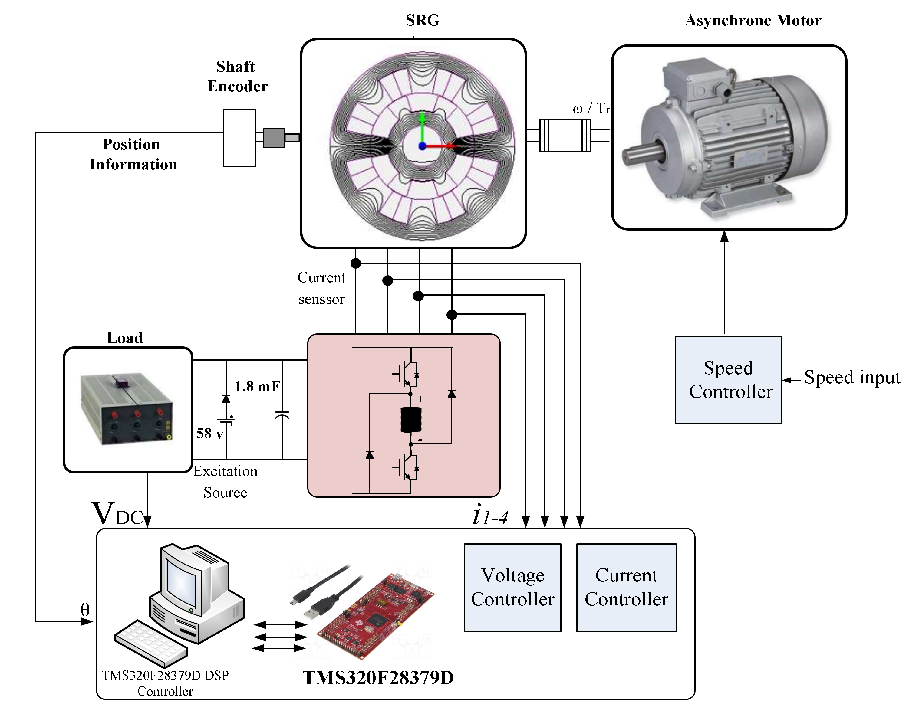
3.1. Control Scheme

The primary objective in a power generator is to maintain the DC output voltage at a constant value, despite variation of the load or variation in the generator mechanical supply, as is the case of wind speed variation in wind turbines.
For this reason, the controller is designed in a cascade loop configuration, where the outer loop is the voltage control of the DC capacitor, and the inner loop is the current control of the generator. Figure 6 shows this diagram.
The controllers must be designed according to the specifications and application of generator. For simplicity of implementation, a PI controller is chosen for the voltage controller. To ensure the system performance, minimum of steady-state error, and a fast response, we are tuning the PI controller. Nevertheless, the setting of PI parameters is called the process characteristics of the system. The transfer function of the PI controller is given by:
C v ( s ) = K p + K i s

3.2. Synthesis of the Controller

The goal of this section is to present a process to design the linear controller for the SRG capacitor voltage loop. Figure 7 shows the voltage control scheme. As current dynamic is much faster than the capacitor voltage loop, current closed-loop transfer function can be approximated by a unity function [22]. In the scheme, the measured DC bus voltage at the capacitor terminals (VDC) is compared to the reference voltage (VDC-ref), then the controller generates a current reference (Iref) that minimizes the controller error (VDC-ref ࢤ VDC). The capacitor and load dynamic are given by:
F ( s ) = R L R L C D C   s + 1
For the controller design the sisotool and root locus in control system is used. The closed-loop transfer function of the DC bus voltage is given by:
δ V D C ( s ) δ V D C ( s ) = C v ( s )   δ I ( s ) δ I ( s )   R L R L C D C   s + C v ( s )   δ I ( s ) δ I ( s ) R L + 1
The chosen steady-state operating point has a current of 3 A and a speed of 62.8 rad/s. For the Resistive load (RL) was chosen 150 Ω and for the capacitor (CDC) 1.8 mF. The parameters of the PI controller are chosen to achieve a settling time inferior to 10 ms. Figure 8 illustrates the responses of the voltage based on the root locus. The Bode diagram of the compensated system is shown in Figure 9. The chosen crossover frequency is 100 Hz with a phase margin system of 50.3°. The chosen gain of the speed controller at the time constant 0.02 s is giving as a PI controller in the form:
C V ( s ) = 0 . 77 + 6 . 09 s

4. Simulation and Experimental Verification

4.1. Experimentation

In order to validate the feasibility of the proposed voltage controller, an experimentation of the SRG system is carried out. The parameters of the 8/6 SRG system are listed in Appendix A. Figure 10 depicts the experimental setup. The hardware setup is composed by a power converter with a dc-link capacitor of 1.8 mF and an induction motor that emulates the mechanic power of the wind.
An asymmetric half bridge converter is used to control the operation of SRG composed. To measure the position, an encoder is mounted on the rotor of the SRG. The PC indicated in Figure 10 is used to write, edit and the download the software programs to the Digital Signal Processor (DSP) which executes the controller algorithms. The control board comprises a DSP, data acquisition system and interface circuits for the power converter. For digital implementation of the proposed control, a DSP controller TMS320F28379D from Texas Instruments is used. The excitation source and load are connected in parallel at the DC bus, as shown in Figure 10.

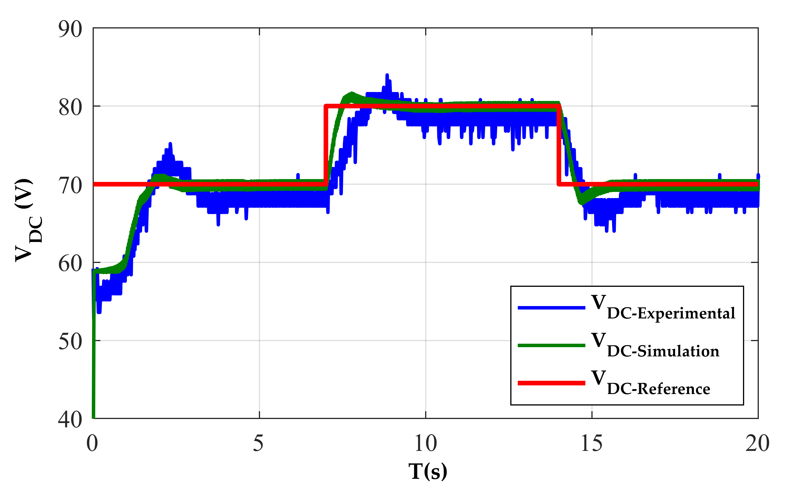
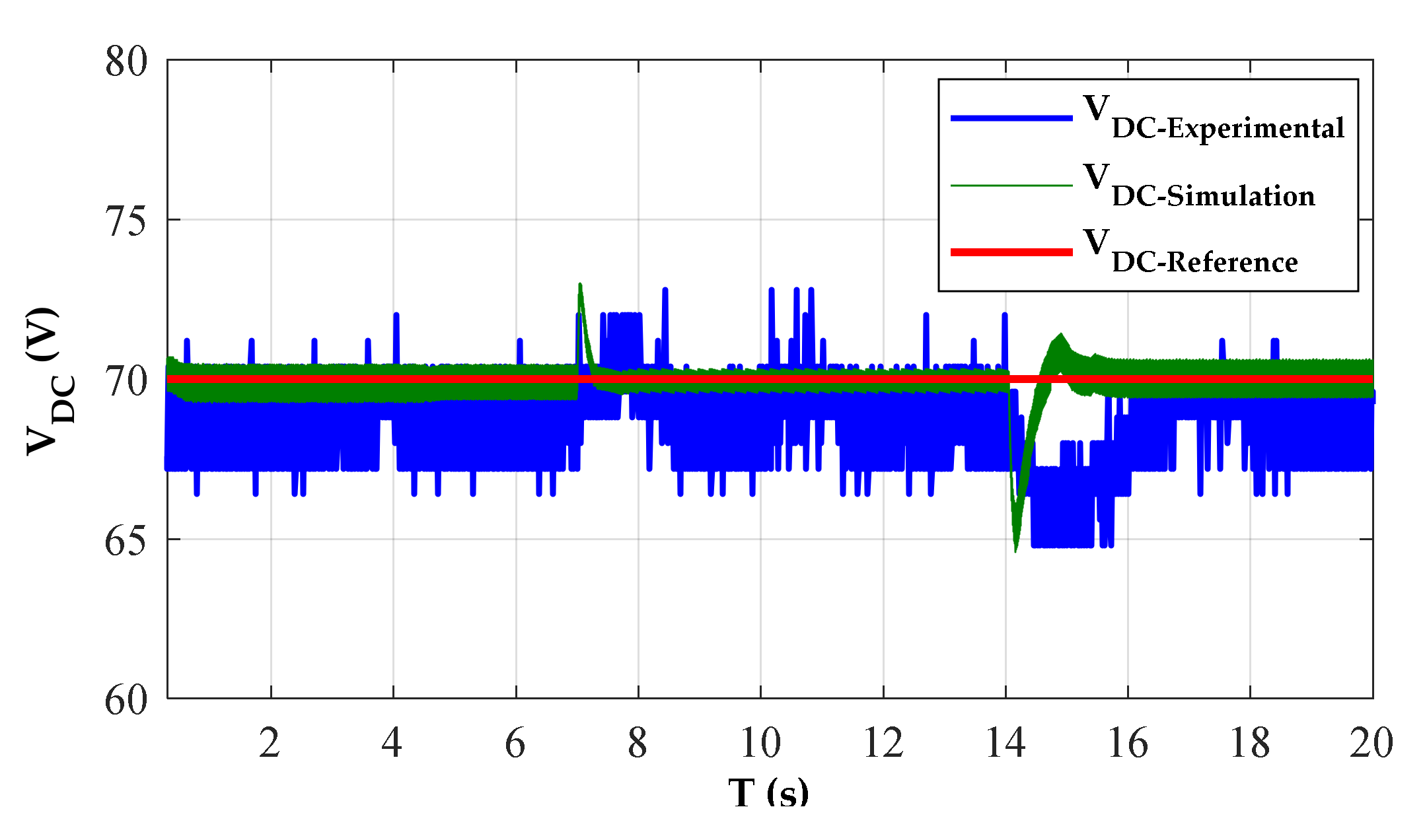
4.2. Discussion of Simulation and Experimental Results

To investigate the voltage regulation performances, the simulation results and the validation experimental of the proposed control strategy for a SRG are presented in this section. The software MATLAB/SIMULINK is used for the simulation.
The SRG is operated in self-excitation. The SRG requires an external voltage source to ensure the initial magnetization of the phases. A battery (Vexc = 58 V) in series with a diode is placed on the DC bus to excite the machine at start-up. The diode keeps the current returning to the battery during the production. When the capacitor voltage is charged initially, the battery is automatically disconnected and the excitation current is supplied by the capacitor. No energy is taken from the battery.
Figure 11 shows that the controller was able to regulate the DC voltage in 20 s. It can be seen from Figure 11, when the SRG runs at a stable state with a constant speed 600 r/min, the tracking of the dc voltage to its reference is close enough. We can observe a good performance of the DC bus voltage regulation. The voltage controller responds very promptly to follow the voltage reference regardless of some ripples. It can be observed that the output voltage obtained by applying the PI control method requires about 0.92 s to reach a stable state with overshoot 3 V. Consequently, the PI controller responds faster. Figure 12a shows the capacitor current, the one phase current of SRG, and the voltage of DC bus. Due to the noises, the waveforms of the currents (iA and iDC) are invisible and are shown further in Figure 12b. The simulated and measured voltage ripples comparison under various voltages of the DC bus is presented in Table 1.
In experimental results, there is a significant reduction of ripples in the DC bus at high voltage reference. A cause of experimental conditions, there is a difference between the simulation and the measured results of the voltage ripple. The impact of speed variation on the DC bus voltage at the resistance load of 333 ohms and at the reference voltage value was set at 70 V, as shown in Figure 13. The bus voltage is well regulated at the reference voltage of 70 V. We observe the response times are approximately the same as the experimental values. The steady state is recovered in 1 s after the first perturbation and 1.5 s for the second. Figure 14 shows the capacitor current, the one phase current of SRG, and the voltage of DC bus.
In experimentation, the perturbations of speed variation at t1 = 7 s and t2 = 14 s are well rejected with an increase of 2 V after t1 and decrease 5 V after t2. In simulation, the overshoot after the two perturbations is 2.5 V and 5 V. This transient test shows the effectiveness of the PI controller strategy during wind speed fluctuation. From Table 1, there is a decrease in voltage ripples at high speeds. To evaluate the effect of load variation on the DC bus control, the following test is performed: The reference value of the DC bus voltage is set to 70 V and the rotation speed is 600 rpm. At t = 12 s, the load resistance decreases from 400 to 333. The results displayed in Figure 15 and Figure 16 show that the voltage control is well executed for the different loads. The results demonstrate that the PI controller is able to keep track of the reference DC voltage despite some ripples. The influence on voltage ripples has limited with load variation, as shown in Table 1.

5. Conclusions

To improve the performance of the SRG power generation system, the PI control method is proposed in this paper. The SRG model has used the state-space of the SRG with look-up tables extracted from the FEM, which increases the accuracy of the model. An experimental test bench was developed and built to validate the robustness of voltage regulation of an SRG with PI control. The major contributions of this study are: The SRG system under the PI controlled method can achieve a rapid response during start-up and establish the steady state of system. Therefore, the PI control method has a good response capacity for variable wind speed and load conditions which makes the machine even more attractive for wind generation systems. The proposed control enables a flat-top of current waveform with a low ripple and a very low overshoot in the output voltage of the SRG. The second significant observation we can make is that our control law requires few computational resources to be implemented with success. The approach discussed constitutes a viable alternative to complex methods of the design used in the construction of controllers for SRG systems. Here we can benefit fully from the simplicity of the control law so that the different specifications can easily be exploited and tested.

Author Contributions

Conceptualization, Z.T., R.E.A. and A.K.; methodology, R.E.A. and A.K.; validation, Z.T., M.P., R.E.A. and A.K.; formal analysis, Z.T., R.E.A. and A.K.; investigation, Z.T., M.P., R.E.A. and A.K.; resources, Z.T. and R.E.A.; data curation, Z.T.; writing—original draft preparation, Z.T.; writing—review and editing, Z.T., M.P., R.E.A. and A.K.; supervision, R.E.A.; funding acquisition, A.K. All authors have read and agreed to the published version of the manuscript.

Funding

This study was financed in part by the University of Sousse, in part the participation of Manuel Pereira by National Funds through the Portuguese funding agency, FCT—Fundação para a Ciência e a Tecnologia, under Scholarship SFRH/BD/04583/2020. And the participation of Rui Esteves Araújo in this work was financed by National Funds through the Portuguese funding agency, FCT—Fundação para a Ciência e a Tecnologia, within project UIDB/50014/2020.

Institutional Review Board Statement

Not applicable.

Informed Consent Statement

Not applicable.

Conflicts of Interest

The authors declare no conflict of interest.

Appendix A

Table A1 shows data prototype 8/6 SRG.
Table A1. Database of 8/6 SRG.
CharacteristicsValues
Output power250 W
Current maximum3 A
Inductance (aligned position)0.14 H
Inductance (unaligned position) 0.021 H
Viscous friction0.01 Nms
Moment of inertia0.006 Kgm2
Resistance of phase winding5 Ω

References

  1. Yu, D.; Hua, Y.; Yu, S.; Zhang, P.; Iu, H.H.C.; Fernando, T. A New Modulation–Demodulation Approach to DC Power-line Data Transmission for SRG-Integrated Microgrid. IEEE Trans. Power. Electron. 2020, 11, 12370–12382. [Google Scholar] [CrossRef]
  2. Cheng, H.; Wang, L.; Xu, L.; Ge, X.; Yang, S. An Integrated Electrified Powertrain Topology with SRG and SRM for Plug-In Hybrid Electrical Vehicle. IEEE Trans. Ind. Electron. 2020, 10, 8231–8241. [Google Scholar] [CrossRef]
  3. Mosaad, M.I. Direct power control of SRG-based WECSs using optimised fractional-order PI controller. IET Electr. Power Appl. 2020, 3, 409–417. [Google Scholar] [CrossRef]
  4. Hong, C.-M.; Chen, C.-H. Enhanced radial fuzzy wavelet neural network with sliding mode control for a switched reluctance wind turbine distributed generation system. Eng. Optim. 2018, 7, 1133–1151. [Google Scholar] [CrossRef]
  5. Dos Santos Neto, P.J.; dos Santos Barros, T.A.; De Paula, M.V.; Filho, E.R.; Vasquez, J.C.; Guerrero, J.M. Wind Distributed System Based on Switched Reluctance Generator Using a Bidirectional DC-DC Converter with Sliding Mode Control. In Proceedings of the IECON 2019 – 45th Annual Conference of the IEEE Industrial Electronics Society, Lisbon, Portugal, 14–17 October 2019. [Google Scholar] [CrossRef]
  6. Li, Z.; Yu, X.; Qian, Z.; Wang, X.; Xiao, Y.; Sun, H. Generation Characteristics Analysis of Deflection Type Double Stator Switched Reluctance Generator. IEEE Access. 2020, 8, 196175–196186. [Google Scholar] [CrossRef]
  7. Kiani, E.; Ganji, B.; Taher, S.A. Model predictive control of switched reluctance generator based on Z-source converter for wind power applications. Int. Trans. Electr. Energy Syst. 2020, 11, 12578. [Google Scholar] [CrossRef]
  8. Gan, C.; Wu, J.; Sun, Q.; Kong, W.; Li, H.; Hu, Y. A Review on Machine Topologies and Control Techniques for Low-Noise Switched Reluctance Motors in Electric Vehicle Applications. IEEE Access. 2018, 6, 31430–31443. [Google Scholar] [CrossRef]
  9. Sun, X.; Wu, J.; Wang, S.; Diao, K.; Yang, Z. Analysis of torque ripple and fault-tolerant capability for a 16/10 segmented switched reluctance motor in HEV applications. COMPEL - Int. J. Comput. Math. Electr. Electron. Eng. 2019, 6, 1725–1737. [Google Scholar] [CrossRef]
  10. Ćalasan, M.P.; Vujičić, V.P. A robust continuous conduction mode control strategy of switched reluctance generator for wind power plant applications. Electr. Eng. 2016, 3, 943–958. [Google Scholar] [CrossRef]
  11. Dias, R.J.; Silva, C.R.; dos Santos, B.R.; dos Santos Costa, C.; da Silveira, A.F.V.; de Andrade, D.A. Innovations on Design of 6×4 and 6×6 Switched Reluctance Generators for Increasing the Efficiency. IEEE Lat. Am. Trans. 2017, 4, 646–655. [Google Scholar] [CrossRef]
  12. Namazi, M.M.; Koofigar, H.R.; Ahn, J.W. Active Stabilization of Self-Excited Switched Reluctance Generator Supplying Constant Power Load in DC Microgrids. IEEE Trans. Emerg. Sel. 2021, 3, 2735–2744. [Google Scholar] [CrossRef]
  13. Roshandel, E.; Namazi, M.M.; Rashidi, A.; Saghaian-Nejad, S.M.; Ahn, J.W. SSC strategy for SRG to achieve maximum power with minimum current ripple in battery charging. IET Electr. Power Appl. 2017, 7, 1205–1213. [Google Scholar] [CrossRef]
  14. Zan, X.; Cui, M.; Yu, D.; Xu, R.; Ni, K. Improvement of the Response Speed for Switched Reluctance Generation System Based on Modified PT Control. Energies 2018, 8, 2049. [Google Scholar] [CrossRef] [Green Version]
  15. Wang, Q.; Chen, H.; Cheng, H.; Yan, S.; Abbas, S. An Active Boost Power Converter for Improving the Performance of Switched Reluctance Generators in DC Generating Systems. IEEE Trans. Power Electron. 2020, 5, 4741–4755. [Google Scholar] [CrossRef]
  16. Chirapo, K.A.C.; Oliveira, A.L.; Sguarezi Filho, A.J.; Pelizari, A.; Di Santo, S.G.; Costa, E.C.M. P+RES Controller Applied to the Direct Power Control of Switched Reluctance Generator. J. Control. Autom. Electr. 2020, 2, 360–366. [Google Scholar] [CrossRef]
  17. Barros, T.A.; Neto, P.J.; Filho, P.S.N.; Moreira, A.B.; Ruppert, E. Approach for performance optimization of switched reluctance generator in variable-speed wind generation system. Renew. Energy. 2016, 97, 114–128. [Google Scholar] [CrossRef]
  18. Yahia, H.; Liouane, N.; Dhifaoui, R. Differential evolution method-based output power optimisation of switched reluctance generator for wind turbine applications. IET Renew. Power Gener. 2014, 7, 795–806. [Google Scholar] [CrossRef]
  19. Dos Santos Barros, T.A.; dos Santos Neto, P.J.; Nascimento Filho, P.S.; Moreira, A.B.; Ruppert Filho, E. An Approach for Switched Reluctance Generator in a Wind Generation System with a Wide Range of Operation Speed. IEEE Trans. Power Electron. 2017, 11, 8277–8292. [Google Scholar] [CrossRef]
  20. Kushwaha, A.; Kanagaraj, R. Peak-current estimation using simplified current-rise model of switched reluctance generator operating in single-pulse mode. Int. J. Electr. Power Energy. Syst. 2020, 120, 105971. [Google Scholar] [CrossRef]
  21. Lu, M.Z.; Jhou, P.-H.; Liaw, C.M. Wind Switched-Reluctance Generator Based Microgrid with Integrated Plug-In Energy Support Mechanism. IEEE Trans. Power Electron. 2021, 5, 5496–5511. [Google Scholar] [CrossRef]
  22. Hancco Catata, E.O.; Dos Santos Neto, P.J.; De Paula, M.V.; Carvalho, J.P.; Barros, T.A.S.; Ruppert, E. In-Loop Adaptive Filters to Improve the Power Quality of Switched Reluctance Generator in WECS. IEEE Access. 2021, 10, 2941–2951. [Google Scholar] [CrossRef]
  23. Dos Santos Neto, P.J.; dos Santos Barros, T.A.; Catata, E.H.; Ruppert Filho, E. Grid-connected SRG interfaced with bidirectional DC-DC converter in WECS. IEEE Trans. Energy Convers. 2021, 4, 3261–3270. [Google Scholar] [CrossRef]
  24. Sarker, R.; Sengupta, D.; Datta, A. PWM Control Technique for Switched Reluctance Generator in Variable Speed Applications. In Recent Advances in Power Electronics and Drives; Kumar, J., Jena, P., Eds.; Springer: Berlin, Germany, 2021; pp. 339–350. [Google Scholar] [CrossRef]
  25. Chen, H.; Xu, D.; Deng, X. Control for power converter of small-scale switched reluctance wind power generator. IEEE Trans. Power Electron. 2020, 4, 3148–3158. [Google Scholar] [CrossRef]
  26. Takayama, K.; Miki, I. Design of switched reluctance motor to reduce acoustic noise. In Proceedings of the 2016 International Symposium on Power Electronics, Electrical Drives, Automation and Motion (SPEEDAM), Capri, Italy, 22–24 June 2016. [Google Scholar] [CrossRef]
  27. Sarr, A.; Bahri, I.; Berthelot, E.; Kebe, A.; Diallo, D. Switched Reluctance Generator for Low Voltage DC Microgrid Operation: Experimental Validation. Energies 2020, 12, 3032. [Google Scholar] [CrossRef]
  28. Krishnan, R. Switched Reluctance Motor Drives, 1st ed.; CRC Press: Boca Raton, FL, USA, 2001. [Google Scholar]
  29. Pereira, M.; Araújo, R.E. Analysis and Design of a Speed Controller for Switched Reluctance Motor Drive. U. Porto J. Eng. 2019, 1, 46–58. [Google Scholar]
Figure 1. Inductance curve versus rotor position.
Machines 10 00103 g001
Figure 2. SRG operating modes (a) excitation mode and (b) generation mode.
Machines 10 00103 g002
Figure 3. Schematic of the Asymmetric Half bridge Converter.
Machines 10 00103 g003
Figure 4. 8/6 SRG magnetization characteristics versus current at different rotor positions.
Machines 10 00103 g004
Figure 5. Schematic diagram of the linearized SRG.
Machines 10 00103 g005
Figure 6. SRG voltage control scheme.
Machines 10 00103 g006
Figure 7. Block diagram of the voltage-controlled SRG system.
Machines 10 00103 g007
Figure 8. Step response of voltage loop.
Machines 10 00103 g008
Figure 9. Bode diagram of the controller system.
Machines 10 00103 g009
Figure 10. Experimental test bench.
Machines 10 00103 g010
Figure 11. Voltage generated with PI controller, at RL = 333 Ω and w = 600 rpm.
Machines 10 00103 g011
Figure 12. Experimental results of SRG: (a) Experimental waveforms of DC link voltage, phase current, and DC link current for different reference voltage at RL = 333 Ω and w = 600 rpm, (b) Zoom of Figure 12a at VDC-ref = 90 V.
Machines 10 00103 g012aMachines 10 00103 g012b
Figure 13. DC bus voltage regulation for different shaft speed, at RL = 333 Ω and VDC-ref = 70 V.
Machines 10 00103 g013
Figure 14. (a) Experimental waveforms of DC link voltage, phase current, and DC link current for different shaft speed at RL = 333 Ω and VDC-ref = 70 V, (b) Zoom of Figure 14a at w = 500 rpm.
Machines 10 00103 g014
Figure 15. SRG operation in self-exited mode under variable load, at w = 600 rpm and VDC-ref = 70 V.
Machines 10 00103 g015
Figure 16. (a) Experimental results (DC link voltage, phase current, and DC link current) under variable load at VDC-ref = 70 V and w = 600 rpm, (b) Zoom of Figure 16a at RL = 400 Ω.
Machines 10 00103 g016
Table 1. Voltage ripple comparison between measurement and simulation results.
Torque Ripple VariationSimulationMeasurement
Voltage70 V1.57%4.65%
80 V1.25%4.04%
90V1.18%3.40%
Speed500 rpm1.85%4.65%
600 rpm1.67%4.64%
750 rpm1.04%4.62%
Load resistance333 Ω1.43%4.65%
400 Ω1.43%4.65%
Publisher’s Note: MDPI stays neutral with regard to jurisdictional claims in published maps and institutional affiliations.

