Abstract
The ambient vibration in manufacturing and assembly plants caused by nearby large equipment or heavy vehicles can produce dynamic machining error and even generate chatter in machining systems such as robotic drilling systems. In this paper, we present an active control method with a magnetorheological damper (MRD) for reducing ambient vibration in a robotic machining system, with the advantages of wider frequency bandwidth and robustness. A sliding mode control (SMC) algorithm is proposed as well. The control performance of the SMC under different excitations is simulated by Simulink and compared with that of the PID control algorithm; the result shows that the SMC is superior to the PID control and passive vibration control. An MRD is designed based on the control force of the active vibration control in the time domain in order to provide the required damping force. The results of co-simulation using ADAMS and Simulink verify that the ability of the SMC to control vibration performance is significantly improved compared with that of the passive vibration control.
1. Introduction
The ambient vibration in an airplane assembly plant caused by nearby huge equipment or heavy vehicles will transfer to the robotic machining system through the ground and produce dynamic error or even generate chatter in robotic machining processes. The ambient vibration is a random vibration with wide bandwidth, several vibration sources and a complex transmission path, which may be a sinusoidal wave from rotating machines, a random wave from moving heavy vehicles, or a transient wave from stamping equipment. Therefore, the dynamic excitations in the working system have very complex spectral frequency characteristics and various random intensities.
In a traditional passive linear vibration control system, the system stiffness and the natural frequency cannot be adjusted. The vibration isolation frequency domain of the control system is limited, which results in poor controllability and adaptability of the ambient vibration with a wide frequency band. Nonlinear mechanisms such as quasi-zero stiffness (QZS) mechanisms have been introduced to optimize the vibration control structure. Research has shown that a vibration control system with a QZS mechanism can reduce the natural frequency without penalizing the bearing capacity, and can broaden the frequency band of the vibration isolation system effectively as well. In 1989, the quasi-zero stiffness vibration isolation system was first comprehensively described by Alabuzhev et al. [1]. The quasi-zero stiffness vibration isolation system is a typical nonlinear mechanism that can reduce the natural frequency of the system while ensuring its carrying capacity, which effectively broadens the frequency band of the vibration control system. A QZS vibration control system consisting of a vertical spring in parallel with inclined springs was presented by Carrella et al. [2,3]; it was verified by simulation and experiment that the quasi-zero stiffness structure broadens the vibration isolation frequency band of the system. At present, quasi-zero stiffness mechanisms have been widely used in the field of vibration control of low frequency bands [4,5,6].
However, resonance may occur when the excitation frequency is close to the natural frequency due to the lack of adjustable capability in the passive vibration control system. In order to avoid resonance and further improve the vibration suppression effect of the vibration control system, researchers often introduce active control strategies to regulate the vibration control system according to excitation frequency in order to optimize the passive vibration control system.
A fuzzy PD hybrid control algorithm that integrates the advantages of the two control methods and implements the active control of low-frequency, large-displacement vibration was proposed for a satellite ring antenna by Zhai et al. [7]. Chen et al. [8] developed an active vibration control method to suppress the vibration of an aircraft tail model support system under wind excitation, and established a control system with a piezoelectric actuator based on an adaptive internal model control algorithm. A Stewart platform is often used as a connection, isolation and vibration suppression mechanism between a satellite and precise load and a device. An active vibration control method based on energy was developed by Giorgio et al. [9] to suppress vibrations of the end effector of a robot arm with a dissipative control action. A control method combining adaptive filtering and Skyhook for a Stewart platform was indicated by Wang et al. [10]; their experimental results demonstrated that the proposed method has robust stability compared with single adaptive filtering control. A Stewart platform equipped with a piezoelectric actuator for active micro-vibration isolation along with a control algorithm combining the direct feedback of integrated forces with adaptive feedback based on FxLMS was introduced by Wang et al. [11]. The experimental results exhibited that the attenuation performances of both periodical and random disturbances in the frequency range of 5–200 Hz were significantly effective. An improved adaptive filtered-x normalized least-mean-square (FxNLMS) algorithm was proposed by Yi et al. [12] to achieve active micro-vibration isolation.
A micro-vibration isolation control system based on a Lorentz force actuator was proposed by Wen [13] to actively control negative stiffness for large precision instruments; the system was connected in parallel with an air spring to further reduce the natural frequency. A new type of effective vibration isolation platform for precision devices using an optimization strategy based on the minimum energy loss rate was designed by Sun et al. [14]. The ability of the platform to isolate complex spatial micro-vibrations in the low-frequency range below 5 Hz was verified by experiments. The air spring approach has the significant advantage of low-frequency vibration suppression; a 6-DOF active vibration isolation unit equipped with an air spring was designed by Pan et al. [15], which was applied to a precision vibration reduction platform system in combination with an LQR optimal control strategy. Improved performance of vibration isolation was verified by both simulation and experiments. A hybrid mount actuator combining an air spring with a magnetorheological damper based on a single PID control was presented by Han et al. for active vibration control in the precision manufacturing stage [16].
Ma et al. [17] developed a semi-active suspension with a magnetorheological fluid damper, and proposed a fuzzy skyhook controller with grey wolf optimizer algorithm based on a new neural-inverse model of magnetorheological fluid, which improved vehicle vibration suppression. A fuzzy sliding mode control strategy for semi-active air suspension based on a magnetorheological (MR) damper was proposed by Hu et al. [18] and the model of a quarter vehicle semi-active air suspension system equipped with a MR damper was established to obtain stronger vibration attenuation and ride comfort. An active vibration control system with a magnetorheological damper for vibration suspension of a vehicle seat based on a back-stepping sliding mode control method was presented by Zhang et al. [19]. Experimental results demonstrated that the proposed controller was superior to other control and passive systems. A 5-DOF driver and seat suspension system model for active vibration control was established by Zhao et al. [20] and a quick identification method of seat-occupant system parameters based on vibration measurement data optimized by a multi-objective Genetic Algorithm was proposed. In order to improve the attenuation performance of a semi-active seat suspension system based on magnetorheological damper, a new intelligent optimization method of PID parameters to regulate the stiffness of magnetorheological damper and actively control vibration was proposed by Liu et al. [21].
In conclusion, active vibration control technology has been widely used in aerospace, precision manufacturing, vehicle structure design, micro-vibration isolation platforms and other fields. However, the application of active vibration control technology to the ambient vibration control of working systems is less reported in the literature. In order to make use of the advantages of wide frequency bandwidth and robust controllability of the active vibration control system, this paper proposes a sliding mode ambient vibration control system with MRD based on QZS for a robotic machining system. The vibration attenuation effects of PID and SMC vibration control systems under different excitations were analyzed and compared, and an MRD was designed to provide the necessary damping force to meet the control force requirements. The active vibration control performance of the system was verified by ADAMS simulation. The paper is structured as follows: Section 2 summarizes models of passive vibration control system and the influence of damping coefficient on vibration control performance; Section 3 covers the introduction of an active control method of ambient vibration with a magnetorheological damper; an ADAMS and MATLAB/Simulink co-simulation model is established in Section 4; Finally, Section 5 summarizes the research work.
2. Passive Vibration Control System
2.1. Mathematical Model
Figure 1 shows a robotic machining system comprising a base, an industrial robot, an end-effector and a vibration control system. The structural stiffness of the robot is neglected as it is much higher than the springs. This paper only focuses on the control of ambient vibrations transferred from the ground via the base. Here, the industrial robot and the load table of the vibration control system are considered as a single mass.

Figure 1.
Structural sketch of a robotic machining system.
The model of the quasi-zero stiffness passive vibration control mechanism is shown in Figure 2. The static equilibrium position in the figure is the position where the connecting rod is in the horizontal and the system reaches a static equilibrium state under the load. The stiffness of the vertical spring and horizontal spring in the mechanism are Kv and Kh, respectively. The damping of the vertical damper is c; the initial length of the horizontal spring is L0 and the compressed length is L; the length of the connecting rod is a; the structural parameter is d; and the load mass is M. The static equilibrium position is taken as the origin of coordinates and the friction of the hinge is ignored.
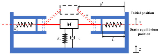
Figure 2.
The model of the quasi-zero stiffness passive vibration control mechanism.
The displacement from the static equilibrium position is x, and the spring restoring force F is expressed as:
By ignoring the higher-order terms of the Taylor expansion of Equation (1) at x = 0, the elastic recovery force is approximated as Fa:
The static equilibrium point is selected as the origin of the mass block, and the displacement coordinate directions of the controlled mass block and the base are shown in the figure. The system is subjected to a harmonic excitation of where Z represents the excitation amplitude and ω the frequency; the differential equation of motion is established as:
Let y = x − z; Equation (3) can then be transformed into a relative motion differential equation:
By introducing the following dimensionless parameters and substituting them into Equation (4) as follows:
We obtain:
The harmonic balance method is considered one of the most powerful methods capable of handling strongly nonlinear behaviors, and is an effective approximate method in frequency-amplitude analysis of nonlinear problems. It uses a truncated Fourier series representation, and can always converge to an accurate periodic solution for smooth nonlinear systems. This method can be applied to nonlinear oscillatory systems where the nonlinear terms are not small and no perturbation parameter is required. The motion differential Equation (5) can be solved using the harmonic balance method [22], with the steady-state response of the equation set as:
where A represents response amplitude and θ represents the initial phase.
The amplitude–frequency characteristics of the quasi-zero stiffness passive vibration control system are given as:
The amplitude–frequency characteristic diagram given by Equation (7) is illustrated in Figure 3.
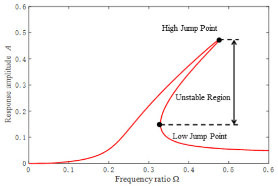
Figure 3.
The amplitude–frequency characteristic diagram.
It can be seen that in a certain frequency range the system presents multiple steady-state solutions, and there is a jumping phenomenon as well. The jumping phenomenon includes upward jumping and downward jumping. The frequency of upward jumping is related to system parameters, and the frequency of downward jumping can be approximately regarded as the resonant frequency point corresponding to the maximum amplitude of steady-state response.
2.2. Analysis of Displacement Transmissibility
The absolute displacement transmissibility of the passive vibration control system is defined as the ratio of the absolute amplitude of the mass block to the base response:
Through analysis of the absolute displacement transmissibility of the passive vibration control system, it can be known that the variation of stiffness can reduce the natural frequency of the system; however, the resonance cannot be avoided. It is necessary to adjust the damping of the system after selecting the most appropriate stiffness ratio in order to eliminate the resonance.
Based on previous research, we provide the main structural parameters of the passive vibration control system with quasi-zero stiffness and the amplitude of external excitation in Table 1.

Table 1.
Simulation Parameters.
3. Active Control Strategy
Based on the static analysis of the influence of damping variation on the absolute displacement transmissibility of the system, the vibration suppression capacity was optimized through introduction of an active control strategy.
3.1. Sliding Mode Control
The sliding mode variable structure control method is a special kind of nonlinear control of discontinuity. It is different from other controls in which the control structure is variable in that it can dynamically force the system to move along the predetermined sliding mode state trajectory constantly according to the variation of the system state. An SMC (sliding mode control) strategy based on reaching law is proposed in order to further improve the vibration suppression effect.
The SMC is added to the passive vibration control system; the motion differential equation with the added control item can be expressed as:
where and .
According to Equation (9), the corresponding state equation of the system is given by:
where and .
An approaching law control method is adopted; the sliding surface is usually designed as:
where is the system state and its derivatives. The system in this study belongs to the second-order system; thus, n = 2:
The select parameter ci () must satisfy the requirement that the polynomial be Hurwitz stable where p is the Laplace operator; thus, , let . The control algorithm is then derived as:
where slaw stands for the approaching law, and an exponential approaching law is used, that is:
where and .
The Lyapunov direct method is used to determine the stability of the sliding mode surface designed based on reaching law:
The sliding mode surface is stable.
Substitute Equations (10) and (13)–(15) into Equation (9) to obtain the control law:
where
Due to the use of the sign function sgn(s) in the SMC controller, chatter exists in the control force. The saturation function sat(s) is used instead of a sign function to attenuate the chatter:
where δ represents the threshold value, . When the threshold value is exceeded by s, switching control is adopted. While s is within the threshold value, linearized feedback control is adopted. The SMC law is revised as:
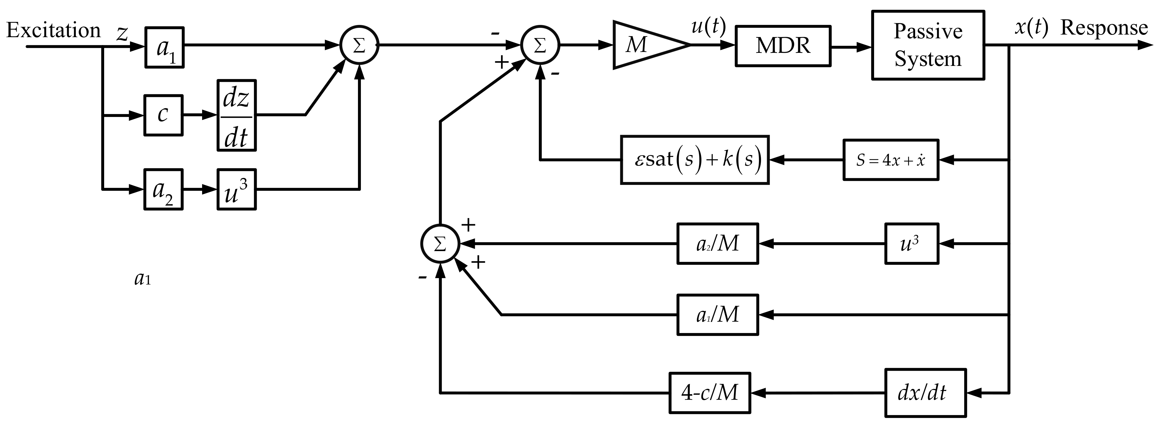
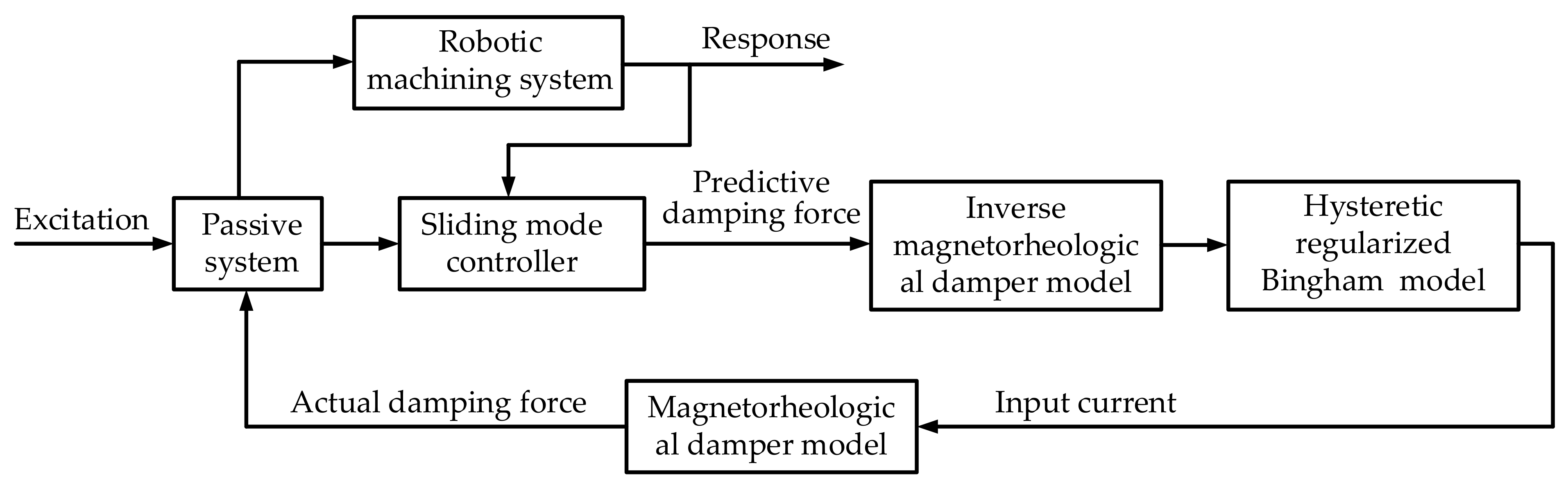
The control architecture is shown in Figure 4. The performance of the SMC vibration control system is simulated under several external excitations of different frequencies, and is compared with a passive vibration control system and the PID control method.
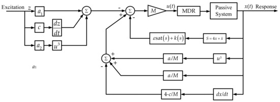
Figure 4.
The control architecture of the SMC.
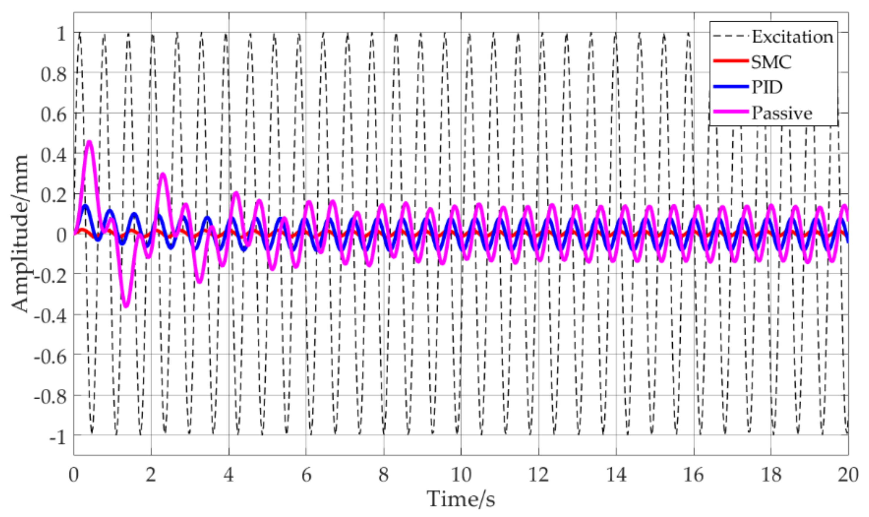
As shown in Figure 5, under the excitation of a sinusoidal signal with an amplitude of 1 mm and a frequency of 1 rad/s, the passive system is not yet effective in vibration control, while the active system has an obvious vibration suppression effect. The response amplitude is reduced by 35% with the PID control method and by more than 90% in the SMC when compared with the excitation amplitude.
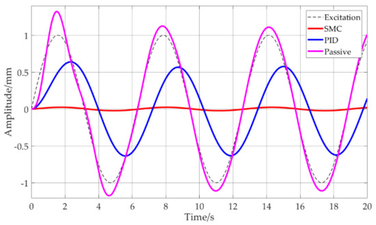
Figure 5.
Comparison of the SMC, PID and the passive system under excitation of a sinusoidal signal with an amplitude of 1 mm and a frequency of 1 rad/s.
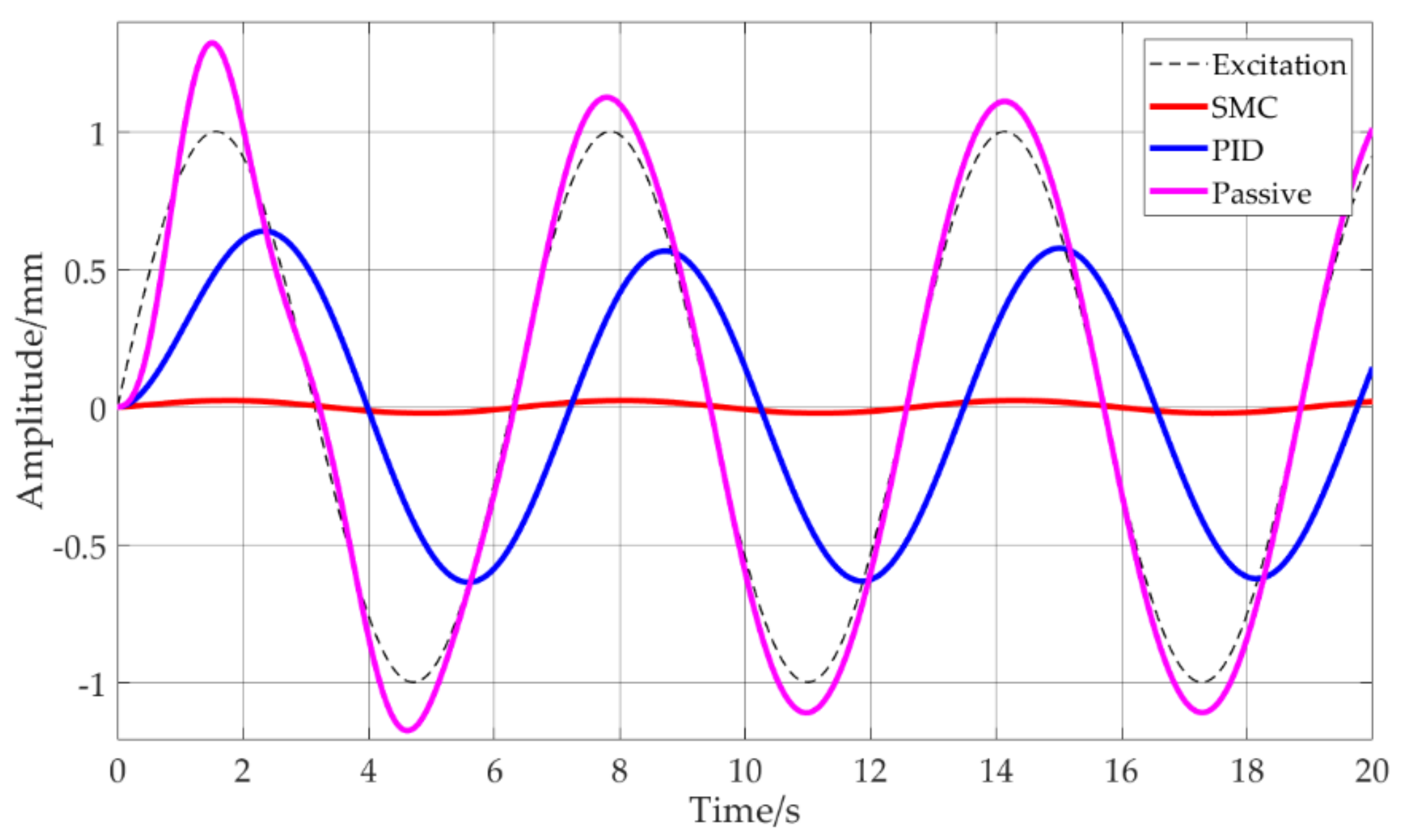
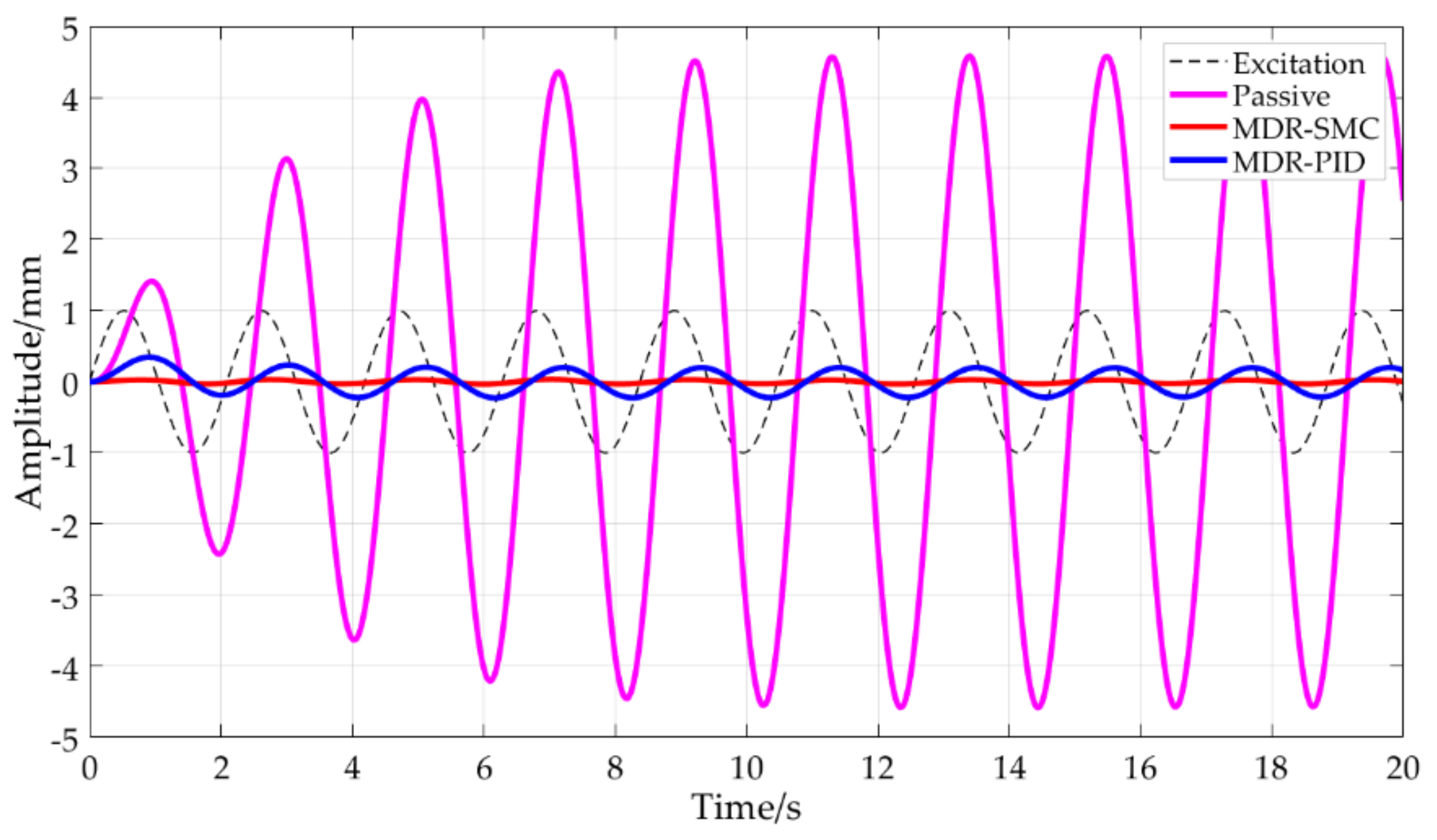
Figure 6 shows the comparison of the performance of the SMC, PID and the passive vibration control system under the excitation of a sinusoidal signal with an amplitude of 1 mm and a frequency of 3 rad/s by simulation.
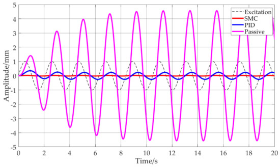
Figure 6.
Comparison of the SMC, PID and the passive system under excitation of a sinusoidal signal with an amplitude of 1 mm and a frequency of 3 rad/s.
Because 3 rad/s is the natural frequency of the quasi-zero stiffness vibration control system, the passive vibration control system has resonance, the maximum peak value is about 4.5 mm, and it is 4.5 times the excitation amplitude, which will have a great impact on the system. The response amplitude of the PID control is about 0.25 mm, which is 75% lower than that of the excitation. While the response amplitude of the SMC is about 0.02 mm, which is about 98% lower than that of the excitation, the vibration suppression effect is significant.
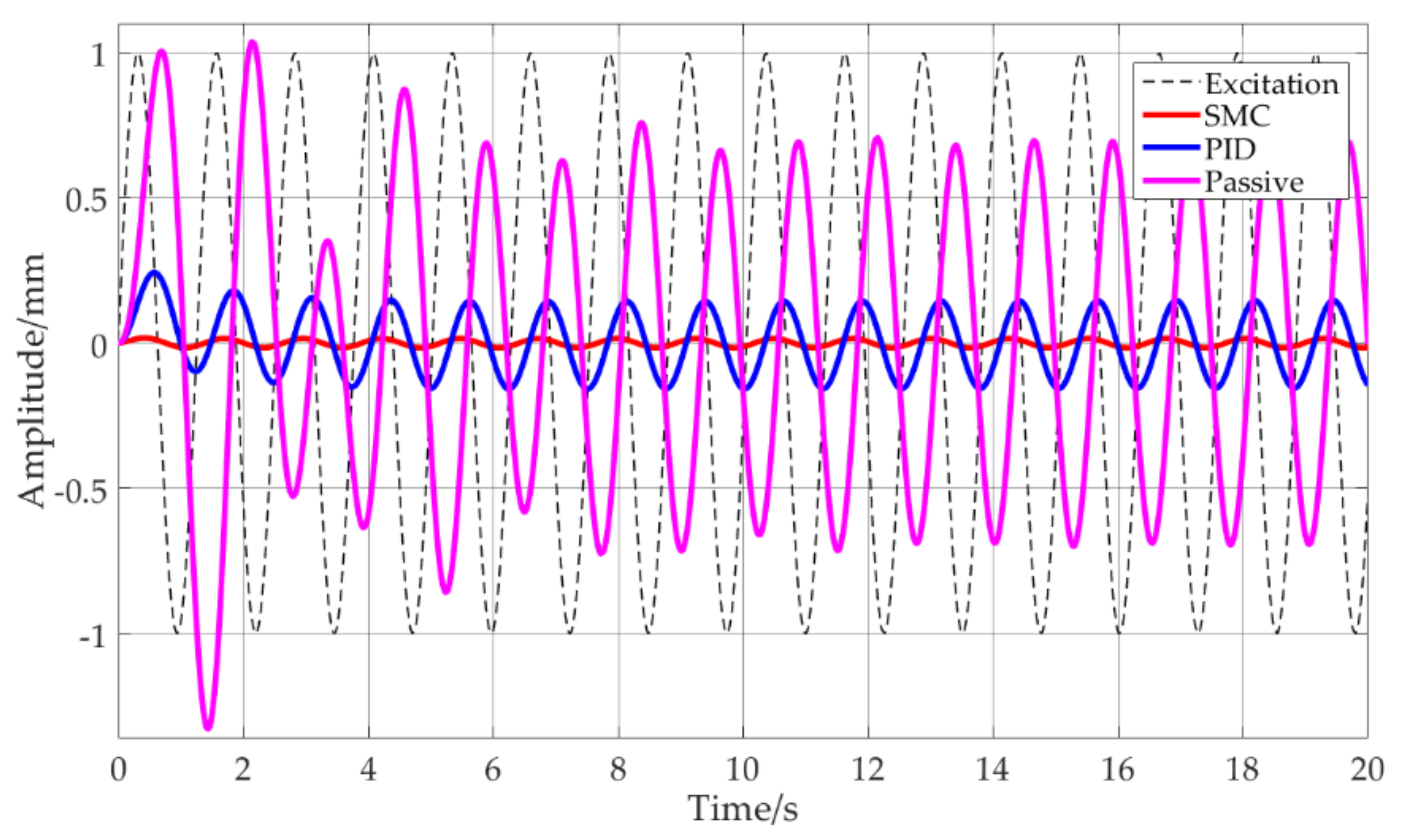
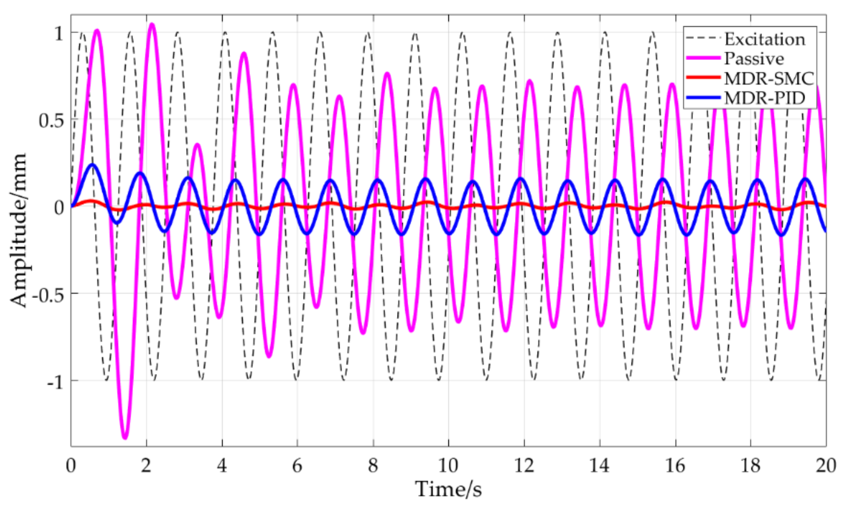
Figure 7 shows the results of a simulated comparison of the performance of the SMC, PID and the passive vibration control system under the excitation of a sinusoidal signal with an amplitude of 1 mm and a frequency of 5 rad/s. The passive system comes into play with inconspicuous effect. The response amplitude of the PID control is reduced by about 80%, while that of the SMC is reduced significantly.

Figure 7.
Comparison of the SMC, PID and the passive system under excitation of a sinusoidal signal with an amplitude of 1 mm and a frequency of 5 rad/s.
Figure 8 shows the comparison of the performance of the SMC, PID and the passive vibration control system under the excitation of a sinusoidal signal with an amplitude of 1 mm and a frequency of 10 rad/s. With the increase of excitation frequency, the response amplitude of the passive vibration control system obviously decreases, and is moderately identical with that of the active vibration control system.

Figure 8.
Comparison of the SMC, PID and the passive system under excitation of a sinusoidal signal with an amplitude of 1 mm and a frequency of 10 rad/s.
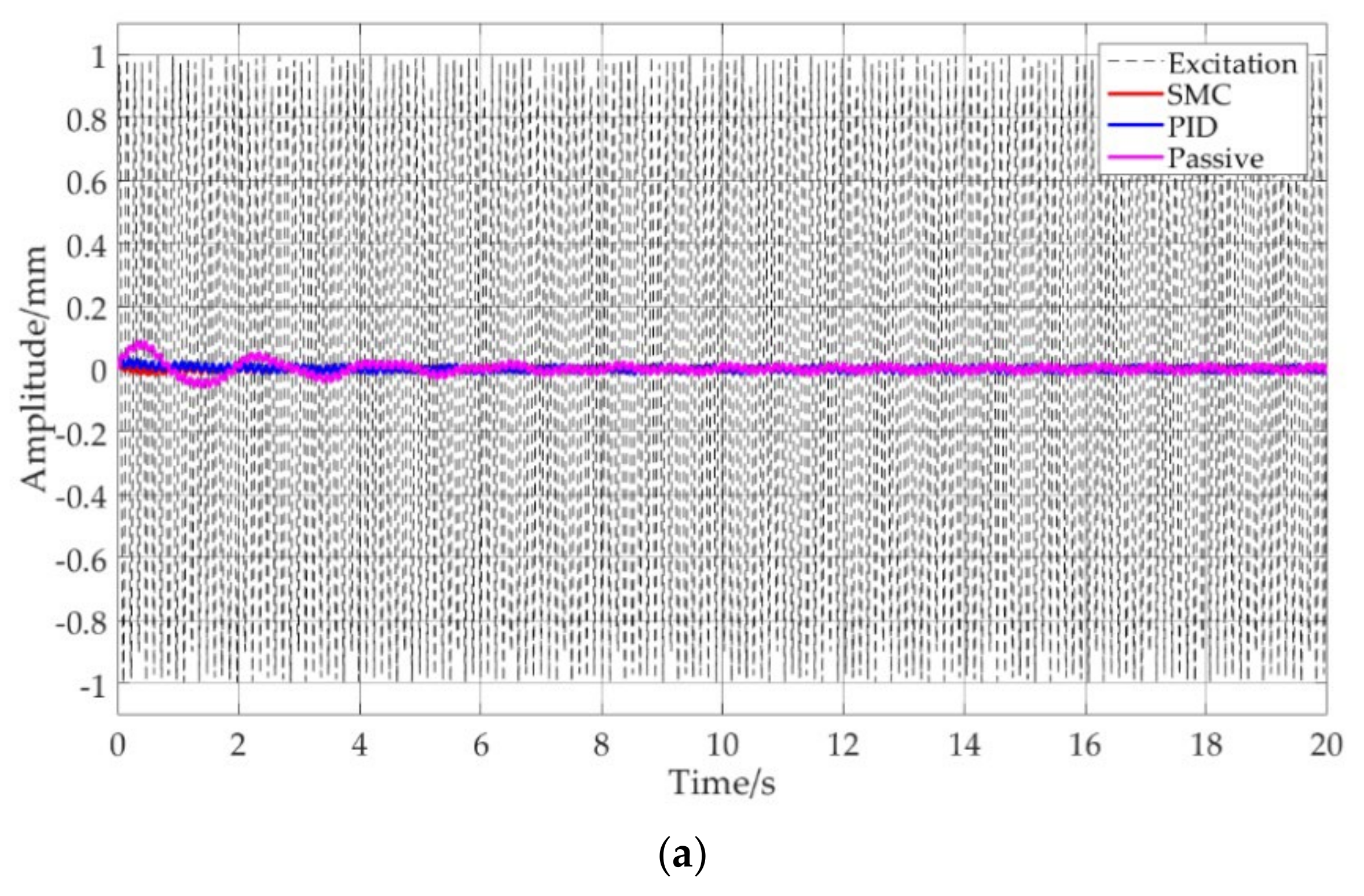
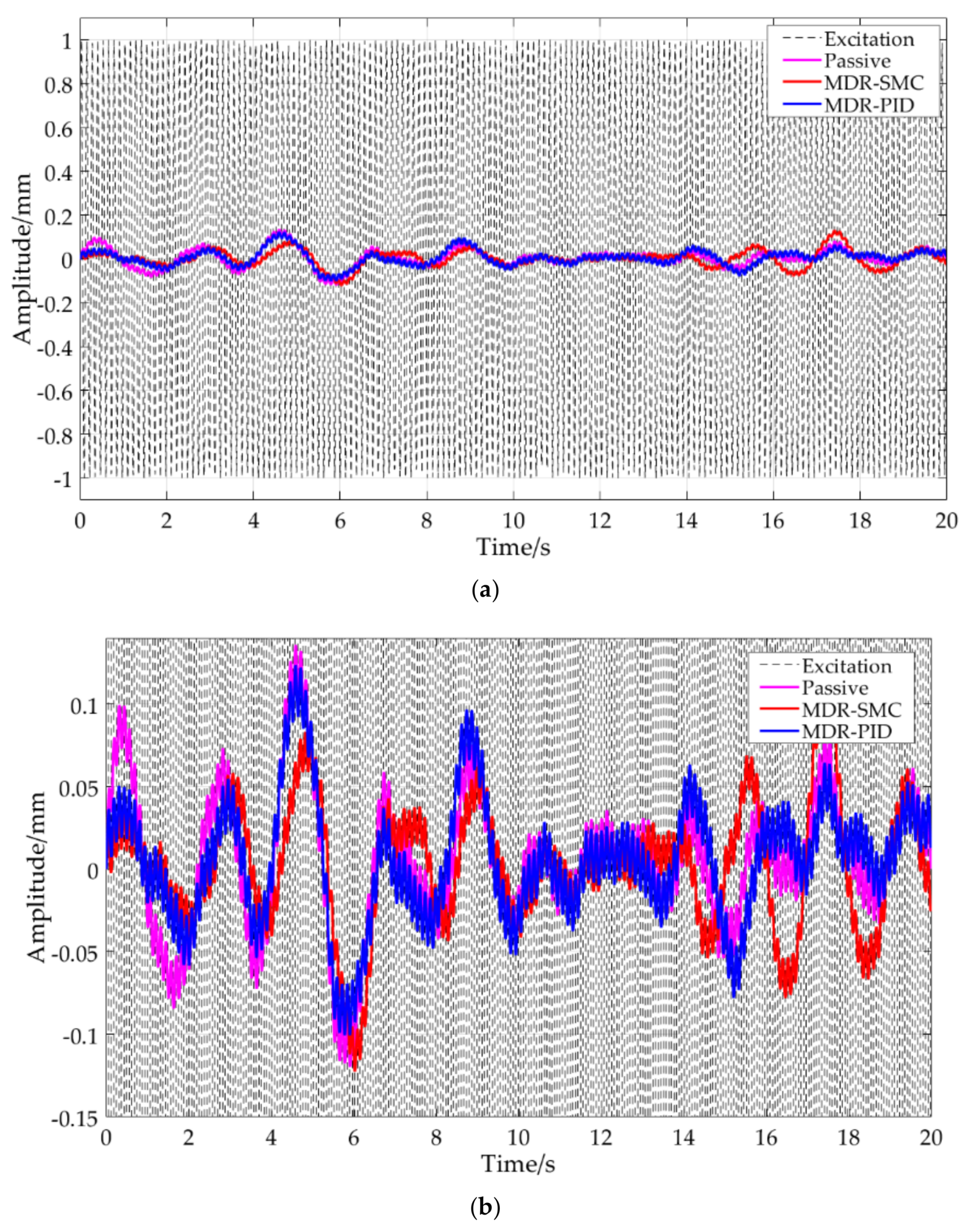
Figure 9 shows the comparison of the performance of the SMC vibration control system under the excitation of a sinusoidal signal with an amplitude of 1 mm and a frequency of 50 rad/s. Because the excitation frequency is higher than times the natural frequency of the equivalent linear passive system, the three vibration control methods are all significantly effective. The response amplitude is about 0.02 mm, which reduces 98% of the excitation amplitude and achieves an apparent vibration control effect.
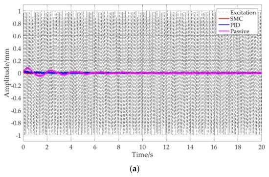
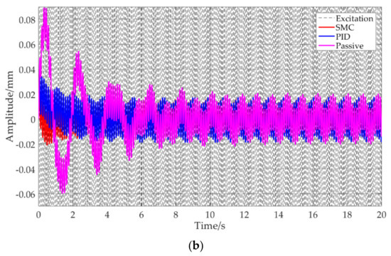
Figure 9.
Comparison of the SMC. PID and the passive system under excitation of a sinusoidal signal with an amplitude of 1 mm and a frequency of 50 rad/s (a) full figure (b) partial enlarged detail.
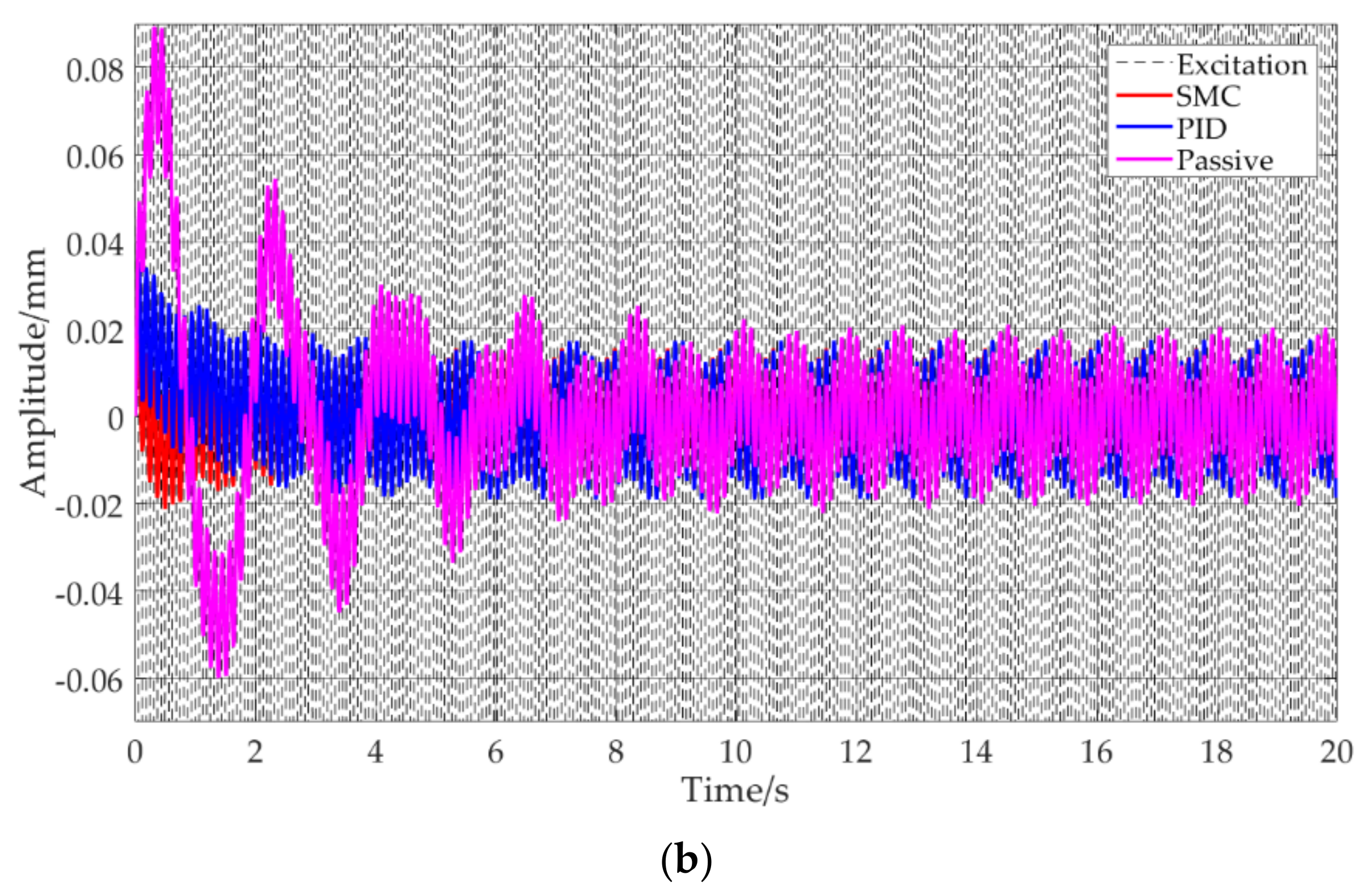
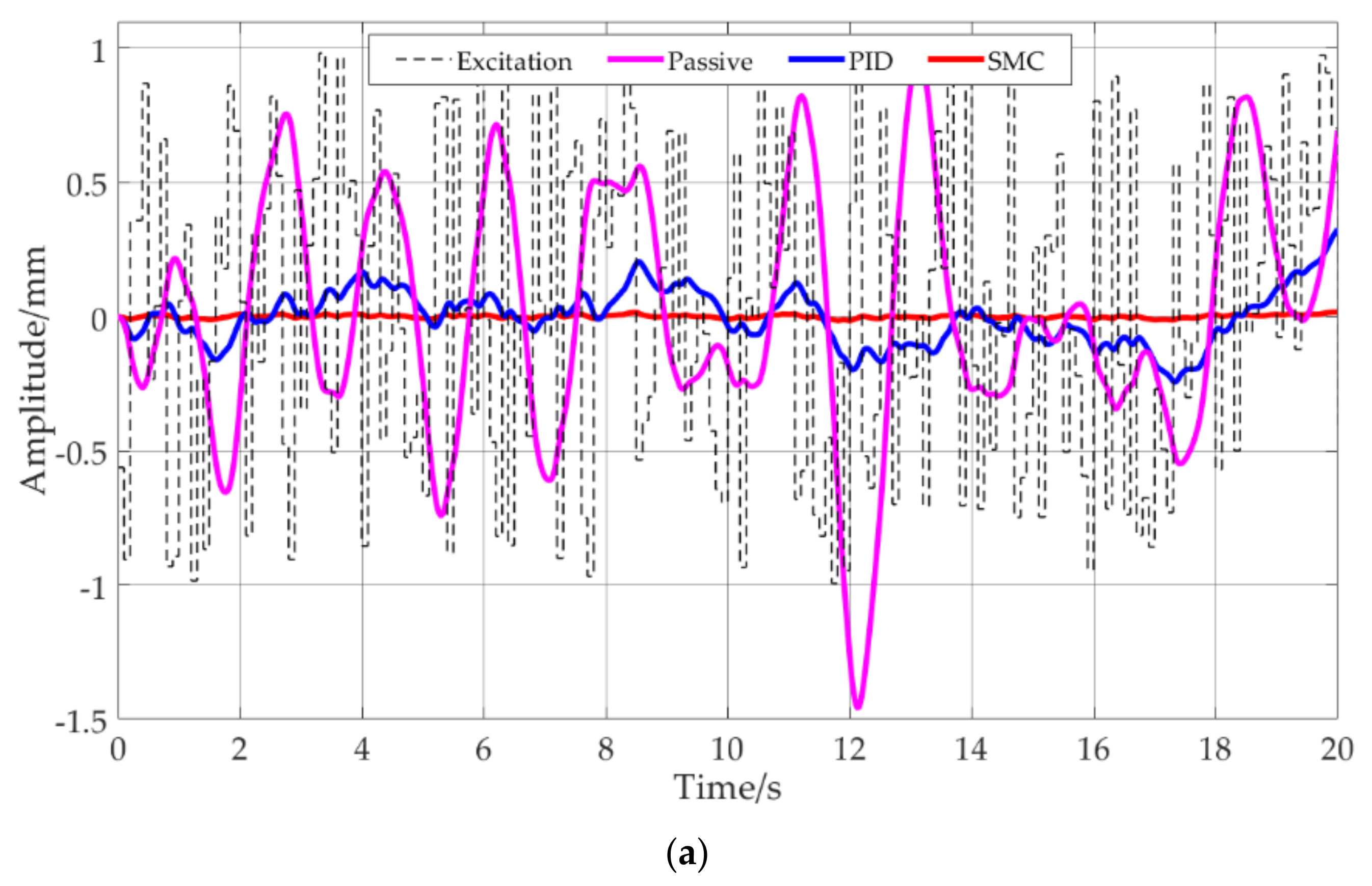
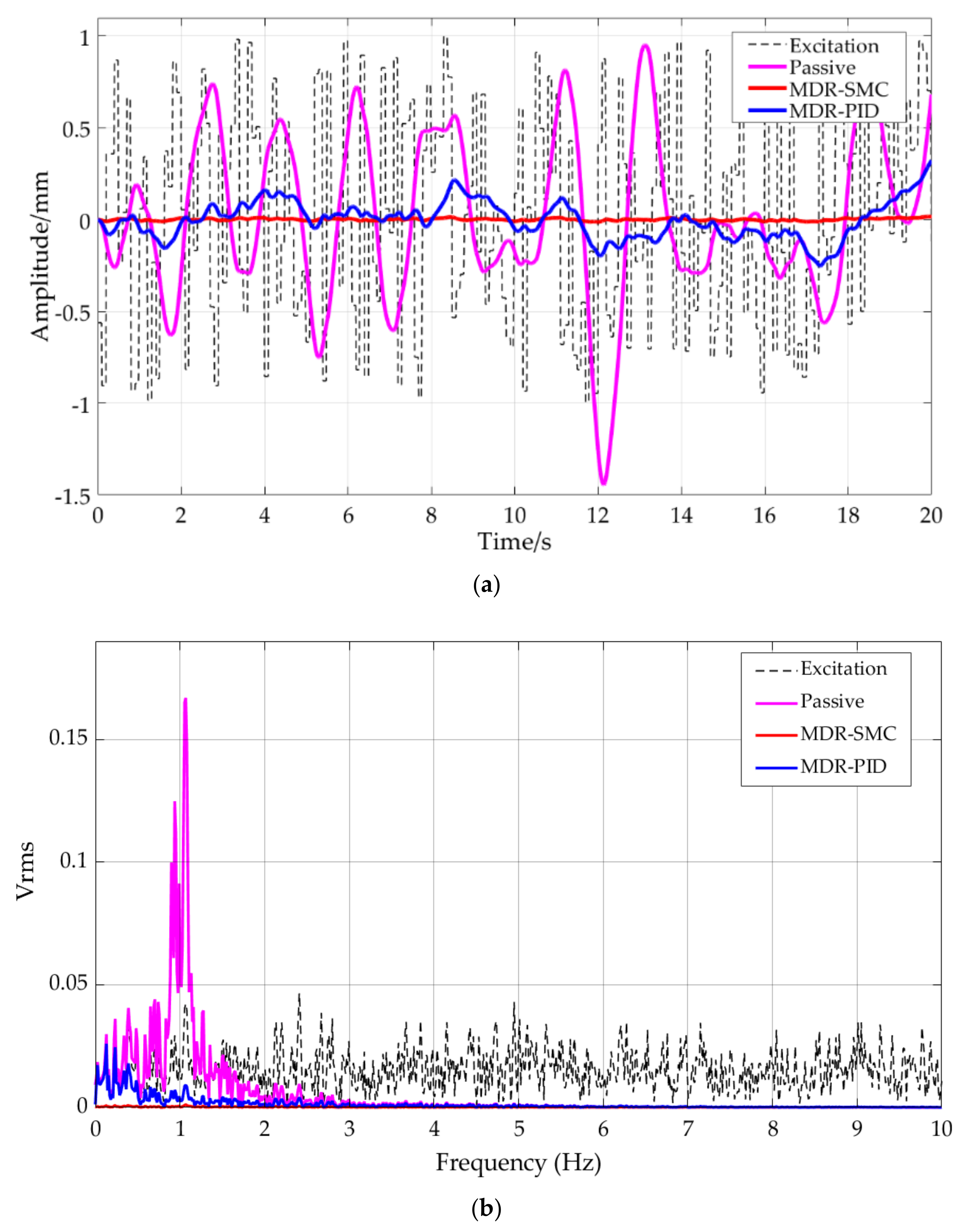
On the basis of the method in [23], a 50 s random excitation consisting of 200 normally distributed random numbers was constructed. The mean value and variance of the excitation were normalized to 0 and 1 respectively. This normally distributed random signal was set as the displacement excitation; the amplitude and frequency are random to some extent. The performance of the SMC vibration control system was simulated under such excitation and compared with the passive vibration control system and PID control. The time history of the random excitation and the response of the passive system, the PID control, and the SMC are shown in Figure 10a, and the spectrum of the excitation and the response are shown in Figure 10b.

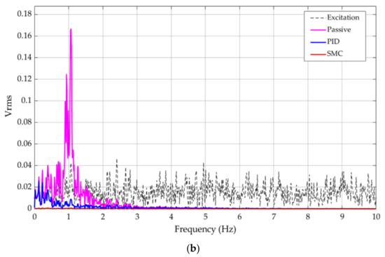
Figure 10.
Comparison of the SMC, PID and the passive system under normal distributed random signal: (a) time domain curve; (b) spectrum.
Although the passive system manifests vibration control in some periods, its response value is 1.4 mm at 12.3 s, which is 40% higher than the maximum value of the excitation. Both the SMC and PID exhibit better vibration control than the passive vibration control, among which SMC is more stable and always has a significant control effect.
In summary, the active control strategy has a certain degree of optimization effect on the quasi-zero stiffness passive vibration control system. Under low frequency excitation, the active control strategy can effectively avoid the resonance and achieve better vibration control. Moreover, the SMC vibration control system is distinctly superior to the PID vibration control system.
3.2. Active Control with a Magnetorheological Damper
A magnetorheological damper (MRD) has the advantages of large controllable range, robust controllability and fast response. A mixed type of flow shear linear MRD was adopted to provide the control force. According to the form of the piston rod, an MRD usually has two forms, single rod and double rod, among which the mechanism of the double rod damper is relatively simple. Without the restriction of stroke, the piston movement does not cause volume change in the cylinder, which meets the amplitude requirements of the ambient vibration in an aircraft assembly plant. A shear hybrid dual-rod MRD is proposed here in combination with the vibration control mechanism designed in [22] in order to improve active vibration control. The parameters are listed in Table 2, and a 3D model is shown in Figure 11. The prototype of the active vibration control mechanism with MRD is shown in Figure 12.
Table 2.
The parameters of the MRD.
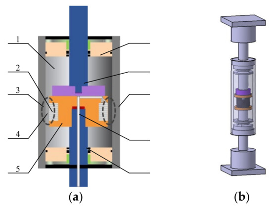
Figure 11.
A mixed type of flow shear linear MRD: (a) structure diagram; (b) prototype.
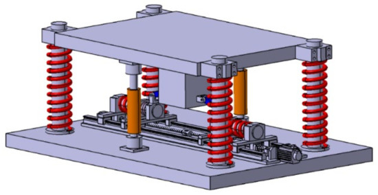
Figure 12.
The prototype of the active vibration control mechanism with MRD.
The damping force of the MRD is expressed by Equation (21):
The relationship between yield strength and control current is:
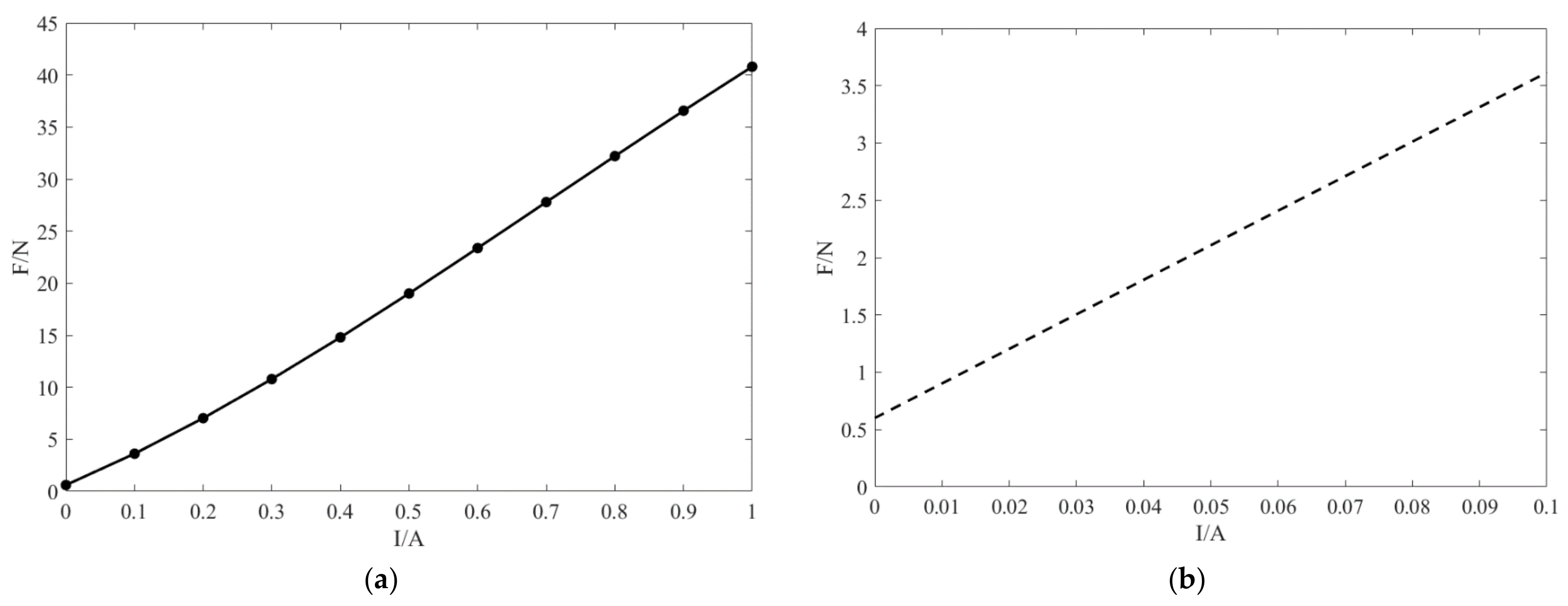
Under the condition that the piston moving speed is 1 mm/s, the corresponding current-damping force curve is obtained as shown in Figure 13. The damping force range is 0.6–40 N when the current is between 0 and 1 A, which can meet the requirements of the SMC controller.
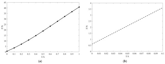
Figure 13.
Relationship between the current and damping force: (a) full figure; (b) partial enlarged detail.
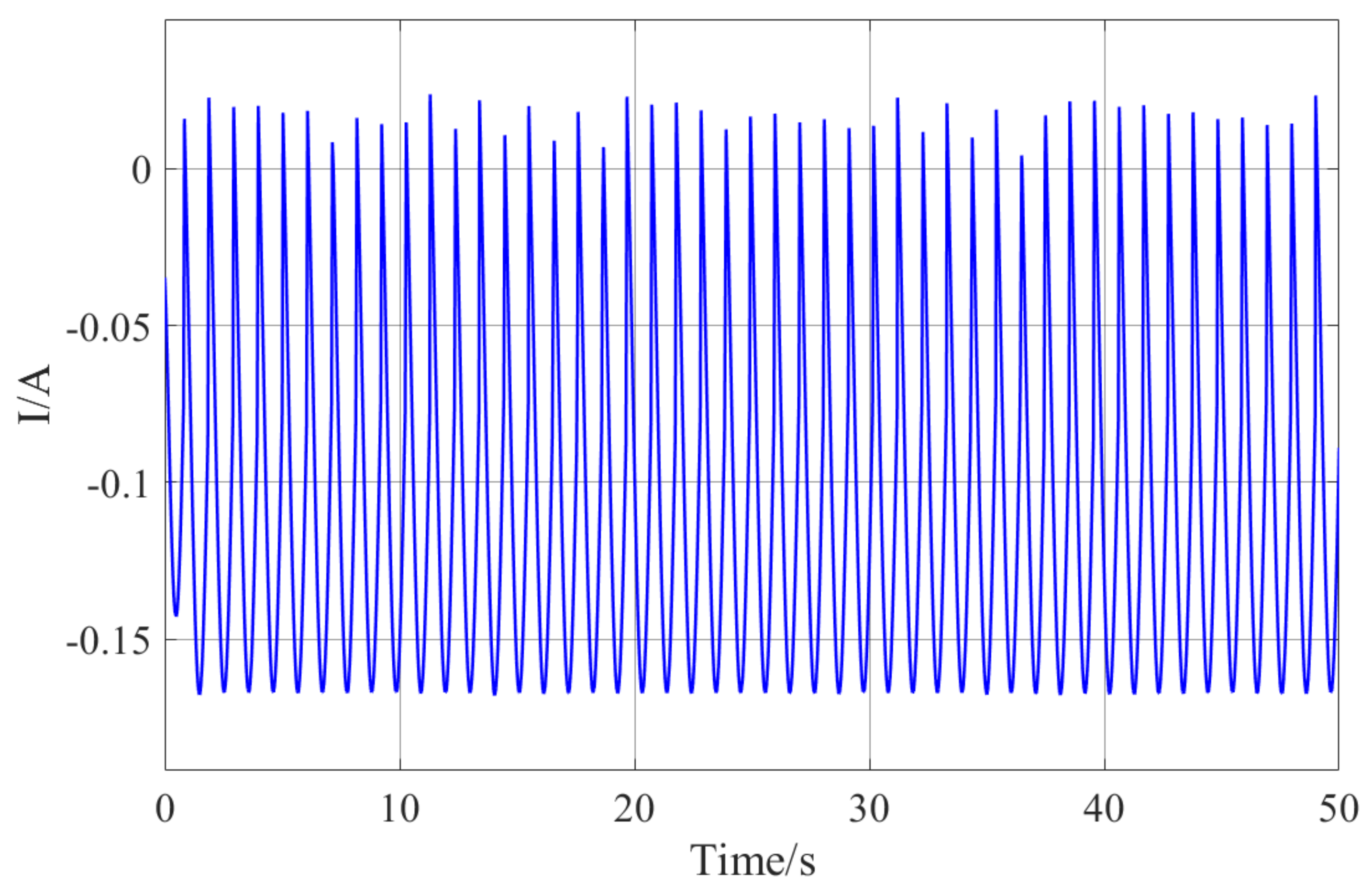
The control force of the SMC controller is a function of displacement and velocity, while the damping force provided by the MRD is a function of velocity and current. The control force of the SMC controller is provided by the MRD, i.e., F = u(t). Thus, the current corresponding to the control force can be obtained as an implicit function of control force and speed. The current required by the damping force of the MRD under low-frequency sinusoidal excitation is obtained by solving the unitary cubic equation. The current of the MRD under low-frequency sinusoidal excitation is shown in Figure 14.

Figure 14.
The current of the MRD under low-frequency sinusoidal excitation.
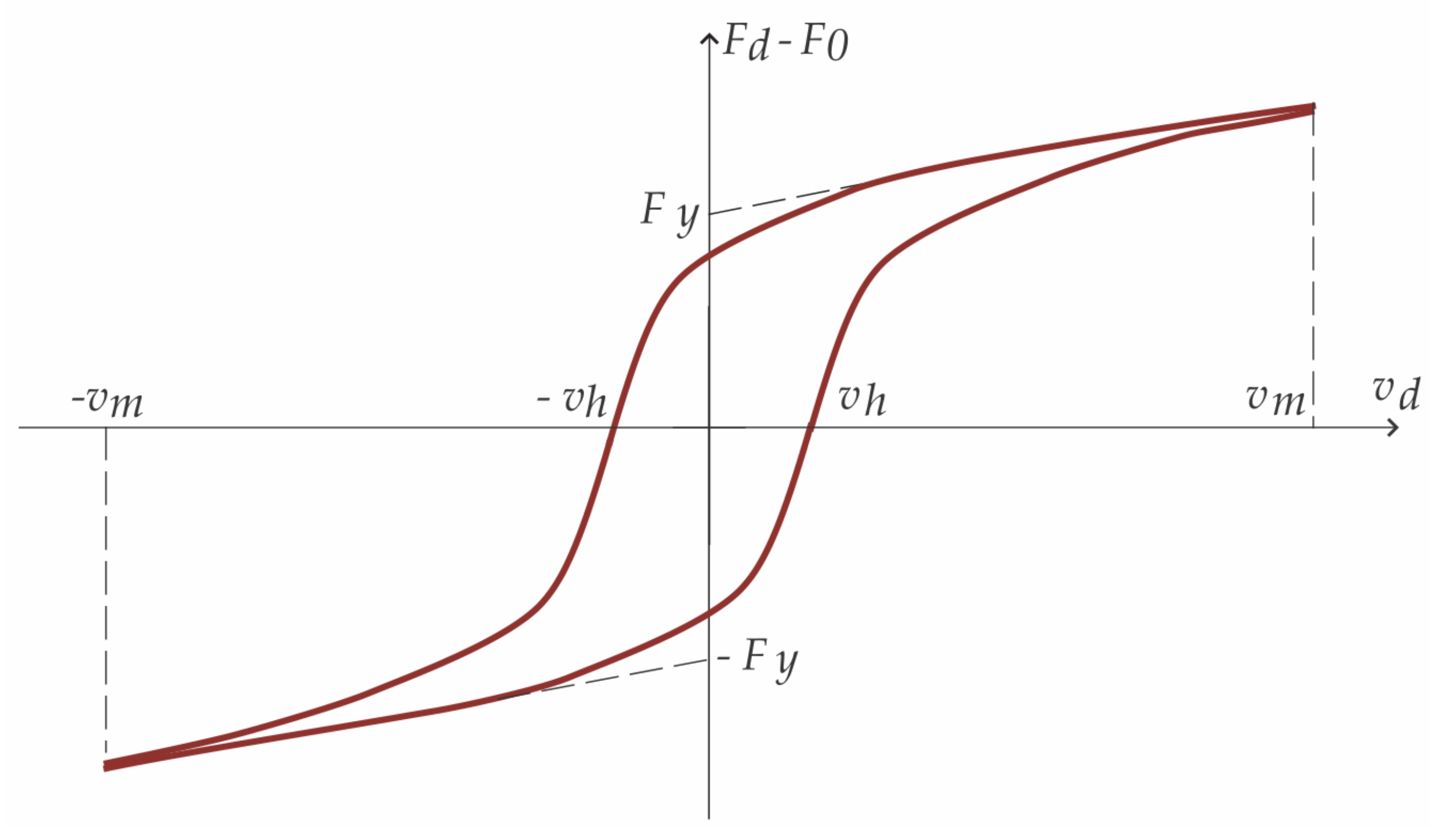
However, the MRD presents hysteretic characteristics [24,25,26], and the inherent nonlinear hysteresis of the MRD limits control precision and the response speed of the damping force. This is mainly due to hysteretic nonlinearity between the damping force and velocity, which is caused by the friction force and fluid compressibility in the damper as well as the nonlinear rheological characteristics of the magnetorheological fluid. The hysteretic nonlinearity between the damping force and velocity can be compensated for using a hysteretic dynamic model. The dynamic hysteretic regularized Bingham (HRB) model proposed in [27] and shown in Figure 15 is adopted in this paper where is the scale factor of the velocity (the range of which defines the width of the hysteresis ring) and represents the maximum velocity of the damper piston.
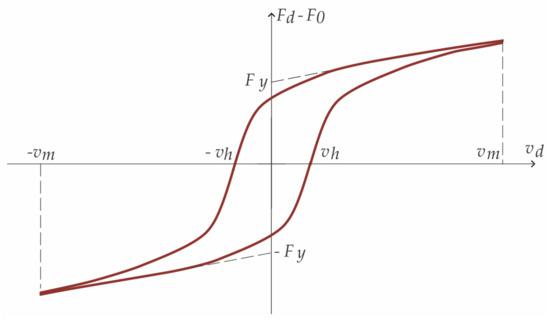
Figure 15.
The hysteretic regularized Bingham model (HRB).
4. Simulation
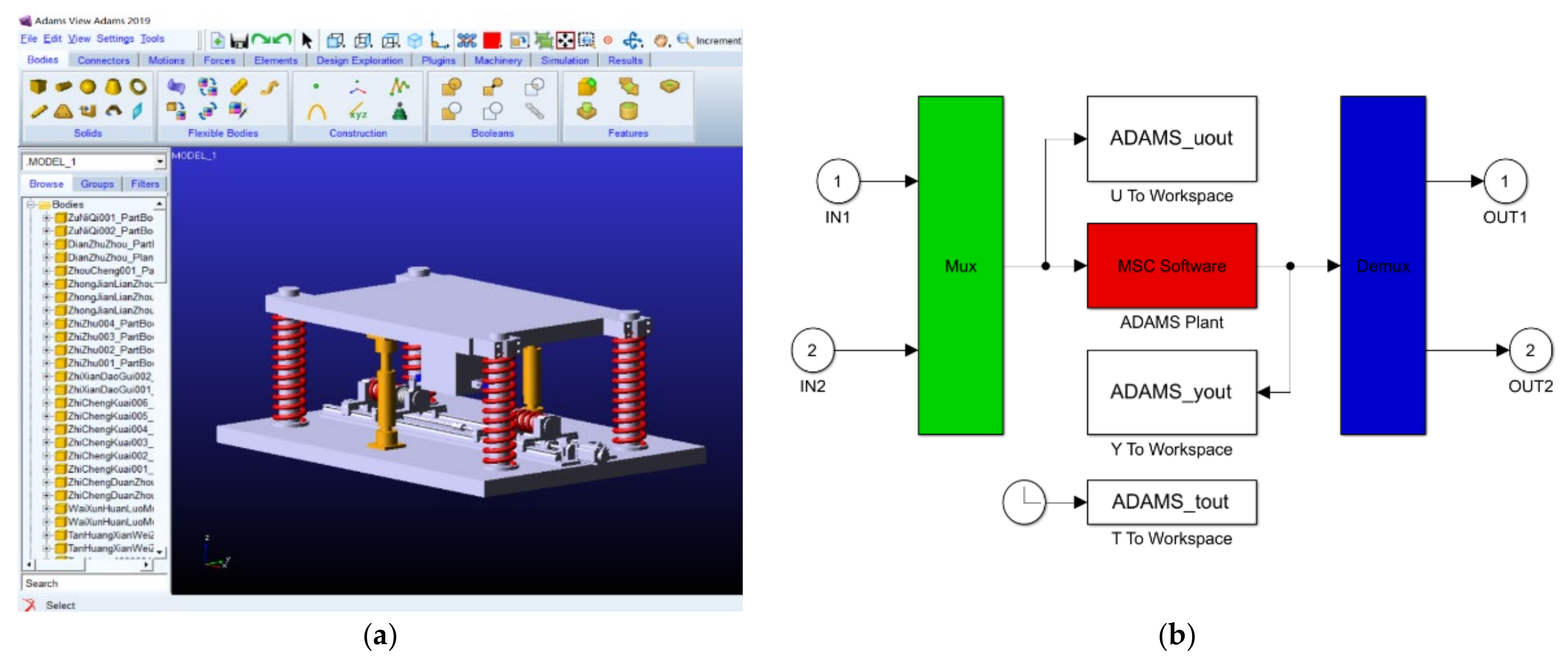
An ADAMS and MATLAB/Simulink co-simulation model was established as shown in Figure 16 in order to verify the optimization of the active vibration control system.

Figure 16.
ADAMS Simulation operation interface: (a) simulation model; (b) the interactive module Adams and Simulink.
The scheme of the control system is shown as Figure 17. The performance of the SMC vibration control system with MRD was simulated under several excitations of different frequencies by the co-simulation and compared with passive vibration control system and PID vibration control method.

Figure 17.
The scheme of the control system.
Figure 18, Figure 19, Figure 20, Figure 21 and Figure 22 show the performance comparison of the SMC vibration control system with MRD, the PID vibration control system with MRD, and the passive vibration control system under the excitations of the sinusoidal signal with an amplitude of 1 mm and different frequencies. The MDR-SMC in the figures represents the response amplitude of the SMC to excitation, and the MDR-PID the response amplitude of the PID controller. It can be seen that outside of the natural frequency the vibration control effect of the passive vibration control system constantly improves, and gradually tends to reach equivalence with that of the active vibration control system as the excitation frequency increases.
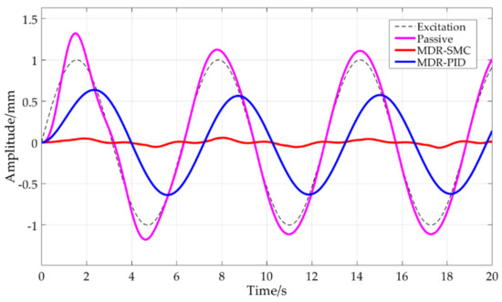
Figure 18.
Comparison of the SMC with MRD, PID with MRD, and the passive system under excitation of a sinusoidal signal with an amplitude of 1 mm and a frequency of 1 rad/s.
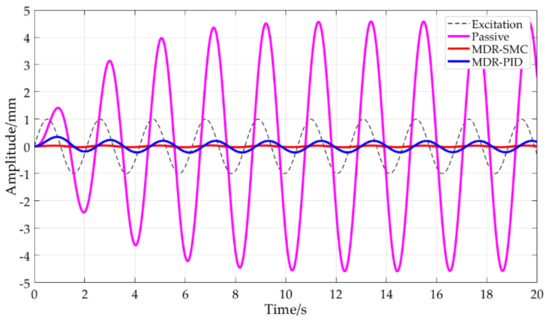
Figure 19.
Comparison of the SMC with MRD, PID with MRD, and the passive system under excitation of a sinusoidal signal with an amplitude of 1 mm and a frequency of 3 rad/s.
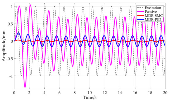
Figure 20.
Comparison of the SMC with MRD, PID with MRD, and the passive system under excitation of a sinusoidal signal with an amplitude of 1 mm and a frequency of 5 rad/s.
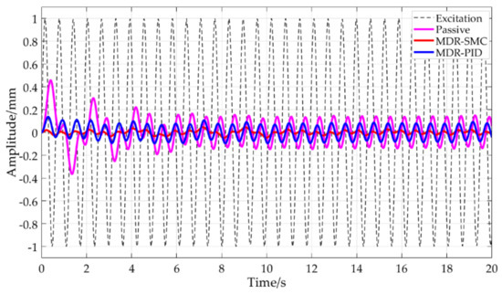
Figure 21.
Comparison of the SMC with MRD, PID with MRD, and the passive system under excitation of a sinusoidal signal with an amplitude of 1 mm and a frequency of 10 rad/s.
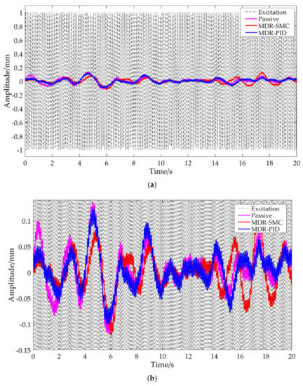
Figure 22.
Comparison of the SMC with MRD, PID with MRD, and the passive system under excitation of a sinusoidal signal with an amplitude of 1 mm and a frequency of 50 rad/s: (a) full figure; (b) partial enlarged detail.
Figure 23 shows the comparison by co-simulation of the performance of the SMC vibration control system with MRD, PID vibration control system with MRD, and the passive vibration control system under the same excitation with a normal distributed random signal as in Figure 10. The active control with MRD demonstrates effective vibration attenuation compared with the passive vibration isolation mechanism over a broad frequency range, and the SMC with MRD exhibits excellent suppression results compared with the PID control with MRD.

Figure 23.
Comparison of the SMC with MRD, PID with MRD, and the passive system under normal distributed random signal: (a) the time domain curve; (b) spectrum.
5. Conclusions
The amplitude–frequency characteristics and displacement transmissibility of the proposed passive vibration control system based on the quasi-zero stiffness mechanism for a robotic machining system were analyzed. A sliding mode active vibration control algorithm for ambient vibration during the robotic machining process was developed in order to dynamically improve the precision and efficiency of robotic machining. The active control force was obtained and optimized by simulation of the proposed SMC. An MRD and its structure parameters was designed according to the control force, and a sliding mode variable active vibration control system proposed using the MRD to provide the active control force.
A co-simulation model of Adams and MATLAB was established, and the feasibility of the active vibration control method verified by taking sinusoidal excitations with different frequencies and the random ambient excitation as the co-simulation input. Compared with the passive vibration control system, the response vibration amplitude under the active vibration control system was significantly reduced, especially with excitation frequencies close or equal to the natural frequency of the system. Compared with the PID control with MRD, the SMC with MRD presents excellent vibration attenuation performance, which verifies the effectiveness of the SMC with MRD approach. It can be concluded that the control strategy proposed in this article has a better damping effect and can improve the machining precision and stability of the robotic machining system.
The proposed active vibration control system and the SMC control strategy are by no means confined to the vibration isolation of robotic machining systems, and can be implemented in many practical engineering applications such as precision machine tools in assembly shops, vehicle on-board equipment, car seats, etc. An air spring with ideal nonlinear features could be introduced to further improve vibration control performance. In future research, deep learning algorithms could be used to increase adaptability with respect to the excitation frequency.
Author Contributions
Conceptualization and methodology, C.Z. and L.Z.; formal analysis, C.Z., F.Q. and M.W.; writing—original draft preparation, C.Z.; supervision, L.Z. and J.S.D.; Funding acquisition, L.Z. All authors have read and agreed to the published version of the manuscript.
Funding
This research was funded by the National Natural Science Foundation of China, grant number 51765031 and the Natural Science Foundation of Gansu Province, China, grant number 20JR5RA457.
Institutional Review Board Statement
Not applicable.
Informed Consent Statement
Not applicable.
Data Availability Statement
Not applicable.
Acknowledgments
The authors gratefully acknowledge the helpful comments and suggestions of the reviewers, which have improved the presentation.
Conflicts of Interest
The authors declare no conflict of interest.
Abbreviations
The abbreviations and symbols adopted throughout the paper are listed below.
| SMC | Sliding Mode Controller |
| QZS | Quasi-Zero Stiffness |
| MRD | Magnetorheological Damper |
| PD | Proportion Differentiation |
| PID | Proportion Integration Differentiation |
| FxLMS | Filtered-x Least Mean Square |
| LQR | Linear Quadratic Regulator |
| HRB | Hysteretic regularized Bingham |
| Kv (N/m) | The stiffness of the vertical spring |
| Kh (N/m) | The stiffness of the horizontal spring |
| c (N·s/mm) | The damping coefficient of the vertical damper |
| L0 (mm) | The initial length of the horizontal spring |
| L (mm) | The compressed length of the horizontal spring |
| a (mm) | The length of the connecting rod |
| d (mm) | The structural parameter |
| M (Kg) | The load mass (i.e., mass of the robotic machining system) |
| X (mm) | The displacement from the static equilibrium position |
| z (mm) | The amplitude of the harmonic excitation |
| Fa (N) | Approximate elastic restoring force of the system |
References
- Alabuzhev, P.; Gritchin, A.; Kim, L. Vibration Protecting and Measuring Systems with Quasi-Zero Stiffness; CRC Press: New York, NY, USA, 1989; pp. 10–54. [Google Scholar]
- Carrella, A.; Brennan, M.J.; Waters, T.P. Static analysis of a passive vibration isolator with quasi-zero stiffness characteristic. J. Sound Vib. 2007, 301, 678–689. [Google Scholar] [CrossRef]
- Carrella, A.; Brennan, M.J.; Waters, T.P.; Lopes, V., Jr. Force and displacement transmissibility of a nonlinear isolator with high-static-low-dynamic-stiffness. Int. J. Mech. Sci. 2012, 55, 22–29. [Google Scholar] [CrossRef]
- Li, Y.; Xu, D. Vibration attenuation of high dimensional quasi-zero stiffness floating raft system. Int. J. Mech. Sci. 2017, 126, 186–195. [Google Scholar] [CrossRef] [Green Version]
- Sun, Y.; Gong, D.; Zhou, J.S.; Sun, W.J.; Xia, Z.H. Low frequency vibration control of railway vehicles based on a high static low dynamic stiffness dynamic vibration absorber. Sci. China Technol. Sci. 2019, 62, 60–69. [Google Scholar] [CrossRef]
- Zhao, Z.M.; Wei, K.; Ren, J.J.; Xu, G.F.; Du, X.G.; Wang, P. Vibration response analysis of floating slab track supported by nonlinear quasi-zero-stiffness vibration isolators. J. Zhejiang Univ.-Sci. A 2021, 22, 16. [Google Scholar] [CrossRef]
- Zhai, X.; Luo, Y.J.; Zhang, Y.H.; Xie, S.L. Fuzzy PD hybrid control of low frequency vibration of annular antenna. Proc. Inst. Mech. Eng. G J. Aerosp. Eng. 2021, 235, 718–726. [Google Scholar] [CrossRef]
- Chen, L.J.; Che, B.H.; Huang, Y.; Zhu, M.G.; Yang, T.J.; Zhong, C.W. Active Vibration Control Mrthod for Test Model in Low Speed Wind Tunnel. J. Nanjing Univ. Aeronaut. Astronaut. 2021, 53, 7. [Google Scholar] [CrossRef]
- Giorgio, I.; Vescovo, D.D. Energy-based trajectory tracking and vibration control for multilink highly flexible manipulators. Math. Mech. Complex Syst. 2019, 7, 159–174. [Google Scholar] [CrossRef] [Green Version]
- Wang, J.M.; Kong, Y.F.; Huang, H. Cooperative control for vibration isolation and suppression based on Stewart platform. J. Vib. Shock 2019, 38, 9. [Google Scholar] [CrossRef]
- Wang, C.X.; Xie, X.L.; Chen, Y.H.; Zhang, Z.Y. Investigation on active vibration isolation of a Stewart platform with piezoelectric actuators. J. Sound Vib. 2016, 383, 1–19. [Google Scholar] [CrossRef]
- Yi, S.C.; Yang, B.T.; Meng, G. Microvibration isolation by adaptive feedforward control with asymmetric hysteresis compensation. Mech. Syst. Signal Process. 2019, 114, 644–657. [Google Scholar] [CrossRef]
- Wen, R.W. Micro Vibration Isolation Technology for Large Precision Instrument System Based on the Principle of Active Negative Stiffness. Doctoral Thesis, Harbin Institute of Technology, Harbin, China, March 2015. [Google Scholar]
- Sun, X.Q.; Yang, B.T.; Zhao, L.; Sun, X.F. Optimal design and experimental analyses of a new micro-vibration control payload-platform. J. Sound Vib. 2016, 374, 43–60. [Google Scholar] [CrossRef]
- Pan, G.Y.; Ghen, L.; Li, D.; Xiao, W.Q. Active isolation unit for the micro-vibration control. J. Vib. Shock 2018, 37, 227–230+261. [Google Scholar] [CrossRef]
- Han, C.; Choi, S.B.; Lee, Y.S.; Kim, H.T.; Kim, C.H. A new hybrid mount actuator consisting of air spring and magneto-rheological damper for vibration control of a heavy precision stage. Sens. Actuator A Phys. 2018, 284, 42–51. [Google Scholar] [CrossRef]
- Ma, T.; Bi, F.R.; Wang, X.; Tian, C.F. Optimized Fuzzy Skyhook Control for Semi-Active Vehicle Suspension with New Inverse Model of Magnetorheological Fluid Damper. Energies 2021, 14, 1674. [Google Scholar] [CrossRef]
- Li, G.; Ruan, Z.Y.; Gu, R.H.; Hu, G.L. Fuzzy Sliding Mode Control of Vehicle Magnetorheological Semi-Active Air Suspensio. Appl. Sci. 2021, 11, 10925. [Google Scholar] [CrossRef]
- Zhang, N.; Zhao, Q. Back-Stepping Sliding Mode Controller Design for Vehicle Seat Vibration Suppression Using Magnetorheological Damper. J. Vib. Eng. Technol. 2021, 1–18. [Google Scholar] [CrossRef]
- Zhao, Y.L.; Alashmori, M.; Bi, F.R.; Wang, X. Parameter identification and robust vibration control of a truck driver’s seat system using multi-objective optimization and genetic algorithm. Appl. Acoust. 2021, 173, 107697. [Google Scholar] [CrossRef]
- Liu, X.H.; Wang, N.N.; Wang, K.; Huang, H.; Li, W.H. Optimizing Vibration Attenuation Performance of a Magnetorheological Damper-Based Semi-active Seat Suspension Using Artificial Intelligence. Front. Mater. 2019, 6, 269. [Google Scholar] [CrossRef]
- Zhang, L.X.; Zhao, C.M.; Qian, F.; Dhupia, J.S.; Wu, M.L. A Variable Parameter Ambient Vibration Control Method Based on Quasi-Zero Stiffness in Robotic Drilling Systems. Machines 2021, 9, 67. [Google Scholar] [CrossRef]
- Shen, Y.J.; Wang, L.; Yang, S.P.; Gao, G.S. Nonlinear dynamical analysis and parameters optimization of four semi-active on-off dynamic vibration absorbers. J. Vib. Control 2012, 19, 143–160. [Google Scholar] [CrossRef]
- Sessa, S.; Vaiana, N.; Paradiso, M.; Rosati, L. An inverse identification strategy for the mechanical parameters of a phenomenological hysteretic constitutive model. Mech. Syst. Signal Process. 2020, 139, 106622. [Google Scholar] [CrossRef]
- Gołdasz, J.; Sapinski, B.; Jastrzębski, Ł. Assessment of the Magnetic Hysteretic Behaviour of MR Dampers through Sensorless Measurements. Shock. Vib. 2018, 2018, 3740208. [Google Scholar] [CrossRef]
- Arias-Montiel, M.; Floreán-Aquino, K.H.; Francisco-Agustín, E.; Piñón-López, D.M. Experimental Characterization of a Magnetorheological Damper by a Polynomial Model. In Proceedings of the 2015 International Conference on Mechatronics, Electronics and Automotive Engineering (ICMEAE), Cuernavaca, Mexico, 24–27 November 2015. [Google Scholar] [CrossRef]
- Soltane, S.; Montassar, S.; Mekki, O.B.; Fatmi, R.E. A hysteretic Bingham model for MR dampers to control cable vibrations. J. Mech. Mater. Struct. 2015, 10, 195–206. [Google Scholar] [CrossRef]


Publisher’s Note: MDPI stays neutral with regard to jurisdictional claims in published maps and institutional affiliations. |
© 2022 by the authors. Licensee MDPI, Basel, Switzerland. This article is an open access article distributed under the terms and conditions of the Creative Commons Attribution (CC BY) license (https://creativecommons.org/licenses/by/4.0/).