Abstract
In order to improve the inflow state of the combined sluice-pumping station project with a 15° transverse side angle, a Y-shaped settling diversion wall is designed, which can change its layout form according to the operation conditions of the project. To analyze the flow characteristics of the Y-shaped settling diversion wall with different parameter combinations, an orthogonal test is used in this article. Considering four factors that can affect the flow pattern—the length, width, radian and arc radius of the diversion wall—the rectifying performances of 25 diversion wall schemes were analyzed under two operating conditions. The results show that the radian factor of the Y-shaped settling diversion wall has the greatest influence on its rectification effect. Finally, combined with numerical simulation of the optimal scheme and several other comparison schemes, the best scheme for the parameter combination of the diversion wall of the combined sluice-pumping station with a 15° transverse side angle is obtained.
1. Introduction
The combined sluice-pumping station is a kind of water conservancy project with joint arrangement of pump station and sluice. Due to its compact layout in space, short construction period and complementary functions between lock and pump station during its operation time, the combined sluice-pumping station has been widely used. However, due to the structural restrictions of the combined sluice-pumping station itself, when the sluice runs alone, the upstream flow is often inclined to one side, leading to the appearance of a large area of backflow and vortex in front of the sluice, thus reducing the discharge capacity of the sluice and even endangering the safety of the building [1,2]. When the pump station operates alone, the upstream flow will also be inclined to one side, causing serious backflow and oblique flow in the forebay, which will further lead to some adverse phenomena, such as vibration, cavitation and poor operation efficiency of the pump unit [3,4]. The bad inflow state will cause extremely adverse effects on the operation of the project, so the inflow state of the combined sluice-pumping station needs to be studied and solve the deviation problem caused by the transverse flow.
The authors of [5,6,7] mainly studied the hydraulic flow characteristics by model testing and numerical simulation and put forward a series of rectification measures that include a diversion pier, sill, column, water plate, etc. At the same time, with the development of computer technology, the accuracy of numerical simulation has been gradually improved, and the problems of the rectification of a large number of practical water conservancy projects have been solved by the method of numerical simulation [8,9,10,11]. Xu et al. [12] studied and analyzed the influence of the size of the diversion wall and the design of the perforated diversion wall on the navigable flow conditions of the combined sluice-pumping station by using the single factor variable analysis method. The results show that the navigable flow conditions are significantly affected by the design of the perforated diversion wall. Zhao et al. [13] studied the flow law in the forebay of the combined sluice-pumping station under the rectification measures of an arc diversion pier with a different radius of pier head through numerical simulation, and the best dimension parameters of the diversion wall were obtained. To solve the problem of transverse flow in the forebay of the pump station, previous studies show that the Y-shaped diversion pier has relatively good application benefits. Zhang et al. [14] conducted numerical simulation on the lateral inlet forebay with Y-shaped diversion piers. The results show that by arranging Y-shaped diversion piers in front of the inlet pool, the transverse flow can be significantly uniformed and the reflux area can be eliminated, which can make the water flow more evenly into each unit. Cheng et al. [15] quantitatively analyzed the influence of the position, height, angle and length of the Y-shaped diversion pier on the flow pattern of the forebay of the pump station by using FLUENT software, obtaining the optimal parameters of the Y-shaped diversion pier suitable for a single pump station, and reduced the bias flow phenomenon in the forebay during the operation of pumping. Xi et al. [16] proposed that the combined rectification measures formed by the perforated diversion pier, Y-shaped diversion pier and flow guide sill along the flow can better solve the problem of bias flow caused by transverse flow. However, for the combined sluice-pumping station with complex inlet conditions, previous studies mainly focus on the sluice or station rectification measures under a single working condition. There is still a lack of relevant research on whether the Y-shaped diversion wall has good application benefits in the combined sluice-pumping station and whether the change in its geometric parameters has an impact on the effect of rectification.
The main dimensional parameters of a Y-shaped diversion wall include the length, width, arc radian and height of the diversion wall, that is, there are many factors affecting its rectification effect. If the tests are carried out one by one, it will waste a lot of time and even be difficult to implement. The orthogonal test is a method of selecting some representative points from a comprehensive test by using mathematical principles for testing and analysis. Compared with the single factor variable method, the orthogonal test can greatly reduce the number of tests, and the best combination of test factors can be obtained by using the standardized orthogonal table to design the test plan, and then the range and variance of the test results can be analyzed to obtain the influence degree of each factor on the index [17]. Because of its convenient and scientific nature of orthogonal testing, it has been widely used in fluid mechanical engineering studies. Zhou et al. [18] analyzed the orthogonal test data, optimized the design scheme of the model pump, and obtained the influence law of the geometric parameters of the pump on its performance. Shi et al. [19] calculated the performance data of a gas–liquid mixed vane pump under each impeller size parameter scheme by using the orthogonal experimental design method of five factors and four levels. Yang et al. [20] adopted the orthogonal test scheme of three factors and four levels to optimize the structural size design of the drainage channel of the low specific speed centrifugal pump. Zhou et al. [17] used the orthogonal test scheme of four factors and four levels and the computational fluid dynamics method to analyze the flow characteristics of a diversion pier under different parameter combinations, obtaining the optimal value range of diversion pier size parameters of the lateral inlet pump station.
In order to explore whether the Y-shaped diversion wall has good application benefits in the combined sluice-pumping station and whether its geometric parameters have an impact on the rectification effect, a Y-shaped settling diversion wall is designed in this study, which is located between the sluice and the pump station, and it can change its layout according to the engineering operation conditions. By using the combination of the orthogonal test method and numerical simulation calculation, the inflow flow pattern of the combined sluice-pumping station with a 15° transverse side angle is studied under the conditions of self-draining and pumping, respectively. The geometric parameters of the diversion wall are designed by the orthogonal test method to determine the parameter combination scheme. Then, through the comparative analysis of the test results, the size of the diversion wall is optimized. Finally, by means of numerical simulation calculation, the results of the orthogonal test are compared with the results of other characteristic schemes to verify the rationality of the results of the orthogonal test and obtain the degree of the influence of various size parameters of the diversion wall on the inlet flow pattern of the combined sluice-pumping station.
2. Study Area and Method
2.1. Study Area
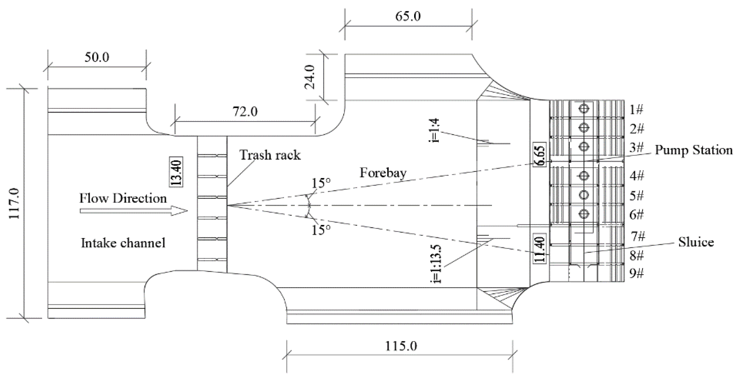
The layout of a combined sluice-pumping station includes one pump station and one sluice. The pump station is equipped with six pumps, and the sluice chamber is equipped with three gates. In order to ensure the accuracy of numerical simulation research and reduce the impact on the flow pattern simulation of forebay and sluice, due to the lack of upstream and downstream structures, a three-dimensional numerical calculation model of the combined sluice-pumping station is established, including the intake channel, slope section, sluice chamber section and inlet channel. At the same time, in order to facilitate research and analysis, the inlet channel is simplified and extended. The calculation model established is a typical asymmetric engineering layout of a combined sluice-pumping station with a total length of about 280 m and a maximum width of about 117.0 m, and its model scale is 1. Its calculation area is shown in Figure 1. The design flow of a single pump in the pump station is 30 m3/s, and the inlet channels of each pump are numbered as 1#, 2#, 3#, 4#, 5# and 6#, of which the 1# inlet channel is close to the left wall of the river diversion, the 6# inlet channel is close to the sluice, the elevation of the forebay and river bottom plate is 13.4 m, and the elevation of the bottom plate of the inlet pool is 6.65 m. The sluice chamber of the sluice is equipped with three gates, numbered 7#, 8# and 9#, of which the 7# sluice is close to the side of the pump station, the 9# sluice is close to the right wall of the river diversion, the elevation of the sluice floor is 11.4 m, and the middle between the sluice and the pump station is separated by a diversion wall. The main functions of the project are flood control and drainage, that is, the sluice is responsible for self-drainage and the pump station is responsible for pumping. When the pump station is running, the sluice is closed, taking the upstream water level of 21 m and the downstream water level of 24.3 m. When the sluice is opened, the pump station stops running, taking the upstream water level of 22.2 m and the downstream water level of 22.05 m. Figure 2 shows the layout plan of the combined sluice-pumping station. In this research, the transverse side angle refers to the included angle formed by the center line along the flow direction of the intake channel and the connecting line between the midpoint of the vertical flow direction at the inlet section of the forebay and the midpoint of the pump station or sluice on the layout plan. Both of the transverse side angles between the pump station and the sluice are 15°.
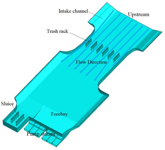
Figure 1.
Schematic diagram of calculation area.
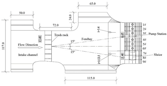
Figure 2.
Layout plan of the combined sluice-pumping station.
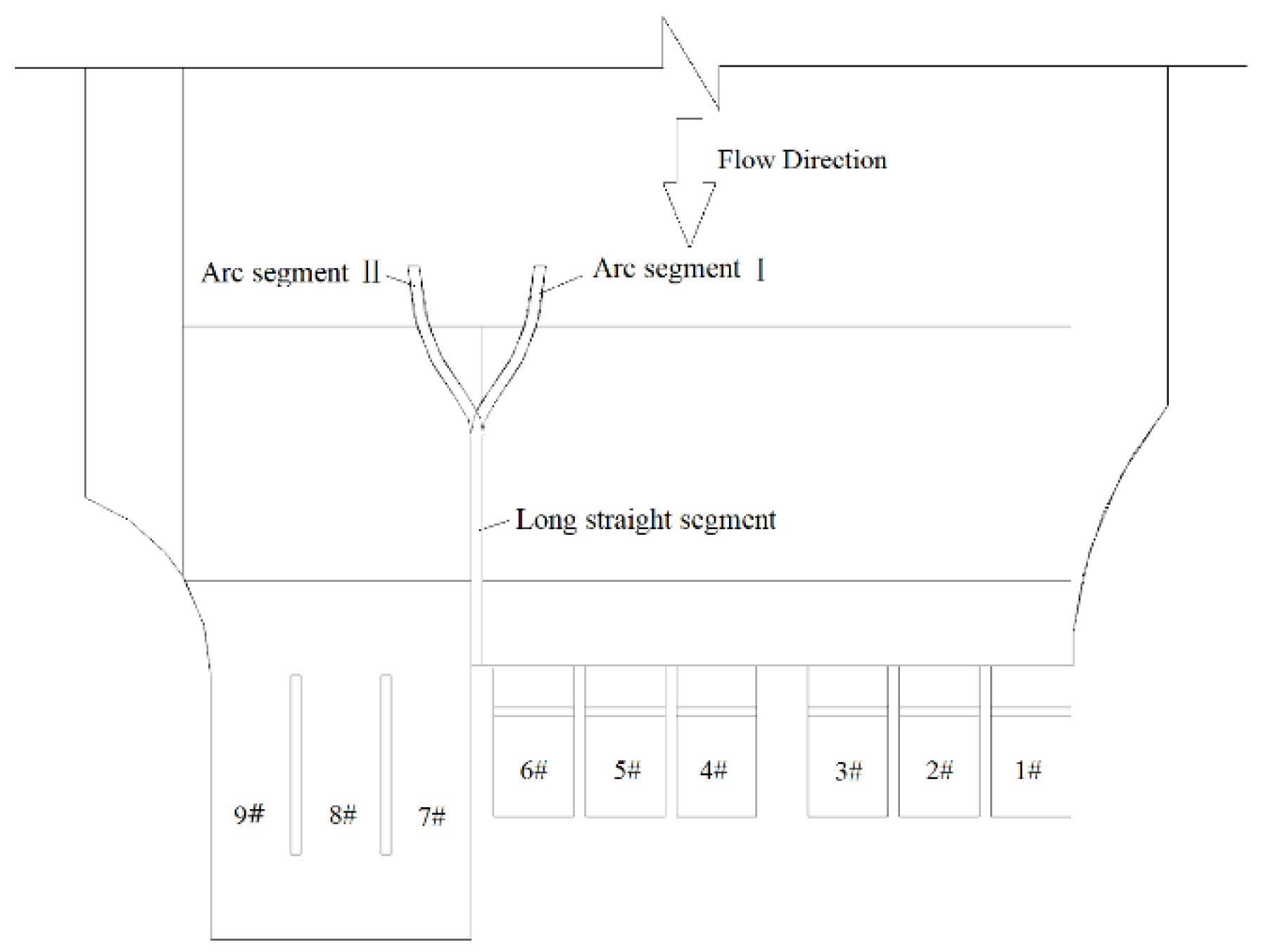
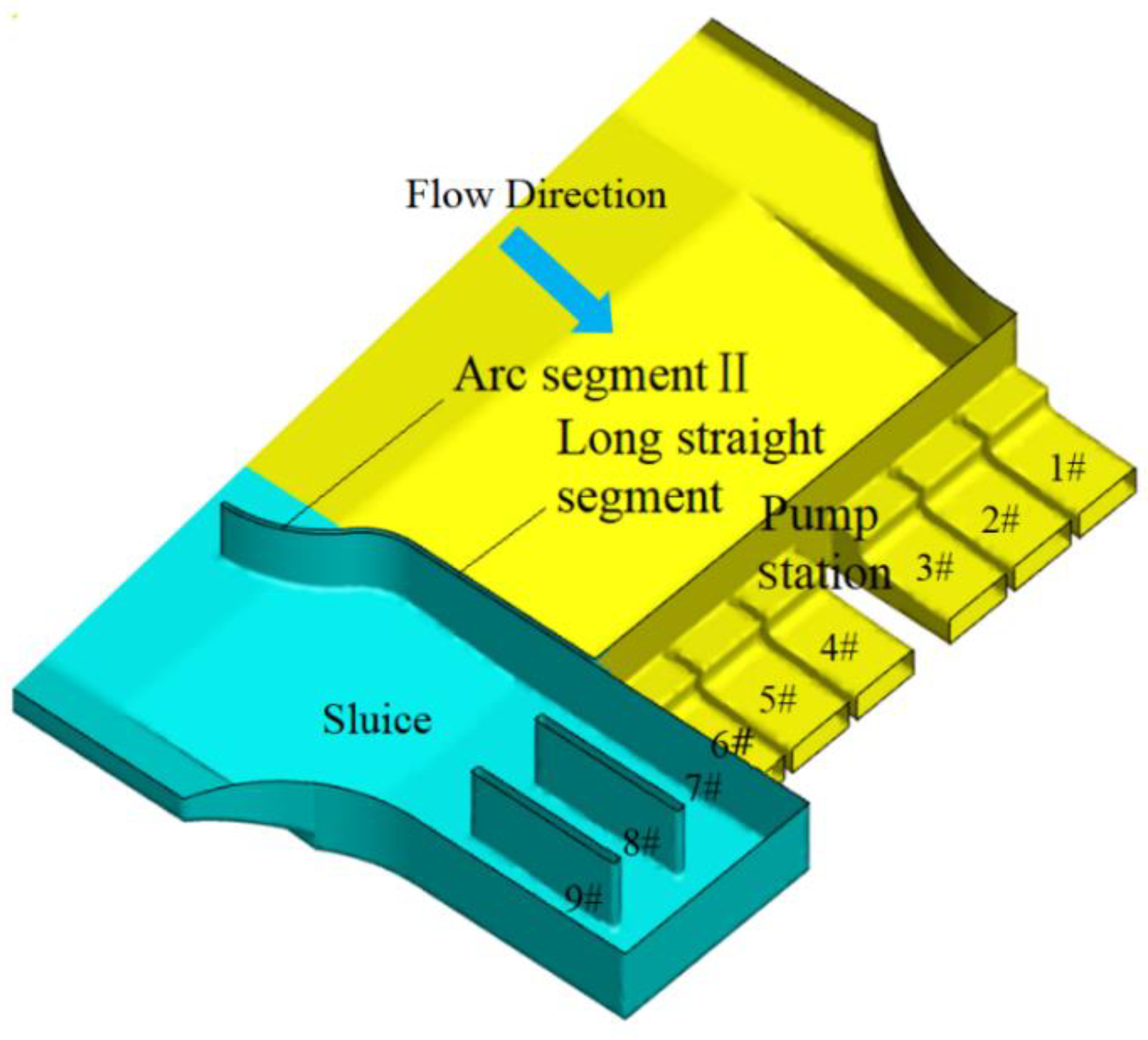
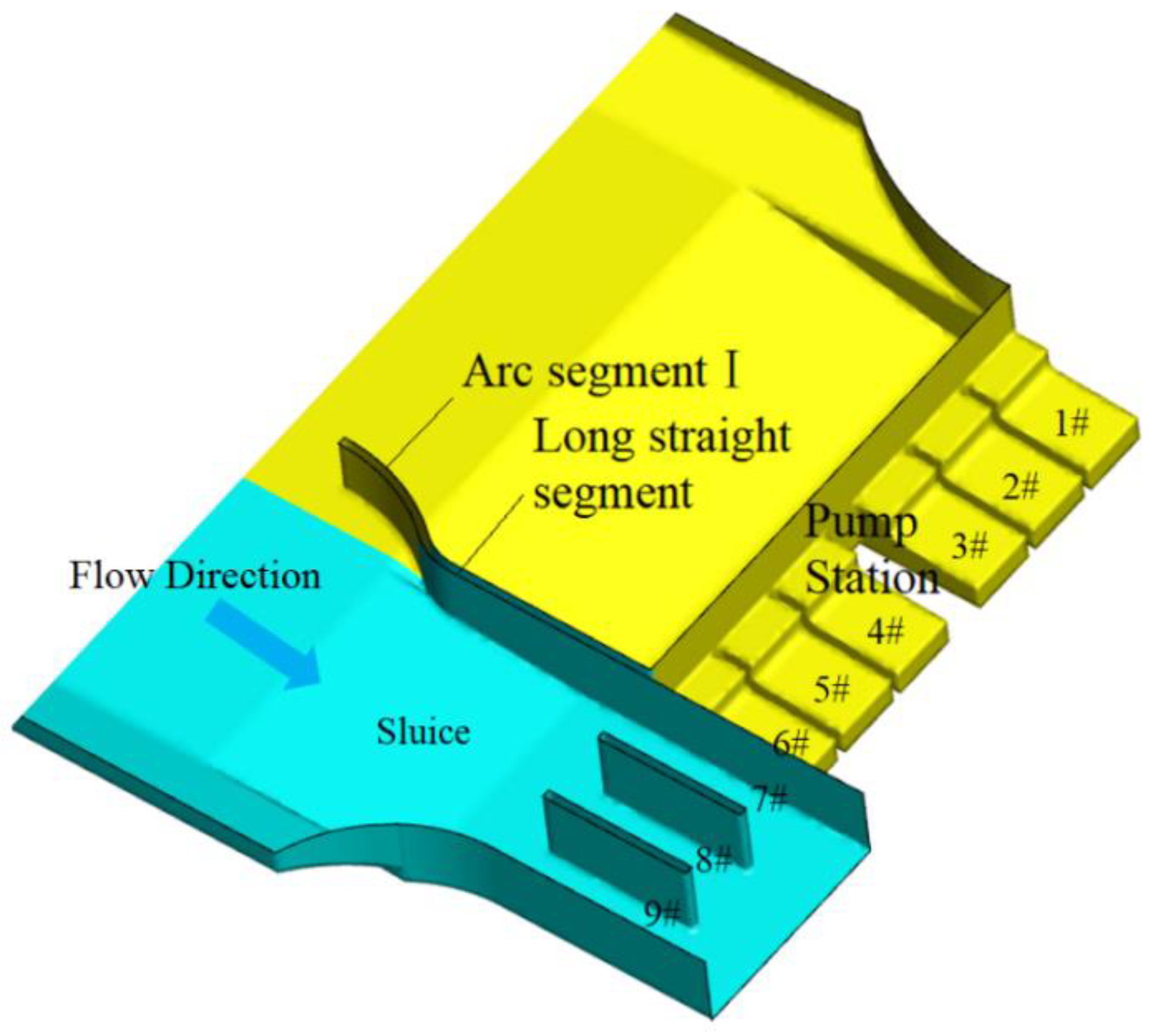
The proposed and studied diversion wall is shown in Figure 3. The Y-shaped settling diversion wall is set between the sluice and the pump station, which is mainly divided into a long straight segment, arc segment I and arc segment II. Under the condition of pumping, as shown in Figure 4, arc segment I will sink automatically until its top elevation is lower than the floor elevation of the forebay. Under the condition of self-draining, as shown in Figure 5, the arc section II will sink automatically until its top elevation is lower than the floor elevation of the sluice.
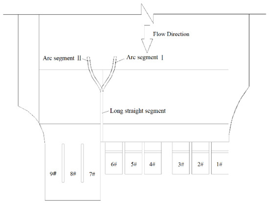
Figure 3.
Layout plan of the diversion wall.

Figure 4.
Three-dimensional layout of diversion wall (condition of pumping).

Figure 5.
Three-dimensional layout of diversion wall (condition of self-draining).
2.2. Study Method
2.2.1. Grid Division
In this paper, GAMBIT software is used to mesh the fluid calculation area. Due to fact that the geometric situation of the model is complex, tetrahedral element unstructured mesh with strong applicability is used [21]. Meanwhile, in order to ensure the calculation accuracy and reduce the calculation workload, it is necessary to carry out the independence analysis of the calculation grid [22]. Under the condition of pumping, the hydraulic loss from the river diversion to the inlet channel is taken as the characteristic parameter to determine the appropriate grid number. The calculation formula is shown in Equation (1):
where is hydraulic loss, m; is inlet static pressure, pa; is the outlet static pressure, pa; is the inlet speed, m/s; is the outlet speed, m/s.
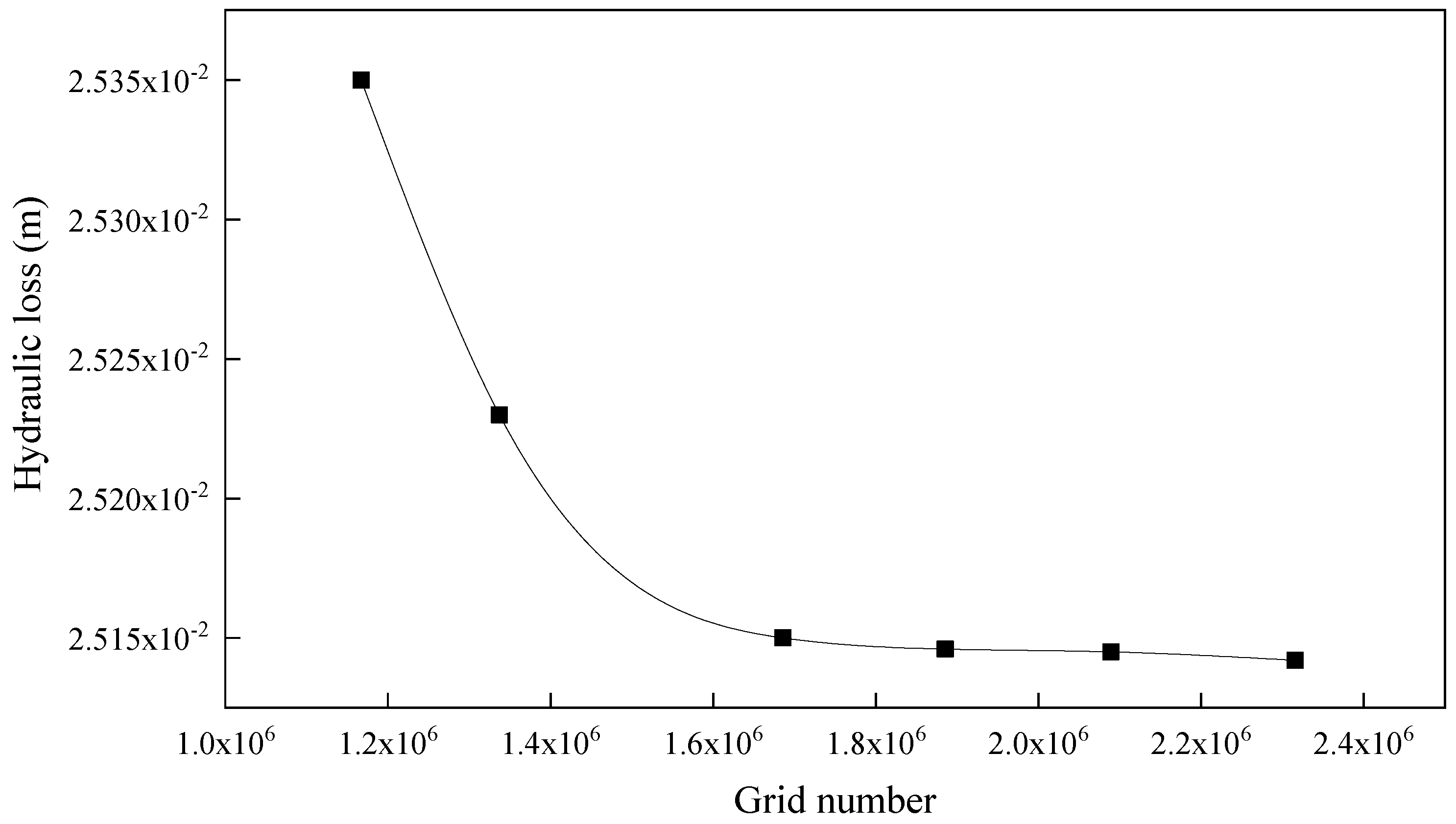
Figure 6 shows the hydraulic loss calculated by each grid number. The numbers of the grids are 1,167,278, 1,33,7082, 1,685,634, 1,885,461, 2,089,159 and 2,315,785. By a series of comparisons, it was found that when the number of grid exceeds 1,686,251, the hydraulic loss is basically unchanged, which can meet the requirements of grid independence. Under the condition of self-draining, the hydraulic loss from the river diversion to the sluice is taken as the characteristic parameter to determine the appropriate grid number. The calculation formula is also shown in Equation (1). After the independence analysis, the calculated grid number is less than that in the pumping and discharge condition, so the grid number 1,686,251 is also used under the condition of self-draining.
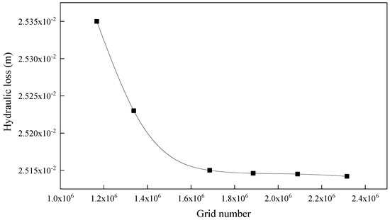
Figure 6.
Hydraulic loss under different grid numbers.
2.2.2. Boundary Condition
Under the operating condition of pumping, the speed inlet condition is adopted, and the inlet section of the diversion river is selected as the inlet boundary [23]. The outlet boundary is set at the inlet pool of the pump station, and the free outflow condition is also selected. Under the condition of self-draining, the inlet section of the approach river is still selected as the inlet boundary and the speed inlet condition is adopted, the outlet boundary is set at the sluice and the outlet section is extended to fully develop the water flow, and the outlet free outlet condition is also selected. The standard wall function is used for wall boundary treatment. The surface of the flow is a free water surface. Additionally, since the water surface changes little with time, the rigid cover assumption is adopted for the water surface, and the free surface is set to be symmetrical.
2.2.3. Turbulence Model
The fluid movement follows the three laws of mass conservation, momentum conservation and energy conservation. The intake water flow density of the combined sluice-pumping station is a constant, which can be regarded as a constant viscous and incompressible fluid, and the heat exchange capacity of the water flow can be ignored, so the energy equation is not considered [24]. The continuity equation and momentum equation obtained from the law of conservation of mass and the law of conservation of momentum are selected as follows:
where , are the flow velocity vectors in each direction, m/s; is the fluid density, kg/m3; , represent each coordinate axis; g is gravity acceleration, m/s2; is the static pressure of turbulent kinetic energy, pa; is the effective viscosity coefficient of the fluid; i and j are the vector direction.
In order to make the equations easy to solve, the K equation reflecting turbulent kinetic energy and the equation reflecting turbulent energy dissipation rate need to be introduced. At present, there are several models available for selection, including Standard k- model, RNG k- model and Realizable k- model [25,26]. Through comparative analysis and comprehensive consideration of schedule requirements, time constraints, computer capacity and the characteristics of the fluid, the standard k- model and SIMPLEC algorithm are used to solve the distribution of water flow of the combined sluice-pumping station. The turbulent kinetic energy k equation and equation of the k- model are:
where is the generation term of turbulent kinetic energy k caused by average velocity gradient, and its calculation formula is:
where . In the standard k- model, considering the recommended values in [25] and the corresponding test verification results, the model constants , , , and are taken as 1.44, 1.92, 0.09, 1.00 and 1.30, respectively.
3. Orthogonal Experimental Design
3.1. Selection of Factors and Levels Tested
For the combined sluice-pumping station, the reasonable layout of the diversion wall between the sluice and the station can be useful to improve the flow pattern in the forebay and ahead of the sluice. Therefore, the geometric parameter design of the diversion wall has a non-negligible impact on the inlet conditions of the sluice and the pump station. In this study, orthogonal tests are designed under the operating conditions of self-draining and pumping. The uniformity of the axial flow velocity of the inlet section of the inlet pool is taken as the quantitative index under the condition of pumping, and the uniformity of axial flow velocity of the inlet section of the sluice is taken as the quantitative index under the condition of self-draining. After the test is designed and calculated, the results of the orthogonal test are analyzed to determine the optimal parameter combination of the diversion wall under the condition of self-draining and pumping separately; thus, the optimal scheme of the geometric parameters of the Y-shaped diversion wall of the combined sluice-pumping station can also be determined. The key to this study is to examine the influence of the geometric parameter design of the diversion wall on the inlet conditions of the pump station and the sluice, and to reasonably select the geometric parameters of the diversion wall.
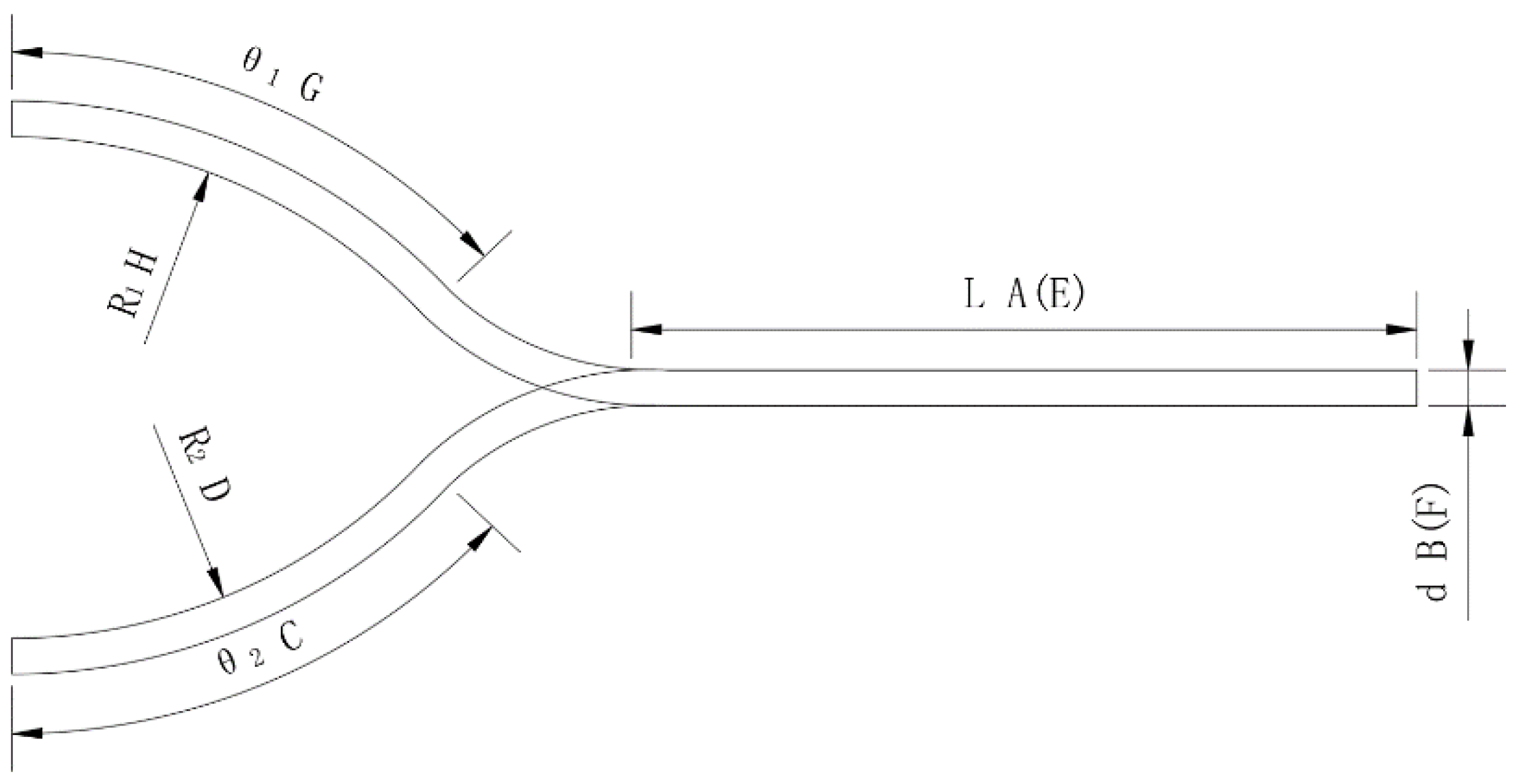
The main dimension parameters of the Y-shaped diversion wall designed in this test are shown in Figure 7, where L is the length of the long straight segment, d is the width of diversion wall, θ1 is the radian of arc segment I, R1 is the arc radius of arc segment I, θ2 is the radian of arc segment II and R2 is the arc radius of arc segment II. According to the operating conditions of the combined sluice-pumping station, arc segment I will sink automatically under the condition of pumping, in which case the length of the long straight segment, the width of the diversion wall, the radian of segment II and the arc radius of arc segment II are regarded as tested factors. Under the condition of self-draining, arc segment I will sink automatically. At this time, the length of the long straight segment, the width of the diversion wall, the radian of segment I and the arc radius of arc segment I are used as tested factors. The height of the diversion wall exceeds the highest water level in both working conditions and it is not used as a variable factor in this test.

Figure 7.
Schematic diagram of the geometric parameters of the guide wall.
For the combined sluice-pumping station with different transverse side angles, the length of the long straight segment of the diversion wall shall be selected according to the range of its bad flow pattern in forebay and ahead of the sluice under the original scheme, which is not designed with any rectification measure. The maximum horizontal width of the diversion wall is 1.2 m, because the distance between the 7# sluice and the 6# pump station inlet tank is 1.2 m. The range of the parameter of radian and the arc radius of arc segment I and II are selected through repeated tests.
3.2. Orthogonal Table
The orthogonal test parameters of the combined sluice-pumping station under the condition of pumping are the length of the long straight segment, the width of the diversion wall, the radian of arc segment II and the arc radius of arc segment II. The orthogonal design of geometric parameters of the Y-shaped diversion wall selects the above four factors, and each factor selects five levels. The specific parameters of factors and levels are shown in Table 1. In the table, A represents the length of the long straight segment, B represents the width of the diversion wall, C represents the radian of arc segment II and D represents the arc radius of arc segment II. Under the condition of self-draining, the orthogonal test parameters are the length of the long straight section, the width of the diversion wall, the radian of arc segment I and the arc radius of arc segment I. The specific parameters of factor level are shown in Table 2. In the table, E represents the length of the long straight segment, F represents the width of the diversion wall, G represents the radian of the arc section I and H represents arc radius of arc segment I.

Table 1.
Orthogonal design of diversion wall (condition of pumping).
Table 2.
Orthogonal design of diversion wall (condition of self-draining).
According to the number of the factors and levels selected, the orthogonal table L25 (54) is designed for orthogonal design under the operating condition of pumping and self-draining, one of which is the error column.
3.3. Orthogonal Test Results of the Geometric Parameters of the Diversion Wall
The preliminary test research shows that under the condition of pumping, the 5# and 6# inlet channels of the combined sluice-pumping station with a 15° lateral side angle, as shown in Figure 8, are mainly affected by the adverse flow pattern in the forebay, endangering the inlet conditions of both inlet channels and thus threatening the stable operation of the pump unit. Under the condition of self-draining, as shown in Figure 9, the flow pattern ahead of the 7# sluice is the most disordered, which reduces the overflow capacity of the sluice. Therefore, under the condition of pumping, the uniformity of axial flow velocity of the inlet section of the 5# and 6# inlet channel is selected as the analysis index. Under the condition of self-draining, the uniformity of the axial flow velocity of the inlet section ahead of the 7# sluice is selected as the analysis index, and the variance analysis of the results of the orthogonal test is carried out. Then, by analyzing the influencing trend of various factors on improving the flow pattern ahead of the sluice and the inlet channel, the combination of the geometric parameters of the diversion wall under two conditions can be obtained.
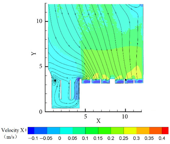
Figure 8.
Diagram of flow field of lower horizontal section (condition of pumping).
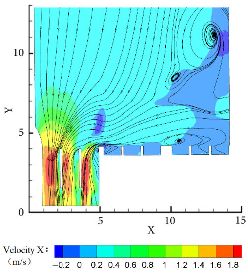
Figure 9.
Diagram of flow field of top horizontal section (condition of self-draining).
In this study, the mean value, range [27] and the main effect diagram were used to analyze the impact sensitivity of different factors tested on indicators. The test results under the two operating conditions are shown in Table 3 and Table 4, where R is the range, which refers to the difference between the maximum and minimum values of the sum of indexes of each layer of the same factor, i.e., Rmax = k1, k2, k3, k4.
Table 3.
Test plan and calculation results (condition of pumping).
Table 4.
Test plan and calculation results (condition of self-draining).
The greater the range, the greater the impact on the index when changing the level of factors; the smaller the range, the smaller the impact.
According to the results of the test, under the condition of pumping, the extreme differences of influence of the length of the long straight segment, the width and the radian of arc segment II and the arc radius of arc segment II exerting on the uniformity of the axial flow velocity of the inlet section of the 5# inlet channel of the combined sluice-pumping station with a 15° lateral angle are 4.08, 3.51, 10.65 and 3.24, respectively. This means that the radian of arc segment II has the greatest influence on the uniformity of the axial flow velocity of the inlet section of the 5# inlet channel, the length of the straight section of the diversion wall and the width of the diversion wall take second and third place, respectively, and the arc radius of arc segment II has minimal influence on the uniformity of the axial flow velocity of the inlet section of the 5# inlet channel. Similarly, the range of the above four factors on the uniformity of axial flow velocity of the inlet section of the 6# inlet channel is 3.39, 5.06, 11.45 and 3.53, respectively, that is, the radian of arc segment II has the greatest impact on the uniformity of the axial flow velocity of the 6# inlet channel, the width and the radius of arc section II take the second place, and the length of the diversion wall has minimal impact on the uniformity of the axial flow velocity of the 6# inlet channel. Under the condition of self-draining, the extreme difference of influence of the length of the long straight section, the width of the diversion wall, the radian of arc segment I and the arc radius of arc section I exerting on the uniformity of the axial flow velocity of the inlet section ahead of the 7# sluice of the combined sluice-pumping station with a 15° lateral angle is 2.15, 3.29, 8.66 and 2.57, respectively. This means that the radian of the circular arc section I has the greatest impact on the uniformity of the axial flow velocity of the inlet section ahead of the 7# sluice, the width of the diversion wall and the arc radius of arc segment I rank second, and the length of the long straight segment has minimal influence on the uniformity of the axial flow velocity of the inlet section ahead of the 7# sluice.
Comprehensive analysis shows that for the combined sluice-pumping station with a 15° lateral angle, under the condition of pumping, among the four factors affecting the rectification effect of the diversion wall, the radian of arc segment II of the diversion wall is the key factor, and the arc radius of arc segment II, the width of the diversion wall and the length of the long straight segment are all general factors. Under the condition of self-draining, the most influential factor on the change of indicators is still the radian of arc segment I of the diversion wall, followed by the width and the arc radius of arc segment I, and the length of the long straight segment is the secondary factor with minimal influence on the change of test index.
Minitab software was used to draw the main effect diagram under two operating conditions, and the specific influence trend of four factors on improving the uniformity of axial flow velocity of the selected inlet section was analyzed. As shown in Figure 10, Figure 11 and Figure 12, the abscissa is the level of each factor, and the ordinate is the average value of the sum of the results of each factor.

Figure 10.
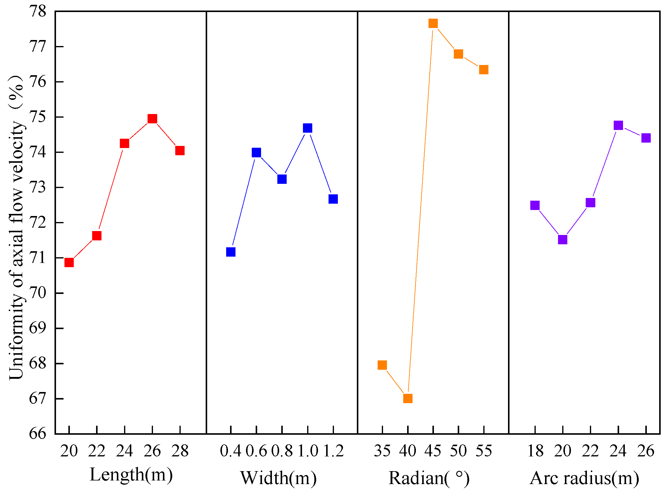
Line graph of the relationship between flow velocity uniformity of the inlet section of 5# channel and various factors.
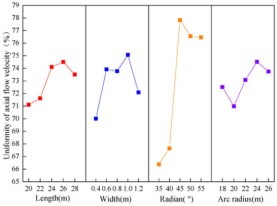
Figure 11.
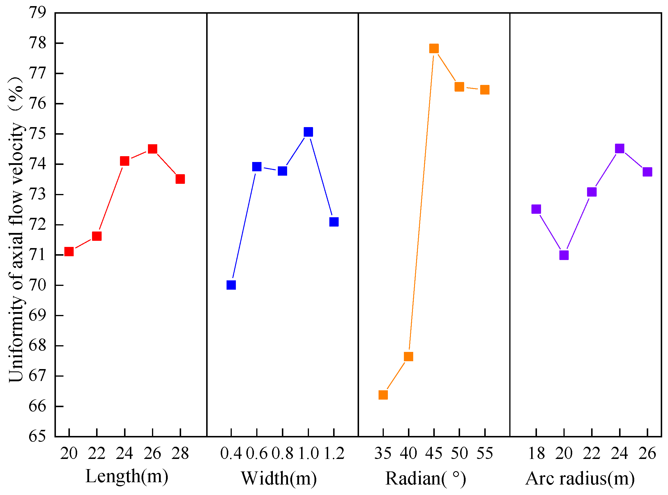
Line graph of the relationship between flow velocity uniformity of the inlet section of 6# channel and various factors.
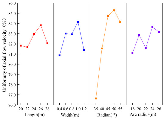
Figure 12.
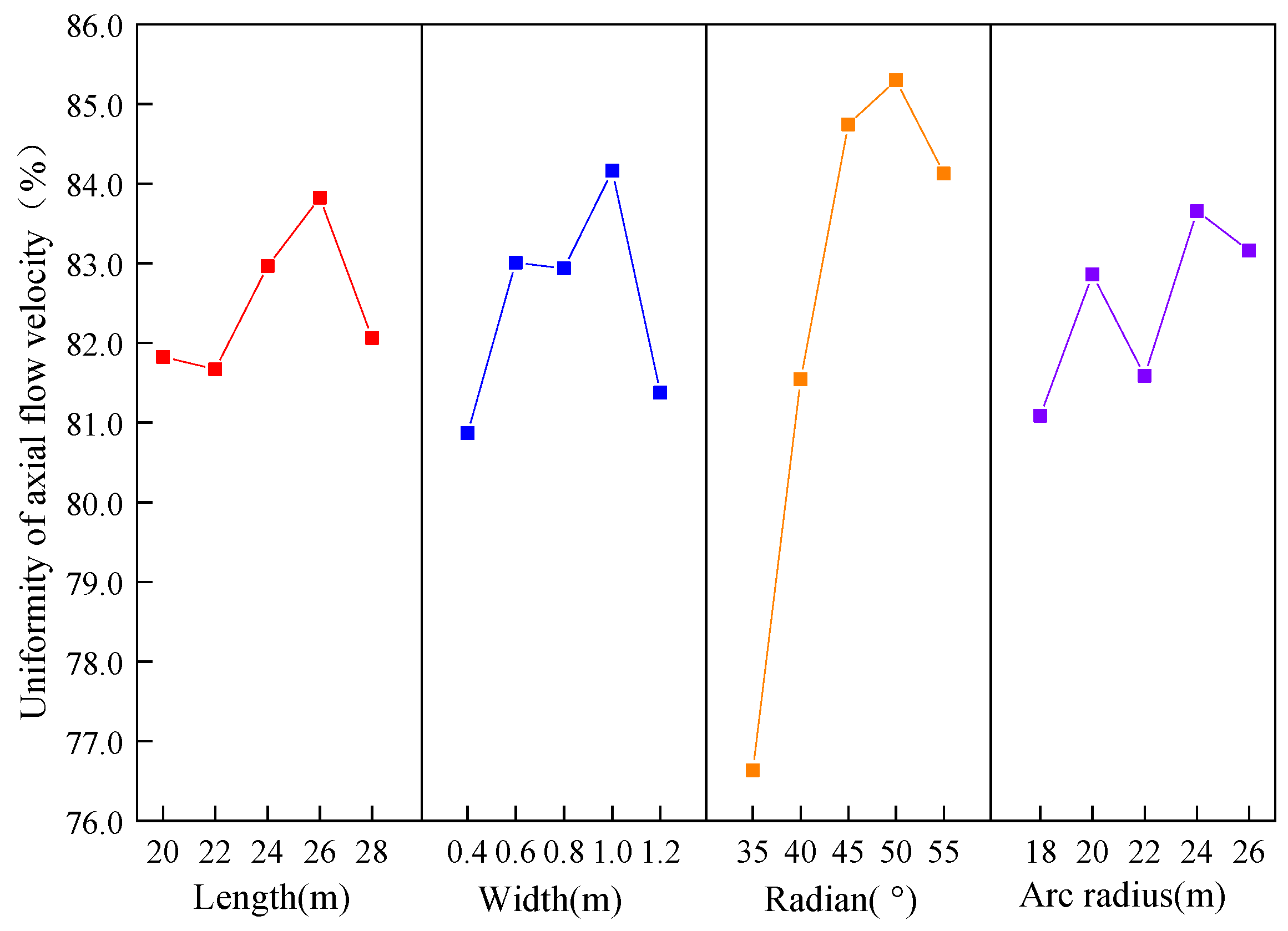
Line graph of the relationship between flow velocity uniformity of inlet section ahead of 7# sluice and various factors.
As shown in Figure 10 and Figure 11, under the condition of pumping, the four research factors have different degrees of impact on the uniformity of axial velocity of the inlet section in the 5# and 6# inlet channels. For the 5# inlet channel, when the length of long the straight segment is 20 m, the value of the test index reaches the minimum. When the length of the long straight segment exceeds 20 m, the value of the test index gradually increases, hitting the peak until the length of the long straight segment reaches 26 m. When the width of the diversion wall changes within the range of factors, the value of the research index is in a fluctuating state. When the width of the diversion wall is 1.0 m, the index value reaches the maximum value. When the radian of arc segment II increases from 35° to 40°, the research index value decreases slightly, while when it increases from 40° to 45°, the research index increases greatly. When the center angle of arc segment II is 45°, the index value reaches the maximum, and a small decrease occurs again after 45°. When the arc radius of arc segment II increases from 18 to 26 m, the value of the research index presents a fluctuating state. During this period, when the arc radius of arc segment II is 24 m, the corresponding index value is the maximum value. For the 6# inlet channel, the effect diagram of the length of the long straight segment, the width of the diversion wall, the radian of the arc section II and the arc radius of the arc section II on the index change is very similar to that of the 5# inlet channel, and its change law and special points have not changed significantly.
As shown in Figure 12, it can be found that the four research factors have different effects on the uniformity of axial flow velocity in front of the 7#sluice under the condition of self-discharge. When the length of the long straight section increases from 20 to 22 m, the research index value decreases slightly. When the length of the long straight section exceeds 22 m, the research index value increases greatly, reaches the peak when the length of the long straight section is 26 m, and continues to decline after 26 m. The effect diagram of the diversion wall width factor is similar to the study effect diagram of the diversion wall width factor on the 5# and 6# inlet channels under pumping and drainage conditions, and the change law and special points have not changed. When the center angle of circular arc section I increases from 35° to 45°, the research index value increases greatly and slows down its growth rate after 45°. When the center angle of circular arc section I is 50°, the index value reaches the maximum. The arc radius factor of arc segment I has a fluctuating change on the research index within the research level, and reaches the maximum at 24 m.
Through comprehensive analysis, two common factors under the two working conditions are compared, namely, the width factor of the diversion wall and the length factor of the long straight segment of the diversion wall. Of the two conditions, the width factor of the diversion wall presents a completely similar influence law on the research indexes, and both of the research indexes reach the maximum when the width of the diversion wall is 1.0 m. The influence laws of the length factors of the long straight segment under two conditions are different, but the special points of the effect diagram still do not change. When the length of the long straight section is 26 m, the value of the research index reaches the maximum.
3.4. Variance Analysis
In order to analyze whether the influence of various factors on the research index is significant and estimate the error during the test, an analysis of the variance of the results of trial is required. The variance calculations are shown in Table 5, Table 6 and Table 7. By calculating whether the variance of each trial factor is less than the variance of the error term, one can judge whether the trial factor will affect the research index of the group. Then, by studying the significance index p under the effect of each factor [27], the significance degree of the factor studied on the research indexes can be obtained.
Table 5.
Analysis of variance of axial flow rate uniformity of 5# inlet channel.
Table 6.
Analysis of variance of axial flow rate uniformity of 6# inlet channel.
Table 7.
Analysis of variance of axial flow rate uniformity in front of 7# sluice.
It can be seen from Table 5 that under the condition of pumping, the changes of the length of the long straight segment of the diversion wall, the width of the diversion wall, the radian of arc segment II and the arc radius of arc segment II will have a certain impact on the change of the uniformity of axial velocity of the inlet section of the 5# inlet channel. Among them, the change of the radian of arc section II has a very significant impact on the research index, while the change of the length of the long straight segment of the diversion wall, the width of the diversion wall and the arc radius of circular arc segment II generally have a significant impact on the research index. It can be seen from Table 6 that under the condition of pumping, the changes of the length of the long straight segment of the diversion wall, the width of the diversion wall, the radian of arc segment II and the radius of arc section II will have a certain impact on the change of the uniformity of the axial velocity of the inlet section of the 6# inlet channel. Among them, the change of the radian of arc segment II has a very significant impact on the research indicators, while the change of the length of the long straight segment of the diversion wall, the width of the diversion wall and the arc radius of arc section II generally have a significant impact on the research indicators.
It can be seen from Table 7 that under the condition of self-draining, the change of the length of the long straight segment of the diversion wall and the arc radius of segment I do not have a significant impact on the change of the axial velocity uniformity of the inlet section in front of the 7# sluice, that is, any parameter within the test range can be selected according to the specific situation, and the change of the width of the diversion wall and the radian of arc segment I can have a significant impact on the research indicators. Of the two, the change of radian of arc segment I can have a very significant impact on the index.
3.5. Determination of Optimal Solution
For the combined sluice-pumping station, under the condition of pumping and self-draining, the greater the value of the uniformity of the axial velocity in the inlet channel and in front of the sluice, the better the flow pattern is. According to the results of the above orthogonal test and the influence analysis of relevant factors, the following optimal test scheme can be obtained. Under the condition of pumping, it can be seen from Figure 10 and Figure 11 that among the five levels considered for the length of the long straight segment of the diversion wall, when the length of the long straight section is 26 m, the two test index values are the largest. Among the five levels considered for the width of the diversion wall, when the width of the diversion wall is 1.0 m, the two test index values are the largest. Among the five levels considered for the radian of arc segment II, when the radian of arc segment II is 45°, the two test index values are the largest. Among the five levels considered for the arc radius of arc section II, when the arc radius of arc section II is 24 m, the two test index values are the largest. Therefore, for the combined sluice-pumping station with a 15° lateral angle, the optimal design scheme of the diversion wall under the condition of pumping is as follows: the length of the long straight segment: 26 m, the width of diversion wall: 1.0 m, the radian of arc segment II: 45°, and the arc radius of arc segment II: 24 m. Thus, the optimal scheme is A4B4C3D4.
Under the condition of self-draining, it can be seen from Figure 12 that among the five levels considered for the length of the long straight segment of the diversion wall, the test index value is the largest when the length of the long straight segment is 26 m. Among the five levels considered for the width of the diversion wall, the test index value is the largest when the width of the diversion wall is 1.0 m. Among the five levels considered for the radian of circular arc segment I, the test index value is the largest when the radian of arc segment II is 50°. Among the five levels considered for the arc radius of arc segment I, the test index value is the largest when the arc radius of arc segment I is 24 m. Therefore, for the combined sluice-pumping station with a 15° lateral angle, the optimal design scheme of the diversion wall under the condition of self-draining is as follows: the length of long straight section: 26 m, the width of diversion wall: 1.0 m, the center angle of circular arc section I: 50°, and the arc radius of arc body section I: 24 m. Thus, the optimal scheme is E4F4G4H4.
To sum up, A4B4C3D4E4F4G4H4 is the best experimental scheme for the combined sluice-pumping station with a 15° transverse side angle with the design of the Y-shaped settling diversion wall of the project. However, since both the A4 and E4 are the length factors of the long straight segment of the diversion wall and their levels are consistent and both B4 and F4 are the width factors of the diversion wall and their levels are consistent, the final optimal scheme is A4B4C3D4G4H4.
4. Analysis of Numerical Simulation Results Based on Orthogonal Experimental Design
4.1. Feature Section Selection
Under the condition of pumping, there are two characteristic sections of the horizontal section of the forebay of the pump station selected for flow field analysis, namely, the surface and bottom horizontal sections of the forebay. Figure 13 is the schematic diagram of the horizontal section position under the condition of pumping, i.e., surface section A-A and bottom section B-B. The flow pattern and axial flow velocity distribution of the surface and bottom of the forebay are studied, respectively. The surface layer A-A section is 0.6 m away from the water surface, and the coordinate of the bottom layer B-B section is Z of 7.1 m.
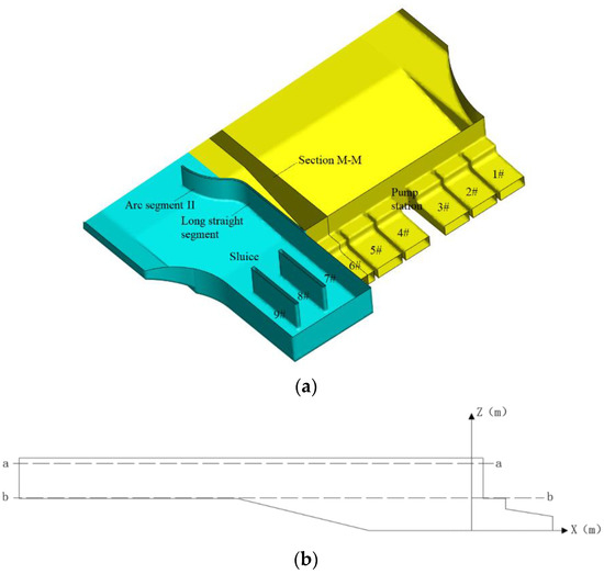
Figure 13.
Schematic position of horizontal profile (condition of pumping): (a) schematic diagram of section position; (b) sectional profile M-M.
Under the condition of self-draining, the horizontal section of the surface layer in front of the sluice is selected and the flow field is analyzed to study the flow pattern and axial and transverse velocity distribution of the surface layer in front of the sluice. Figure 14 is the position diagram of the horizontal section under the condition of self-draining, i.e., section C-C, which is 0.6 m away from the water surface.
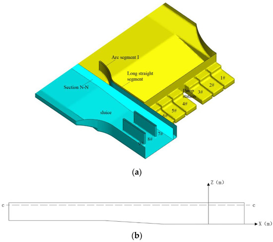
Figure 14.
Schematic position of the horizontal profile (condition of self-draining): (a) schematic diagram of section position; (b) sectional profile N-N.
4.2. Selection of the Typical Schemes
The schemes of 25 combinations of diversion wall parameters under two working conditions are calculated by an orthogonal test, and the optimal combination of diversion wall parameters has been obtained. To further analyze and verify the results of the orthogonal test, the scheme with the relatively high uniformity of axial flow velocity should be selected from these 25 schemes under the condition of pumping and self-draining. Then, to ensure the accuracy of the orthogonal test results, the flow patterns in the forebay and in front of the sluice are studied, and the selected scheme is analyzed and compared with the optimal scheme calculated by the orthogonal test. Under the two operating conditions, four representative schemes with high research indexes and scattered test factors are selected for numerical simulation analysis together with the optimal scheme calculated by the orthogonal test. The selected typical schemes are shown in Table 8 and Table 9, where C1 and Z1, respectively, represent the optimal scheme under the condition of pumping and the optimal scheme under the condition of self-draining obtained by orthogonal test.
Table 8.
Typical calculation scheme of the numerical model (condition of pumping).
Table 9.
Typical calculation scheme of the numerical model (condition of self-draining).
4.3. Analysis of the Numerical Simulation Results
4.3.1. Condition of Pumping
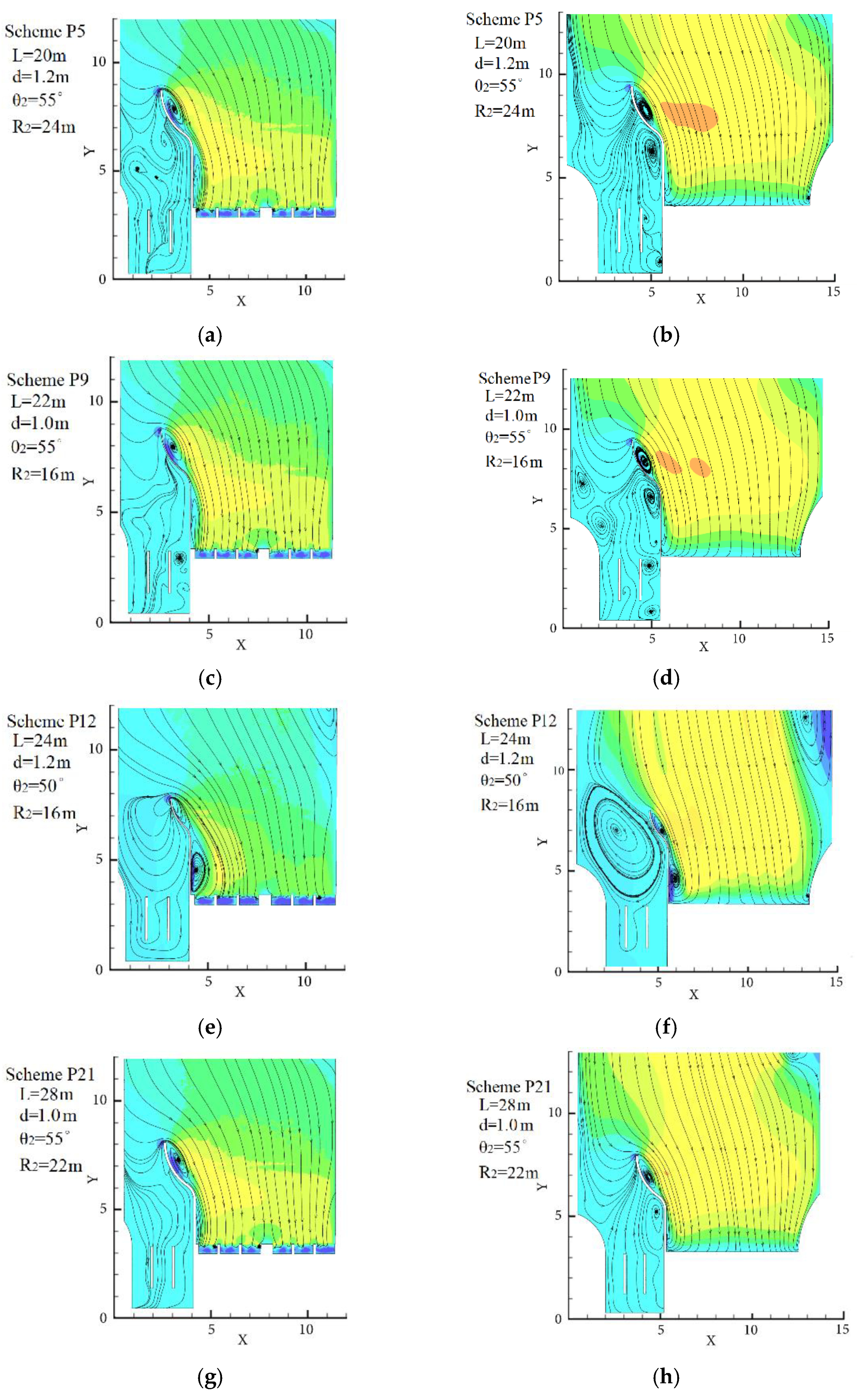
Numerical simulation of the five schemes was performed under the condition of pumping, and by observing the following flow field diagrams we can intuitively understand the specific inflow flow patterns. If there are some bad flow patterns occurring in the forebay, we can also quickly locate the occurrence location as well as its distribution area, and then, according to its distribution characteristics, we can have the schemes analyze and verify the rationality of the results of the orthogonal test.
The surface and underlying horizontal cross section of the flow field is shown in Figure 15. It can be seen that under all schemes, there is a low-speed area in the left side wall of the diversion wall, where a small-scale reflux area appears inside circular arc section II, and the position of the reflux area from the bottom layer to the surface layer does not change. The backflow center is always at X of 3.5 and Y of 7.8, which is far from the forebay of the pump station, so it will not have a direct adverse impact on the inlet conditions of the pump station.

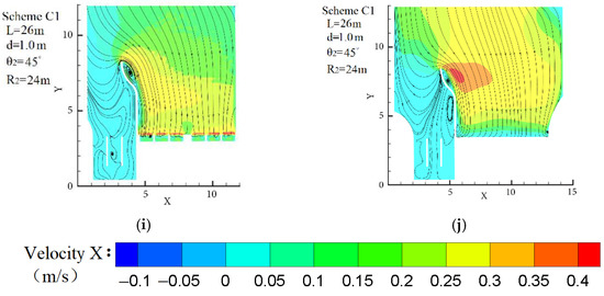
Figure 15.
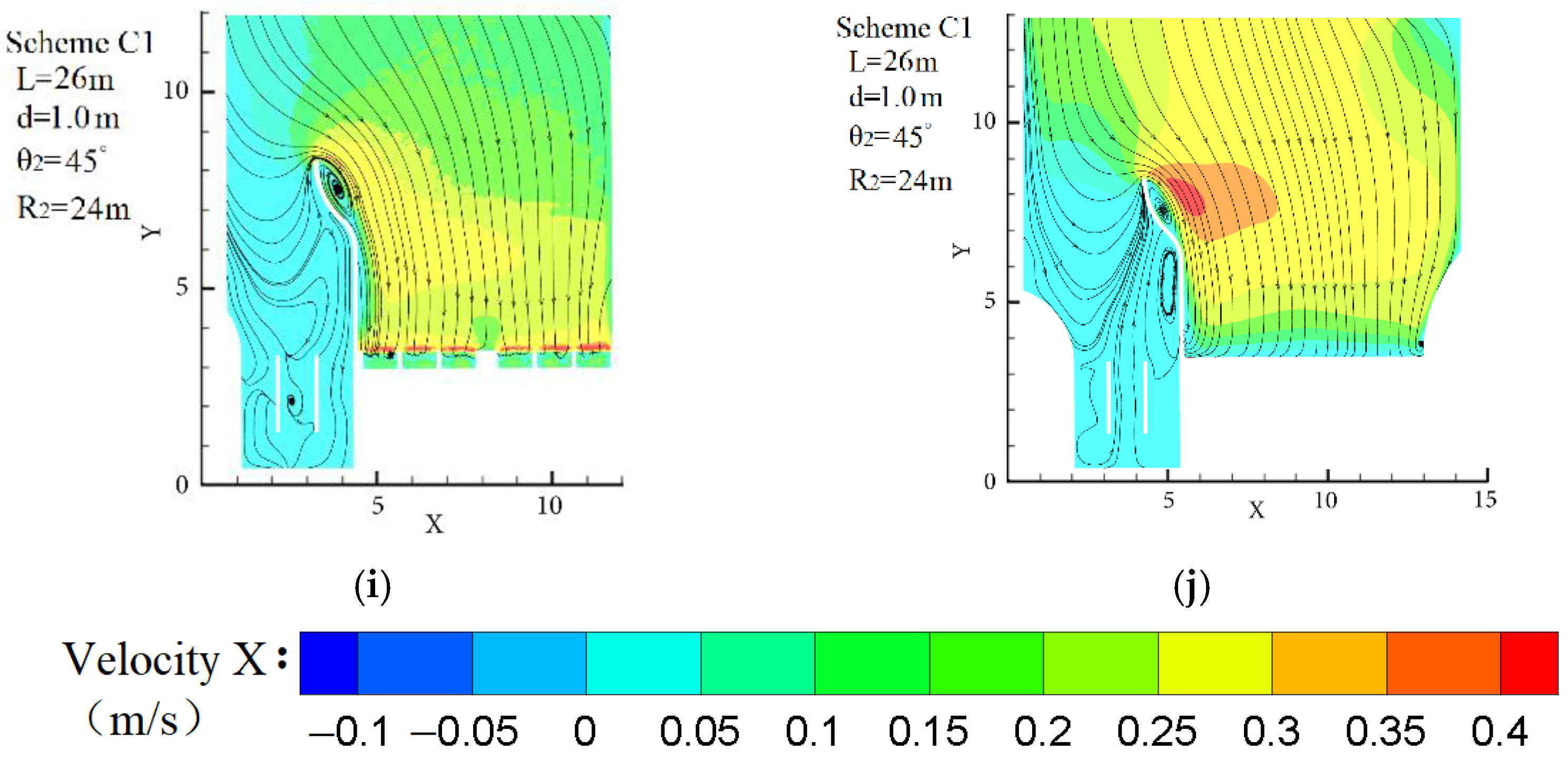
Surface and bottom horizontal cross-sectional flow field diagrams of different schemes: (a) P4 bottom flow field distribution; (b) P4 surface flow field distribution; (c) P9 bottom flow field distribution; (d) P9 surface flow field distribution; (e) P12 bottom flow field distribution; (f) P12 surface flow field distribution; (g) P21 bottom flow field distribution; (h) P21 surface flow field distribution; (i) C1 bottom flow field distribution; (j) C1 surface flow field distribution. Note: All charts in Figure 15 share a common legend.
In Figure 15a,b, due to the small length of the long straight segment of the diversion wall in this scheme, there is a reflux area on the left side of the long straight section of the 6# diversion wall, which affects the inflow of the 6 # inlet channel.
In Figure 15c,d, there is also a reflux area on the left side of the long straight section of the diversion wall. Compared with scheme P5, the length of the long straight segment in scheme P9 is higher, resulting in a reduction in the area of the reflux area on the left side of the long straight segment of the diversion wall.
In Figure 15e,f, there is an obvious reflux area on the left side of the long straight segment, and the reflux center of the bottom layer is at X of 4.3 and Y of 4.2. From the bottom layer to the surface layer, the area of the reflux area shrinks gradually. Compared with scheme P5 and scheme P9, scheme P12 mainly changes the radian of arc segment II from 55° to 50°, which directly reduces the transverse length of the diversion wall, leading to some backflow at the sluice side bypassing the diversion wall into the forebay of the pump station, thus increasing the oblique flow at the head of the diversion wall. The left side of the long straight segment of the diversion wall has a large area of reflux, which affects the inlet flow pattern of the 5# and 6# inlet channels.
In Figure 15g,h, there is also a small-scale reflux area on the left side of the long straight segment of the diversion wall. Comparing scheme P21 with scheme P5 and scheme P9, the length of the long straight segment in scheme P21 is higher than that in scheme P5 and scheme P9, so the backflow on the left side of the long straight segment of the diversion wall is greatly improved.
In Figure 15i,j, the flow velocity of the surface layer of the forebay in scheme C1 is slightly greater than that of the bottom layer, and the flow velocity of the surface layer of the forebay tends to decrease from the middle to both sides. When the water flows from the forebay to the front of the inlet channel, the flow velocity of the surface layer gradually decreases. In scheme C1, the flow field at the bottom of the forebay is similar to that of the surface and the streamline is smooth, so the 1#–6# inlet channels have relatively good inlet conditions. The diversion wall under this scheme can effectively improve the inflow flow pattern of the forebay.
To conclude, as shown in Figure 15, Figure 15i,j shows the smoothest streamline of the surface layer and the bottom layer, and the flow field related is the best, that is, scheme C1 is the optimal scheme and its diversion wall parameter combination is A4B4C3D4. The uniformity levels of the 5# and 6# inlet channel axial velocities are 80.35% and 80.71%, respectively, which are higher than those of four other schemes. It shows that the result of orthogonal experimental design is basically consistent with that of numerical simulation analysis.
4.3.2. Condition of Self-Draining
Numerical simulation is carried out for the five schemes under the condition of self-draining. The surface flow pattern and axial and transverse velocity distribution in front of the sluice are shown in Figure 16. It can be found that there is a small range of reflux area in arc segment I on the right side of the diversion wall under all schemes, and its reflux center is located at X of 6 and Y of 7.5. However, since the reflux zone is far from the sluice, it will not have a direct adverse impact on the inlet conditions of the sluice. On the right side of the long straight segment of the diversion wall, there is no reflux area, and the streamline is relatively smooth.
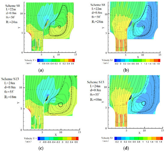
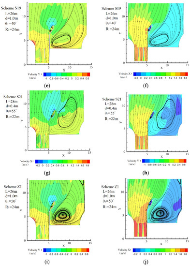
Figure 16.
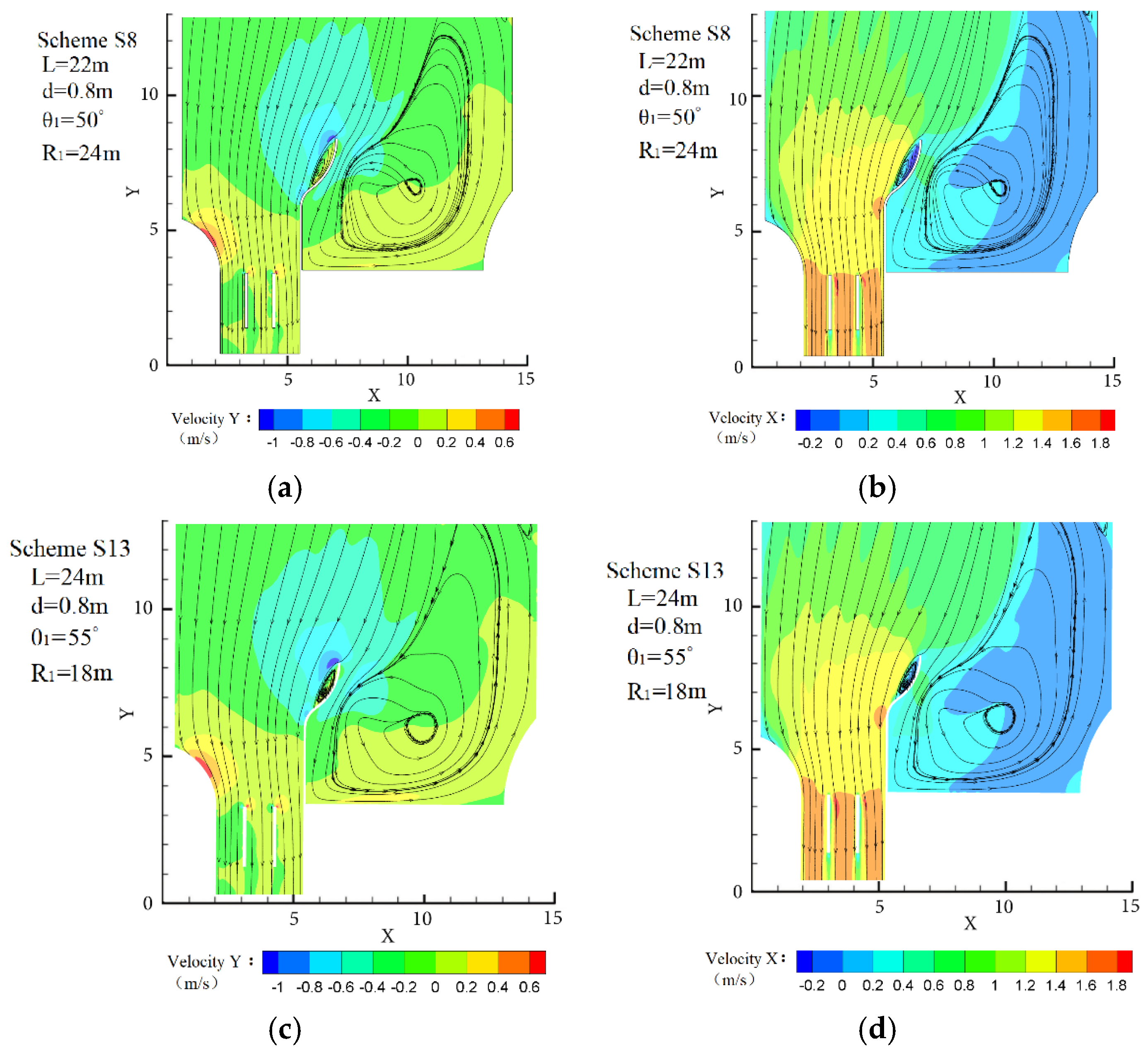
Surface flow pattern and axial and lateral velocity distribution of different schemes: (a) S8 lateral velocity cloud diagram; (b) S8 longitudinal velocity cloud diagram; (c) S13 lateral velocity cloud diagram; (d) S13 longitudinal velocity cloud diagram; (e) S19 lateral velocity cloud diagram; (f) S19 longitudinal velocity cloud diagram; (g) S21 lateral velocity cloud diagram; (h) S21 longitudinal velocity cloud diagram; (i) Z1 Lateral velocity cloud map; (j) Z1 longitudinal velocity cloud map.
The maximum transverse flow velocity at the head of the diversion wall is 0.5 m/s and the maximum axial flow velocity is 1.4 m/s under the schemes of S8, S13, S19 and S21, so there is a certain oblique flow phenomenon existing at the head of the diversion wall. Contrastingly, as for the scheme Z1, its maximum transverse velocity at the head of the diversion wall is 0.28 m/s, which is 0.22 m/s lower than that of the other four schemes, and the maximum axial velocity is 1.15 m/s, which is 0.25 m/s lower than that of the other four schemes. Therefore, the oblique flow phenomenon in front of the wall head has been improved.
To, conclude, in Figure 16i,j, the transverse and axial velocity in front of the diversion wall is the smallest, the streamline in front of the sluice is smooth, and the flow field is the best, that is, the optimal combination of parameters of the diversion wall is E4F4G4H4 and the uniformity of axial velocity in front of the 7# sluice is 86.65%, which is higher than the test indexes of the other four excellent schemes directly observed in the orthogonal test. So, the results of orthogonal experimental design are basically consistent with those of numerical simulation analysis.
5. Discussion
Xu et al. [28] designed a scheme of perforated diversion pier by combining a physical model test and numerical simulation and studied the flow state in the forebay of a sluice-pumping station. The model test results are consistent with and mutually verified by the numerical simulation results. They all show that when the length of the perforated diversion wall is 8.62D (D is the diameter of the pump impeller), the width of the opening is 1.55D, the center spacing of adjacent orifices is 2.16D, the opening height is 0.66 h (h is the water depth of the forebay), the flow pattern of the forebay is the best, and the inlet velocity distribution of the inlet channel is the most uniform. Meanwhile, the large-scale high-speed transverse velocity zone at the head of the diversion wall is also greatly weakened.
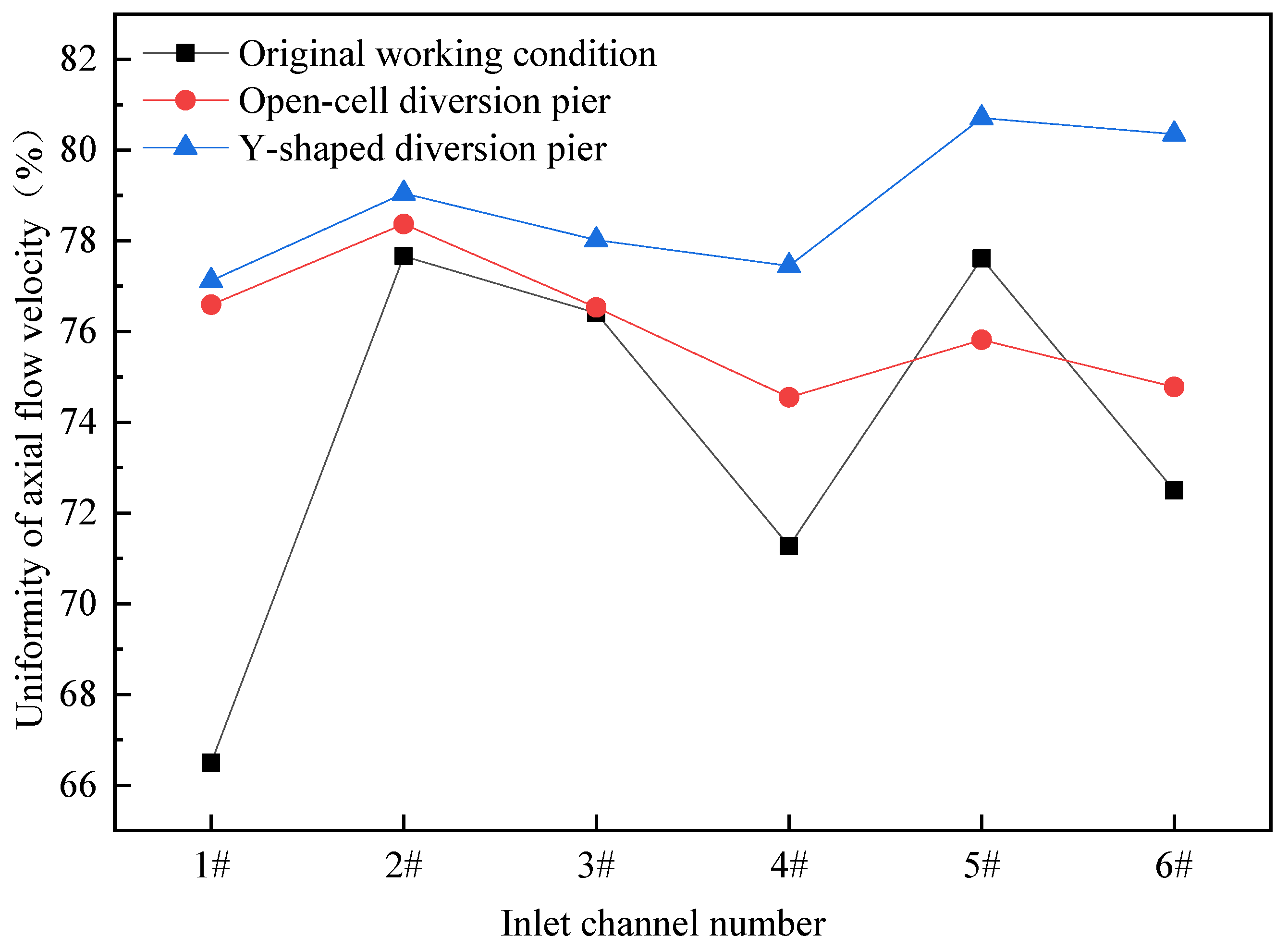
In this study, the inlet flow pattern of the Y-shaped settlement diversion wall under two operating conditions is numerically simulated, and the error between the model grid number and the model grid number in [28] is controlled within 3% for horizontal comparison of data. The results are shown in Figure 17 and it can be seen that the axial velocity uniformity of inlet sections of the 1#–6# inlet channels under the condition of pumping are 77.12%, 79.05, 78.02%, 77.45%, 80.71% and 80.35%, respectively. It can be found that after adding the Y-shaped settling diversion wall, the research indexes are increased by 10.62%, 1.39%, 1.61%, 6.18%, 3.1% and 7.85%, respectively, indicating that the Y-shaped settling diversion wall can improve the flow pattern of all channels. Compared with the perforated diversion wall scheme in [28], the Y-shaped settlement diversion wall scheme increases the research indexes by 0.69%, 0.87%, 1.95%, 3.89%, 6.45% and 7.45%, respectively. The results show that compared with the perforated diversion wall, the Y-shaped diversion wall plays a relatively more significant role in improving the velocity uniformity of the 5# channel and 6# channel, mainly because the raceway in front of the 5# and 6# channel has basically disappeared, which is consistent with the results of numerical simulation.
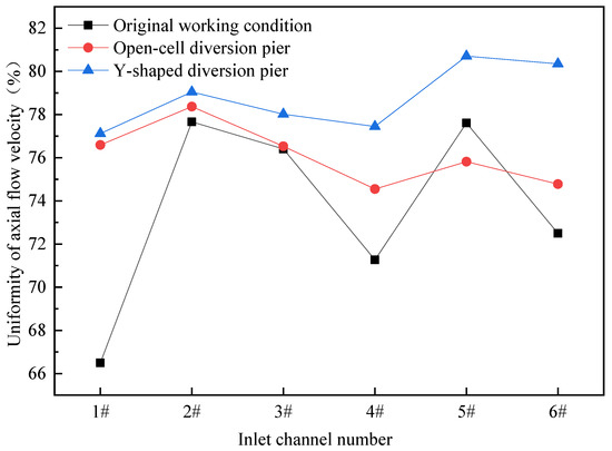
Figure 17.
Comparison of diversion pier scheme (condition of pumping).
Xu et al. [12] carried out numerical simulation on the navigable flow conditions of the combined sluice-pumping station, and analyzed the effects of length of the diversion pier, opening width, center spacing of adjacent orifices and opening height on the navigable flow conditions of the combined sluice-pumping station. The results show that the perforated diversion pier can reduce the transverse and axial velocity of the water flow surface layer in front of the pier head. Under the optimal scheme of the diversion pier, the transverse velocity and axial velocity of the water flow in front of the pier head are 0.25 and 0.75 m/s, respectively. In the study of this article, under the condition of self-draining, the maximum transverse velocity and maximum axial velocity in front of the wall head of the diversion wall are 0.28 and 1.15 m/s, respectively. Compared with the scheme without the diversion pier, the maximum transverse velocity is reduced by 0.52 m/s, and the maximum axial velocity is reduced by 0.65 m/s. This result shows that the Y-shaped settling diversion wall can effectively improve the flow pattern in front of the sluice of the combined sluice-pumping station and the maximum transverse velocity is less than the regulated value of 0.3 in [29], which has met the requirement of navigation. However, compared with the perforated diversion pier scheme in [12], the maximum transverse velocity and maximum axial velocity in front of the diversion pier head are 0.03 and 0.4 m/s higher, respectively. It shows that under the condition of self-draining, the perforated diversion wall scheme has a slightly significant effect on alleviating the oblique flow problem on the inlet side of the sluice of the combined sluice-pumping station. Therefore, the perforated rectification research on the Y-shaped settling diversion wall can be considered in the future to achieve the optimal effect under multiple working conditions.
6. Conclusions
The rectification measures of the combined sluice-pumping station with a transverse lateral angle of 15° are studied. Some geometric parameters of the diversion wall are designed by the method of orthogonal testing, and the optimized parameter combination is obtained through the analysis of the orthogonal test results. Then, CFD numerical simulation is used to verify the analysis results. The results show that:
- Adding a Y-shaped settling diversion wall between the sluice and the pump station can effectively improve the inlet flow pattern of the combined sluice-pumping station, and the orthogonal test is of great scientific value to analyze such a fluid mechanical engineering issue to obtain the influence degree of various factors on the index.
- The geometric parameters of different diversion walls have different effects on the uniformity of axial velocity in front of the sluice and in the inlet section of the inlet channel. Under the condition of pumping, among the four factors affecting the rectification effect of the diversion wall, the radian of arc segment II of the diversion wall is the key factor, and the arc radius of arc segment II, the width of the diversion wall and the length of the long straight section are all general factors. Under the condition of self-draining, the most influential factor on the index change is still the radian of arc segment I of the diversion wall, followed by the width of the diversion wall and the arc radius of arc segment I, and the length of the long straight segment is the secondary factor with the least influence on the index change.
- For the combined sluice-pumping station with a 15° lateral angle, the parameter combination A4B4C3D4G4H4 of the Y-shaped settling diversion wall is adopted as the optimal experimental scheme, that is, under the condition of pumping, when the length of the long straight segment is 26 m, the width of the diversion wall is 1.0 m, the radian of arc segment II is 45° and the arc radius of arc section II is 24 m, the two test index values are the maximum. Under the condition of self-draining, when the length of the long straight segment is 26 m, the width of the diversion wall is 1.0 m, the radian of the arc section II is 50°, and the arc radius of the arc section I is 24 m, the test index value is the maximum.
- The Y-shaped settling diversion wall studied in this paper optimizes the inlet conditions of the side wall by isolating the backflow, which can achieve the optimal inlet flow pattern under the conditions of pumping and self-drainage. So, it can be well applied in the combined sluice-pumping station with a 15° transverse lateral angle. The results of this research provide a scientific basis and technical reference for the design of the combined sluice-pumping station with a diversion pier under other lateral corners or other operating conditions.
Author Contributions
Conceptualization, B.X. and J.L.; methodology, B.X.; software, B.X.; validation, W.L., B.X. and J.L.; formal analysis, J.L.; investigation, B.X.; resources, B.X.; data curation, J.L.; writing—original draft preparation, J.L.; writing—review and editing, J.L.; visualization, J.L.; supervision, B.X.; project administration, W.L.; funding acquisition, W.L. All authors have read and agreed to the published version of the manuscript.
Funding
This research was funded by the National Natural Science Foundation of China (No. 52079120; Funder: Bo Xu), the National Natural Science Foundation of China (51779215, Funder: Weigang Lu).
Institutional Review Board Statement
Not applicable.
Informed Consent Statement
Not applicable.
Data Availability Statement
Not applicable.
Conflicts of Interest
The authors declare no conflict of interest.
References
- Chen, Y.; Yang, J.; Yu, J.; Fu, Z.; Chen, Q. Flow Expansion and Deflection Downstream of a Symmetric Multi-gate Sluice Structure. KSCE J. Civ. Eng. 2020, 24, 471–482. [Google Scholar] [CrossRef]
- Mohamed, I.M.; Abdelhaleem, F.S. Flow Downstream Sluice Gate with Orifice. KSCE J. Civ. Eng. 2020, 24, 3692–3702. [Google Scholar] [CrossRef]
- Song, W.; Pang, Y.; Shi, X.; Xu, Q. Study on the rectification of forebay in pumping station. Math. Probl. Eng. 2018, 1, 1–16. [Google Scholar] [CrossRef]
- Xi, W.; Lu, W.; Wang, C.; Xu, B. Optimization of the Hollow Rectification Sill in the Forebay of the Pump Station Based on the PSO-GP Collaborative Algorithm. Shock. Vib. 2021, 1, 1–11. [Google Scholar] [CrossRef]
- Fan, J.; Lu, D.; Shi, Z.; Hou, H. Lateral Water Pumping Station Forebay of Jingtai Electric Power Irrigation District Flow State Numerical Simulation and Preventing Silt Research. Int. J. Comput. Eng. 2016, 1, 30–32. [Google Scholar]
- Teaima, I.R.; El-Gamal, T. Improving flow performance of irrigation pump station intake. J. Appl. Water Eng. Res. 2017, 5, 9–21. [Google Scholar] [CrossRef]
- Zhao, Z.; Qian, Z.; Guo, Z.; Wu, P. Experimental study of subsurface vortices in pump intake with an improved diversion-cone. In Proceedings of the IOP International Conference Series of Earth and Environmental Science, Shanghai, China, 25–26 March 2019; p. 32. [Google Scholar]
- Zhang, L.; Wang, C.; Zhang, Y.; Xiang, W.; He, Z.; Shi, W. Numerical study of coupled flow in blocking pulsed jet impinging on a rotating wall. J. Braz. Soc. Mech. Sci. Eng. 2021, 43, 508. [Google Scholar] [CrossRef]
- Tang, S.; Yuan, S.; Zhu, Y. Deep learning-based intelligent fault diagnosis methods toward rotating machinery. IEEE Access 2019, 8, 9335–9346. [Google Scholar] [CrossRef]
- Tang, S.; Yuan, S.; Zhu, Y. Data preprocessing techniques in convolutional neural network based on fault diagnosis towards rotating machinery. IEEE Access 2020, 8, 149487–149496. [Google Scholar] [CrossRef]
- Wang, H.; Qian, Z.; Zhang, D.; Wang, T.; Wang, C. Numerical study of the normal impinging water jet at different impinging height, based on Wray–Agarwal turbulence model. Energies 2020, 13, 1744. [Google Scholar] [CrossRef] [Green Version]
- Xu, B.; Zhang, C.; Li, Z.; Gao, C.; Bi, C. Study on the influence of geometric parameters of diversion pier on navigable flow conditions of gate station joint hub based on CFD. J. Irrig. Drain. 2019, 38, 115–122. (In Chinese) [Google Scholar]
- Zhao, M.; Jia, J.; Qin, J.; Liang, J.; Yang, F. Simulation of diversion pier rectification of gate station combined with pump station forebay. China Rural. Water Resour. Hydropower 2018, 4, 125–130. (In Chinese) [Google Scholar]
- Zhang, C.; Zhou, C.; Zhou, Y.; Xu, L. Influence of geometric parameters of ‘Y’ diversion pier on flow pattern in forebay of lateral intake pump station. S. N. Water Transf. Water Conserv. Sci. Technol. 2020, 18, 192–200. (In Chinese) [Google Scholar]
- Cheng, L.; Qi, W.; Luo, C.; Shang, Y.; Yuan, H. Effect of geometric parameters of Y-shaped diversion piers on flow pattern in forebay of pumping station. Adv. Sci. Technol. Water Resour. 2014, 34, 68–72. [Google Scholar]
- Xi, B.; Zhen, Y.; Duan, Y.; Yang, X.; Lu, R. Optimization of flow pattern in forebay of gate station combined pump station. J. Chang. Acad. Sci. 2021, 1, 9–28. (In Chinese) [Google Scholar]
- Zhou, J.; Zhao, M.; Wang, C.; Gao, Z. Optimal design of diversion piers of lateral intake pumping station based on orthogonal test. Shock. Vib. 2021, 5, 1–9. [Google Scholar] [CrossRef]
- Zhou, L.; Shi, W.; Lu, W.; Xu, R.; Wang, C. Orthogonal test and optimization design of submersible pump guide vanes. J. Drain. Irrig. Mach. Eng. 2011, 29, 312–315. [Google Scholar]
- Shi, G.; Li, H.; Liu, X.; Liu, Z.; Wang, B. Transport Performance Improvement of a Multiphase Pump for Gas–Liquid Mixture Based on the Orthogonal Test Method. Processes 2021, 9, 1402. [Google Scholar] [CrossRef]
- Yang, Y.; Zhou, L.; Zhou, H.; Lv, W.; Wang, J.; Shi, W.; He, Z. Optimal Design of Slit Impeller for Low Specific Speed Centrifugal Pump Based on Orthogonal Test. J. Mar. Sci. Eng. 2021, 9, 121. [Google Scholar] [CrossRef]
- Bouhmala, N.; Cai, X. Partition of unstructured finite element meshes by a multilevel approach. In Proceedings of the International Workshop on Applied Parallel Computing in Springer, Heidelberg/Berlin, Germany, 20–23 June 2000; pp. 187–195. [Google Scholar]
- Lee, M.H.; Kim, C.M.; Park, G.Y.; Choi, C.H.; Park, C.Y. Grid Independence Test of Computational Fluid Dynamics Model for Indoor Airflow Analysis. J. Korean Inst. Archit. Sustain. Environ. Build. Syst. 2020, 10, 183–194. [Google Scholar]
- Xu, L.; Lu, W.; Lu, L.; Dong, L.; Wang, Z. Flow patterns and boundary conditions for inlet and outlet conduits of large pump system with low head. Appl. Math. Mech. 2014, 35, 675–688. [Google Scholar] [CrossRef]
- Ismail, M.; Fartaj, A.; Karimi, M. Numerical investigation on heat transfer and fluid flow behaviors of viscous fluids in a minichannel heat exchanger. Numer. Heat Transf. Part A Appl. 2013, 64, 1–29. [Google Scholar] [CrossRef]
- Axell, L.B.; Liungman, O. A one-equation turbulence model for geophysical applications: Comparison with data and the k—ε model. Environ. Fluid Mech. 2001, 1, 71–106. [Google Scholar] [CrossRef]
- Mousavi, S.F.; Hosseini, K.; Fouladfar, H.; Mohammadian, M. Comparison of different turbulence models in predicting cohesive fluid mud gravity current propagation. Int. J. Sediment Res. 2020, 35, 504–515. [Google Scholar]
- Ying, Z.; Seberry, J.; Xia, T.; Wysocki, B.J.; Wysocki, T.A. Construction of amicable orthogonal designs of quaternions. Australas. J. Comb. 2009, 44, 19–35. [Google Scholar]
- Xu, B.; Gao, C.; Xia, H.; Lu, W. Influence of geometric parameters of perforated diversion pier on rectification effect of forebay of gate station project. J. Chang. Acad. Sci. 2019, 36, 58–62. (In Chinese) [Google Scholar]
- China Communications Planning and Design Institute for Water Transportation. Code for Master Design of Shiplocks, 1st ed.; Nanhai Press: Haikou, China, 2002; pp. 305–2001. [Google Scholar]


Publisher’s Note: MDPI stays neutral with regard to jurisdictional claims in published maps and institutional affiliations. |
© 2022 by the authors. Licensee MDPI, Basel, Switzerland. This article is an open access article distributed under the terms and conditions of the Creative Commons Attribution (CC BY) license (https://creativecommons.org/licenses/by/4.0/).