Abstract
Model-based force control for motion and force tracking faces significant challenges on real quadruped platforms due to the apparent model inaccuracies. In this paper, we present a multi-objective optimal torque control for hydraulic quadruped robots under significant model errors, such as non-modelable hydraulic components, linearization, disturbances, etc. More specifically, the centroidal dynamics are first modeled to project the dynamics of the floating-based whole-body behaviors to the centroidal frame. Model error compensation mechanisms are subsequently developed to track the reference motion of the CoM, torso, and foot-end trajectories, which are mapped into the joint space. Furthermore, a multi-objective optimal torque control scheme is formulated using quadratic programming (QP) to coordinate follow the reference motion and ground reaction forces simultaneously while satisfying all constraints. Finally, we present a series of simulations as well as experiments on a real hydraulic quadruped platform, EHbot. The results demonstrate that the proposed torque control scheme is robust to large model inaccuracies and improves the performance of the overall system.
1. Introduction
As an important branch of the field robots, legged robots, especially hydraulic quadruped robots, have superior abilities over wheeled and tracked counterparts regarding to their dynamic balance, load capacity, and unstructured terrain adaptation [1,2,3]. Those distinct characteristics take their first steps outside the laboratories and into the real world. Accordingly, legged robots possess profound potential in applications in unknown and high-risk prospects such as hazardous environment reconnaissance, fire rescuing, military missions, and nuclear radiation scenarios [4,5]. The specific challenges for these scenario applications are the demands for rapid response to external disturbances and adaptation to unknown environmental changes. Due to the high dimensional degrees of freedom (DoFs), position controllers make complex behaviors kinematically feasible. However, they are inevitably restricted to quasi-static regions [6].
In recent years, researchers have explored control systems shifting away from position control paradigms to force control to deal with these challenges [7]. Generally speaking, the solution of force control, especially model-based torque control, can be further divided into joint space and operational space controllers. The former is a classical approach, widely applied to fixed-based manipulators. In the field of legged robots, it is extended and used to track the joint trajectories via inverse kinematics by feed-forward torque command calculating [8]. Thereby, the legged robots can achieve the desired motion [9]. The latter provides an elegant solution to generate whole-body behaviors in intuitive motion spaces, which is more suitable for legged locomotion [10]. One of the most well-known methods is the one proposed by Khatib [11,12]. Specifically, by defining the task priorities in a hierarchical manner, operational space control enables various dynamic behaviors while maintaining fundamental constraints, such as contacts, joint limits, and dynamic balance, simultaneously. The hierarchically prioritized operational space control allows multiple tasks to be independent controlled and executed using dynamically-consistent null-space projections [13,14].
In view of the diversity of legged robot configurations and the complexity of whole-body dynamics models, researchers have been devoted to leveraging the advantages of legged robots to make them more flexible [1,15]. Whole-body control (WBC) provides a unified framework that significantly develops and utilizes the redundant DoFs of high-dimensional floating-base system kinematics and the richness of multi-rigid-body (MRB) dynamics [16,17]. Due to the dynamically consistent formulation and general framework, WBC has the ability to guarantee the accurate tracking of robot trajectory and the flexible interaction with the time-varying contact of the environment through optimization approaches [18,19,20].
Apparently, dynamics modeling is a preliminary process for realizing to implement model-based force control. However, the equation of motion in legged robots is complex, with multiple DoFs. Orin et al. [21,22] proposed the concept of centroidal dynamics, which is the derivative of the centroidal momentum. The centroidal momentum provides a simplified formulation that each individual link momentum is gathered at the center of mass (CoM), where the robot’s aggregated linear and angular momentum are naturally defined, and the resultant gravity is acting on [23,24].
Centroidal dynamics has recently been a popular simplification in the robotics community for bipedal and quadruped locomotion. Inspired by this approach, Dai et al. [25] proposed a whole-body motion planning for legged locomotion with its full kinematics and simplified centroidal dynamics. The approach has been further validated on Atlas and LittleDog. With the concept of virtual leg and linear inverted pendulum model for quadruped robots, a whole-body control approach based on the centroidal dynamics was presented in [26]. Given unexpected external forces during walking, recently, [27] proposed a stabilization strategy using impedance control and optimization-based whole-body control with centroidal dynamics.
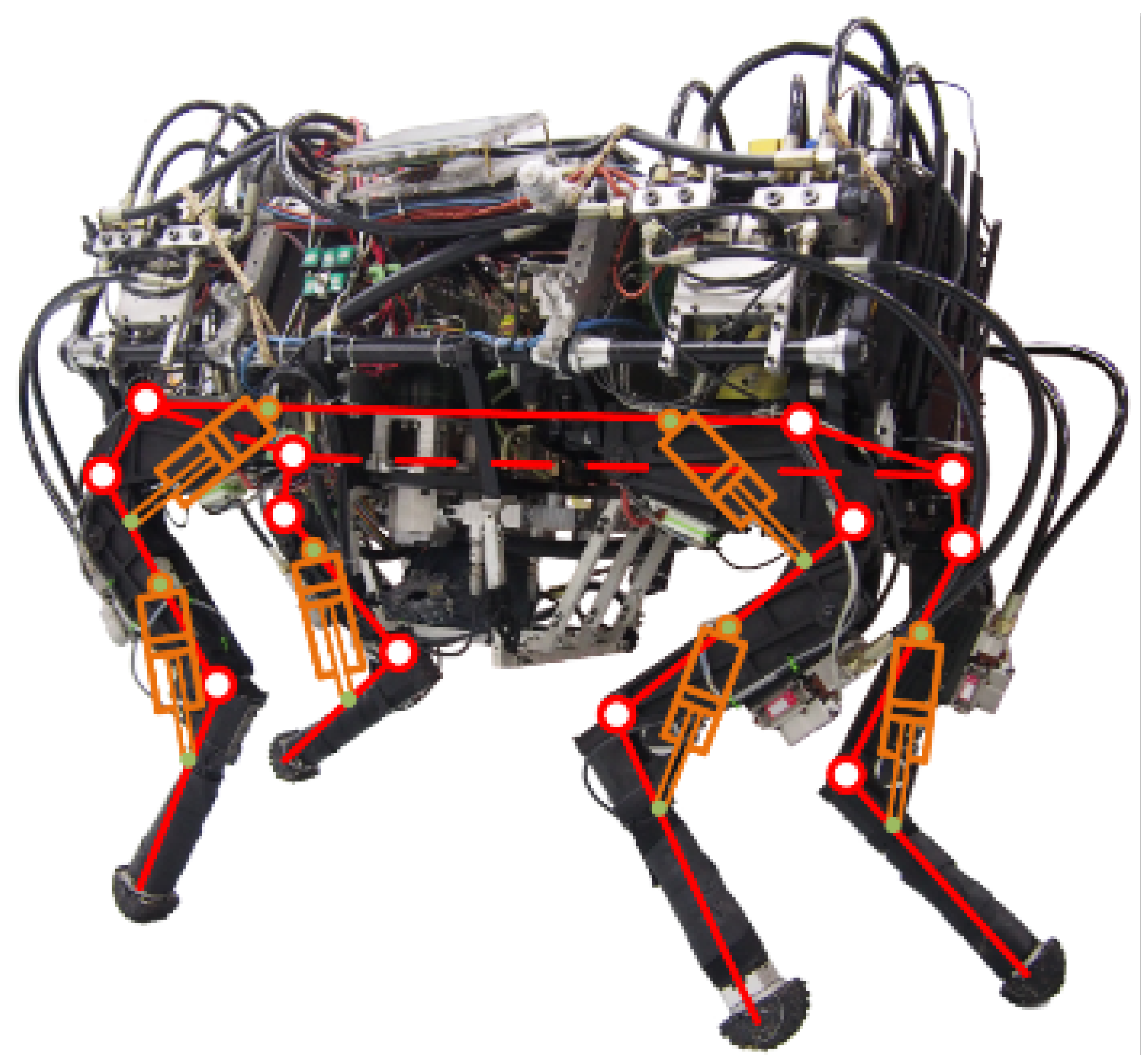
Unfortunately, for the hydraulic quadruped platform, as shown in Figure 1 [28], its hydraulic hoses and hydraulic cylinders cannot be accurately modeled into the MRB floating-based dynamics formula [29]. In addition, in conjunction with the inherent strong nonlinear characteristics of hydraulic systems, it is difficult to use whole-body dynamics for the control of hydraulic quadruped robot prototypes with the large model error. Kundesma, Atlas team leader of Boston Dynamics, mentioned that by leveraging the flexibility and richness of the MRB Dynamics, the Atlas prototype could achieved a series of extraordinary actions, such as leaps, bounds, and backflips, with the help of centroidal dynamics [30]. However, details of the latest work have not been released.

Figure 1.
Hydraulic quadruped robot platform with multiple non-modelable hydraulic hoses and hydraulic drive units. This work consider the leg link with a hydraulic actuator as a single rigid body. The red lines indicate the general dynamics model of floating-based multiple rigid body. Reprinted with permission from ref. [28] 2022 IEEE.
Based on the above, this paper presents an optimal torque control scheme gathering centroidal dynamics and model error compensation (MEC) for a real hydraulic quadruped platform, EHbot. Firstly, the leg link with a hydraulic actuator is considered as a single rigid body. A centroidal dynamics model is derived for the quadruped robot. Based on that, an intrinsic connection between the centroidal coordinates and the whole-body behavior in generalized coordinate space can be formulated and provide a dynamics model for torque control. To avoid the problem of poor robustness of model-based torque control caused by model inaccuracies, such as non-modelable hydraulic components, linearization, disturbances, etc., a MEC approach based on a low-gain PD feedback controller is introduced and projected to configuration space. Combining desired motion and force trajectories generated by a high-level planner, a torque control generated by the multi-objective quadratic programming (MQP) optimization allows robustness tracking target motion (CoM, torso, and foot-end trajectories) and ground reaction forces (GRFs) simultaneously under large model errors. Simulations and experiments were carried out on the EHbot. Finally, the results validate the effectiveness of the proposed torque control algorithm.
The contributions of this work are organized as follows: (i) a centroidal dynamics model is derived for quadruped robots via the change rate of the centroidal momentum, which is linearly associated with the generalized coordinates of the quadruped robot. (ii) We formulate a MEC to robustly address model errors caused by non-modelable hydraulic components, linearization, unexpected disturbances, etc. (iii) Gathering the centroidal dynamics and MEC for trajectory tracking described by generalized coordinates, an MQP torque control scheme is developed for motion and force tracking simultaneously, which can be successfully applied to the real quadruped platform, EHbot. Overall, the proposed optimal torque control scheme enables the quadruped robots to improve the tracking performance and be robust against model inaccuracies.
The remaining sections are outlined as follows. Section 2 introduces the centroidal dynamics model for quadruped robots. In Section 3, the details of the proposed MEC algorithms are presented. On this basis, we design an MQP-based torque controller for both motion and force tracking in Section 4. Several tests are carried out in simulations and on the EHbot, and the results are discussed in Section 5. Finally, the paper is summarized in Section 6.
2. Centroidal Dynamics Formulation
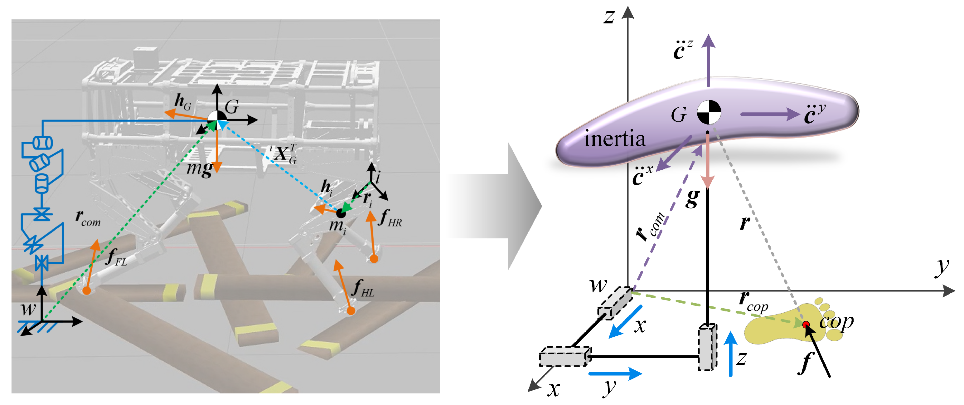
As depicted in Figure 2, the MRB dynamics expressed at the CoM has a distinct advantage that it matches the simplified inverted pendulum model, which is a commonly used template model serving the motion generators.
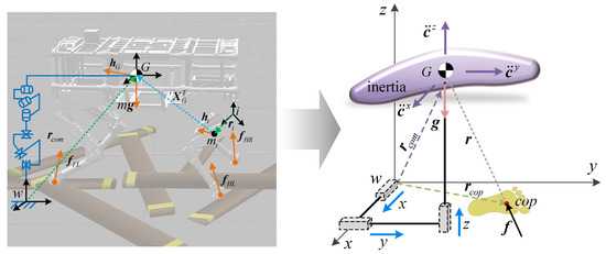
Figure 2.
Floating-based quadruped robot and its simplified template model, which has significant model error due to simplification for use in motion generators.
For each single-rigid-body (SRB) link on a quadruped robot, the linear momentum can be expressed as:
where denotes the linear momentum of link i. and represent the mass and velocity of link i, respectively.
To correlate with the Denavit–Hartenberg (D-H) coordinate system and the generalized coordinates of the quadruped robot, it is convenient to assign a fixed frame numbered 0 and non-inertial frames numbered from 1 to N that are attached to each link of the tree-structure topology of the quadruped robot. On the basis of recursive computation, the CoM velocity of link i can be rewritten as:
where is the linear velocity of the origin of frame i, represents the angular velocity of the link i with respect to frame i. denotes the position vector connecting the origin of frame i to the CoM of link i.
Similarly, the angular momentum of link i can be expressed as:
where and represent the angular momentum and inertia tensor of link i.
Using spatial notation, the angular momentum and linear momentum of link i can be expressed as:
with
where and represent the spatial momentum and spatial inertia of link i, is the skew-symmetric cross-product matrix. is unit diagonal matrix.
The generalized coordinates and generalized velocities of quadruped robots are usually described in configuration space, which facilitates the signal collection and dynamics analysis. Based on the generalized velocity of the quadruped robot, the SRB spatial velocity can be further rewritten as:
where Jacobian matrix represents a linear mapping of the generalized velocity into the spatial velocity of link i.
Therefore, the whole-body centroidal momentum of the quadruped robot aggregates the momentum of all the links projected at the CoM, which is expressed as:
with
where represents the centroidal momentum of the system. represents a spatial transformation matrix from link i to centroidal frame G, is the centroidal momentum matrix (CMM). denotes generalized coordinate vector.
The dynamics equation of the system can be expressed as:
where is the net external force vector acting on the centroidal point.
Equation (9) projects the whole-body dynamics of a tree-structure topology of the quadruped robot onto its CoM, thus capturing the relationship between the net external forces and the generalized coordinate states. Therefore, it provides a simplified whole-body dynamics model for force control of quadruped robots.
Generally, the equations of motion of quadruped robots can be expressed in terms of the generalized coordinates, velocities, and accelerations:
where represents the generalized inertia matrix. denotes the centrifugal and Coriolis forces. is the vectors of gravitational force. The generalized constraint forces is mapped to the joint actuated torques through the constraint Jacobian that describes constraints, denotes the number of legs in contact. is a selection matrix that selects which DoFs are actuated, and it is expressed as:
Decoupling the dynamics into floating-based and actuated components. Equation (10) can be rewritten hereafter as:
The first row of the Equation (12) is the force balance equation considering only the floating-based torso of the quadruped robot. Assuming there is no gravity and the floating-based torso remains actuated, the net external wrench acting on the torso can be expressed as [31]:
where is used to select the top portion of the full Equation (12). The net external force acting on the floating torso, which is equivalent to the virtual wrench (force and moment) generated by a virtual model attached on the torso. denotes a mapping of the generalized velocity of the torso and the spatial velocity described in the fixed frame.
Let , and:
Combined with (9), the net external wrench acting on the centroidal frame G can be expressed as:
where denotes a spatial projection transform for the net external wrench, from torso frame to centroidal frame.
Therefore, the following equation holds:
Substituting (16) into (9), the whole-body centroidal dynamics of the quadruped robot can be calculated. Figure 3 shows the transformation diagram of the whole-body centroidal dynamics formulation for quadruped robots.
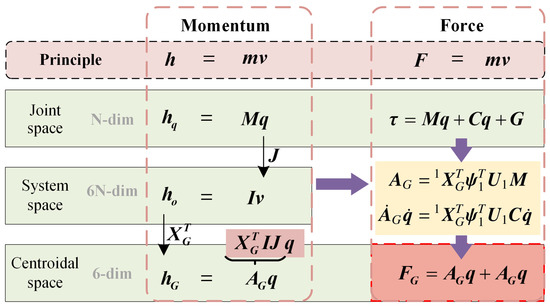
Figure 3.
Transformation diagram of the whole-body centroidal dynamics formulation for quadruped robots.
Based on the conservation of momentum, the linear and angular momentum of each link in the quadruped robot is mapped to the centroidal frame. With the relationship between momentum and force, the derivative of the momentum is used to formulate the whole-body centroidal dynamics, which provides a simplified model for quadruped torque control.
3. Model Error Compensation
Simplified models, such as linear inverted pendulum, single rigid body, etc., are used as template models for motion planning of the legged robots. However, there are some significant model errors, including: (i) inertia matrix errors aggregated from inaccurate measurements of each link, (ii) non-modelable hydraulic components, such as hydraulic hoses, cylinders and transmission parts, (iii) noises of position sensors and revolute joints with radial clearance for a physical platform. In this section, three PD compensations for CoM, torso, and foot-end trajectory tracking under model errors are introduced in details.
3.1. CoM Trajectory Compensation
Based on the axis of the centroidal frame parallel to that of the inertial frame, the net external wrench acting on the centroidal frame of the quadruped robot can be directly described by the operational space wrench of the system:
To prevent the robot from being unstable due to the accumulation of model errors in centroidal motion tracking, a PD feedback compensation mechanism is introduced into (17) for disturbance rejection, which can be rewritten as:
where and represent the proportional gains for angular and linear trajectory tracking, respectively. and represent the derivative gains for angular and linear trajectory tracking in operational space, respectively. c, and are the reference position velocity and acceleration of the centroidal point specified by a high-level motion generator. Superscript denotes the measured states.
Therefore, the desired change rate of the centroidal momentum and a PD feedback compensation are combined for centroidal momentum commands calculation.
3.2. Torso Trajectory Compensation
The desired torso posture is commonly described in operational space. An explicit mapping from operational space to the executed joint space is required to guarantee the precise control of the torque in executed joint space to the torso trajectories in operational space. Naturally, the Jacobian matrix defines a transformation mapping between the velocity described in operational space and that described in joint space.
The acceleration in operational space can be then expressed as:
Therefore, the relationship between the torso acceleration in operational space and the generalized velocity and acceleration in joint space is:
where represents the desired acceleration of the torso posture in operational space. is a constant matrix, which is equal to . So, .
Specified in a form similar to the PD compensation of the centroidal motion, the acceleration of the torso trajectory can be expressed as:
where and represent the proportional and derivative gains for torso trajectory tracking in operational space, respectively.
3.3. Foot-End Trajectory Compensation
The foot-end trajectory is planned in the operational space as well. Jacobian mapping is necessary for the foot-end trajectory planned in operational space and the generalized coordinates in joint space. In terms of MEC for foot-end trajectory, a similar PD feedback formulation for torso trajectory tracking is introduced. The desired foot-end acceleration is hereafter expressed as:
where represents the foot-end trajectory in operational space. denotes the Jacobian matrix of the foot-end. and represent the proportional and derivative gains for foot-end trajectory in operational space, respectively.
It should be emphasized that the interaction between the foot-end and terrain is regarded as point-contact support. Unlike the six-dimensional elements consisting of linear and angular trajectory tracking of the torso, there are only linear elements in the foot-end trajectory. Therefore, the Jacobian of each foot-end is just the linear mapping portion. Formulation of the four legs of the quadruped robot in a unified manner, the Jacobian matrix of the foot-end is .
4. MQP Torque Control
In order to achieve the whole-body dynamic behaviors and track the spatial motion of the CoM, torso, foot-end, as well as the GRFs, a multi-objective optimization algorithm is necessary for the calculation of joint torque. The torque control can be optimized by solving a standard QP problem with a general form as follows:
where the Hessian matrix and gradient vector are used to define any quadratic objective functions on the vector of decision variables . The matrix-vector couples and define inequality and equality constraints, respectively.
The generalized accelerations, joint torques, and GRFs are coupled to each other. In this work, the decision variables are expressed as:
Without loss of generality, the objective expression is expressed in the least squares optimization form:
Back to the standard form, the Hessian matrix and gradient term of the objective function can be expressed as , . With
where denotes the weights, expressing the relative importance among several certain desired behaviors.
4.1. Objective Functions
With the introductions of MEC for CoM, torso and foot-end trajectories and the reference GRFs tracking, the multiple objectives that can be plugged into (28) are listed as follows:
(1) Centroidal motion
(2) Torso motion
(3) Foot-end motion
(4) Directly GRFs tracking
To ensure the whole-body dynamics behaviors of quadruped robots in real-time, the reference GRFs described here are specified by analytical [32] or optimized approaches [33]. The objective function that penalizes deviation from the reference GRFs is expressed as:
(5) Change in torques
In order to smooth the commands of torques and GRFs and avoid high-frequency oscillations in the commands, we penalize changes in torques and GRFs .
(6) Change in GRFs
It should be noted that the weight should be specified for the desired behavior detailed above.
4.2. Constraints
(1) Friction cone and unilateral limits
There are foot-ground friction cone and unilateral contact constraints for each leg (the normal GRF is not less than 0). The GRFs constraints for each leg can be expressed as:
where the top four rows of the matrix represent the convex polyhedral approximation of the friction cone constraints of contact foot i. In this work, friction cones have been approximated as pyramids, which allows us to formulate them as a QP optimization. The last set is a unilateral constraint of the normal forces.
Noting that the reference GRFs optimized by foot force distributions have taken the friction constraints into account. The reference GRFs and the unknown GRFs in the decision variables are not completely equivalent. Therefore, it is necessary to consider the anti-slip friction cone constraints for the torque optimization.
(2) Joint torque limits
(3) Floating-based inverse dynamics
(4) Swing-phase GRFs
Ignoring the inertia force wrapped around the foot force sensor parts, the GRF of each leg equals zero when it is in the air.
Substituting the above objective functions and constraints into the QP paradigm in (25), the joint torque is regarded as torque feed-forward , which can be optimized using open-source QP solvers, such as IPopt [34], QPOASES [35], and QuadProg++ libraries [36].
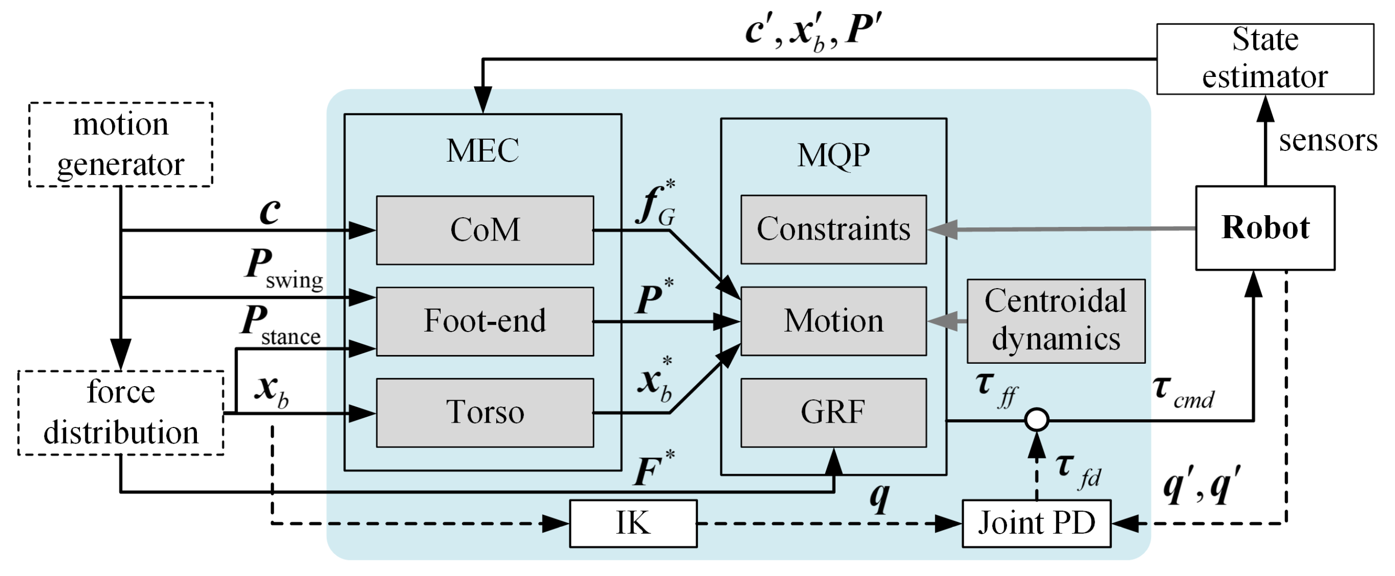
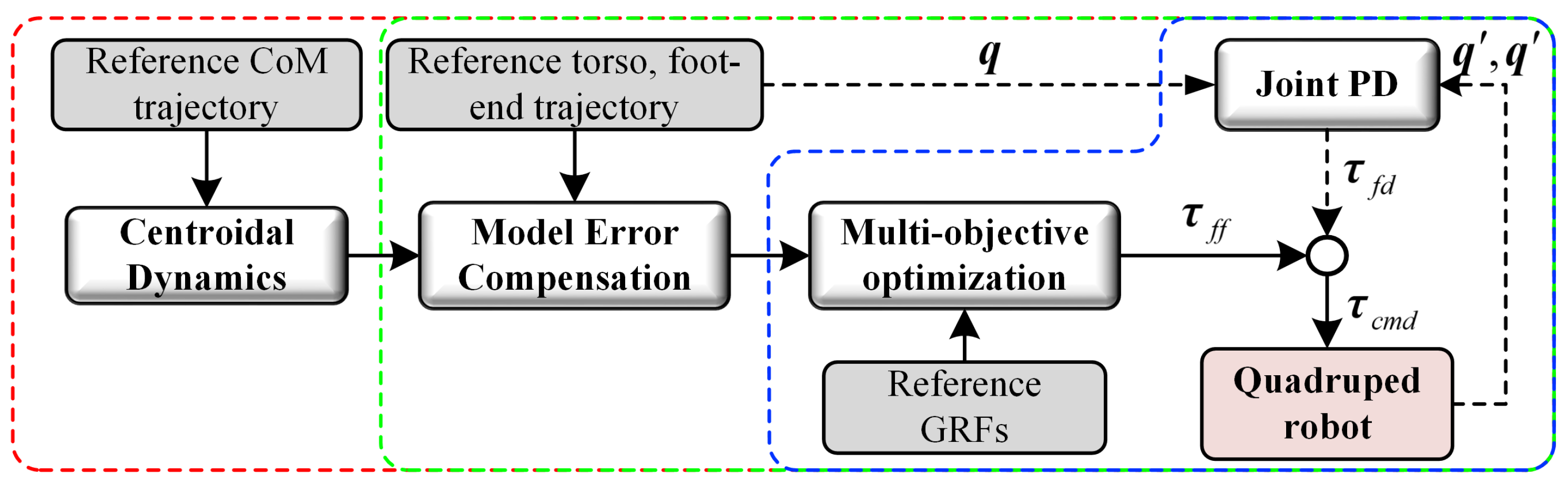
The optimal torque control scheme is depicted in Figure 4. We have noticed that the motion trajectory generated by a motion generator and the reference GRFs obtained through a foot force distribution are exerted as the target for the joint torque control algorithms. Combined with joint space constraint equations, and finally, the feed-forward solution of joint torque has been realized. In addition, a low-gain joint-space PD feedback controller is introduced to further compensating for the model inaccuracies. Therefore, the total joint torque commands can be obtained:
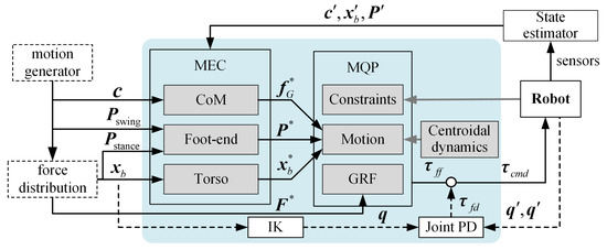
Figure 4.
Optimal joint torque control scheme for quadruped robots.
It is worth noting that the coupled in the optimal torque control algorithm is defined as the decision variables. However, only the joint torque is taken as the output commands, joint accelerations, and generalized constraint forces are not the input for actuation. The purpose of this method is to establish a unified mechanical mapping relationship between the strongly coupled generalized accelerations, GRFs and joint torques, so as to ensure that the joint torque can better track the motion and force at the same time.
5. Results
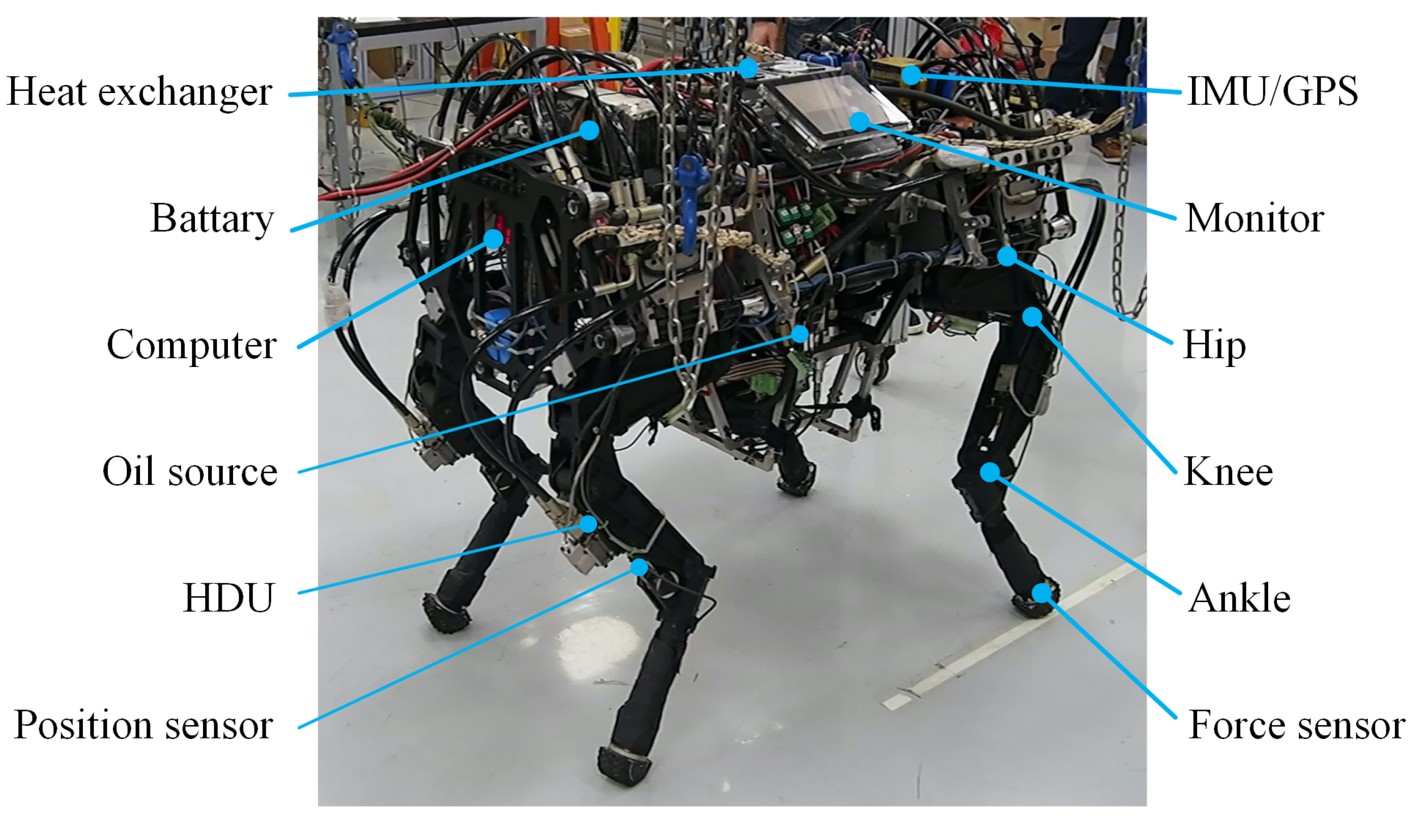
5.1. Experimental Setup
A hydraulically driven quadruped robot, EHbot, was used in our experiment. As shown in Figure 5, EHbot weights approximately 150 kg, is fully-torque controlled and equipped with the position sensors, force sensors, and an inertial measurement unit (IMU). An on-board hydraulic oil source system was customized for the hydraulic system. DoFs with three activities on each leg are named as hip abduction/adduction (HAA), knee flexion/extension(KFE) and ankle flexion/extension(AFE). The foot-end can be therefore placed in a three-dimensional space. In total, 12 active DoFs are driven by the customed hydraulic drive units (HDUs) [37].

Figure 5.
The overall structure of the electro-hydraulic quadruped platform, EHbot, with 12 hydraulically-actuated DoFs and various sensors.
In order to validate the effectiveness of the proposed optimal torque control algorithm, we have carried out the preliminary simulation on the physical simulator robot operating system (ROS) and Gazebo [38]. The simulation is implemented on a computer with 2.3 GHz quadcore Intel Core i5-6300HQ processor. The open source qpOASES-3.2.0 library [35] is used for optimization.
5.2. Simulations and Experiments
We have demonstrated various tests in simulations and then conducted experiments on a hydraulic quadruped platform, EHbot, to validate the advantages in two perspectives of the multi-objective optimal torque control scheme we proposed. A video of the results of the simulations and experiments can be found in https://www.youtube.com/watch?v=BbdXTgwV1L0&ab_channel=YapengShi (accessed on 29 January 2022).
Firstly, the tests were carried out using three controllers: (i) Joint high-gain PD control with refined parameters tuning, (ii) joint low-gain PD + MEC, and (iii) joint low-gain PD + MEC+ centroidal dynamics-based CoM trajectory tracking (CD). It should be noted that controller (iii) is the optimal torque control scheme that we proposed. The low-gain PD parameters of controllers (ii) and (iii) are the same. The high-gain PD parameters of controller (i) are carefully tuned for walking purposes. The block diagram of the proposed three different controllers is depicted in Figure 6.
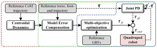
Figure 6.
Block diagram of the three different controllers exerted on simulations and a real hydraulic quadruped platform. Blue dotted area indicates a pure joint PD controller with refined parameters tuning. Red dotted area indicates the proposed optimal torque control scheme composed of joint low-gain PD + MEC+ centroidal dynamics-based CoM trajectory tracking (CD). Joint low-gain PD + MEC controller is encapsulated by green dotted area.
Controllers (i), (ii), and (iii) are encapsulated by blue, green, and red dotted areas, respectively. We assume that the torso position and CoM trajectory are treated equivalently in the following cases, considering the deviations are caused by the inaccurate model.
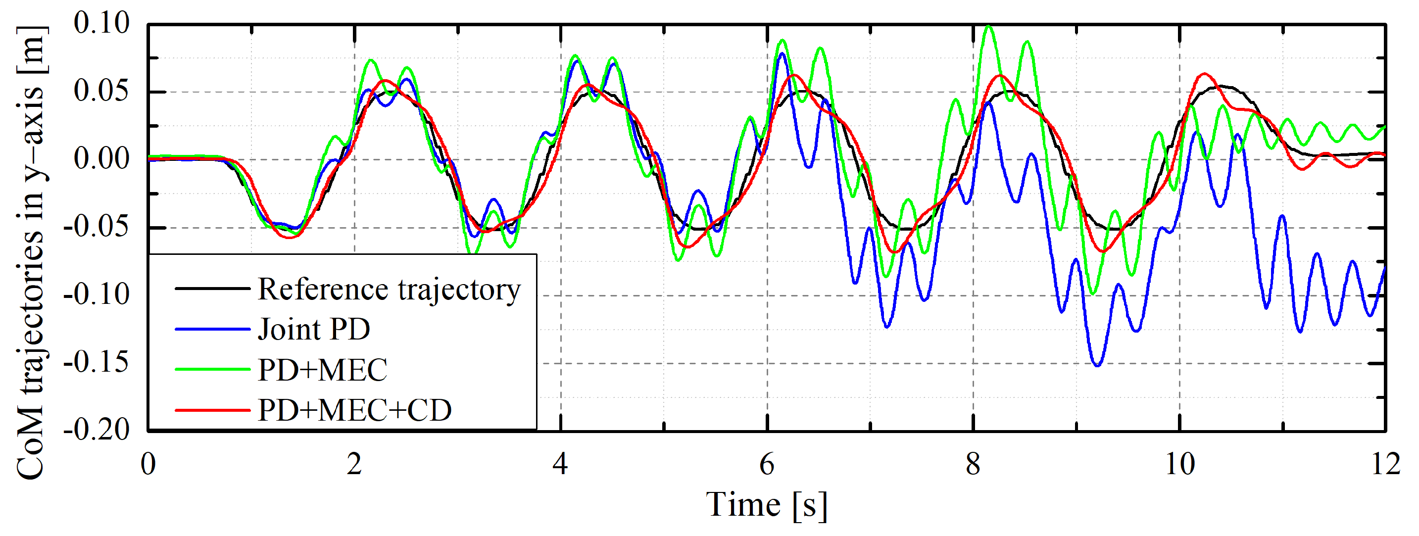
Under the same reference CoM trajectory generated by an MPC motion generator [39], Figure 7 demonstrates the quadruped-CoM trajectory tracking results under the three different controllers.
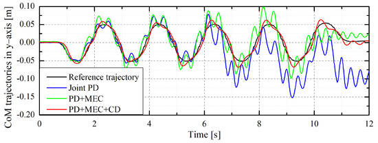
Figure 7.
Comparison of the quadruped-CoM tracking results in the lateral direction (y-axis) under the three different controllers. The black line indicates the reference lateral quadruped-CoM trajectory; the green line is the actual CoM trajectory under controller (i); the green and red lines indicate the actual CoM trajectories under controllers (ii) and (iii).
In addition, the corresponding quantitative comparison of the quadruped-CoM tracking error under the three controllers is further discussed. The maximum deviation, endpoint value deviation, and root mean square error (RMSE) are illustrated in Table 1.

Table 1.
Quantitative comparison of quadruped-CoM tracking with three controllers.
It can be seen from the simulation results that quadruped-CoM trajectory tracking has similar performance under the joint PD controller and the PD + MEC controller implemented at the beginning. However, due to the influence of model inaccuracies and foot-end slippage, the maximum deviation between the actual trajectory (blue line) and reference value (black line) reaches 0.1381 m. Additionally, the endpoint deviation reaches 0.095 m as time goes on. This is reasonable for a joint PD controller since not only is there no quadruped-CoM trajectory tracking feed-forward introduced, but also no error compensation term for the CoM trajectory. In the PD + MEC controller, the quadruped-CoM trajectory tracking of error compensation is introduced with torso position and CoM trajectory treated equivalently.
However, due to the large inertia of the quadruped robot system, it is difficult to eliminate the influence of inertial forces of the system by the torso trajectory tracking with Jacobian quasi-static mapping. Thereby, the CoM trajectory (green line) oscillates significantly and the RMSE reaches 0.022 m. With the CoM trajectory tracking on the basis of the centroidal dynamics, multi-objective torque controller (iii) is formulated by embedding centroidal dynamics and model error compensation terms. This allows for better tracking performance of the actual CoM trajectory (red line). The corresponding deviation is an order of magnitude lower than that of the joint PD controller.
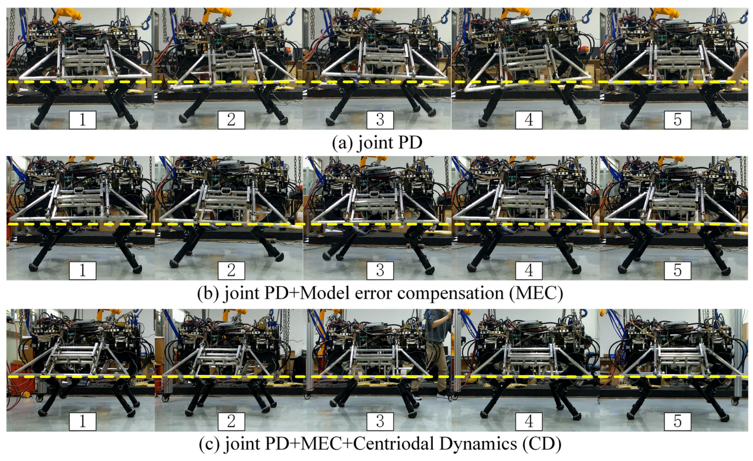
To further validate the performance of our multi-objective torque control algorithm, the proposed three different controllers are implemented on the real quadruped platform, EHbot. Snapshots of experimental trials with three controllers are demonstrated in Figure 8.
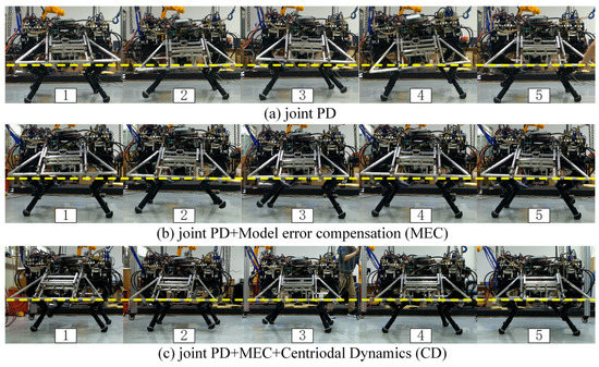
Figure 8.
Snapshots of experimental trials with three controllers.
Correspondingly, the comparison results of roll angles of the torso are depicted in Figure 9.
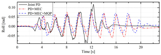
Figure 9.
Comparison of the roll angle profiles of the quadruped platform with the proposed joint PD controller (black solid line), PD + MEC controller (red dashed dot line), and PD + MEC + CD controller (blue dashed line).
In the case of joint PD controller implementation only, the amplitude of the roll angle profile (black solid line) of the quadruped platform gradually increases during walking due to the contact impacts and model inaccuracies. The roll angle reaches a maximum of 0.12 rad at about 12.3 s (amplitude fluctuation is higher than 0.2 rad) and then cannot maintain stability. The reason for the subsequent decrease in roll angle fluctuations in the figure is that it is artificially stopped to prevent the robot from falling. After the introduction of the MEC algorithm, the large fluctuation of the roll angle caused by foot-ground impacts and model inaccuracies disappeared. However, without the tracking for the reference CoM trajectory, the torso tracking based on quasi-static Jacobian mapping cannot eliminate the effect of the large inertial forces of the system. As a result, the amplitude of the roll angle fluctuates above 0.13 rad.
The proposed multi-objective optimal torque control scheme establishes the mathematical relationship between the whole-body dynamics and the CoM trajectory by centroidal dynamics. The effect of the inertia forces of each link of the system is considered in the tracking of the CoM trajectory. The problem of the inertia forces is solved. As can be seen from the figure, the amplitude of roll angle fluctuation is controlled within 0.11 rad. The results of the comparison tests demonstrate that the proposed controllers can effectively improve the stability performance for real hydraulic quadruped platforms under large model inaccuracies.
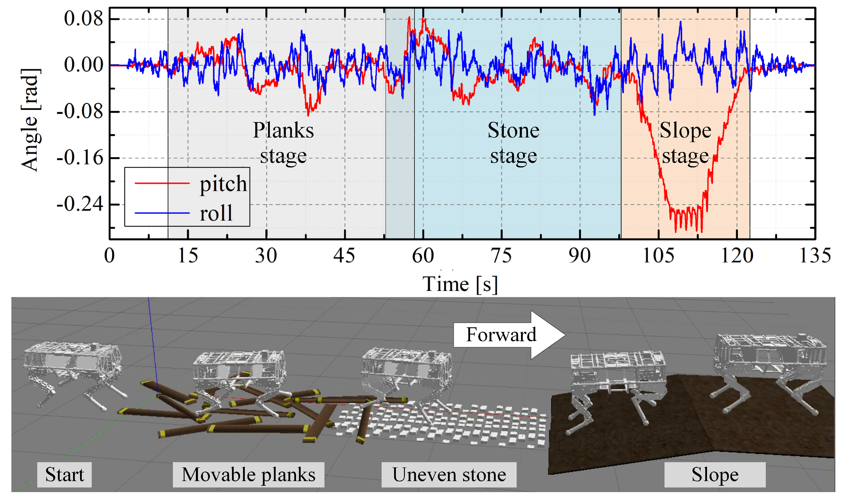
The second validation is the simulation of the quadruped robot traversing over complex terrain to further demonstrate the effectiveness of the proposed scheme. Three different terrains are set in the simulation: (i) movable planks with a thickness of 3 cm randomly stacked, (ii) uneven stone road with a height of about 5 cm, and (iii) slope. The snapshots of the quadruped robot walking over the complex terrain at 0.3 m/s are demonstrated in Figure 10.

Figure 10.
Simulation results of the quadruped robot traversing over three different terrains. The upper figure demonstrates the snapshot of the quadruped robot traversing over three on complex terrains. The low figure shows the results of pitch (red line) and roll (blue line) angle profiles of the torso during walking.
It should be highlighted that the quadruped robot is walking blindly without prior environment information input. The quadruped robot can traverse over planks and uneven stones, climb up the slope, and then reach your destination steadily. The torso angles of the quadruped robot while walking are depicted in Figure 10. We noticed that the angle of the robot fluctuates in a narrow range. The maximum fluctuation of pitch angle (red solid line) and roll angle (blue solid line) over rough terrain is less than 0.09 rad and 0.07 rad, respectively. During climbing, the pitch angle reaches about 0.24 rad because of slope, but the fluctuation range still remains small during locomotion.
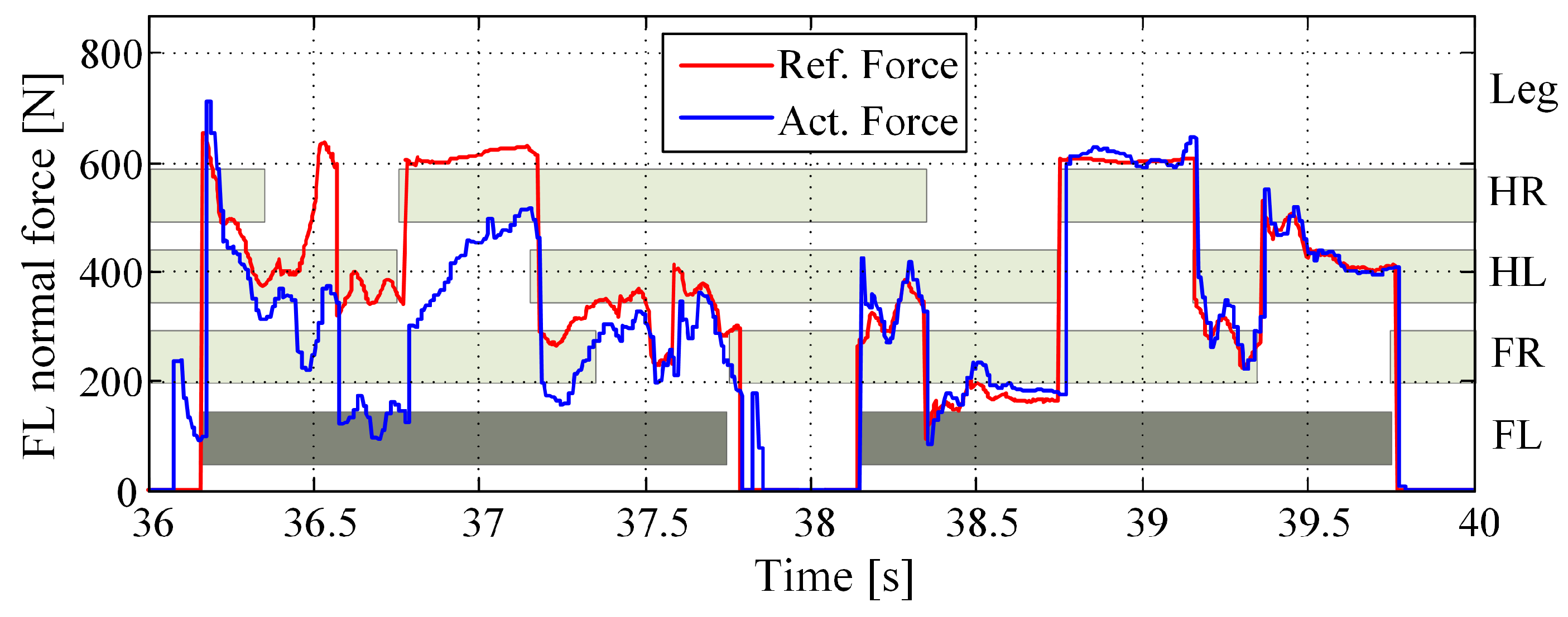
Figure 11 shows the tracking results of the fore-left (FL) normal force during 36∽40 s. Bar patterns indicate the stance phase of each leg. HR, HL, and FR represent the hind-right, hind-left, and fore-right leg, respectively. We show the results for the FL leg only. Because the results for the other legs are qualitatively the same. When the actual normal force deviates significantly from the reference one, the torso posture fluctuates dramatically thereafter. It can be seen that the multi-objective optimal torque scheme we proposed has the ability to reduce the force deviation and restore the torso posture within one step.
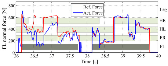
Figure 11.
The results of the fore-left (FL) normal force of the quadruped robot walking on movable planks with the proposed torque control scheme. HR, HL, and FR represent the hind-right, hind-left, and fore-right leg, respectively. Bar patterns indicate the stance duration. Red line indicates the reference normal forces. Blue line is the actual normal forces.
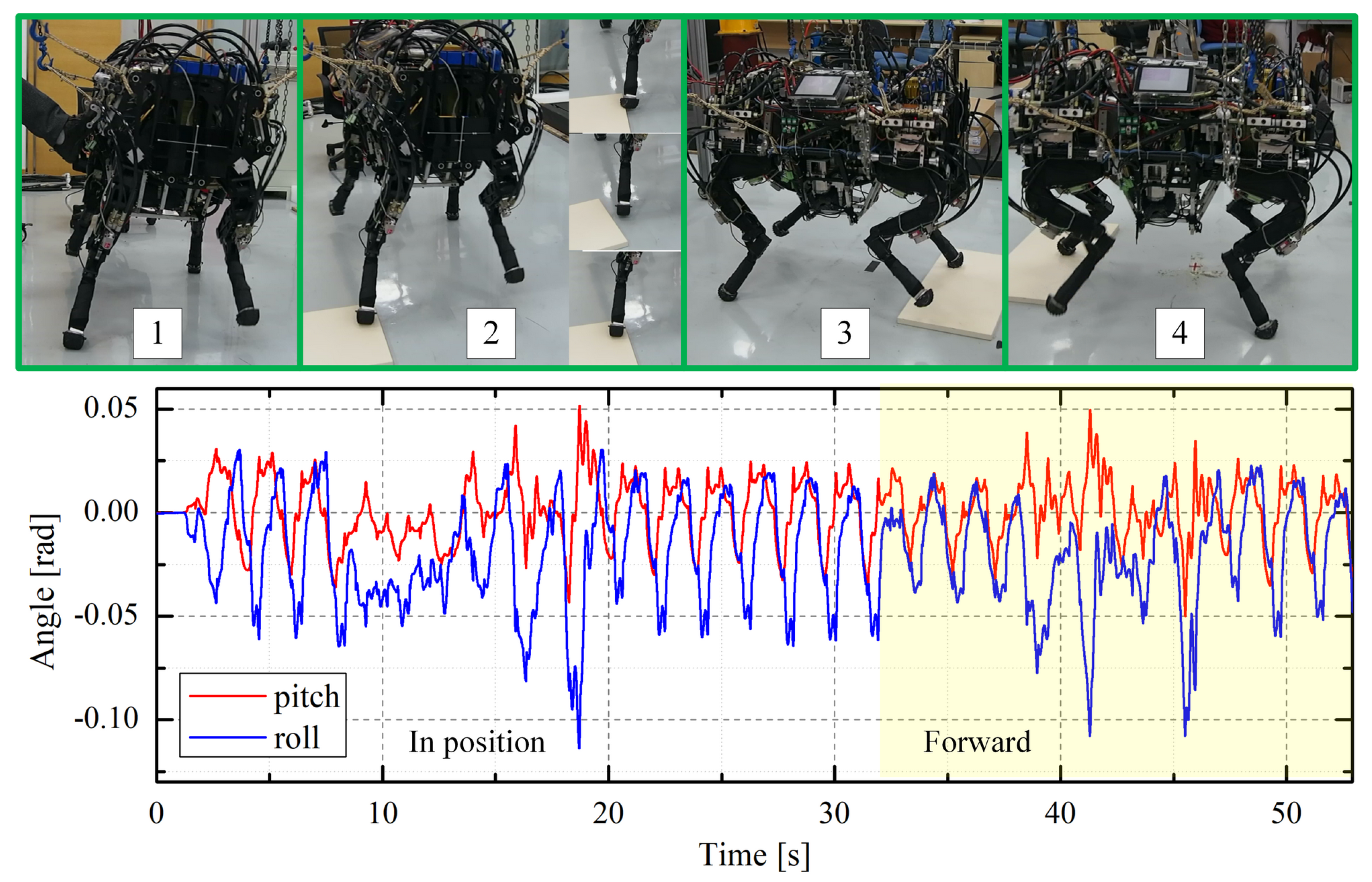
In the third validation, the proposed optimal torque scheme was implemented on a real hydraulic quadruped platform, EHbot, with the environment of external disturbances and a 2 cm plank on the ground. The plank was taken and placed under the foot-end artificially to validate the dynamic stability of the quadruped robot. The pitch and roll angle profiles and experimental snapshots of the quadruped robot during walking are shown in Figure 12.
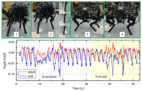
Figure 12.
Snapshots of the quadruped walking with unexpected external and terrain disturbances. There are 4 stages of the entire experimental trial. The first 2 stages are the quadruped platform stepped in place with external and terrain disturbances. The quadruped platform walking forward is demonstrated in the last 2 stages.
In stage 1 of the upper figure, unexpected external disturbances were exerted by kicking the torso laterally to test the performance of the push recovery of the quadruped robot. In stage 2, a plank with a height of 2 cm was repeatedly taken and placed on the FR foot-end of the quadruped platform. In stage 3 and 4, the quadruped platform walking over the plank (yellow shaded area in the lower Figure 12) was carried out. It can be seen that the quadruped robot has the ability to remain robust under both lateral external and terrain disturbances with the proposed torque control scheme. From the figure profiles, During the entire experimental trial, the maximum amplitudes of the pitch and roll angle profiles are about 0.05 rad and 0.12 rad, respectively.
Through the series of tests discussed above, comparison and rough terrain disturbances were implemented in simulations as well as experiments on a real hydraulic quadruped platform, EHbot. The results demonstrate that a similar performance can be observed in simulations and real quadruped experiments. These tests validate the proposed torque control scheme is robust to large model inaccuracies and improves the performance of the overall system.
6. Conclusions
In this paper, we present a multi-objective optimal torque control scheme for hydraulic quadruped robots. The scheme uses both centroidal dynamics and MEC algorithms. Centroidal dynamics modelled projects the dynamics behaviors to centroidal frame to follow the centroidal motion. In addition, MEC algorithm is developed to deal with model inaccuracies caused by non-modelable elements, linearization, and disturbances. The motion of the CoM, torso, and foot-end trajectories are further projected in joint space. Hence, a multi-objective QP problem is formulated to coordinate track the motion and GRFs simultaneously. With the satisfaction of all constraints, the optimal torque control scheme is proposed. Finally, a series of simulations and experimental trials were conducted on a hydraulic quadruped robot through comparison and disturbances tests. The results demonstrate that the torque control scheme we proposed can effectively improve the stability and robustness to model inaccuracies.
This work mainly focus on the application of QP-based torque control scheme to the hydraulic physical system with large inaccuracies. In the near future, we hope to incorporate hydraulic actuators and a hydraulic control system (e.g., force command tracking and synchronization control of the hydraulic actuators) for better performance.
Author Contributions
Conceptualization, Y.S. and K.B.; methodology, Y.S.; software, L.Y.; validation, Y.S., X.H. and K.B.; investigation, B.Y. and L.Y.; resources, M.L.; data curation, W.Z., Y.S. and G.P.; writing—original draft preparation, X.H. and W.Z.; writing—review and editing, Y.S.; supervision, M.L.; project administration, B.Y.; funding acquisition, K.B., M.L. and G.P. All authors have read and agreed to the published version of the manuscript.
Funding
The authors disclosed receipt of the following financial support for the research, authorship, and/or publication of this article: authors gratefully thank the support of the National Natural Science Foundation of China (Grant No. 51905465 and Grant No. 52122503), the National Key R&D Program of China (Grant No. 2018YFB2000700), the Science and Technology Program of Yangzhou, China (Grant No. YZ2021004).
Institutional Review Board Statement
Not applicable.
Informed Consent Statement
Not applicable.
Data Availability Statement
Not applicable.
Conflicts of Interest
The authors declare no conflict of interest.
References
- Focchi, M.; Pucci, D.; Del Prete, A. Bridging the Gap between the Lab and the Real World: Future Perspectives for Legged Robots. Front. Robot. AI 2020, 7, 194. [Google Scholar] [CrossRef] [PubMed]
- Ba, K.X.; Song, Y.H.; Yu, B.; Wang, C.Y.; Li, H.S.; Zhang, J.X.; Ma, G.L. Kinematics correction algorithm for the LHDS of a legged robot with semi-cylindrical foot end based on V-DOF. Mech. Syst. Signal Process. 2022, 167, 108566. [Google Scholar] [CrossRef]
- Semini, C.; Barasuol, V.; Focchi, M.; Boelens, C.; Emara, M.; Casella, S.; Villarreal, O.; Orsolino, R.; Fink, G.; Fahmi, S.; et al. Brief Introduction to the Quadruped Robot HyQReal; Istituto di Robotica e Macchine Intelligenti (I-RIM): Rome, Italy, 2019. [Google Scholar]
- Li, J.; You, B.; Ding, L.; Yu, X.; Li, W.; Zhang, T.; Gao, H. Dual-Master/Single-Slave Haptic Teleoperation System for Semiautonomous Bilateral Control of Hexapod Robot Subject to Deformable Rough Terrain. IEEE Trans. Syst. Man Cybern. Syst. 2021. [Google Scholar] [CrossRef]
- Chen, T.; Rong, X.; Li, Y.; Ding, C.; Chai, H.; Zhou, L. A compliant control method for robust trot motion of hydraulic actuated quadruped robot. Int. J. Adv. Robot. Syst. 2018, 15, 1729881418813235. [Google Scholar] [CrossRef] [Green Version]
- Righetti, L.; Buchli, J.; Mistry, M.; Schaal, S. Inverse dynamics control of floating-base robots with external constraints: A unified view. In Proceedings of the 2011 IEEE International Conference on Robotics and Automation, Shanghai, China, 9–13 May 2011; pp. 1085–1090. [Google Scholar]
- Ba, K.X.; Song, Y.H.; Shi, Y.P.; Wang, C.Y.; Ma, G.L.; Wang, Y.; Yu, B.; Yuan, L.P. A novel one-dimensional force sensor calibration method to improve the contact force solution accuracy for legged robot. Mech. Mach. Theory 2022, 169, 104685. [Google Scholar] [CrossRef]
- Du, W. Motion Generation of Four-Limb Robots Using Whole-Body Torque Control. Ph.D. Thesis, Sorbonne Université, Paris, France, 2020. [Google Scholar]
- Sugihara, T.; Morisawa, M. A survey: Dynamics of humanoid robots. Adv. Robot. 2020, 34, 1338–1352. [Google Scholar] [CrossRef]
- Jung, J.; Kim, D.; Park, J. Operational Space Control Framework for Torque Controlled Humanoid Robots with Joint Elasticity. In Proceedings of the 2019 IEEE/RSJ International Conference on Intelligent Robots and Systems (IROS), The Venetian Macao, Macau, 4–8 November 2019; pp. 3063–3069. [Google Scholar]
- Khatib, O. A unified approach for motion and force control of robot manipulators: The operational space formulation. IEEE J. Robot. Autom. 1987, 3, 43–53. [Google Scholar] [CrossRef] [Green Version]
- Park, J.; Khatib, O. Contact consistent control framework for humanoid robots. In Proceedings of the 2006 IEEE International Conference on Robotics and Automation (ICRA 2006), Orlando, FL, USA, 15–19 May 2006; pp. 1963–1969. [Google Scholar]
- Lee, Y.; Kim, S.; Park, J.; Tsagarakis, N.; Lee, J. A whole-body control framework based on the operational space formulation under inequality constraints via task-oriented optimization. IEEE Access 2021, 9, 39813–39826. [Google Scholar] [CrossRef]
- Lee, Y.; Tsagarakis, N.; Lee, J. Study on operational space control of a redundant robot with un-actuated joints: Experiments under actuation failure scenarios. Nonlinear Dyn. 2021, 105, 331–344. [Google Scholar] [CrossRef]
- Bledt, G.; Kim, S. Extracting legged locomotion heuristics with regularized predictive control. In Proceedings of the 2020 IEEE International Conference on Robotics and Automation (ICRA), Paris, France, 31 May–31 August 2020; pp. 406–412. [Google Scholar]
- Moro, F.L.; Sentis, L. Whole-body control of humanoid robots. In Humanoid Robotics: A Reference; Goswami, A., Vadakkepat, P., Eds.; Springer: Dordrecht, The Netherlands, 2019. [Google Scholar]
- Henze, B. Whole-Body Control for Multi-Contact Balancing of Humanoid Robots: Design and Experiments; Springer Nature: Cham, Switzerland, 2021; Volume 143. [Google Scholar]
- Bellicoso, C.D.; Jenelten, F.; Fankhauser, P.; Gehring, C.; Hwangbo, J.; Hutter, M. Dynamic locomotion and whole-body control for quadrupedal robots. In Proceedings of the 2017 IEEE/RSJ International Conference on Intelligent Robots and Systems (IROS), Vancouver, BC, Canada, 24–28 September 2017; pp. 3359–3365. [Google Scholar]
- Ramuzat, N.; Buondonno, G.; Boria, S.; Stasse, O. Comparison of Position and Torque Whole-Body Control Schemes on the Humanoid Robot TALOS. In Proceedings of the 2021 20th International Conference on Advanced Robotics (ICAR), Ljubljana, Slovenia, 6–10 December 2021; pp. 785–792. [Google Scholar]
- Kim, D.; Di Carlo, J.; Katz, B.; Bledt, G.; Kim, S. Highly dynamic quadruped locomotion via whole-body impulse control and model predictive control. arXiv 2019, arXiv:1909.06586. [Google Scholar]
- Orin, D.E.; Goswami, A.; Lee, S.H. Centroidal dynamics of a humanoid robot. Auton. Robot. 2013, 35, 161–176. [Google Scholar] [CrossRef]
- Orin, D.E.; Goswami, A. Centroidal momentum matrix of a humanoid robot: Structure and properties. In Proceedings of the 2008 IEEE/RSJ International Conference on Intelligent Robots and Systems, Nice, France, 22–26 September 2008; pp. 653–659. [Google Scholar]
- Shah, P.; Meduri, A.; Merkt, W.; Khadiv, M.; Havoutis, I.; Righetti, L. Rapid convex optimization of centroidal dynamics using block coordinate descent. In Proceedings of the 2021 IEEE/RSJ International Conference on Intelligent Robots and Systems (IROS), Prague, Czech Republic, 27 September–1 October 2021; pp. 1658–1665. [Google Scholar]
- Wensing, P.M.; Orin, D.E. Generation of dynamic humanoid behaviors through task-space control with conic optimization. In Proceedings of the 2013 IEEE International Conference on Robotics and Automation, Karlsruhe, Germany, 6–10 May 2013; pp. 3103–3109. [Google Scholar]
- Dai, H.; Valenzuela, A.; Tedrake, R. Whole-body motion planning with centroidal dynamics and full kinematics. In Proceedings of the 2014 IEEE-RAS International Conference on Humanoid Robots, Madrid, Spain, 18–20 November 2014; pp. 295–302. [Google Scholar]
- Liu, M.; Qu, D.; Xu, F.; Zou, F.; Di, P.; Tang, C. Quadrupedal robots whole-body motion control based on centroidal momentum dynamics. Appl. Sci. 2019, 9, 1335. [Google Scholar] [CrossRef] [Green Version]
- Jo, J.; Oh, Y. Impedance Control of Humanoid Walking on Uneven Terrain with Centroidal Momentum Dynamics Using Quadratic Programming. In Proceedings of the 2020 IEEE/RSJ International Conference on Intelligent Robots and Systems (IROS), Las Vegas, NV, USA, 24 October 2020–24 January 2021; pp. 3525–3530. [Google Scholar]
- Shi, Y.; Wang, P.; Wang, X.; Zha, F.; Jiang, Z.; Guo, W.; Li, M. Bio-inspired equilibrium point control scheme for quadrupedal locomotion. IEEE Trans. Cogn. Dev. Syst. 2018, 11, 200–209. [Google Scholar]
- Mastalli, C.; Havoutis, I.; Focchi, M.; Caldwell, D.G.; Semini, C. Motion planning for quadrupedal locomotion: Coupled planning, terrain mapping, and whole-body control. IEEE Trans. Robot. 2020, 36, 1635–1648. [Google Scholar] [CrossRef]
- Kuindersma, S. Recent Progress on Atlas, the World’s Most Dynamic Humanoid Robot. Available online: https://youtu.be/EGABAx52GKI (accessed on 30 December 2021).
- Wensing, P.M.; Orin, D.E. Improved computation of the humanoid centroidal dynamics and application for whole-body control. Int. J. Humanoid Robot. 2016, 13, 1550039. [Google Scholar] [CrossRef] [Green Version]
- Wang, P.; Shi, Y.; Zha, F.; Jiang, Z.; Wang, X.; Li, Z. An analytic solution for the force distribution based on Cartesian compliance models. Int. J. Adv. Robot. Syst. 2019, 16, 1729881419827473. [Google Scholar] [CrossRef] [Green Version]
- Di Carlo, J.; Wensing, P.M.; Katz, B.; Bledt, G.; Kim, S. Dynamic locomotion in the mit cheetah 3 through convex model-predictive control. In Proceedings of the 2018 IEEE/RSJ International Conference on Intelligent Robots and Systems (IROS), Madrid, Spain, 1–5 October 2018; pp. 1–9. [Google Scholar]
- Wächter, A.; Biegler, L.T. On the implementation of an interior-point filter line-search algorithm for large-scale nonlinear programming. Math. Program. 2006, 106, 25–57. [Google Scholar] [CrossRef]
- Ferreau, H.J.; Kirches, C.; Potschka, A.; Bock, H.G.; Diehl, M. qpOASES: A parametric active-set algorithm for quadratic programming. Math. Program. Comput. 2014, 6, 327–363. [Google Scholar] [CrossRef]
- Bellicoso, C.D. Optimization-Based Planning and Control for Multi-Limbed Walking Robots. Ph.D. Thesis, ETH Zurich, Zurich, Switzerland, 2019. [Google Scholar]
- Shi, Y.; Li, M.; Zha, F.; Sun, L.; Guo, W.; Ma, C.; Li, Z. Force-controlled Compensation Scheme for PQ Valve-controlled Asymmetric Cylinder used on Hydraulic Quadruped Robots. J. Bionic Eng. 2020, 17, 1139–1151. [Google Scholar] [CrossRef]
- Koenig, N.; Howard, A. Design and use paradigms for gazebo, an open-source multi-robot simulator. In Proceedings of the 2004 IEEE/RSJ International Conference on Intelligent Robots and Systems (IROS)(IEEE Cat. No. 04CH37566), Sendai, Japan, 28 September–2 October 2004; Volume 3, pp. 2149–2154. [Google Scholar]
- Shi, Y.; Wang, P.; Li, M.; Wang, X.; Jiang, Z.; Li, Z. Model predictive control for motion planning of quadrupedal locomotion. In Proceedings of the 2019 IEEE 4th International Conference on Advanced Robotics and Mechatronics (ICARM), Toyonaka, Japan, 3–5 July 2019; pp. 87–92. [Google Scholar]


Publisher’s Note: MDPI stays neutral with regard to jurisdictional claims in published maps and institutional affiliations. |
© 2022 by the authors. Licensee MDPI, Basel, Switzerland. This article is an open access article distributed under the terms and conditions of the Creative Commons Attribution (CC BY) license (https://creativecommons.org/licenses/by/4.0/).