
Theoretical Roughness Modeling of Hard Turned Surfaces Considering Tool Wear


Abstract
:1. Introduction
State of the Art of Surface Roughness and Wear Modeling in Hard Turning
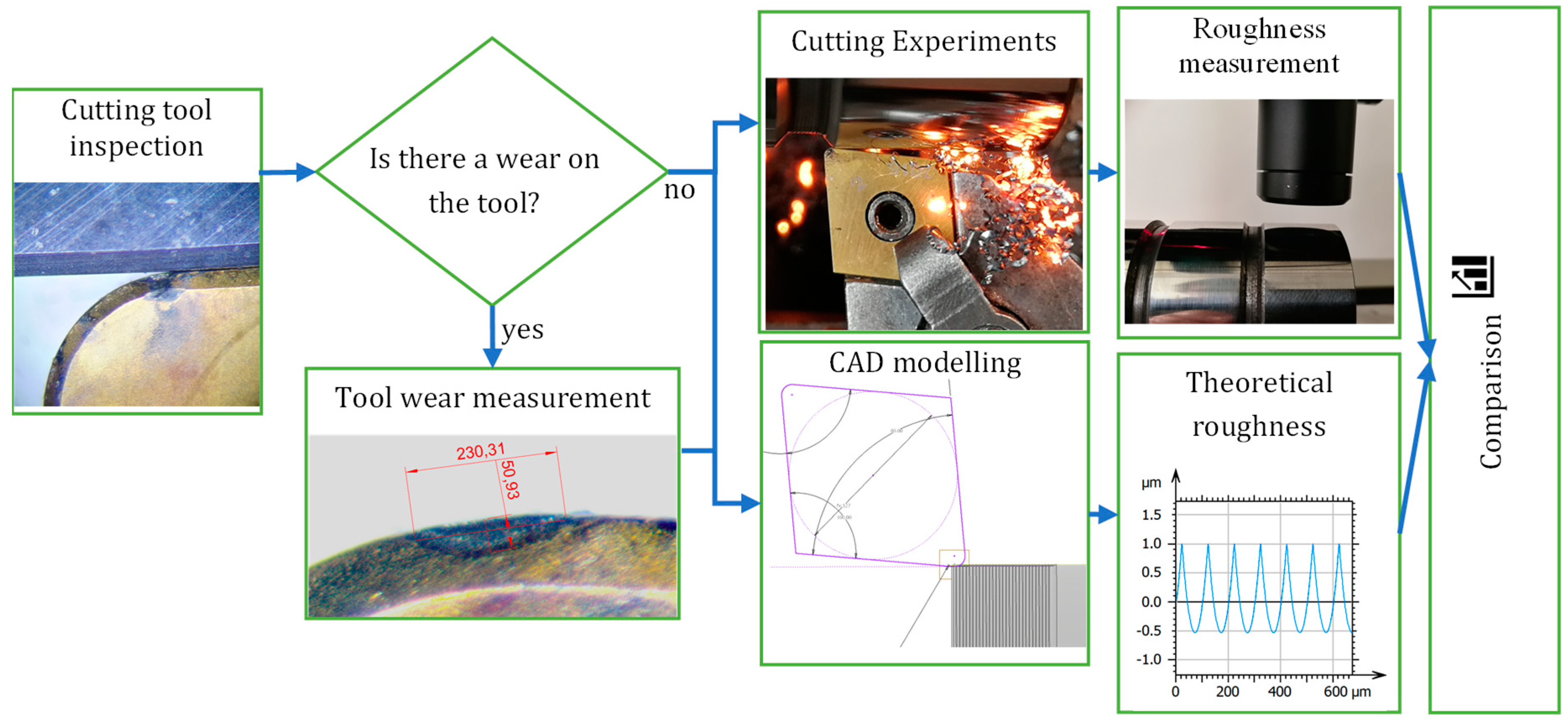
2. Materials and Methods
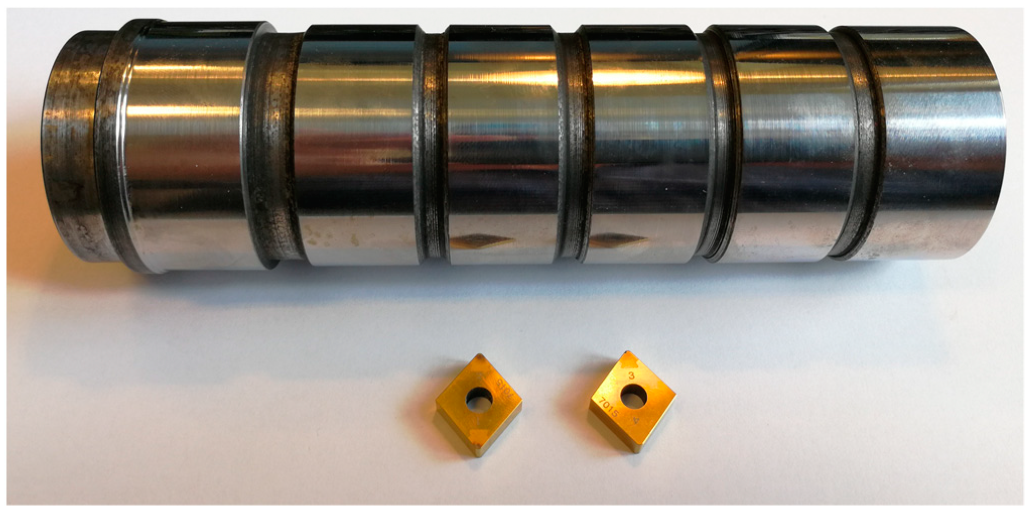
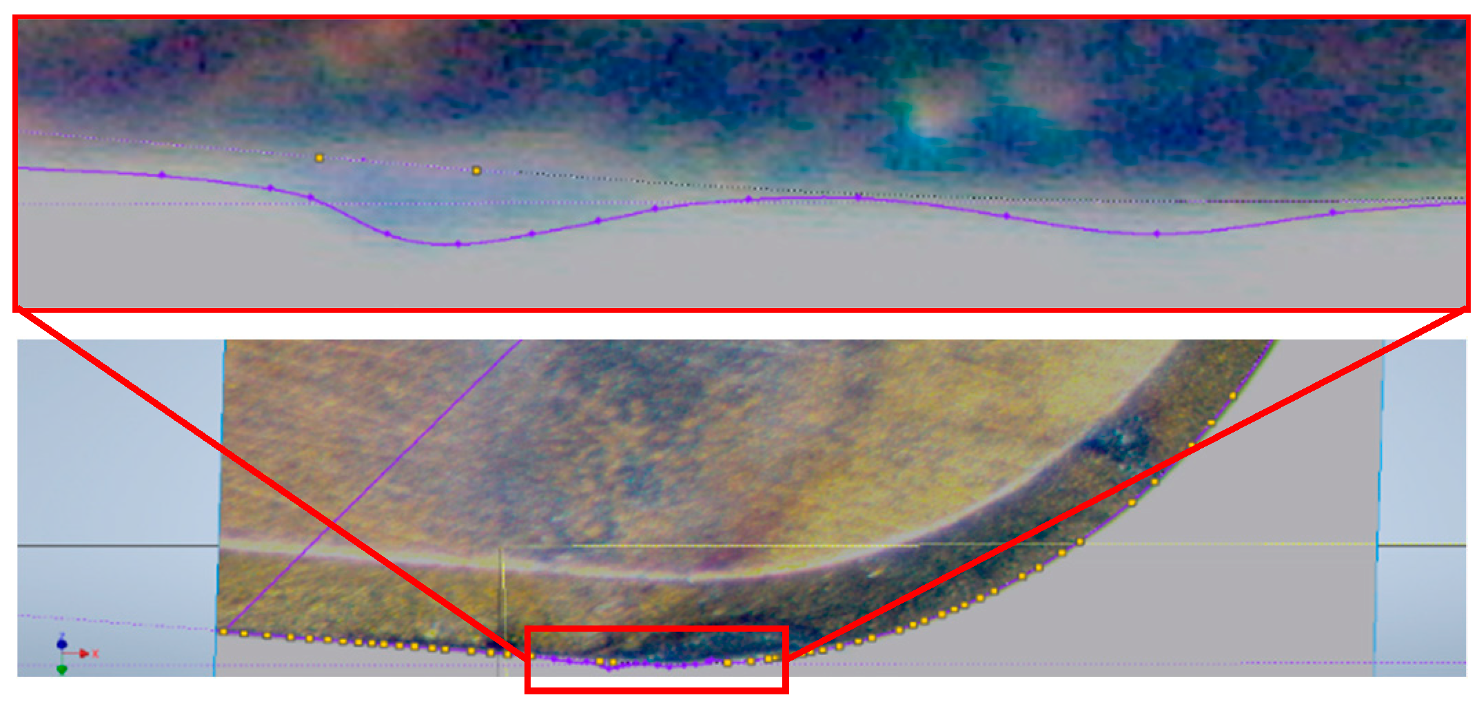
2.1. Investigation Conditions
2.2. Surface Roughness Modeling
- First, the uncut workpiece geometry (in the actual case, it is a cylinder) was modeled in the CAD system (the AutoDesk Inventor software was used in the current work).
- After that, the two-dimensional cutting edge geometry was created in the tool reference plane. This is an ideal representation of the cutting tool edge, without its own irregularities and/or wear characteristics.
- Next, the trajectory of the cutting tool was created on the surface. In the case of turning, it is a helical path, where the value of the pitch of the helix corresponds to the feed per revolution (f) value of the turning process. The axis of the helix is the rotational axis of the workpiece.
- The next step is the actual simulation of the cutting process: the cutting edge geometry is guided along the tool path and the resulting volume is cut from the workpiece material. Thus, the machined surface was obtained. However, it should be noted here that most CAD systems do not allow to intersect the cut volume by itself (self-intersection). This problem can be easily solved by reducing the rotational angle below 360°, and then creating a linear pattern along the rotational axis from the cut volume with the spacing distance of feed (f).
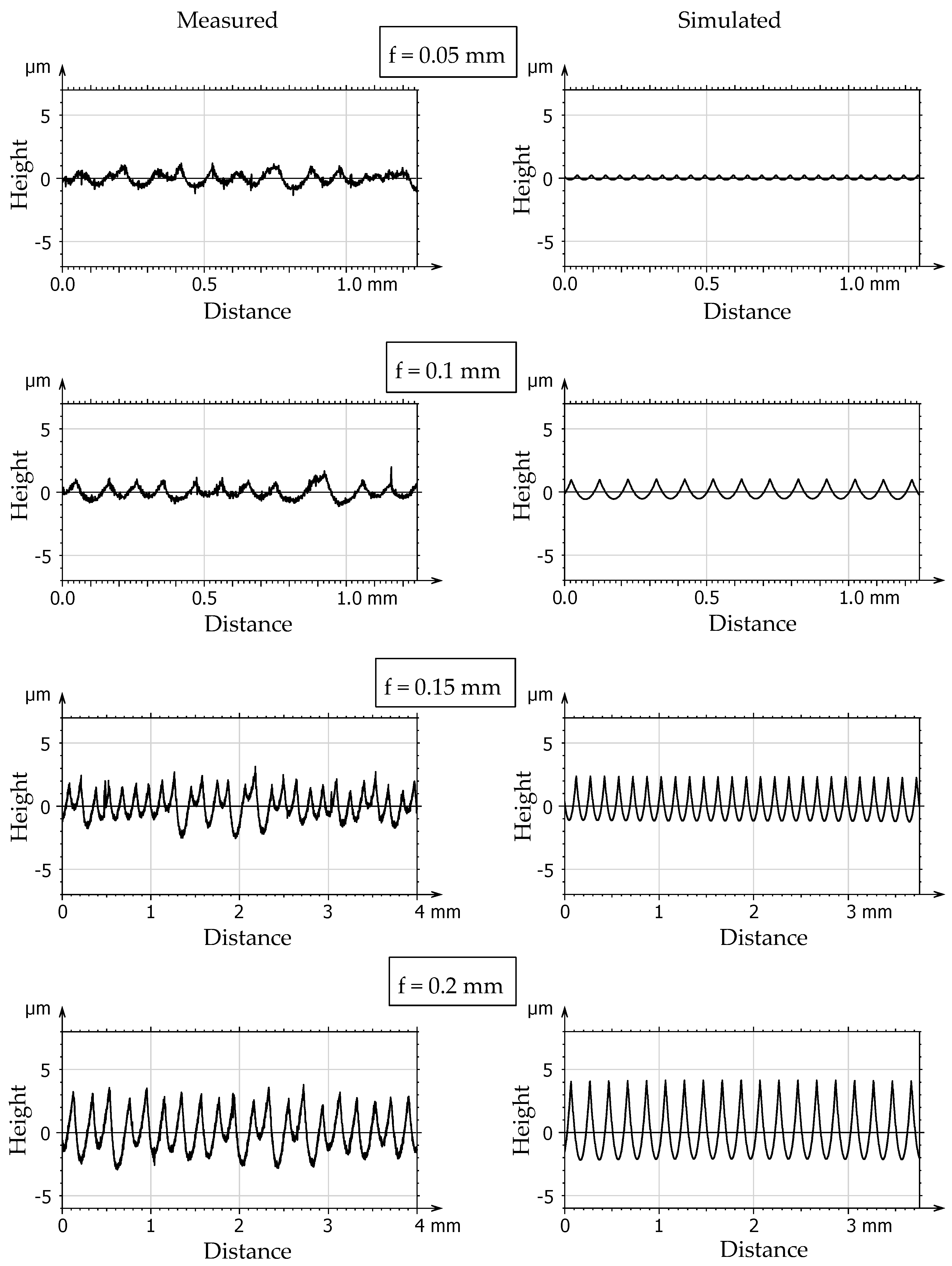
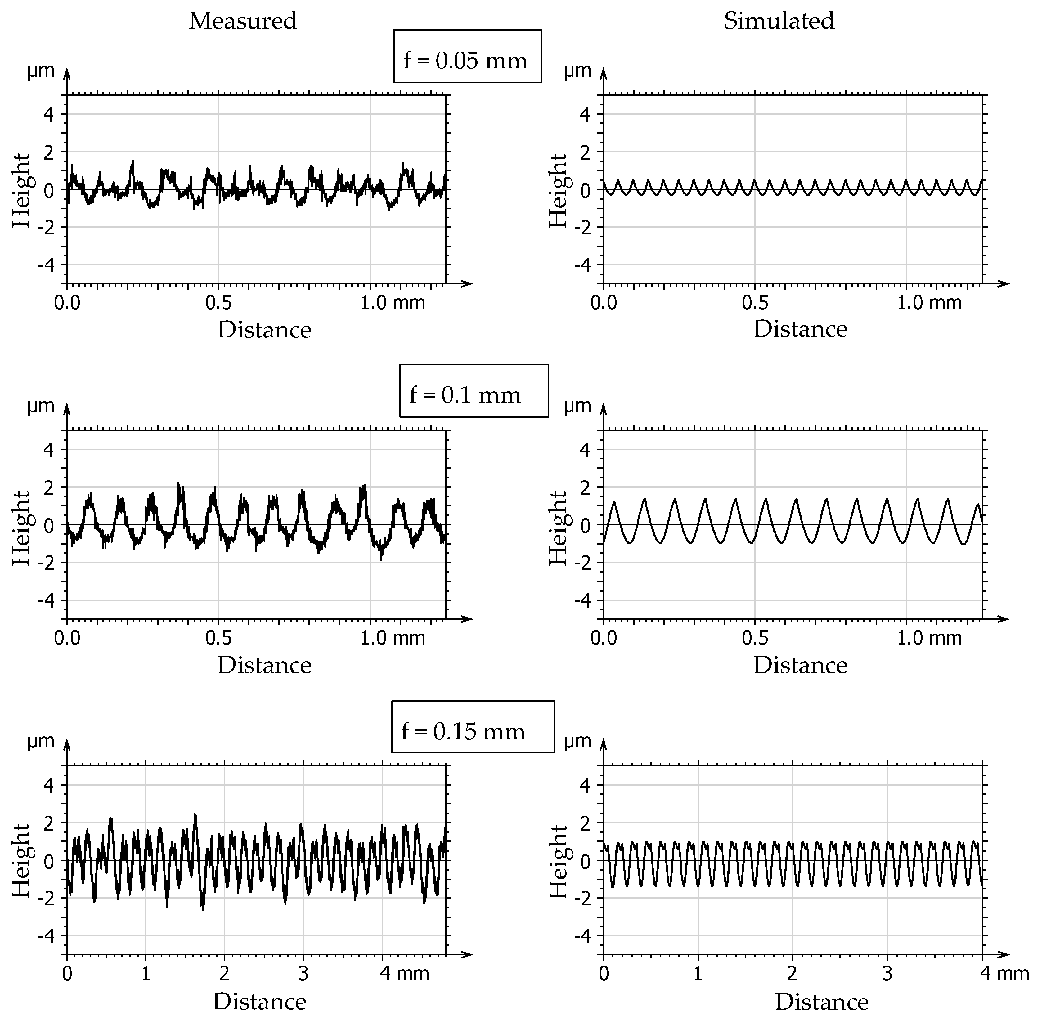
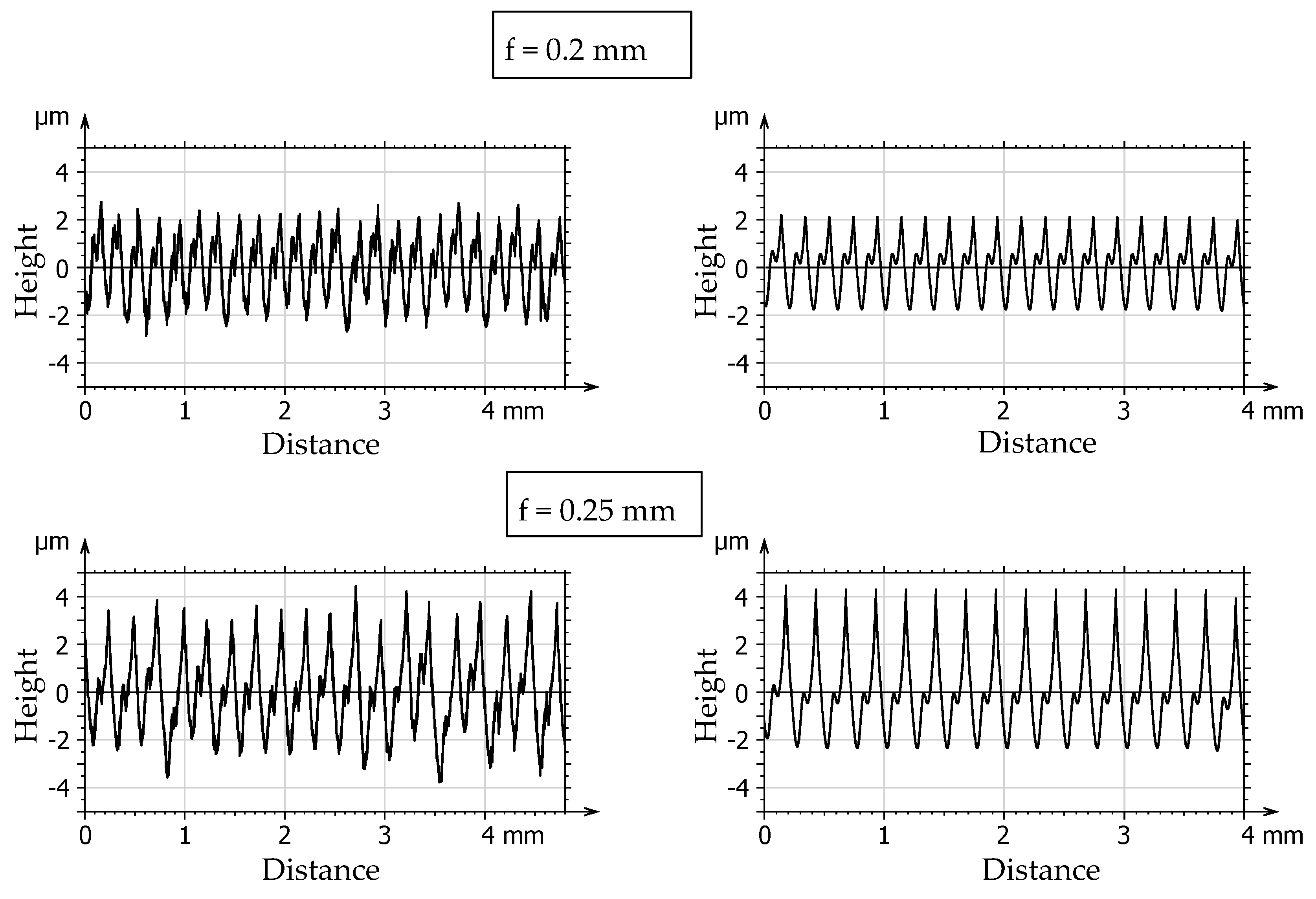
- The next step is to create a so-called measurement line: a measurement plane was defined, which intersects the generated surface in the given radial position, thus cutting out the 2D “measured” profile of the simulated surface. This is basically the theoretical profile, but the points of this profile are not available by default in the CAD system.
- The following step is to query the points of this profile from the CAD system, for which a specially designed interface program (Add-In) had to be developed. There is a programming interface for almost every CAD system, which can be used to interact with it, and to perform various modeling and other tasks.
- This is followed by storing the obtained profile coordinates in an appropriate file format, which can be evaluated later with a dedicated surface analysis software. In the current investigations, the AltiMap (Mountains) software was used, which is developed by Digital Surf Inc. It has its own format for 2D profiles (.pro) and surfaces (.sur) as well, and there is an application programming interface for saving the data points in one of those formats.
- The final step is to load the generated data files into the AltiMap software and evaluate them according to the parameters needed. Thus, the theoretical and the measured data can be evaluated with the same software, with the same method.
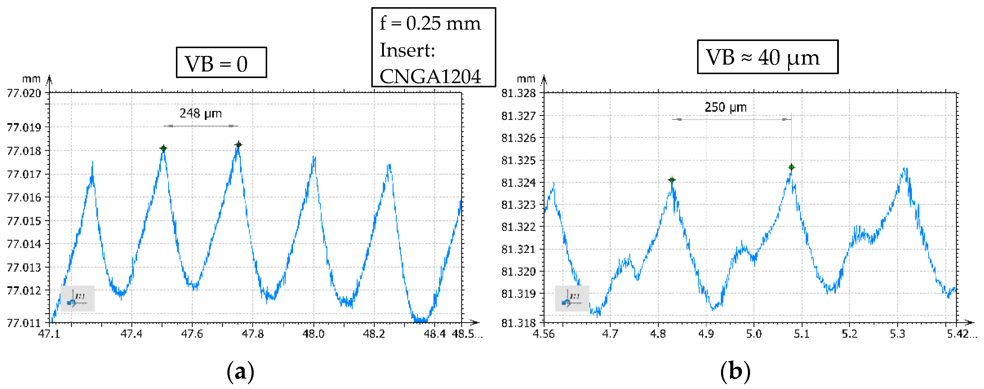
3. Results and Discussion
- SV: Simulated value
- MV: Measured value

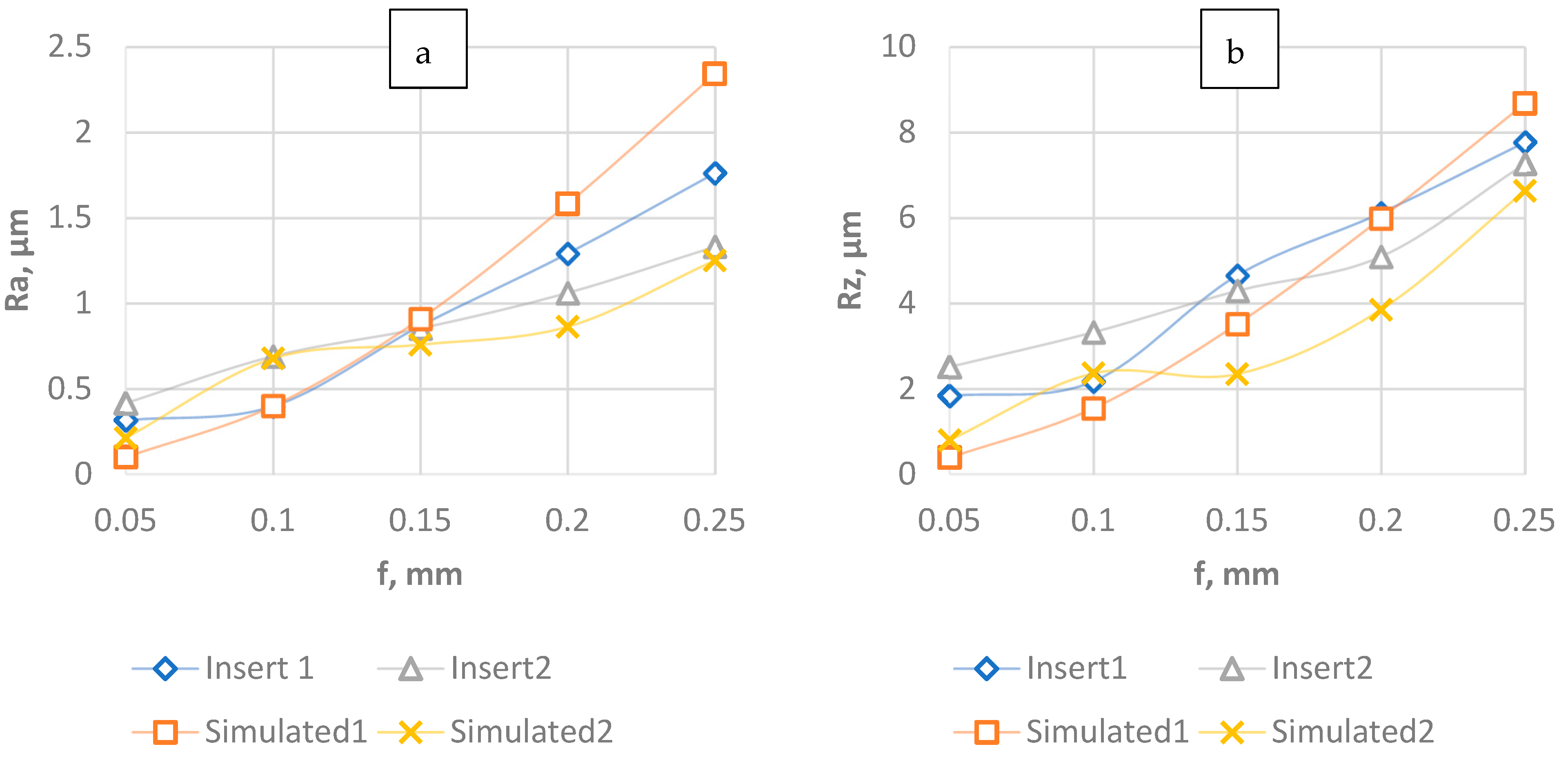
| f, mm | Ra, µm | |||||
|---|---|---|---|---|---|---|
| 0.05 | 0.1 | 0.15 | 0.2 | 0.25 | ||
| Insert1 | Measured | 0.316 | 0.397 | 0.867 | 1.29 | 1.76 |
| Simulated | 0.099 | 0.399 | 0.908 | 1.58 | 2.34 | |
| Error, % | 68.7 | 0.5 | 4.7 | 22.5 | 32.9 | |
| Insert2 | Measured | 0.415 | 0.69 | 0.853 | 1.06 | 1.33 |
| Simulated | 0.212 | 0.677 | 0.7575 | 0.8623 | 1.25 | |
| Error, % | 48.9 | 1.9 | 11.2 | 18.6 | 6 | |
| f, mm | Rz, µm | |||||
|---|---|---|---|---|---|---|
| 0.05 | 0.1 | 0.15 | 0.2 | 0.25 | ||
| Insert1 | Measured | 1.83 | 2.17 | 4.65 | 6.11 | 7.76 |
| Simulated | 0.388 | 1.54 | 3.51 | 5.98 | 8.67 | |
| Error, % | 78.8 | 29 | 24.5 | 2.2 | 11.7 | |
| Insert2 | Measured | 2.51 | 3.32 | 4.29 | 5.09 | 7.26 |
| Simulated | 0.796 | 2.36 | 2.342 | 3.849 | 6.63 | |
| Error, % | 68.3 | 28.9 | 45.4 | 24.4 | 8.7 | |
4. Conclusions
Author Contributions
Funding
Institutional Review Board Statement
Informed Consent Statement
Data Availability Statement
Acknowledgments
Conflicts of Interest
References
- Shihab, S.K.; Khan, Z.A.; Mohammad, A.; Siddiquee, A.N. A Review of Turning of Hard Steels Used in Bearing and Automotive Applications. Prod. Manuf. Res. 2014, 2, 24–49. [Google Scholar] [CrossRef] [Green Version]
- Xu, Q.; Liu, J.; Cai, G.; Jiang, D.; Zhou, J. A Fuzzy Evaluation of Tool Materials in the Turning of Marine Steels. Metals 2021, 11, 1710. [Google Scholar] [CrossRef]
- Thakur, D.G.; Ramamoorthy, B.; Vijayaraghavan, L. Influence of Minimum Quantity Lubrication on the High Speed Turning of Aerospace Material Superalloy Inconel 718. Int. J. Mach. Mach. Mater. 2013, 13, 203–214. [Google Scholar] [CrossRef]
- Kumar, P.; Chauhan, S.R.; Pruncu, C.I.; Gupta, M.K.; Pimenov, D.Y.; Mia, M.; Gill, H.S. Influence of Different Grades of CBN Inserts on Cutting Force and Surface Roughness of AISI H13 Die Tool Steel during Hard Turning Operation. Materials 2019, 12, 177. [Google Scholar] [CrossRef] [PubMed] [Green Version]
- Grzesik, W.; Żak, K.; Kiszka, P. Comparison of Surface Textures Generated in Hard Turning and Grinding Operations. Procedia CIRP 2014, 13, 84–89. [Google Scholar] [CrossRef] [Green Version]
- Kundrak, J.; Karpuschewski, B.; Gyani, K.; Bana, V. Accuracy of Hard Turning. J. Mater. Process. Technol. 2008, 202, 328–338. [Google Scholar] [CrossRef]
- Saini, S.; Ahuja, I.S.; Sharma, V.S. Residual Stresses, Surface Roughness, and Tool Wear in Hard Turning: A Comprehensive Review. Mater. Manuf. Process. 2012, 27, 583–598. [Google Scholar] [CrossRef]
- Musavi, S.H.; Davoodi, B.; Niknam, S.A. Environmental-Friendly Turning of A286 Superalloy. J. Manuf. Process. 2018, 32, 734–743. [Google Scholar] [CrossRef]
- Webster, J.A. Improving Surface Integrity and Economics of Grinding by Optimum Coolant Application, with Consideration of Abrasive Tool and Process Regime. Proc. Inst. Mech. Eng. Part B J. Eng. Manuf. 2007, 221, 1665–1675. [Google Scholar] [CrossRef]
- Kundrák, J.; Varga, G. Use of Coolants and Lubricants in Hard Machining. Tech. Gaz. 2013, 20, 1081–1086. [Google Scholar]
- Sam Paul, P.; Varadarajan, A.S.; Robinson Gnanadurai, R. Study on the Influence of Fluid Application Parameters on Tool Vibration and Cutting Performance during Turning of Hardened Steel. Eng. Sci. Technol. Int. J. 2016, 19, 241–253. [Google Scholar] [CrossRef] [Green Version]
- Gnanadurai, R.; Varadarajan, A. s Investigation on the Effect of Cooling of the Tool Using Heat Pipe during Hard Turning with Minimal Fluid Application. Eng. Sci. Technol. Int. J. 2016, 19, 1190–1198. [Google Scholar] [CrossRef] [Green Version]
- Bartarya, G.; Choudhury, S.K. State of the Art in Hard Turning. Int. J. Mach. Tools Manuf. 2012, 53, 1–14. [Google Scholar] [CrossRef]
- Grzesik, W. A Revised Model for Predicting Surface Roughness in Turning. Wear 1996, 194, 143–148. [Google Scholar] [CrossRef]
- Grzenda, M.; Bustillo, A. The Evolutionary Development of Roughness Prediction Models. Appl. Soft Comput. 2013, 13, 2913–2922. [Google Scholar] [CrossRef]
- Benardos, P.; Vosniakos, G.-C. Prediction Surface Roughness in Machining—Review. Int. J. Mach. Tool Manuf. 2003, 43, 833–844. [Google Scholar] [CrossRef]
- Lu, C. Study on Prediction of Surface Quality in Machining Process. J. Mater. Process. Technol. 2008, 205, 439–450. [Google Scholar] [CrossRef]
- Kovács, G.; Benotsmane, R.; Dudás, L. The Concept of Autonomous Systems in Industry 4.0. Adv. Logist. Syst. 2019, 12, 77–87. [Google Scholar] [CrossRef]
- Gubán, M.; Kovács, G. Industry 4.0 Conception. Acta Tech. Corviniensis-Bull. Eng. 2017, 10, 111. [Google Scholar]
- Liu, L.; Zhang, X.; Wan, X.; Zhou, S.; Gao, Z. Digital Twin-Driven Surface Roughness Prediction and Process Parameter Adaptive Optimization. Adv. Eng. Inform. 2022, 51, 101470. [Google Scholar] [CrossRef]
- Khorasani, A.M.; Yazdi, M.R.S.; Safizadeh, M.S. Analysis of Machining Parameters Effects on Surface Roughness: A Review. Int. J. Comput. Mater. Sci. Surf. Eng. 2012, 5, 68–84. [Google Scholar] [CrossRef]
- Astakhov, V.P. Geometry of Single-Point Turning Tools and Drills; Springer Series in Advanced Manufacturing; Springer: London, UK, 2010; ISBN 978-1-84996-053-3. [Google Scholar]
- Adamczak, S.; Miko, E.; Čuš, F. A Model of Surface Roughness Constitution in the Metal Cutting Process Applying Tools with Defined Stereometry. J. Mech. Eng. 2009, 55, 45–54. [Google Scholar]
- Felhő, C.; Karpuschewski, B.; Kundrák, J. Surface Roughness Modelling in Face Milling. Procedia CIRP 2015, 31, 136–141. [Google Scholar] [CrossRef] [Green Version]
- Taha, Z.; Lelana, H.; Aoyama, H.; Raja Ghazilla, R.A.; Gonzales, J.; Sakundarini, N.; Sutono, S.B. Insert Geometry Effects on Surface Roughness in Turning Process of AISI D2 Steel. J. Zhejiang Univ.-Sci. A 2010, 11, 966–971. [Google Scholar] [CrossRef]
- Zhao, T.; Agmell, M.; Persson, J.; Bushlya, V.; Ståhl, J.E.; Zhou, J.M. Correlation between Edge Radius of the CBN Cutting Tool and Surface Quality in Hard Turning. J. Superhard Mater. 2017, 39, 251–258. [Google Scholar] [CrossRef]
- Zhao, T.; Zhou, J.M.; Bushlya, V.; Ståhl, J.E. Effect of Cutting Edge Radius on Surface Roughness and Tool Wear in Hard Turning of AISI 52100 Steel. Int. J. Adv. Manuf. Technol. 2017, 91, 3611–3618. [Google Scholar] [CrossRef] [Green Version]
- Zak, K. Cutting Mechanics and Surface Finish for Turning with Differently Shaped Cbn Tools. Arch. Mech. Eng. 2017, 64, 347–357. [Google Scholar] [CrossRef] [Green Version]
- Mane, S.; Kumar, S. Analysis of Surface Roughness during Turning of AISI 52100 Hardened Alloy Steel Using Minimal Cutting Fluid Application. Adv. Mater. Process. Technol. 2020, 1–12. [Google Scholar] [CrossRef]
- Selvam, M.D.; Senthil, P. Investigation on the Effect of Turning Operation on Surface Roughness of Hardened C45 Carbon Steel. Aust. J. Mech. Eng. 2016, 14, 131–137. [Google Scholar] [CrossRef]
- Ferreira, R.; Carou, D.; Lauro, C.H.; Davim, J.P. Surface Roughness Investigation in the Hard Turning of Steel Using Ceramic Tools. Mater. Manuf. Process. 2016, 31, 648–652. [Google Scholar] [CrossRef]
- D’Addona, D.M.; Raykar, S.J. Analysis of Surface Roughness in Hard Turning Using Wiper Insert Geometry. Procedia CIRP 2016, 41, 841–846. [Google Scholar] [CrossRef]
- Singh, D.; Rao, P.V. A Surface Roughness Prediction Model for Hard Turning Process. Int. J. Adv. Manuf. Technol. 2007, 32, 1115–1124. [Google Scholar] [CrossRef]
- Struzikiewicz, G.; Zębala, W.; Słodki, B. Cutting Parameters Selection for Sintered Alloy AlSi10Mg Longitudinal Turning. Measurement 2019, 138, 39–53. [Google Scholar] [CrossRef]
- Pinheiro, C.; Kondo, M.Y.; Amaral, S.S.; Callisaya, E.S.; De Souza, J.V.C.; De Sampaio Alves, M.C.; Ribeiro, M.V. Effect of Machining Parameters on Turning Process of Inconel 718. Mater. Manuf. Process. 2021, 36, 1421–1437. [Google Scholar] [CrossRef]
- Masoudi, S.; Vafadar, A.; Hadad, M.; Jafarian, F. Experimental Investigation into the Effects of Nozzle Position, Workpiece Hardness, and Tool Type in MQL Turning of AISI 1045 Steel. Mater. Manuf. Process. 2018, 33, 1011–1019. [Google Scholar] [CrossRef]
- Limin, S. Investigation of Tool Wear and Surface Roughness When Turning Titanium Alloy (Ti6Al4V) under Different Cooling and Lubrication Conditions. Ferroelectrics 2018, 526, 199–205. [Google Scholar] [CrossRef]
- Yousefi, S.; Zohoor, M. Effect of Cutting Parameters on the Dimensional Accuracy and Surface Finish in the Hard Turning of MDN250 Steel with Cubic Boron Nitride Tool, for Developing a Knowledged Base Expert System. Int. J. Mech. Mater. Eng. 2019, 14, 1. [Google Scholar] [CrossRef]
- Li, L.; Wu, M.; Liu, X.; Cheng, Y.; Yu, Y. The Prediction of Surface Roughness of PCBN Turning GH4169 Based on Adaptive Genetic Algorithm. Integr. Ferroelectr. 2017, 180, 118–132. [Google Scholar] [CrossRef]
- Dhilip, J.D.J.; Jeevan, J.; Arulkirubakaran, D.; Ramesh, M. Investigation and Optimization of Parameters for Hard Turning of OHNS Steel. Mater. Manuf. Process. 2020, 35, 1113–1119. [Google Scholar] [CrossRef]
- Hessainia, Z.; Belbah, A.; Yallese, M.; Mabrouki, T.; Rigal, J.-F. On the Prediction of Surface Roughness in the Hard Turning Based on Cutting Parameters and Tool Vibrations. Measurement 2013, 46, 1671–1681. [Google Scholar] [CrossRef]
- Grzesik, W. Prediction of Surface Topography in Precision Hard Machining Based on Modelling of the Generation Mechanisms Resulting from a Variable Feed Rate. Int. J. Adv. Manuf. Technol. 2018, 94, 4115–4123. [Google Scholar] [CrossRef] [Green Version]
- Tuan, N.M.; Ngoc, T.B.; Thu, T.L.; Long, T.T. Investigation of the Effects of Nanoparticle Concentration and Cutting Parameters on Surface Roughness in MQL Hard Turning Using MoS2 Nanofluid. Fluids 2021, 6, 398. [Google Scholar] [CrossRef]
- Abbas, A.T.; Anwar, S.; Hegab, H.; Benyahia, F.; Ali, H.; Elkaseer, A. Comparative Evaluation of Surface Quality, Tool Wear, and Specific Cutting Energy for Wiper and Conventional Carbide Inserts in Hard Turning of AISI 4340 Alloy Steel. Materials 2020, 13, 5233. [Google Scholar] [CrossRef] [PubMed]
- Aslantas, K.; Danish, M.; Hasçelik, A.; Mia, M.; Gupta, M.; Ginta, T.; Ijaz, H. Investigations on Surface Roughness and Tool Wear Characteristics in Micro-Turning of Ti-6Al-4V Alloy. Materials 2020, 13, 2998. [Google Scholar] [CrossRef] [PubMed]
- Sung, A.N.; Ratnam, M.M.; Loh, W.P. Theoretical Models for Surface Roughness in Turning Considering Inclination and Rake Angles. Int. J. Surf. Sci. Eng. 2018, 12, 171. [Google Scholar] [CrossRef]
- Zare Chavoshi, S.; Tajdari, M. Surface Roughness Modelling in Hard Turning Operation of AISI 4140 Using CBN Cutting Tool. Int. J. Mater. Form. 2010, 3, 233–239. [Google Scholar] [CrossRef]
- He, C.L.; Zong, W.J.; Xue, C.X.; Sun, T. An Accurate 3D Surface Topography Model for Single-Point Diamond Turning. Int. J. Mach. Tools Manuf. 2018, 134, 42–68. [Google Scholar] [CrossRef]
- He, C.L.; Zong, W.J.; Sun, T. Origins for the Size Effect of Surface Roughness in Diamond Turning. Int. J. Mach. Tools Manuf. 2016, 106, 22–42. [Google Scholar] [CrossRef]
- Kiyak, M. Effect of Cutting Tool Tip Position on Real Cutting Tool Deflection in Turning. Emerg. Mater. Res. 2020, 9, 479–487. [Google Scholar] [CrossRef]
- Tian, F.; Yin, Z.; Li, S. Theoretical and Experimental Investigation on Modeling of Surface Topography Influenced by the Tool-Workpiece Vibration in the Cutting Direction and Feeding Direction in Single-Point Diamond Turning. Int. J. Adv. Manuf. Technol. 2016, 86, 2433–2439. [Google Scholar] [CrossRef]
- Tomov, M.; Kuzinovski, M.; Cichosz, P. Modeling and Prediction of Surface Roughness Profile in Longitudinal Turning. J. Manuf. Process. 2016, 24, 231–255. [Google Scholar] [CrossRef]
- Zhang, S.; Yu, J.; To, S.; Xiong, Z. A Theoretical and Experimental Study of Spindle Imbalance Induced Forced Vibration and Its Effect on Surface Generation in Diamond Turning. Int. J. Mach. Tools Manuf. 2018, 133, 61–71. [Google Scholar] [CrossRef]
- Rashid, W.B.; Goel, S.; Luo, X.; Ritchie, J.M. An Experimental Investigation for the Improvement of Attainable Surface Roughness during Hard Turning Process. Proc. Inst. Mech. Eng. Part B J. Eng. Manuf. 2013, 227, 338–342. [Google Scholar] [CrossRef]
- Rashid, W.B.; Goel, S.; Luo, X.; Ritchie, J.M. The Development of a Surface Defect Machining Method for Hard Turning Processes. Wear 2013, 302, 1124–1135. [Google Scholar] [CrossRef]
- Ståhl, J.-E.; Schultheiss, F.; Hägglund, S. Analytical and Experimental Determination of the Ra Surface Roughness during Turning. Procedia Eng. 2011, 19, 349–356. [Google Scholar] [CrossRef] [Green Version]
- Lazoglu, I.; Buyukhatipoglu, K.; Kratz, H.; Klocke, F. Forces and Temperatures in Hard Turning. Mach. Sci. Technol. 2006, 10, 157–179. [Google Scholar] [CrossRef]
- Pan, L.; Wu, Z.; Fang, L.; Song, Y. Investigation of Surface Damage and Roughness for Nickel-Based Superalloy GH4169 under Hard Turning Processing. Proc. Inst. Mech. Eng. Part B J. Eng. Manuf. 2020, 234, 679–691. [Google Scholar] [CrossRef]
- Pálmai, Z.; Kundrák, J. The Effect of Technological Conditions of Hard Turning on the Formation of White Layer. Mater. Sci. Forum 2016, 862, 96–103. [Google Scholar] [CrossRef]
- Bosheh, S.S.; Mativenga, P.T. White Layer Formation in Hard Turning of H13 Tool Steel at High Cutting Speeds Using CBN Tooling. Int. J. Mach. Tools Manuf. 2006, 46, 225–233. [Google Scholar] [CrossRef]
- Mondal, K.; Das, S.; Mandal, B.; Sarkar, D. An Investigation on Turning Hardened Steel Using Different Tool Inserts. Mater. Manuf. Process. 2016, 31, 1770–1781. [Google Scholar] [CrossRef]
- Colantonio, L.; Equeter, L.; Dehombreux, P.; Ducobu, F. A Systematic Literature Review of Cutting Tool Wear Monitoring in Turning by Using Artificial Intelligence Techniques. Machines 2021, 9, 351. [Google Scholar] [CrossRef]
- Wu, J.; He, L.; Wu, Y.; Zhou, C.; Zou, Z.; Zhan, G.; Zhou, T.; Du, F.; Tian, P.; Zou, Z.; et al. Enhancing Wear Resistance and Cutting Performance of a Long-Life Micro-Groove Tool in Turning AISI 201. Coatings 2021, 11, 1515. [Google Scholar] [CrossRef]
- Lapshin, V.P. Turning Tool Wear Estimation Based on the Calculated Parameter Values of the Thermodynamic Subsystem of the Cutting System. Materials 2021, 14, 6492. [Google Scholar] [CrossRef] [PubMed]
- Airao, J.; Nirala, C.K.; de Lacalle, L.N.L.; Khanna, N. Tool Wear Analysis during Ultrasonic Assisted Turning of Nimonic-90 under Dry and Wet Conditions. Metals 2021, 11, 1253. [Google Scholar] [CrossRef]
- Zawada-Tomkiewicz, A. Analysis of Surface Roughness Parameters Achieved by Hard Turning with the Use of PCBN Tools. Est. J. Eng. 2011, 17, 88–99. [Google Scholar] [CrossRef] [Green Version]
- Tamizharasan, T.; Selvaraj, T.; Noorul Haq, A. Analysis of Tool Wear and Surface Finish in Hard Turning. Int. J. Adv. Manuf. Technol. 2006, 28, 671–679. [Google Scholar] [CrossRef]
- Dureja, J.S.; Singh, R.; Bhatti, M.S. Optimizing Flank Wear and Surface Roughness during Hard Turning of AISI D3 Steel by Taguchi and RSM Methods. Prod. Manuf. Res. 2014, 2, 767–783. [Google Scholar] [CrossRef] [Green Version]
- Yallese, M.A.; Rigal, J.-F.; Chaoui, K.; Boulanouar, L. The Effects of Cutting Conditions on Mixed Ceramic and Cubic Boron Nitride Tool Wear and on Surface Roughness during Machining of X200Cr12 Steel (60 HRC). Proc. Inst. Mech. Eng. Part B J. Eng. Manuf. 2005, 219, 35–55. [Google Scholar] [CrossRef]
- del Risco-Alfonso, R.; Pérez-Rodríguez, R.; Zambrano Robledo, P.d.C.; Rivas Santana, M.; Quiza, R. Optimization of the Cutting Regime in the Turning of the AISI 316L Steel for Biomedical Purposes Based on the Initial Progression of Tool Wear. Metals 2021, 11, 1698. [Google Scholar] [CrossRef]
- García-Martínez, E.; Miguel, V.; Martínez-Martínez, A.; Manjabacas, M.C.; Coello, J. Surface Integrity and Tool Wear Analysis on Turning of Copper-Nickel 70/30 ASTM B122 Alloy under Low Initial Lubrication. Materials 2021, 14, 4868. [Google Scholar] [CrossRef] [PubMed]
- Palanisamy, P.; Shanmugasundaram, S. Modelling of Tool Wear and Surface Roughness in Hard Turning Using Regression and Artificial Neural Network. Int. J. Mach. Mach. Mater. 2008, 4, 76–94. [Google Scholar] [CrossRef]
- Senthilkumar, N.; Tamizharasan, T. Flank Wear and Surface Roughness Prediction in Hard Turning via Artificial Neural Network and Multiple Regressions. Aust. J. Mech. Eng. 2015, 13, 31–45. [Google Scholar] [CrossRef]
- Özel, T.; Karpat, Y. Predictive Modeling of Surface Roughness and Tool Wear in Hard Turning Using Regression and Neural Networks. Int. J. Mach. Tools Manuf. 2005, 45, 467–479. [Google Scholar] [CrossRef]
- Kundrák, J.; Pálmai, Z.; Varga, G. Analysis of Tool Life Functions in Hard Turning. Teh. Vjesn. 2020, 27, 166–173. [Google Scholar] [CrossRef]
- Penalva, M.L.; Arizmendi, M.; Diaz, F.; Fernández, J.; Katz, Z. Effect of Tool Wear on Roughness in Hard Turning. CIRP Ann. 2002, 51, 57–60. [Google Scholar] [CrossRef]
- Pimenov, D.Y.; Bustillo, A.; Mikolajczyk, T. Artificial Intelligence for Automatic Prediction of Required Surface Roughness by Monitoring Wear on Face Mill Teeth. J. Intell. Manuf. 2018, 29, 1045–1061. [Google Scholar] [CrossRef] [Green Version]
- Felhő, C. Investigation of Surface Roughness in Machining by Single and Multi-Point Tools, 33rd ed.; Shaker Verlag: Aachen, Germany, 2014; ISBN 978-3-8440-2922-2. [Google Scholar]
- Kundrák, J.; Felhő, C. Investigation of the Topography of Face Milled Surfaces. Mater. Sci. Forum 2018, 919, 78–83. [Google Scholar] [CrossRef]
- Kundrák, J.; Sztankovics, I.; Molnár, V. Accuracy and Topography Analysis of Hard Machined Surfaces. Manuf. Technol. 2021, 21, 512–519. [Google Scholar] [CrossRef]
- He, C.L.; Zong, W.J.; Zhang, J.J. Influencing Factors and Theoretical Modeling Methods of Surface Roughness in Turning Process: State-of-the-Art. Int. J. Mach. Tools Manuf. 2018, 129, 15–26. [Google Scholar] [CrossRef]
- Swain, S.; Panigrahi, I.; Sahoo, A.K.; Panda, A. Study On Machining Performances During Hard Turning Process Using Vibration Signal Under MQL Environment: A Review. Mat. Today Proc. 2019, 18, 3539–3545. [Google Scholar] [CrossRef]
- Skrzyniarz, M. A Method to Determine the Minimum Chip Thickness during Longitudinal Turning. Micromachines. 2020, 11, 1029. [Google Scholar] [CrossRef] [PubMed]
- Abdellaoui, L.; Khlifi, H.; Sai, W.B.; Hamdi, H. Tool nose radius effects in turning process. Mach. Sci. Techn. 2020, 25, 1–30. [Google Scholar] [CrossRef]
- Schultheiss, F.; Agmell, M.; Bushlya, V.; Stahl, J.-E. Analysis of the minimum chip thickness during turning of duplex stainless steel. Proc. IMechE Part B J. Eng. Manuf. 2018, 1, 1–12. [Google Scholar] [CrossRef]
- Mikó, B.; Beno, J.; Mankova, I. Experimental Verification of Cusp Heights When 3D Milling Rounded Surfaces. Acta Polytech. Hung. 2012, 9, 101–116. [Google Scholar]
- Jouini, N.; Revel, P.; Bigerelle, M. Relevance of Roughness Parameters of Surface Finish in Precision Hard Turning. Scanning 2014, 36, 86–94. [Google Scholar] [CrossRef] [PubMed]
- Zhuang, K.; Shi, Z.; Sun, Y.; Gao, Z.; Wang, L. Digital Twin-Driven Tool Wear Monitoring and Predicting Method for the Turning Process. Symmetry 2021, 13, 1438. [Google Scholar] [CrossRef]
- Lins, R.G.; Guerreiro, B.; Marques de Araujo, P.R.; Schmitt, R. In-Process Tool Wear Measurement System Based on Image Analysis for CNC Drilling Machines. IEEE Trans. Instrum. Meas. 2020, 69, 5579–5588. [Google Scholar] [CrossRef]
- Repo, J.; Wretland, A.; Beno, T.; Tu, J. In-Process Tool Wear Detection Using Internal Encoder Signals for Unmanned Robust Machining. High Speed Mach. 2016, 2, 37–50. [Google Scholar] [CrossRef] [Green Version]
- Stavropoulos, P.; Papacharalampopoulos, A.; Souflas, T. Indirect Online Tool Wear Monitoring and Model-Based Identification of Process-Related Signal. Adv. Mech. Eng. 2020, 12, 1687814020919209. [Google Scholar] [CrossRef]


Publisher’s Note: MDPI stays neutral with regard to jurisdictional claims in published maps and institutional affiliations. |
© 2022 by the authors. Licensee MDPI, Basel, Switzerland. This article is an open access article distributed under the terms and conditions of the Creative Commons Attribution (CC BY) license (https://creativecommons.org/licenses/by/4.0/).
Share and Cite
Felho, C.; Varga, G. Theoretical Roughness Modeling of Hard Turned Surfaces Considering Tool Wear. Machines 2022, 10, 188. https://doi.org/10.3390/machines10030188
Felho C, Varga G. Theoretical Roughness Modeling of Hard Turned Surfaces Considering Tool Wear. Machines. 2022; 10(3):188. https://doi.org/10.3390/machines10030188
Chicago/Turabian StyleFelho, Csaba, and Gyula Varga. 2022. "Theoretical Roughness Modeling of Hard Turned Surfaces Considering Tool Wear" Machines 10, no. 3: 188. https://doi.org/10.3390/machines10030188