1. Introduction
Hydrodynamic or fluid film journal bearings are machine elements used to provide radial rotor support and relative motion in rotor–bearing systems. Among fluid film journal bearings, tilting pad journal bearings (TPJBs) have experienced remarkable usage due to their well-known stability properties. The application of TPJBs results from over 60 years of accumulated knowledge and research on their static and dynamic characteristics. Unlike fixed geometry bearings, TPJBs allow for small angular movements in their pads, resulting in a better stability condition in high-rotational-speed equipment, which makes them practically free from oil-whirl instability. Bearing instability is the absence of a balanced position of the shaft inside the bearing at a certain rotational speed. Moreover, TPJBs are also used in systems under critical conditions, for instance, in systems subjected to low load and high rotation, resulting in low eccentricities during operation. The support forces of such a bearing arise from the fluid–structure interaction forces between the rotor and the fluid film that fills the rotor–bearing interface, whence derives the fluid film or oil film forces nomenclature. Despite the nonlinear nature of the oil film forces, from the works developed by Lund [
1] and Allaire [
2], it has been a common practice to apply the linearization process of the oil film forces around the static equilibrium. Thus, through linearization, a set of linearized dynamic parameters, the so-called equivalent damping and stiffness coefficients will now represent the bearing dynamic characteristics. Since the support elements strongly influence the dynamic characteristics of the entire rotor–bearing system, much effort has been made to improve the theoretical predictions and experimental characterization of the TPJB dynamic properties.
Since the variation of temperature affects the viscosity, and therefore, the process of lubrication, advances have been made in the models of TPJBs to account for thermal effects on their performance, namely thermohydrodynamic models (THD). Additionally, elastic effects as a result of pressure and thermal effects can also be considered, where thermoelastohydrodynamic (TEHD) models are used. Brockwell and Dmochowski [
3] report that thermal effects in TPJBs may result in distortion of the shaft, individual pads, and housing, in turn giving rise to considerable changes to both pad and bearing clearance. The authors point out that these effects must be incorporated in the theoretical model especially when dealing with large-diameter bearings, or with designs that have thin flexible pads. A transient thermoelastohydrodynamic study of TPJBs was conducted by Monmousseau et al. [
4], which theoretically and experimentally investigated the transient thermal effects on bearing behavior during rapid start-up. The authors concluded that when the operating conditions are not severe, the thermal expansion of the shaft and pads is dominant. As a result, the thermoelastic deformations of the bearing elements lead to a decrease in the radial bearing clearance of up to 20 percent. In contrast, in a different study published by Monmousseau et al. [
5], the authors analyzed the transient thermoelastohydrodynamic behavior of a TPJB exposed to severe operating conditions. They showed the influence of several operating conditions—such as rotational speed, acceleration, radial bearing clearance, and feeding temperature—on its final behavior, characterized by complete hydrodynamic lubrication or seizure. For the conditions experimentally tested, it was clear that a longer time of acceleration, a higher initial value of the radial bearing clearance, or a higher feeding temperature results in smaller solid thermal displacements and hence, complete hydrodynamic running of the bearing.
Aiming to validate theoretical models of fluid film journal bearings, different test benches have been constructed over the years and reported in the literature. To study a hybrid tilting pad journal bearing, Russo [
6] utilized a quite different rig design. The test bench configuration had a rigid shaft fixed to two flexible supports, with the test bearing positioned between them. Once the stiffness and damping coefficients of the supports were defined, it was possible to solely identify the bearing dynamic coefficients. The basis of the identification performed was the measured frequency response function of the system. However, due to some practical limitations, it was only possible to excite the system along the horizontal direction. Therefore, the equivalent coefficients k
xx, k
xy, d
xx, and d
xy were exclusively identified. Wale et al. [
7] summarized a review of previous test benches and experimental techniques along with some design considerations to give high accuracy in a new rig. The authors point out design considerations for reducing uncertainty in the experimental tests. Dimond et al. [
8] presented several approaches to the bearing coefficient identification together with distinct test apparatus designs for identification purposes and discussed experimental procedures for improving bearing measurement. In addition, the researchers claim the non-contact excitation methods are susceptible to improving the overall quality of measured data. Removing the additional dynamics from the conventional contact excitation methods can mitigate measurement uncertainty, which results in a smaller confidence interval on identified coefficients.
One of the test rig configurations already set up in the Laboratory of Rotating Machines (LAMAR) consisted of a disk at the mid-span of a rotor supported by two TPJBs located at its ends; through a magnetic actuator, it was possible to excite the rotor. In that rig, Daniel et al. [
9,
10] sought to identify the dynamic coefficients of the two TPJBs, but the authors highlighted the difficulty in characterizing the two bearings simultaneously due to the influence of the rotor dynamics. From that, a new design conception was explored in order to focus on the test bearing effects alone, as much as possible. The adopted solution holds the bearing at the rotor mid-span and applies non-contact excitation at the ends of the rotor; that is, two magnetic actuators are the source of excitation and support, as will be outlined. Forte et al. [
11,
12] detailed the design process of a test bench for the dynamic characterization of high-performance tilting pad journal bearings, making the coefficient identification of large TPJBs possible. The design proved to be quite advantageous compared to those found in the literature, for it allows the characterization of bearings of 150–300 mm diameters, in addition to other outstanding features. It is noteworthy that this project aimed to meet the requirement of a test facility capable of full-scale bearing static and dynamic characterization tests. Analogously, the particularities involved in this work intend to meet the static and dynamic conditions required by the numerical models developed in laboratory.
In order to enhance the dynamic characteristics and durability of the bearing system, On et al. [
13] proposed a composite tilting pad journal bearing consisting of carbon fiber/epoxy composite liner and backup metal. The results were verified using an industrial test bench from which the authors reported that the composite tilting pad journal bearing effectively reduced the rotor vibration and increased the stability and durability of the bearing system compared to the white metal tilting pad journal bearing. More recent research has been performed and experimentally evaluated. Hagemann et al. [
14], investigating the transition of lubrication conditions for a five-pad tilting pad journal bearing, indicated that a two-phase flow could exist in the lubricant film as well as in the secondary flow outside the lubricant gap. This research proposed a semi-empirical model to approximate the transition of lubrication conditions from fully flooded to partially starved lubrication as well as the ideally evacuated bearing housing. A high-speed bearing test rig was used for experimental proceedings, where a brief description was given. The results of the thermoelastohydrodynamic lubrication predictions with the proposed model proved to be valid within the investigated operating range. Seeking to determine the static equilibrium position of two tilting pad journal bearings, Pokorný [
15] presented three quasi-Newton methods for determining it. The methods were tested by assuming a two-dimensional computational model of the tilting pad journal bearing based on the thermoelastohydrodynamic lubrication. The validation of the results of the static equilibrium position of the two tilting pad bearings, operating in laminar and transition flow regimes under different loads and speeds, was performed with two sets of experimental data found in the literature.
As observed, the determination of equivalent stiffness and damping coefficients of TPJBs has been the subject of research. Many methods have been proposed to identify the equivalent hydrodynamic bearing coefficients, but there is still no global method for all types of bearings without the occurrence of uncertainties. To obtain dynamic coefficients and predict the performance of TPJBs, several lubrication models have been developed in LAMAR. For validating the predictions based on theoretical models, the design of a new test rig is detailed in this work. Furthermore, the test bench project involves design versatility characterized by measurement feasibility in rolling-element bearings and fixed-geometry, hydrodynamic journal bearings. This work initially presents a brief exposition of the theoretical calculation method that is used as a reference for the experimental procedure for identifying dynamic coefficients. Then, the physical design of the test bench and the required instrumentation is discussed.
2. Equivalent Coefficients of Tilting Pad Journal Bearing—Theoretical Calculation and Experimental Identification
The theoretical calculation of the equivalent dynamic coefficients comprises a sequence of steps. Regardless of the lubrication model considered, for instance, by solving the Reynolds equation using the usual HD model, the pressure distribution is determined in each pad of the TPJB. Differently, by assuming the THD model, the energy and the Reynolds equations must be solved together, yielding the temperature and pressure distribution in the bearing. The numerical solution of the THD lubrication model is obtained by the finite volume method, considering the proper boundary conditions in the bearing domain. In this paper, the adiabatic condition is assumed at the pad surface and at the pad output, while the prescribed temperature condition is assumed at the shaft surface (shaft temperature) and at the input boundary of the pad (mixing temperature). In other words, the pressure calculation now takes into account the viscosity field determined as a function of the temperature distribution in the oil film. Based on the integration of the pressure field, one calculates the hydrodynamic forces acting on the bearing. In turn, using the resulting hydrodynamic forces and the load imposed on the bearing, one carries out a balance of forces and moments to determine the journal equilibrium position.
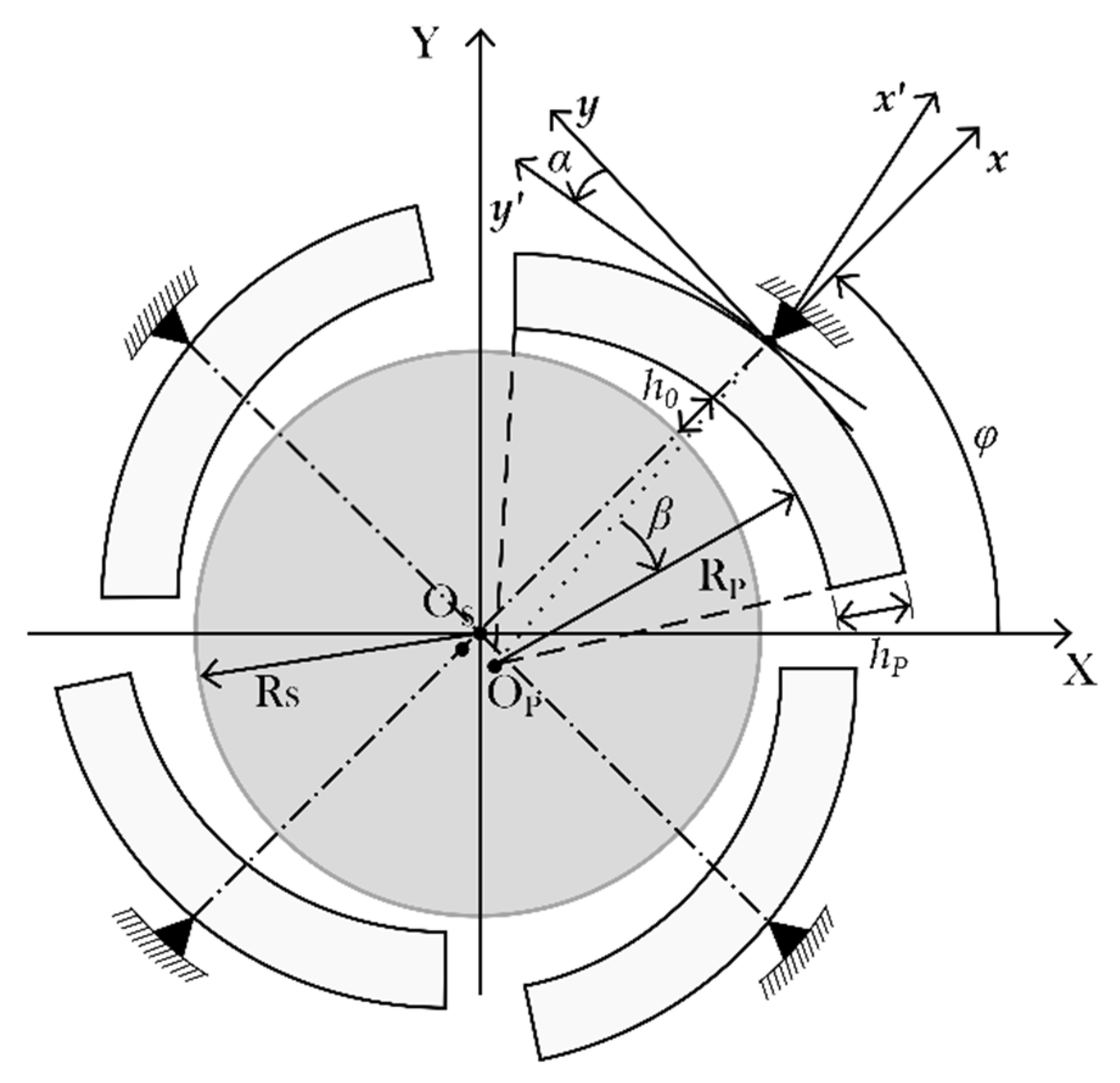
Figure 1 shows typical geometry of a tilting pad journal bearing with four pads mounted under load-between-pad (LBP) configuration, where
β is the angular position on the pad,
RP is the radius of the pad,
RS is the radius of the shaft,
OP is the center of the pad,
OS is the center of the shaft,
hP is the thickness of the pad,
h0 is the radial clearance, and
α is the angular displacement of the pad.
After the sequences of steps cited above, the equivalent coefficients are finally obtained using the perturbation method [
1,
2,
16], which consists of applying small perturbations to the shaft displacements and velocities around its equilibrium position, including the angular displacements and angular velocities of the bearing pads as well. Considering laminar flow bearings with small clearance ratios and reduced Reynolds number, the mass terms due to the fluid are neglected. Therefore, it yields nine stiffness and nine damping coefficients for each pad of the bearing concerning the local referential system (x’,y’).
Once the equation of motion of the j-th pad is transformed to the global coordinates (X,Y), the fundamental equation of motion for a tilting pad bearing rigid rotor system is given by Equation (1) [
17].
Equation (1) describes the equivalent coefficients of stiffness and damping related to the
x–
y directions. The full equation given above is not generally used for analysis purposes in rotor dynamics. Instead, it is reduced so that only the coordinates
x and
y associated with the translation motion of the journal are considered (rotor lateral vibration). For a review on reduction procedures, refer to the work of Dimond et al. [
17]. When the dynamic reduction is performed, the reduced model of bearing dynamics then becomes:
where
ms is the shaft mass;
cij is the reduced damping coefficient, and
kij is the reduced stiffness coefficient of the oil film (
i,
j =
x,
y);
fX and
fY are the excitation forces applied in two perpendicular directions. In transforming these equations into frequency domain and rearranging the terms, then, we have [
18]:
Equation (3) can also be written in matrix notation as
in which
S(ω) represents the mechanical impedance matrix, whose terms are complex numbers that represent the equivalent coefficients of stiffness and damping of the bearing. The model described by Equation (4) is widely adopted for the experimental identification of equivalent dynamic coefficients. Considering the test rig design proposed in this paper, to estimate the impedance matrix of the oil film, this requires the signals of excitation forces and dynamic responses in two perpendicular directions. In the first place, one excites the shaft in a direction (direction 1) and measures the excitation signal together with the response signals of the shaft in that direction and its perpendicular direction (direction 2). A similar process must be carried out in direction 2. After measuring the two excitation signals and the four response signals in the time domain, they are then transformed into the frequency domain. Subsequently, the signals are used as input into a calculation program so that four mechanical impedances of the linearized system are calculated.
Thus, the matrix of the equivalent coefficients of stiffness and damping are estimated as:
However, as expected, model verification and validation are crucial before practical applications. For this purpose, a test rig specifically conceived for bearings testing is presented and discussed here.
3. Test Rig Design Description
The concept of a dedicated test rig for bearings model validation must account for basic information such as force and displacement measurements in the bearing plane (
Figure 1), lubricant temperature, and rotation speed, in addition to other control and assembly parameters. These features are mandatory to obtain good compliance between theoretical model and physical effects in full hydrodynamic lubricated bearings.
Figure 2 shows an outline of the proposed test rig indicating the main components. The CAD (Computer-Aided Design) model and the complete dynamic analysis of the test bench draft were accomplished using the commercial Creo Parametric software. Differently from the most common test rig configuration in which the housing of the test bearing is free to move at the mid-span of a fixed rotor supported by two generic bearings, here, the rotor is free to move as in a real configuration and two identical magnetic actuators support the shaft. In addition to providing support to the rotor, the magnetic actuators are also able to provide the excitation forces compatible with the testing demands.
Based on the requirements for validating the tilting pad bearing models approached here, some operational parameters have to be defined. Under this perspective, the proposed configuration enables tests on TPJBs with diameters of 30 mm, with length–diameter ratios of L/D = 0.6—this research refers to a commercial tilting pad bearing for certain industrial applications, such as compressors and turbines. The bearing of reduced size was chosen to facilitate the execution of the experimental tests in a laboratory environment, where there are limitations of physical spaces and equipment for loading force applications—maximum load of about 1.5 kN and rotation speed range from 0 to 3000 rpm. The shaft is connected by flexible coupling (component 2 in
Figure 2) to a 3.7 kW three-phase asynchronous drive motor, which is controlled by a frequency inverter. The motor support is equipped with a compound slide table that provides rapid and accurate alignment positioning, providing vertical plane motion with fine adjustment of 0.05 mm in both reference axes.
3.1. Magnetic Actuators
According to the numerical analyses of the bearing models to be tested, the design of the magnetic actuators was developed to meet the load requirements on the bearings, as previously mentioned. Taking into account the influence of the most significant design parameters on the electromagnetic excitation force, such as electric current, excitation frequency, and air gap [
19], the project of the magnetic actuators is based on the best design parameter combinations. Besides these relevant parameters, another important design feature is the surface of the actuator poles that can present a flat (
Figure 3a) or a round shape (
Figure 3b).
Regarding the surface of the actuator poles, the study carried out by Furtado et al. [
20,
21] showed that a flat pole surface can be adapted to various shaft diameters, but it leads to difficulties in the force evaluation because of the non-constant air gap. Otherwise, considering a round pole surface, the pole shape has to be defined to each shaft diameter. Despite that, a round surface has the advantage that the air gap is constant in the cross-section. Therefore, the flux density distribution across the air gap using a round pole is practically constant, which is easier to handle for the force evaluation. In this project, the magnetic flux density was directly measured with Hall sensors in the surface of the actuator poles, which results in the force estimations being even better than using the current air gap method. From these analyses, the magnetic actuators were projected to have homopolar geometry, since this geometry presents fewer energy losses, as pointed out by Allaire et al. [
22]. Unlike the magnetic actuator project in references [
19,
20,
21], the current design presents some improvements. The primary upgrade was to design an actuator able to supply excitation at two orthogonal directions. Regarding reference [
23], the current frame is divided into two parts, which allows easy assembly. It has geometric characteristics that keep rigid joints, contributing to a good alignment of the components. Screws are used for fixing and aligning at the same time. Further, the cover at the back of the magnetic actuator houses a backup bearing (made of self–lubricating material) to protect the system when magnetic bearings fail. Moreover, the current system also allows shaft levitation and position control inside the bearing.
As noted in the literature [
19,
20,
21,
23], magnetic actuators can only generate attraction forces. Hence, to overcome this physical property and enable the excitation of a rotating shaft in two opposite directions, two opposite pairs of poles are needed. The model of this configuration is known as differential assembly. Therefore, the actuator configuration contains two pairs of differential mountings arranged at 45° and −45° to the inertial reference framework, so each actuator is able to excite the rotor in perpendicular directions, as shown in
Figure 4. The maximum load corresponds to a maximum air gap of 1.6 mm. There are eight coils, each of them with 420 cooper wire turns, totaling 840 turns for each of the four ferromagnetic cores. Another constructive parameter is the poles area of 35 × 26 mm
2.
To determine the natural frequencies of the magnetic actuator, its finite element model was created by using a mesh with a total of 17,983 tetrahedral elements and 4953 nodes. As boundary conditions, the four internal surfaces matching to the screw holes were constrained, being in accordance with those imposed in the actual assembly.
Figure 5 presents the first and second vibrational modes, corresponding to the frequencies of 540 Hz and 803 Hz. These frequencies are beyond the operating range, which is up to 50 Hz. Hence, it is expected that its dynamic behavior should not influence the dynamic response of the bearings within the expected frequency range to be tested. The concept of the shaft of the experimental test rig foresees parallelism to the magnetic actuator bore surface. From the restrictions imposed by the air gap of the magnetic bearings, a series of shafts with different diameters must provide several preload values of 0.3, 0.5, 0.7, and 0.9. In addition, the maximum feasible distance between the magnetic actuators is 820 mm.
3.2. Bearing Housing and Supporting Structure
The complete design of the bearing housing is intended to directly satisfy the geometric compatibility with the commercially manufactured TPJBs available for test purposes. This compatibility is related not only to the main dimensions of the bearings but also to the necessity of accessibility in the arrangements for the assembly of pressure and temperature sensors, accelerometers, as well as for the inlet and outlet of lubricating oil, properly indicated in
Figure 6. For the whole dimensioning, the outer diameter of 85.0 mm of the bearings was taken as reference. Two substructures (internal and external) then compose the bearing housing, both of them split into upper and lower half parts (
Figure 6 and
Figure 7). A frontal disc accommodates instrumentation cables, as well as the oil collector (
Figure 6 and
Figure 8).
According to
Figure 6, two holders attached to the external bearing housing and the external side of the frontal disc provide support for the inductive proximity sensors arranged 90° to each other. As shown in
Figure 7, the bearing housing upper half contains four internal holes to accommodate the anti-rotation pin that comes attached to the manufactured bearing. From this arrangement of holes, it is possible to perform experimental tests under load-on-pad (LOP) and load-between-pad (LBP) configurations in multilobe and tilting pad bearings. Further, two openings in the housing lower half allow access to the pressure sensor.
According to
Figure 8, a hollow cylindrical salience coupled to the internal side of the frontal disc guarantees the proper adjustment with the lateral surface of the bearing, limiting its lateral motion. In addition, four extra ledges avoid the contact between the cables of the temperature sensors and the rotating shaft.
As observed in
Figure 6,
Figure 7 and
Figure 8, the design details were developed to meet the instrumentation of the bearings. Moreover, it is versatile in the sense of being achievable to perform tests on rolling bearings, so it is equipped with split bushing (internal housing structure) to accommodate different bearing types. A frame connects the bearing housing to the steel base by two orthogonal load cells and a set of eight leaf springs (see
Figure 9) in order to decouple the
x–
y directions [
24].
Having attained the necessary design features for the bearing housing, a finite element model with a total of 24,631 tetrahedral elements and 7033 nodes was created to determine its natural frequencies. To reproduce the real boundary conditions, it was assumed the ones indicated in
Figure 10a.
Figure 10b,c display the first two vibrational modes corresponding to the frequencies of 44 Hz and 171 Hz. One notes the first frequency is close to the upper limit of the bench operating range (0–50 Hz). However, it is expected that this result does not compromise the bearing housing design since this mode has a small influence on the rotor lateral dynamics response. Even if there is some amplitude peak in the system response at that frequency, it can be identified that it refers to the natural frequency of the bearing housing.
Similarly, the base plate of the supporting structure is designed long and wide enough (20 × 500 × 1200) to enable assemblies with different shaft lengths/diameters, in order to contemplate preload variation in tilting pad and multilobe bearings. In this case, the magnetic actuators can be mounted in different axial positions along the base to achieve further versatility. For instance,
Figure 11 illustrates two likely assembly positions (I and II), both having the bearing housing at the rotor mid-span.
To check the natural frequencies and the vibrational modes of the plate, the ten internal surfaces corresponding to the pedestal holes are supposed as constrained. In this case, a total of 7348 solid elements and 2838 nodes were created.
Figure 12 shows the first and second vibrational modes of the supporting plate at the frequencies of 360 Hz and 386 Hz. Thus, these frequencies are also beyond the operating range.
Furthermore, the entire support structure consists of a steel base plate connected by ten cylindric tubular pedestals to an inertial concrete structure, particularly designed to guarantee rigid foundation characteristics in the operational frequency range of the test bench. To check the hypothesis of rigid shaft for the frequency range of tests (0–50 Hz) and considering the boundary conditions for the shaft—supported and excited by two magnetic actuators—a dynamic behavior is expected between the free–free and constrained conditions. Thus, two modal analyses were performed. The first one was set free–free at the location of the magnetic actuator journals, while in the second one, the constrained condition was assumed. A total of 4153 solid elements and 1208 nodes were defined for both simulations.
Figure 13 shows the results for a shaft with a 29.94 mm diameter (corresponding to the preload of 0.5), total length of 1 m, and maximum span between actuators of 820 mm.
4. A Description of the Required Instrumentation and Test Rig Operation
In the previous section, the test bench design was described, highlighting the main features of the project of its components. Additionally, this section presents the instrumentation involved in the project and illustrates its integration within the operation flowchart to make the complete working of the test rig and the attainment of the desired measurements clear. Mounted on the test bearing housing are four (two per cross-section) inductive proximity sensors and three uniaxial acceleration sensors. The proximity sensors enable the measurement, in two orthogonal directions, of the relative displacements (x–y) between the bearing case and the rotor. By means of these probes, one can obtain the eccentricity ratio and dynamic orbital motions. The accelerometers measure the bearing housing acceleration; that is, they provide the indirect measurement of the inertia force. The load exerted on the housing is measured through two perpendicular load sensors with load ranges from 20 to 1000 kg (see
Figure 9).
Likewise, each magnetic actuator is equipped with two inductive proximity sensors also arranged perpendicularly to each other. To obtain the magnetic flux density and, consequently, the magnetic force, four Hall sensors are used (one per pole). As pointed out in [
23], the Hall sensor positioning may affect the calculation of the magnetic force if the magnetic field is not constant within the air gap. To achieve a very effective estimative of the magnetic force applied by the actuators, the authors suggest positioning the sensor in the central region of the actuator pole. Therefore, this project considers the Hall sensors mounted in the central region of each pole, since this location can reduce the magnetic field measurement error (and the corresponding magnetic force estimation) to 2%, and, if using one Hall sensor in each pole of the actuator, it can be reduced to only 1%.
Figure 14 indicates the probe locations in the bearing housing and the magnetic actuator.
As the manufactured TPJBs have five pads, five temperature sensors PT100 are available to measure the temperature in the bearing pads, with a maximum deviation of 0.8 °C compared to the set value in the range 0–100 °C. The PT100 sensor is located at 75 percent of the total pad arc length from the leading edge, as recommended by [
25]. Two thermocouples (type J) with a maximum deviation of 2.2 °C compared to the set value in the range 0–100 °C are used. One of them—positioned in the oil tank—determines the bearing housing inlet temperature. The second one—positioned in the oil collector, as illustrated in yellow in
Figure 14—determines the bearing housing outlet temperature. The data from the PT100 and thermocouples sensors can be used for assessing THD models to be validated. Since the bench also enables tests on fixed-geometry hydrodynamic bearings, it is equipped with a high-frequency pressure sensor, only employed in tests on multilobe bearings (fixed geometry). The pressure sensor (model 105C12) allows measurements within the range 0–6.895 MPa, with resolution of 0.14 kPa and maximum pressure value of 13.79 kPa. It is radially positioned within the multilobe bearing at the midplane along the axial and circumferential directions of the lobe, as highlighted in
Figure 15.
The eight inductive proximity sensors (model BI1.5–EG08–LU) with ranges of measurement from 0.25 to 0.125 mm perform with their respective signal conditioners, and all of their signals pass through a DC offset and anti-aliasing filters before being acquired. A conditioner is also used together with an accelerometer and pressure sensors. In addition, PT100 temperature sensors have their own dedicated acquisition module for them. As mentioned, the test rig has a triphasic motor and a frequency inverter, providing accurate and flexible control of the motor speed. The communication between the computer and the frequency inverter is made through a serial communication module.
A PWM amplifier is used to amplify the signal from the controllers toward the magnetic actuators. Of utmost importance is the control and data acquisition system Dspace MicroLaBox. This is a high-performance and versatile system that allows one to set up test conditions and to acquire the signals of the several probes installed on the test rig along with its auxiliary systems. The displacement signals from the proximity sensors and the force applied by the magnetic actuators, after being properly processed, are transformed into the frequency domain. In turn, these are input data (into Equation (4), for instance) for the identification process of the equivalent dynamic coefficients.
Figure 16 depicts the operating flowchart of the bench.
Finally, the lubrication system consists of a highly robust hydraulic pump made of four heads with independent adjustments, with an oil flow rate within the range from 0 to 300 L/h per head, which can be controlled mechanically or automatically. The feeding pressure is set by the pump pressure. A pressure gauge compatible with the range of measurement of the pump is used for measuring the feeding pressure. The gauge is immediately attached to the oil supply line at the bearing housing inlet. It is also equipped with a store tank positioned below the test rig. The oil is sent into the bearing housing through an appropriate hose that is connected to its upper part, where a hole allows the oil to reach the inside (see
Figure 6). The oil collectors attached to the bearing housing recover the outlet oil. Before the outlet oil returns to the tank, it passes through a filter to circulate again.
Based on the instrumentation available on the test bench, different validations can be performed in order to evaluate hydrodynamic and rolling-element bearings. For example, the pressure and temperature in the oil film of the bearing can be validated from measurements obtained by sensors installed in the bearing. Moreover, these validations can be performed under different operating conditions, in which the frequency inverter controls the rotor speed, and the magnetic actuators control the load on the test bearing.
It is important to highlight that the magnetic bearings used on this test bench allow the evaluation of the rotor’s dynamic responses in specific positions inside the test bearing, applying small force disturbances on the rotating shaft. Thus, the stiffness and damping coefficients of the oil film can be estimated based on the relationship between the disturbances of applied forces and the resulting variations of the rotor responses measured by sensors in the bearing housing. Finally, it is noted that these different tests and analyses show that the bench designed in this work is capable of working in different scenarios and applications used in rotating machines, highlighting its applicability and relevance for research in the rotor dynamics field.


