Article

A Triboelectric Nanogenerator for Energy Harvesting from Transformers’ Vibrations †

by
Agnes Nascimento Simões
1,
Danilo José Carvalho
1,
Eugênio de Souza Morita
1,
Haroldo Luiz Moretti
2,
Helen Velozo Vendrameto
3,
Li Fu
4,
Floriano Torres
5,
André Nunes de Souza
2,
Waldir Antonio Bizzo
1,* and
Talita Mazon
6,*
1
School of Mechanical Engineering, UNICAMP—University of Campinas, Campinas 13083-970, Brazil
2
Department of Electrical Engineering, UNESP—Universidade Estadual Paulista, São Paulo 14801-902, Brazil
3
Gestão de Ativos, CPFL Paulista, Campinas 13087-397, Brazil
4
Engenharia, CPFL Energia, Campinas 13087-397, Brazil
5
HOG, CPFL Geração, Campinas 13087-397, Brazil
6
Divisão de Micro e NanoMateriais, Centro de Tecnologia da Informação Renato Archer, Campinas 13069-901, Brazil
*
Authors to whom correspondence should be addressed.
This paper is an extended version of our paper published in 14th IEEE International Conference on Industry Applications (INDUSCON), São Paulo, Brazil, 15–18 August 2021.
Machines 2022, 10(3), 215; https://doi.org/10.3390/machines10030215
Submission received: 9 February 2022 / Revised: 28 February 2022 / Accepted: 8 March 2022 / Published: 18 March 2022
(This article belongs to the Section Electromechanical Energy Conversion Systems)

Abstract

:
Transformers can produce gases dissolved in oil that can cause damage to their structures, and preventing failures caused by these gases is a goal to be reached. There is a demand for wireless sensors to monitor those gases. Alongside its development, there is a growing interest in new energy sources enabling these technologies. Triboelectric nanogenerators can gather energy from the environment, such as mechanical energy from vibrations, and convert it into electricity from the contact of two dielectric materials. In this work, the authors propose the study of a low-cost and straightforward triboelectric nanogenerator (TENG) based on ZnO nanorods as a positive dielectric material, with PDMS:GO composites at different concentrations as the negative dielectric material. All the studies were carried out in a wide frequency range varying from 45 to 250 Hz. Additionally, an analysis of the addition of a steel spring into the TENG to improve the device’s generating output is shown. A power density of 246 mV m 2 and 4 V of the output voltage was obtained using a PDMS:GO 4% (w/w) composite and a steel spring. A correlation between the “mass-spring” system and the better performance of the triboelectric device is presented. Further, vibration frequencies in several external points of the transformer walls and the device’s performance in these frequencies are shown, and the results gathered from this data are discussed.

1. Introduction

Currently, there is a growing demand for monitoring gases dissolved in transformer oil, including hydrogen, hydrocarbons, and carbon oxides, to realize the diagnostic of failures and predict the life of a transformer [1,2,3]. The dissolved gas analysis (DGA) commercial devices currently use cables to power the sensors contained therein. However, the advent of the Internet of Things (IoT) and the possibility of using wireless sensors to monitor dissolved gases in transformer oil have brought challenges in developing new sources of energy [4,5].
Nanogenerators are considered promising to power sensor devices once they can convert the energy available in their surroundings, such as mechanical energy from vibrations, into electricity [6]. The mechanical energy of an environment can be transformed into electrical power using the piezoelectric or triboelectric effect [7,8,9,10]. Because of this, the use of nanogenerators for energy harvesting is an innovative, renewable, sustainable, and low-cost solution studied as an alternative for feeding wireless gas sensors [11,12,13]. Among the nanogenerators, triboelectric nanogenerators (TENGs) have been considered up-and-coming mechanical energy harvesters due to their high throughput via a simple operation [14,15,16].
TENGs generate electric power by collecting electrostatic kinetic energy induced in the contact electrification and electrostatic induction coupling [17]. The TENG’s physical principle with the contact-separation mode consists of the physical contact of two dielectric materials of the opposite ends of the triboelectric series [18]. When the two dielectric materials touch, opposite charges are generated on their surfaces. As such, a current will move from one electrode to another to achieve the electrostatic equilibrium during their contact and separation. Usually, vibration movement, such as that present in the walls of the transformer, can promote the contact and separation of the materials [19]. The output performance of TENGs is influenced by several factors, such as contact materials, system structures, and the contact surface’s morphology [20,21,22]. Because of this, most published papers focus on using different materials or expensive techniques, such as lithography, ion plasma, and etching, to increase the effective contact surface. However, the influence of the addition of a steel spring to a triboelectric nanogenerator (TENG) on the performance of its output power is less discussed. Recently, we reported the possibility of applying nanogenerators for energy harvesting in transformers. Still, using a steel spring to ensure the high electrical performance of the TENG was little discussed [23]. Among the various materials used in TENGs, zinc oxide (ZnO) nanostructures are promising due to their semiconductor properties, low cost, and ease of synthesis [18,24]. ZnO nanorods (ZnO NRs) are resistant, sensitive to small mechanical vibrations [25], biocompatible [26], show low toxicity, long-term stability [27], and fast electron transport [28]. In TENGs, ZnO nanostructures show positive polarity, since their characteristics tend to make them donate electrons.
On the other hand, polymers have been considered for use as an opposed pair to materials with positive polarity. Polymers tend to receive electrons, which have negative polarity [29]. Polydimethylsiloxane (PDMS) (Sylgard®184) is a low-toxicity polymer, biocompatible [30], easily moldable, and cured at low temperatures. Due to its high electron affinity, PDMS can work as an excellent negatively charged dielectric material [29] in ZnO nanostructures-based TENGs. Furthermore, graphene oxide (GO) can be incorporated into PDMS to improve the generation and collection of loads in TENGs.
GO is a 2D-structure material with oxygen groups on its surface that aid faster electron transport [31]. Apart from the numerous advantages of TENGs, there is a premise that increasing the surface area [32], the charge density of the surface [33,34], adding two-dimensional materials to store charge [35], or modifying the structural design of mechanical metal springs [36] can improve their performance. These characteristics are essential and influence contact time, approach and detachment speed, and the gap between the two electrodes.
In this work, the authors propose to study the use of a steel spring in ZnO (NRs)-based TENG design and its influence on energy harvesting from the transformers’ vibrations. The TENG was built using ZnO NRs as positive materials and PDMS:GO composites as negative materials. Different concentrations of the GO were tested, and the study was carried out in a wide frequency range (45 to 250 Hz). The authors also discuss the TENG’s ability to collect vibration energy from the wall of transformers and convert it into electrical energy, based on using a steel spring in the design of the device, and the natural vibration frequency.

2. Materials and Methods

2.1. Synthesis of ZnO NRs

Zinc oxide NRs were grown onto flexible copper tape (6 × 6 mm) by the chemical bath deposition method (CBD) at low temperatures. The synthesis was performed using ammonium hydroxide ( N H 4 O H ) and zinc nitrate hexahydrate ( Z n ( N O 3 ) 2 · 6 H 2 O ) as precursor agents. After synthesis, the ZnO NRs were characterized using scanning electron microscopy ((SEM) Tescan model Mira 3 XMU) and X-ray diffraction ((XRD) Shimadzu XRD 7000 X-ray diffractometer).

2.2. Preparation of the PDMS:GO Composite

PDMS film (10 × 10 mm) was obtained from a Sylgard®184 reagent (Dow Corning, Midland, MI, USA) using a 1:10 ratio. Aiming to prepare the PDMS:GO composite, the Sylgard®184 reagent was mixed with an appropriate amount of GO suspension (2 and 4% weight) using an ultrasound. GO suspension was prepared in our laboratory accordingly as previously reported in reference [37]. So, PDMS and PDMS:GO mixtures were deposited onto alumina substrate ( A l 2 O 3 ) by spin coating at 3000 rpm for 30 s. The films were then cured at 80 °C in a vacuum oven and characterized by optical microscopy (Olympus BX51) and scanning electron microscopy ((SEM) Tescan model Mira 3 XMU).

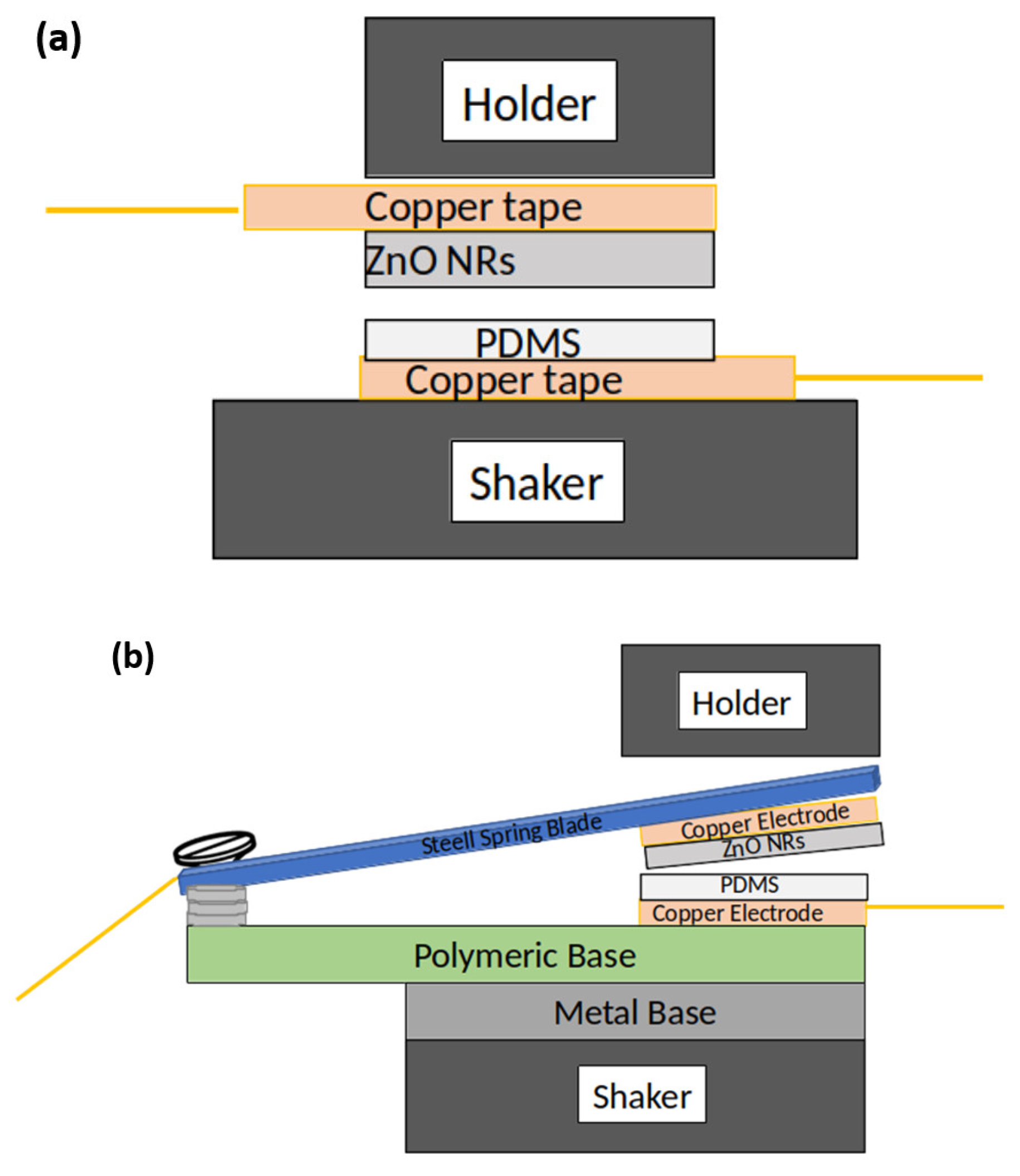
2.3. Assembly of Triboelectric Nanogenerators (TENGs)

TENGs were assembled to operate in a vertical contact-separation mode, according to Figure 1. Cu tape was used as conductive electrodes. ZnO NRs and PDMS or PDMS:GO films were utilized as triboelectric pairs. ZnO NRs grown on copper tape will act as the electron-donating material, PDMS film or PDMS:GO composite deposited on a copper tape will be the electron-receiving material. Figure 1 shows the two vertical configurations of TENGs built in this work. In all designs, PDMS/Cu tape was fixed in a shaker. In the first, the ZnO NRs/Cu tape was set in mechanical support, Figure 1a. In the second configuration, a steel spring blade (0.1 × 9.5 × 35 mm) was attached to the back of the ZnO NRs/Cu tape, and the set was positioned near the mechanical support, Figure 1b. The steel spring used for this purpose was analyzed by energy-dispersive X-ray analysis (EDX) by scanning electron microscopy ((SEM) Tescan model Mira 3 XMU) for elemental composition.

2.4. Electrical Characterization of the TENGs

Electrical characterization was performed in a system built in our lab to produce vibration on the device and collect the generated energy. The vibration was created from a generator (“shaker”) (DTC TEN-V20) coupled to an amplifier (DTC TEN-A100). In all experiments, the gain in the amplifier was kept at 1.5 V r m s to ensure the vibration amplitude was constant.
The voltage data generated by the device were collected from an oscilloscope (Tektronix TDS2014B). The nanogenerator was connected to an external circuit, Figure 1c. The buffer circuit acts as an impedance-matching circuit, allowing the correct voltage measurement over the characterization resistor without the impedance of the measuring instrument affecting the measurement. The voltage (Volts) is generated from the charge formation during the compression/removal process of both materials. From the result obtained (voltage) and the device’s active area, it is possible to obtain the power density value (mW m 2 ). The measurements were performed by varying the frequency range (45 to 250 Hz) at 10 M Ω . We also tested the devices at 45, 60, and 200 Hz in different resistance ranges (10 3 to 10 9   Ω ). To simulate maximum generated voltage in an open circuit ( V o c ) and the maximum current value when the generator leads are shorted ( I s c ), we utilize a resistor of 600 M Ω and a resistor of 1 k Ω in the external circuit, respectively.
To verify the capacity of the ZnO (NRs) and PDMS:GO 4 wt%-based TENG with steel spring addition (Figure 1b) to charge a 1000 µF capacitor, two experiments were realized. The first was theoretical and involved using the SPICE simulation software, Ltspice@, to simulate the voltage and time necessary to charge a 1000 µF capacitor of an analog device gas sensor. In the second, an external circuit was built in a protoboard containing a 1000 µF capacitor and a 1 M Ω resistor load, and connected to our TENG device. The amplifier was adjusted to input a fixed frequency of 60 Hz into the shaker, and the charged voltage was measured every 30 min using a digital multimeter connected to the capacitor.

2.5. Mechanical Characterization of the TENG

The TENG system can be characterized as a “mass-spring” system, representing a simple harmonic oscillator, where the forces indicated in Figure 2 act. F m is the force caused by the acceleration of the mass, F t is the spring force, and m is the mass of the blade. Both forces depend on the position of the spring end (x). The system was designed to act from the transformer wall vibration, and the movement is in the horizontal plane, orthogonal to the gravity acceleration. Therefore, there is no influence of the force on the gravity acceleration. For a flat blade, which is the case for the TENG tested here, the natural frequency ( f r ) of the system is calculated by Equation (1):
f r = 1 2 π 3 E I L 3 m
where E is the modulus of elasticity of the steel used (200 GPa), I is the moment of inertia of the blade cross-section, L is the length of the blade, and m is the mass of the blade. The dimensions and mass of the blade are in Table 1, resulting in a natural frequency of the order of 33 Hz.

2.6. Measurements of the Vibrations in Transformers

Vibration measurements of the external walls of transformers were made with a Fluke 805 m, which provides V r m s (root-mean-square velocity) and A (peak-to-peak displacement). Results of the vibration frequency at the measurement points were obtained from the integration of the velocity equation in the simple harmonic movement (SHM). The velocity (v) in the SHM, is given by (2):
v ( t ) = A ω sin ω t + π 2
where ω is the angular frequency and t is time. The root-mean-square velocity is defined by solving the function integrated into the range from 0 to T, given by (3).
V r m s 2 = 1 T 0 T v 2 d t = 1 T 0 T A ω sin ω t + π 2 2 d t
The development of the function can be seen, with T being the period of oscillation and ω the angular frequency of the movement, and the vibration frequency can be obtained using the values of V r m s and A provided by the measuring device from the resulting (4).
ω = 2 V r m s 2 A 2
where the relationship between the angular frequency ω and the period T is given by (5).
ω = 2 π T = 2 π f
The measurements were carried out in transformers with different powers (5, 25, 41, and 133 MVA). Figure 3 shows a picture of the vibration measurement at one of the measured positions.

3. Results and Discussion

3.1. Zno NRs onto the Copper Tape: Electron-Donating Material Characterization

Zinc oxide NRs were grown onto 6 × 6 mm flexible copper tape using the chemical bath deposition method (CBD). Figure 4 shows the scanning electron microscopy (SEM) images and XRD spectra of ZnO NRs onto copper tape. We can note a homogeneous growth of ZnO NRs with a diameter and length around 70 nm and 2 µm, respectively, and a total covering of the active area. The advantage of this research is that ZnO NRs are grown directly on the tape substrate without needing any traditional pattern transfer procedure to prepare micro/nanostructures onto the Cu tape surface. The rough structure of the ZnO NRs surface could increase the triboelectric contact and improve TENG output performance similar to Ni/Cu non-woven polyester [38].
Analyzing the XRD plot (Figure 4b), we can observe the presence of peaks indexed to ZnO, according to JCPDS card no. 36-1451 [39]. We also note the presence of peaks indexed to metallic Cu, JCPDS card no. 89-2838 [40]. The ZnO NRs show a hexagonal phase with a preferential orientation (002) and narrow peaks, indicating the excellent crystallinity of the nanorods. The copper peaks are attributed to the Cu tape used as the substrate.

3.2. Pdms and PDMS:GO Films: Electron-Receiving Material Characterization

PDMS-pure and PDMS:GO films were characterized by optical microscopy and SEM (Figure 5). The microstructure of the pure PDMS film is different from that with the addition of GO. This is probably because the GO sheets interfere with the polymerization/curing mechanism of the PDMS, since the Sylgard reagent is bicomponent. Nevertheless, the PDMS:GO films show a homogeneous microstructure with well-dispersed GO sheets on the polymeric matrix (Figure 5b,e and Figure 5c,f).

3.3. Characteristics of the Razor Blade Used as Steel Spring

A razor blade with the dimensions of 0.1 × 9.5 × 35 mm attached to the ZnO NRs/Cu tape was used as a steel spring to build the nanogenerators. As the composition of the spring material can affect the natural frequency of the device, the steel spring was characterized by SEM and EDX analyses. An elemental analysis, Table 2, shows the presence of iron and chromium in its composition. The Fe:Cr wt% proportion is characteristic of a 400 series martensitic stainless steel used as a razor blade. Other elements present in the martensitic stainless steel, such as carbon, molybdenum, and vanadium, appear in small amounts and can not be detected by EDX analysis.

3.4. Teng Devices

Using ZnO NRs/Cu tape and PDMS:GO films/Cu tape should ensure the fabricated TENGs have an excellent cost-effective balance once the CBD and spin-coating techniques used to prepare the two triboelectric pairs are easy to handle, and the materials are low-cost. Besides, the steel spring and Cu tape make it easy to assemble. As such, it is interesting to analyze the performance of these TENG devices. In this work, the performance of the devices was evaluated in the typical vertical contact-separation mode.
The power density versus frequency obtained for all TENGs are shown in Figure 6. We can verify two influences on the built devices: the amount of GO added to the PDMS and the use of the steel spring. The influence of the latter in the generated power is less reported in the literature, and we will discuss it later. Regarding the amount of GO, the power density increases at higher concentrations. A double higher-density value around 60 Hz is obtained for the device prepared using PDMS 4 wt% GO (Figure 6a) without adding a steel spring to the TENG’s configuration. An increase in the power density is attributed to the oxygenated groups present on the surface of the GO, who assist in the load distribution process in the electron-receiving material contributing to improving the device’s performance. Another behavior observed in these devices is the broad peak of the power density in the function of the frequency (Figure 6).
The broad peak is more significant in devices prepared with the PDMS containing 0 or 2 wt% GO than with the 4 wt% GO. As GO is responsible for homogeneously distributing the load in the electron-receiving pair, its absence corroborates with the natural frequency of devices’ operations and is not so pronounced. The power density rises, and the peak of the power density becomes sharper around 60 Hz for all samples by adding a steel spring to the TENGs’ configurations (Figure 6b). It is essential to point out that the generation of electricity from our TENG comes from the transformation of mechanical work (vibration) due to the contact and deformation of the active surfaces of the two materials through passing an electric current. When a steel spring is used in a TENG, the device’s behavior is similar to “mass-spring” devices, allowing them to operate close to the natural frequency of the set. The movement amplitude is maximized in this condition, and forces act on the active surfaces. The results obtained indicate the importance of using a steel spring in the configuration of a TENG to improve the power density, making it operate as close to the natural frequency as possible.
Although the addition of 4 wt% GO provided a slightly higher power density in these devices, the addition of the spring steel had a more significant influence on the device’s performance. Recently, Wardhana et al. [41] reported that a high output voltage depends on the separation velocity between the triboelectric layers, not on the separation distance. Using a steel spring in the TENGs’ configuration could also control the separation velocity better.
Aiming to verify the influence of the addition of a steel spring in the performance of the devices in different vibration frequencies, the TENGs prepared using PDMS:4 wt% GO were characterized at 45, 60, and 200 Hz in the 10 3 to 10 9 Ω range. The results are shown in Figure 7.
The devices work better at 60 Hz for the two configurations than at other frequencies. This frequency is approximately a multiple of the natural frequency calculated by Equation (1): 32.8 Hz. Using a steel spring favors obtaining a device with better performance at 60 Hz or less, and a sharper peak. Table 3 shows the output values, varying resistance loads, and frequencies obtained from the different devices. Two different values for voltage, current, and power density are shown for the two assemblies of the devices. The first correspond to those obtained from the voltage reading of an oscilloscope connected to a TENG in a resistive output load. The second are the optimal values obtained for load resistance, voltage, and current determined by varying the values of the load resistance and achieving a maximum or near-maximum power peak to determine the optimal load resistance (Figure 8).
The best power density was obtained for the TENG assembled with a steel spring and working at 60 Hz. We found a power density around 246 mW m 2 at 8.2 MΩ from an oscilloscope reading in this condition. The optimal power density, voltage, and load were 155 mW m 2 , 5.1 V, and 4.5 M Ω , respectively. The difference between these values is related to the high impedance of the TENG, and it was observed for all assembled devices and characterized at different frequencies [42]. Another issue observed during the characterizations is the similarity of the power density values at 200 Hz for both assembled devices (without and with steel spring, Table 3). It is well known that the steel spring’s dimensions, kind of material, and weight influence the natural frequency of devices’ operations, and in-plane spring-kind devices. The characteristics of the metal spring used here, for example, thickness and weight, may not be appropriate for TENGs working at 200 Hz, and they need to be studied to improve the power density at this frequency.
Figure 8 shows the voltage, current, and power density results at the different frequencies (45, 60, and 200 Hz) for the TENG-based ZnO NRs and PDMS:GO 4% wt assembled with a steel spring blade. The output voltage is similar to devices working at 45 and 60 Hz, and around 4.69 and 5.1 V (Figure 8a,b, Table 3). However, the output current and the power density obtained at 60 Hz are almost two times greater than 45 Hz. By increasing the frequency to 200 Hz, the device’s performance decreases by half. As mentioned above, the characteristics of the metal spring, such as thickness and weight, need to be studied to improve the power density of the TENGs at frequencies higher than 60 Hz.
Figure 9 shows the open-circuit voltage ( V o c ) and closed-circuit current ( I s c ) outputs of the devices prepared using ZnO NRs and PDMS:GO 4 wt% with the addition or not of the steel spring in their assembly. V o c and I s c were obtained after the cyclic stretching and relaxing of the TENGs. The plots show that the V o c is similar for both devices, indicating a saturation, while I s c increases for the device assembled with a steel spring. The increase in the I s c is attributed to the rapid induction and charge transfer resulting from the maximization of the movement amplitude, which augments the contact region. Besides, the device assembled with a steel spring produces more output peaks than that without a steel spring. These findings corroborate the better output voltage and power density results obtained for the device assembled with the steel spring. The TENG containing the steel spring produces a maximum V o c of 12 V and a maximum I s c of 2.5 µA.
The Ltspice@ simulated the voltage and time necessary for a ZnO (NRs) and PDMS:GO 4 wt%-based TENG assembled with a steel spring addition to charge a 1000 µF capacitor in an analog circuit (Figure 10a). Through simulations performed, we verified to be possible to charge a 1000 µF capacitor from 0 V to 3.3 V in 3.4 h. However, when our TENG device was connected to an external circuit built in a protoboard containing a 1000 µF capacitor and a 1 M Ω resistor load, a voltage of 3.3 V was only reached after 5.3 h of uninterrupted operation, reaching 3.9 V after 7 h (Figure 10b). Considering the use of a single generator appropriately fixed in a transformer wall vibrating at 60 Hz, the TENG-based ZnO NRs and PDMS:GO 4% wt assembled with a steel spring blade could be able to feed the gas sensor circuit after 5 or 7 h of operation. However, more circuits could be combined to obtain greater capacity in the supply of the current or the voltage supplied to the load in a shorter time.
The working principle of a TENG is explained in Figure 11. Initially, the dielectric materials (ZnO NRs and PDMS) are apart from each other (a). In this position, both dielectric materials are electrostatic neutral. Applying an external vibration results in the approximation of the dielectrics and charges are generated by the electrical forces of attraction/repulsion [33], and the neutral equilibrium is broken. ZnO NRs and PDMS are materials located at opposite ends of the triboelectric series [18]. When in contact, the surface area of both materials is polarized with an opposite charge. The PDMS surface becomes mostly negative and works as an electron acceptor. The GO has an excellent charge distribution and a high surface area; its structure is composed of oxygen-functional groups.
All these properties enhance the PDMS-negative feature. Therefore, these regions act like electron traps, increasing the negative charge density in the PDMS:GO-film surface. ZnO NRs is a semiconductor, and it is classified as a positive triboelectric material, meaning it is going to donate electrons. When PDMS and ZnO NRs are repeatedly pressed against each other, the motion produces a potential difference that leads to a generation of charge and current. Once separated, a potential difference is induced by an electron flow between the two dielectric materials coming from the top electrode to the bottom electrode. This electron flow causes a current from the bottom electrode to the top electrode.

3.5. Calculated Frequency in the External Walls of the Transformers

Vibration measurements of the external walls of the transformers were made with a Fluke 805 Vibration Meter Tester, which provides V r m s (root-mean-square velocity) and A (peak-to-peak displacement). The calculated frequency results obtained in different points of the transformers from Fluke measurements are shown in Table 4. Apart from the main frequency of 60 Hz, we also found vibration frequencies ranging from 45 to 242 Hz. These other frequencies are probably the result of combining the main frequency harmonics and vibration attenuation through the various components of the set (structure, coils, and dielectric oil). Moreover, a considerable variation of the vibration frequency is observed in different transformer points. This variation can be higher when considering transformers of different powers. The results suggest that choosing the appropriate local to install a TENG in a transformer is also crucial to improving its performance. Considering that the frequency vibration of the transformers can be around 45–200 Hz, the TENGs constructed here can be a powerful device for converting mechanical energy into electricity to power wireless gas sensors in transformers.

4. Conclusions

A triboelectric nanogenerator was developed and tested for powering wireless sensors applied to power transformers. The results showed the importance of using a steel spring to assemble the devices based on ZnO (NRs) and PDMS:GO 4 wt% composites to improve their performance. The best results were obtained for the TENG built with a steel spring operating at 60 Hz. The optimal power density, voltage, and load were 155 mW m 2 , 5.1 V, and 4.5 M Ω at these conditions, respectively. Although the nanogenerator generates less voltage at 45 and 200 Hz, the device still operates. Besides, more circuits could be combined to obtain greater capacity in the supply of the current or the voltage. The characteristics of the TENG device built in this work enable its use in different locations at the transformer surface, and most of them showed vibration frequencies ranging from 45 to 242 Hz. This nanogenerator can be a powerful low-cost option for converting mechanical energy into electricity to power wireless gas sensors in transformers.

Author Contributions

Conceptualization, T.M., W.A.B. and A.N.d.S.; methodology, T.M., W.A.B., D.J.C. and A.N.S.; formal analysis, A.N.S. and D.J.C.; investigation, A.N.S., D.J.C., E.d.S.M. and H.L.M.; resources, L.F. and H.V.V.; data curation, E.d.S.M.; writing—original draft preparation, A.N.S., D.J.C. and F.T.; writing—review and editing, T.M. and W.A.B.; visualization, H.L.M. and A.N.S.; project administration, H.V.V.; funding acquisition, L.F. Supervision, A.N.d.S. All authors have read and agreed to the published version of the manuscript.

Funding

This research was funded by the CPFL group through the Research and Development project PD-00063-3067/2019 with resources from ANEEL’s R&D program, and by the CNPq-Conselho Nacional de Desenvolvimento Científico e Tecnológico and FAPESP-Fundação de Amparo à Pesquisa do Estado de São Paulo (CEPID-CDMF 2013/07296-2).

Institutional Review Board Statement

Not applicable.

Informed Consent Statement

Not applicable.

Data Availability Statement

Not applicable.

Acknowledgments

The authors would like to thank CTI-Nano, the strategic laboratory from SisNano and MCTI, and the laboratory of the microscopy—CNPEM, for their support of this research.

Conflicts of Interest

The authors declare no conflict of interest.

Abbreviations

The following abbreviations are used in this manuscript:
2Dtwo dimensional
CBDchemical bath deposition
EDXenergy dispersive X-ray analisys
GOgraphene oxide
IoTInternet of Things
JCPDSInternational Centre for Diffraction Data Sample
Preparation Methods in X-Ray Powder Diffraction
PDMSPolydimethylsiloxane
SEMscanning electron microscopy
SHMsimple harmonic movement
TENGtriboelectric nanogenerator
XRDX-ray diffraction
ZnO NRsZinc oxide nanorods

References

  1. Zhang, H.; Lu, Y.; Ghaffarinejad, A.; Basset, P. Progressive Contact-Separate Triboelectric Nanogenerator Based on Conductive Polyurethane Foam Regulated with a Bennet Doubler Conditioning Circuit. Nano Energy 2018, 51, 10–18. [Google Scholar] [CrossRef]
  2. Secor, E.B.; Lim, S.; Zhang, H.; Frisbie, C.D.; Francis, L.F.; Hersam, M.C. Gravure Printing of Graphene for Large-area Flexible Electronics. Adv. Mater. 2014, 26, 4533–4538. [Google Scholar] [CrossRef] [PubMed]
  3. Son, D.; Lee, J.; Qiao, S.; Ghaffari, R.; Kim, J.; Lee, J.E.; Song, C.; Kim, S.J.; Lee, D.J.; Jun, S.W.; et al. Multifunctional Wearable Devices for Diagnosis and Therapy of Movement Disorders. Nat. Nanotechnol. 2014, 9, 397–404. [Google Scholar] [CrossRef] [PubMed]
  4. Zhang, H.; Li, B.; Yuan, W.; Kraft, M.; Chang, H. An Acceleration Sensing Method Based on the Mode Localization of Weakly Coupled Resonators. J. Microelectromech. Syst. 2016, 25, 286–296. [Google Scholar] [CrossRef]
  5. Tao, K.; Tang, L.; Wu, J.; Lye, S.W.; Chang, H.; Miao, J. Investigation of Multimodal Electret-Based MEMS Energy Harvester with Impact-Induced Nonlinearity. J. Microelectromech. Syst. 2018, 27, 276–288. [Google Scholar] [CrossRef]
  6. Fan, F.R.; Tang, W.; Wang, Z.L. Flexible Nanogenerators for Energy Harvesting and Self-Powered Electronics. Adv. Mater. 2016, 28, 4283–4305. [Google Scholar] [CrossRef]
  7. Khazaee, M.; Rezaniakolaie, A.; Rosendahl, L. A Broadband Macro-Fiber-Composite Piezoelectric Energy Harvester for Higher Energy Conversion from Practical Wideband Vibrations. Nano Energy 2020, 76, 104978. [Google Scholar] [CrossRef]
  8. Cai, M.; Liao, W.H. Enhanced Electromagnetic Wrist-Worn Energy Harvester Using Repulsive Magnetic Spring. Mech. Syst. Signal Process. 2021, 150, 107251. [Google Scholar] [CrossRef]
  9. Qiao, G.; Wang, J.; Yu, X.; Jia, R.; Cheng, T.; Wang, Z.L. A Bidirectional Direct Current Triboelectric Nanogenerator with the Mechanical Rectifier. Nano Energy 2021, 79, 105408. [Google Scholar] [CrossRef]
  10. Zhao, C.; Yang, Y.; Upadrashta, D.; Zhao, L. Design, Modeling and Experimental Validation of a Low-Frequency Cantilever Triboelectric Energy Harvester. Energy 2021, 214, 118885. [Google Scholar] [CrossRef]
  11. Lee, J.; Kwon, H.; Seo, J.; Shin, S.; Koo, J.H.; Pang, C.; Son, S.; Kim, J.H.; Jang, Y.H.; Kim, D.E.; et al. Conductive Fiber-Based Ultrasensitive Textile Pressure Sensor for Wearable Electronics. Adv. Mater. 2015, 27, 2433–2439. [Google Scholar] [CrossRef] [PubMed]
  12. Cui, S.; Zheng, Y.; Zhang, T.; Wang, D.; Zhou, F.; Liu, W. Self-Powered Ammonia Nanosensor Based on the Integration of the Gas Sensor and Triboelectric Nanogenerator. Nano Energy 2018, 49, 31–39. [Google Scholar] [CrossRef]
  13. Cao, R.; Wang, J.; Zhao, S.; Yang, W.; Yuan, Z.; Yin, Y.; Du, X.; Li, N.W.; Zhang, X.; Li, X.; et al. Self-Powered Nanofiber-Based Screen-Print Triboelectric Sensors for Respiratory Monitoring. Nano Res. 2018, 11, 3771–3779. [Google Scholar] [CrossRef]
  14. Park, I.; Maeng, J.; Lim, D.; Shim, M.; Jeong, J.; Kim, C. A 4.5-to-16 μW Integrated Triboelectric Energy-Harvesting System Based on High-Voltage Dual-Input Buck Converter with MPPT and 70V Maximum Input Voltage. In Proceedings of the 2018 IEEE International Solid—State Circuits Conference—(ISSCC), San Francisco, CA, USA, 11–15 February 2018; pp. 146–148. [Google Scholar] [CrossRef]
  15. Hinchet, R.; Seung, W.; Kim, S.W. Recent Progress on Flexible Triboelectric Nanogenerators for SelfPowered Electronics. ChemSusChem 2015, 8, 2327–2344. [Google Scholar] [CrossRef]
  16. Wang, Z.L. Triboelectric Nanogenerators as New Energy Technology for Self-Powered Systems and as Active Mechanical and Chemical Sensors. ACS Nano 2013, 7, 9533–9557. [Google Scholar] [CrossRef] [PubMed]
  17. Basset, P.; Blokhina, E.; Galayko, D. Electrostatic Kinetic Energy Harvesting; John Wiley & Sons: Hoboken, NJ, USA, 2016. [Google Scholar]
  18. Costa, S.V.; Azana, N.T.; Shieh, P.; Mazon, T. Synthesis of ZnO Rod Arrays on Aluminum Recyclable Paper and Effect of the Rod Size on Power Density of Eco-Friendly Nanogenerators. Ceram. Int. 2018, 44, 12174–12179. [Google Scholar] [CrossRef]
  19. Dharmasena, R.D.I.G.; Jayawardena, K.D.G.I.; Mills, C.A.; Deane, J.H.B.; Anguita, J.V.; Dorey, R.A.; Silva, S.R.P. Triboelectric Nanogenerators: Providing a Fundamental Framework. Energy Environ. Sci. 2017, 10, 1801–1811. [Google Scholar] [CrossRef]
  20. Kim, D.W.; Lee, J.H.; Kim, J.K.; Jeong, U. Material Aspects of Triboelectric Energy Generation and Sensors. NPG Asia Mater. 2020, 12, 1–17. [Google Scholar] [CrossRef]
  21. Muthu, M.; Pandey, R.; Wang, X.; Chandrasekhar, A.; Palani, I.A.; Singh, V. Enhancement of Triboelectric Nanogenerator Output Performance by Laser 3D-Surface Pattern Method for Energy Harvesting Application. Nano Energy 2020, 78, 105205. [Google Scholar] [CrossRef]
  22. Yin, X.; Liu, D.; Zhou, L.; Li, X.; Zhang, C.; Cheng, P.; Guo, H.; Song, W.; Wang, J.; Wang, Z.L. Structure and Dimension Effects on the Performance of Layered Triboelectric Nanogenerators in Contact-Separation Mode. ACS Nano 2019, 13, 698–705. [Google Scholar] [CrossRef]
  23. Simões, A.N.; Carvalho, D.J.; de Souza Morita, E.; Vendrameto, H.V.; Fu, L.; Torres, F.; de Souza, A.N.; Bizzo, W.A.; Mazon, T. Application of Steel Spring on the ZnO Nanorods Self-Powered Triboelectric Nanogenerator for Efficient Energy Harvest in Transformers. In Proceedings of the 2021 14th IEEE International Conference on Industry Applications (INDUSCON), São Paulo, Brazil, 15–18 August 2021; pp. 904–909. [Google Scholar] [CrossRef]
  24. Zhou, W.; Zhang, X.; Zhao, D.; Gao, M.; Xie, S. ZnO Nanorods: Morphology Control, Optical Properties, and Nanodevice Applications. Sci. China Phys. Mech. Astron. 2013, 56, 2243–2265. [Google Scholar] [CrossRef]
  25. Cherumannil Karumuthil, S.; Rajeev, S.P.; Varghese, S. Piezo-Tribo Nanoenergy Harvester Using Hybrid Polydimethyl Siloxane Based Nanocomposite. Nano Energy 2017, 40, 487–494. [Google Scholar] [CrossRef]
  26. Ma, S.; Zhang, X.; Liao, Q.; Liu, H.; Huang, Y.; Song, Y.; Zhao, Y.; Zhang, Y. Enzymatic Lactic Acid Sensing by In-doped ZnO Nanowires Functionalized AlGaAs/GaAs High Electron Mobility Transistor. Sens. Actuators B Chem. 2015, 212, 41–46. [Google Scholar] [CrossRef]
  27. Anand, K.; Singh, O.; Singh, R.C. Different Strategies for the Synthesis of Graphene/ZnO Composite and Its Photocatalytic Properties. Appl. Phys. A 2014, 116, 1141–1148. [Google Scholar] [CrossRef]
  28. Kumar, B.; Kim, S.W. Energy Harvesting Based on Semiconducting Piezoelectric ZnO Nanostructures. Nano Energy 2012, 1, 342–355. [Google Scholar] [CrossRef]
  29. Diaz, A.F.; Felix-Navarro, R.M. A Semi-Quantitative Tribo-Electric Series for Polymeric Materials: The Influence of Chemical Structure and Properties. J. Electrost. 2004, 62, 277–290. [Google Scholar] [CrossRef]
  30. Hassani, F.A.; Lee, C. A Triboelectric Energy Harvester Using Low-Cost, Flexible, and Biocompatible Ethylene Vinyl Acetate (EVA). J. Microelectromech. Syst. 2015, 24, 1338–1345. [Google Scholar] [CrossRef]
  31. Lee, C.; Wei, X.; Kysar, J.W.; Hone, J. Measurement of the Elastic Properties and Intrinsic Strength of Monolayer Graphene. Science 2008, 321, 385–388. [Google Scholar] [CrossRef]
  32. Tcho, I.W.; Kim, W.G.; Jeon, S.B.; Park, S.J.; Lee, B.J.; Bae, H.K.; Kim, D.; Choi, Y.K. Surface Structural Analysis of a Friction Layer for a Triboelectric Nanogenerator. Nano Energy 2017, 42, 34–42. [Google Scholar] [CrossRef]
  33. Wang, S.; Xie, Y.; Niu, S.; Lin, L.; Liu, C.; Zhou, Y.S.; Wang, Z.L. Maximum Surface Charge Density for Triboelectric Nanogenerators Achieved by Ionized-Air Injection: Methodology and Theoretical Understanding. Adv. Mater. 2014, 26, 6720–6728. [Google Scholar] [CrossRef]
  34. Wang, J.; Wu, C.; Dai, Y.; Zhao, Z.; Wang, A.; Zhang, T.; Wang, Z.L. Achieving Ultrahigh Triboelectric Charge Density for Efficient Energy Harvesting. Nat. Commun. 2017, 8, 88. [Google Scholar] [CrossRef] [PubMed] [Green Version]
  35. Wu, C.; Kim, T.W.; Choi, H.Y. Reduced Graphene-Oxide Acting as Electron-Trapping Sites in the Friction Layer for Giant Triboelectric Enhancement. Nano Energy 2017, 32, 542–550. [Google Scholar] [CrossRef]
  36. Zhao, Z.; Liu, J.; Wang, Z.; Liu, Z.; Zhu, W.; Xia, H.; Yang, T.; He, F.; Wu, Y.; Fu, X.; et al. Ultrasensitive Triboelectric Nanogenerator for Weak Ambient Energy with Rational Unipolar Stacking Structure and Low-Loss Power Management. Nano Energy 2017, 41, 351–358. [Google Scholar] [CrossRef]
  37. Vessalli, B.A.; Zito, C.A.; Perfecto, T.M.; Volanti, D.P.; Mazon, T. ZnO Nanorods/Graphene Oxide Sheets Prepared by Chemical Bath Deposition for Volatile Organic Compounds Detection. J. Alloys Compd. 2017, 696, 996–1003. [Google Scholar] [CrossRef] [Green Version]
  38. Zargari, S.; Koozehkanani, Z.D.; Veladi, H.; Sobhi, J.; Rezania, A. Cost-Effective Fabrication Approaches for Improving Output Performance of Triboelectric Energy Harvesters. J. Electrost. 2022, 115, 103640. [Google Scholar] [CrossRef]
  39. Srivastava, V.; Gusain, D.; Sharma, Y.C. Synthesis, Characterization and Application of Zinc Oxide Nanoparticles (n-ZnO). Ceram. Int. 2013, 39, 9803–9808. [Google Scholar] [CrossRef]
  40. Ramyadevi, J.; Jeyasubramanian, K.; Marikani, A.; Rajakumar, G.; Rahuman, A.A. Synthesis and Antimicrobial Activity of Copper Nanoparticles. Mater. Lett. 2012, 71, 114–116. [Google Scholar] [CrossRef]
  41. Wardhana, E.M.; Mutsuda, H.; Tanaka, Y.; Nakashima, T.; Kanehira, T.; Taniguchi, N.; Maeda, S.; Yonezawa, T.; Yamauchi, M. Harvesting Contact-Separation-Compression Vibrations Using a Flexible and Compressible Triboelectric Generator. Sustain. Energy Technol. Assess. 2020, 42, 100869. [Google Scholar] [CrossRef]
  42. Jayasvasti, S.; Thainiramit, P.; Yingyong, P.; Isarakorn, D. Technique for Measuring Power across High Resistive Load of Triboelectric Energy Harvester. Micromachines 2021, 12, 766. [Google Scholar] [CrossRef]
Figure 1. Design of the TENGs built in this work: (a) PDMS has the role of a spring material; (b) device containing a steel spring; (c) external circuit connected to the triboelectric nanogenerator.
Machines 10 00215 g001aMachines 10 00215 g001b
Figure 2. Forces acting on a “mass-spring” system.
Machines 10 00215 g002
Figure 3. Pictures of the vibration measurement: (A) one of the measured positions; (B) different measured points.
Machines 10 00215 g003
Figure 4. (a) Images obtained by SEM of the ZnO NRs grown onto Cu tape; (b) XRD spectra of ZnO NRs synthesized onto flexible copper substrate.
Machines 10 00215 g004
Figure 5. Images obtained by optical microscopy (ac), and SEM (df) of the samples prepared. (a,d) PDMS; (b,e) PDMS: 2% weight GO; (c,f) PDMS: 4% weight GO.
Machines 10 00215 g005
Figure 6. Power density versus frequency for TENGs assembled with different configurations: (a) TENG without a steel spring material; (b) device containing a steel spring.
Machines 10 00215 g006
Figure 7. Power density versus resistance for TENGs assembled with different configurations: (a) TENG without a steel spring material; (b) device containing a steel spring.
Machines 10 00215 g007
Figure 8. Voltage, current, and power density versus resistance obtained from the triboelectric devices assembled by using ZnO NRs with a steel spring blade and PDMS:GO 4% weight: (a) 45 Hz; (b) 60 Hz; (c) 200 Hz.
Machines 10 00215 g008
Figure 9. Maximum voltage ( V o c ) and current ( I s c ) generated by a TENG device based on ZnO NRs and PDMS:GO 4% wt at different assembly conditions: (a,b) V o c for the device built with and without steel spring, respectively; (c,d) I s c for the device assembled with and without steel spring, respectively.
Machines 10 00215 g009
Figure 10. (a) Circuit for testing charging of a 1 µF capacitor; (b) voltage obtained as a function of charging time.
Machines 10 00215 g010
Figure 11. Schematic representation of the working principle of a TENG: (a) at the beginning, both dielectric materials are electrically neutral; (b) the proximity of the materials causes separation of the charges due to the electrical attraction/repulsion; (c) when the materials are in contact, it is observed that there is the polarization of charges; (d) when the materials are coming apart it is observed that there is a potential difference between the dielectrics; (e) when separated, both materials go back to the neutral electric state.
Machines 10 00215 g011
Table 1. Characteristics of the steel spring blade.
LenghtWidthThicknessMassMoment of InertiaNatural Frequency
(mm)(mm)(mm)(g)(kg m 2 )(Hz)
35.09.50.10.267.9 × 10 16 32.8
Table 2. Elemental analysis of the steel spring by EDX. Percentage of elements present in steel spring blade.
ElementAtomic No.NettoMass (%)Normalized Mass (%)Atom (%)Absolute Error (%)Relative Error (%)
Iron2698,97521.2684.7783.830.592.79
Chromium2424,0493.8215.2316.170.133.43
Table 3. Output values and varying resistance loads obtained from the device using PDMS:GO 4%, without steel spring, and with steel spring addition.
DeviceFrequencyLoadVoltageCurrentPower Density
(Hz)(MΩ)(V)(µA)(mW m 2 )
without steel45106.50.6592.8
spring60108.90.89176
(reading of an oscilloscope)2001050.554.9
without steel458.14.360.551.5
spring604.24.410.96101.7
(optimal value)2006.94.050.552.2
with steel45106.80.68124.3
spring608.28.61.05246.4
(reading of an oscilloscope)200609.50.1540.4
with steel458.14.690.663
spring604.55.11155.3
(optimal value)200132.870.1922.1
Table 4. Frequency calculation results from measuments obtained from transformers. Locations are indicated in Figure 3.
TransformerMeasurementAmplitudeSpeed VibrationVibration
CapacityLocation A pk (mm) V rms (mm s 1 )Frequency (Hz)
133 MVAfront side (a)0.0026052.38205
front side (b)0.0045054.87242
front side (c)0.0082454.68127
front side (d)0.005114.61202
radiator0.002521.47131
backside0.0038252.49146
5 MVAfront side0.0014750.3452
41 MVAfront side0.0045452.32115
front side0.0016550.6690
front side (j)0.0029851.35102
radiator0.001780.3545
25 MVAfront side0.0017550.85109
front side0.001290.3460
front side0.0011550.5199
radiator0.0016250.3954
Publisher’s Note: MDPI stays neutral with regard to jurisdictional claims in published maps and institutional affiliations.

