Abstract
The problem of the parametric design of ship hull structures is considered here. The parametric design of ship hull structures is intended to determine the dimensions of structural elements that meet the requirements of regulatory documents (Rules of Classification Societies/Strength Standards). It is shown that, in all existing shipbuilding CAD-CAM systems, the problems of the parametric design of ship hull structures are essentially not affected. A modern methodology for the parametric design of hull structures is proposed, which defines a set of principles for the structural and logical organization of the design process, methods, and technical means for implementing design procedures. The most characteristic methodological principles of the parametric design of ship hull structures and other offshore engineering structures are identified: A systematic approach; modeling as one of the main methods for solving design problems; and a rational design strategy based on iterative search procedures that implement the methodological principle of successive complication of models and procedures for designing structures. The article considers the architecture and methodological foundations of the system for automated parametric design of ship hull structures (CADS-Hull), developed at the Saint Petersburg State Marine Technical University, Russia. The system is intended for use in design bureaus when designing civil ship hull structures on the basis of regulatory requirements of the Russian Maritime Register of Shipping and IACS General Rules in terms of large-capacity tankers, bulk carriers, and container ships.
1. Introduction
Ship hull structure design is a process of forming a geometric, structural, parametric, and structural-and-technological description of the structure and developing the technical documentation (on this basis) necessary for structure manufacturing in the conditions of ship hull production. Often, structural design is understood as the development of a hull structure using the universal software of modern computer graphic systems such as AutoCAD [1] and COMPAS-3D [2] or the corresponding blocks of “heavy” CAD/CAM systems (FORAN [3], AVEVA [4], etc.). Actually, the mentioned systems mainly provide the implementation of computer-aided construction processes. At the same time, the computer screen performs the function of an “electronic drawing board”, since mainly routine graphic procedures are automated in such graphic systems. Computer-aided construction can be implemented only if there is information about structure shape parameters and its elements’ dimensions. In this regard, ship hull structure design can be represented as a combination of two interlinked processes—computer-aided construction and parametric design. Computer-aided construction is intended for the formation of visual parameterized information regarding the structural composition of hull structures, as well as its geometric and construction concepts. One of the computer-aided design tasks is the development of structural drawings using modern office equipment. Parametric computer-aided design is intended to determine the dimensions of structural elements that meet the regulatory requirements (Rules of Classification Societies/Structures strength standards).
The problem with the parametric design of ship hull structures is hardly affected in existing shipbuilding CAD-CAM systems. To an extent, for the parametric design of ship hull structures, one can use (during verification calculations) Classification Societies’ computer-aided systems: MARS 2000 [5], VeriStar [6]—BV; NauticusHull [7], Poseidon [8]—DnV-GL; SafeHull, CSR Prescriptive Analysis software [9]—ABS; ATLAS [10]—Russian Maritime Register of Shipping (RMRS), and others, intended to check the compliance of the ship’s hull with the requirements of the Rules of Classification Societies. Parametric design automation requires specialized software. It is a very common notion that structural design comprises the structure’s calculations using software that implements the finite element method (FEM). It is known that, in order to perform finite element analysis, it is also necessary to obtain complete (even detailed) information about the structure, which does not exist or is not sufficient at the initial stages of designing.
Some basic information on the parametric settings of the hull shape and internal structures is given in the works of A. Papanikolau [11,12]. The basic principles of modeling ship structures based on an object-oriented approach, which is very relevant in terms of software development, are given in [13]. Ship structures are physical objects with a complex hierarchical structure, which is very well-suited to creating an information structure and methods for its processing in computer systems, which are programmed using an object-oriented approach.
A large amount of information on the modeling of ship structures is contained in works that reveal the problem of automating data preparation for FEM analysis (for example, in [14,15]). The preparation of such data is usually carried out separately from the parametric design of structures, but the system described in this article has special data translators for transferring the model to FEM analysis systems. The approach proposed in [14,15] was partially used to develop these translators in terms of describing plate and beam elements. The creation of structural models at the early stages of design, which are later used for FEM analysis and production preparation, are given in [16].
Historically, the computer modeling of ship structures originates from the preparation of documentation and drawings for the construction of a ship and the planning of the production process. A modern approach to the formation of this kind of information on the ship’s hull is shown in [17]. An example of the implementation of search optimization methods for the design of ship structures to minimize their mass can be found in a number of works [18,19,20].
A large set of studies, related to the development of the methodology, algorithms, and software for the computer-aided design of hull structures of merchant ships and floating docks, was carried out in the Ship Design Department of the Saint Petersburg State Marine Technical University (SPbSMTU, Russia) [21]. The research results are based on the analysis of the experience in ship design and construction, taking into account the evolution of design methods. Conclusions and practical proposals are confirmed by department specialists’ longstanding works on the problem of computer-aided design of structures. A modern methodology was proposed for hull structure design, which defines a set of structural and logical organization principles of the design process, as well as methods for design procedure implementation. It also identified the most characteristic methodological principles of parametric design of ship hull structures and other engineering structures: A system approach, modeling as one of the main methods for design task solving, and a rational design strategy. The suggested strategy is based on iterative search procedures that implement the methodological principle of successive complications of models and structure design procedures, from the design of structural elements (plates, stiffeners), to the design of entire structures as a set of stiffeners and primary support members or a set of primary support members in accordance with the requirements of local or transverse strength, and finally, to the design of hull girder longitudinal members in accordance with the requirements to the ship’s hull general strength. The values of design parameters, obtained as a result of lower-level task-solving, are used in the mathematical model of the next-level design task as the “lower” bound. A possible change of these parameters is a (search) value increase in the case of design condition dominance at the considered design level. The proposed approach’s effectiveness is substantiated by many years of experience in solving tasks of ship hull structure designing.
The problem of structures designing is presented as a general mathematical programming problem. The objective function is usually a characteristic of the structure mass. Inequality constraints are formed on the basis of the requirements of RMRS Rules or IACS General Rules for double-hull oil tankers, bulk carriers, and containerships. On the back of the proposed methodology, a specialized system for parametric computer-aided design of ship hull structures was developed—CADS-Hull—in which the initial information preparation for design procedures is implemented using simplified methods, algorithms, and software created on this basis. The regulatory framework of the system is the Rules and Regulations for the Construction and Classification of Sea-Going Ships [22] and Common Structural Rules for Bulk Carriers and Oil Tankers [23].
2. General Structure of the Computer-Aided System for Parametric Design of Ship Hull Structures
The structure of the computer-aided system for the parametric design of ship hull structures is determined by a set of software blocks and their interrelation, the functional purpose of each block (the totality of problems to be solved), and the sequence of program procedure implementation. The general system structure is shown in Figure 1.
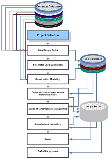
Figure 1.
General structure of parametric computer-aided design system.
Experience in the field of computer-aided systems for parametric structure design made it possible to determine the necessary blocks of tasks that should ensure the effective use of such systems in the design bureau practice:
- Block of general design tasks.
- Block of constructional modeling.
- Block of procedures for designing various hierarchical levels structures.
- Block of procedures for designing reinforcement structures.
- Block of verification calculations of structural strength.
- Block of creation of the reporting documentation.
- Block of transferring design results to the CAD-CAM system of the design bureau.
Effective automation of the parametric design of hull structures is not possible if a number of general design tasks have not been solved previously. The task list is presented in Figure 2. Before starting work, it is necessary to select a project. It can be one of the projects that have already been worked on or a new one.
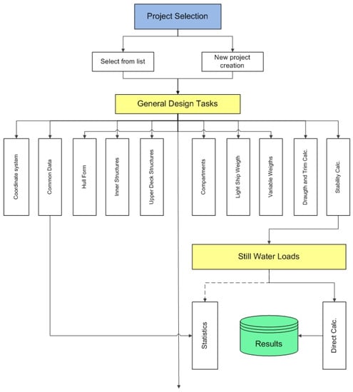
Figure 2.
General design block of the parametric computer-aided design system.
Determination of the coordinate system is one of the fundamental problems that must be solved. The block of general data determining is intended to generate information such as the ship type, operating limits, ice-strength class, and life cycle. The main ship dimensions, computational length, block coefficient, and displacement constitute the next group of general data. Furthermore, the parameters of superstructures (deckhouses) are set, and their construction type is determined.
The block of the ship hull geometry description is one of the key factors in the computer-aided design system. The hull geometric modeling problem can be solved by various methods: Importing a geometric model created by other systems (for example, AVEVA, FORAN); data entry point by point, which defines the geometry of each frame section; and geometric model creation by transforming the shape of the prototype ship hull. The block operation result is a ship hull wireframe model (Figure 3).
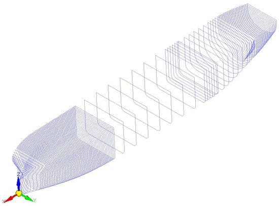
Figure 3.
Ship hull wireframe model.
Concerning the block of internal structures’ geometry description (inner bottom, inboard, intermediate decks and platforms, longitudinal and transverse bulkhead, etc.), the need for such an information block in the system is obvious. The structure’s shape is one of the most important characteristics that directly affects its structural arrangement and design calculations results. In the present computer-aided design system, a method of simplified description of the internal structures’ geometry was implemented, which is specified by the values of parameters in the so-called control sections. The control section is considered to be the one in which the characteristic shape parameters of the present structure can be easily determined, or even set by specific dimensions borrowed from the general arrangement drawings. The shape parameters between control sections are determined by the linear interpolation method. Special software makes it possible to obtain a parametric description of the internal structures’ geometry in the form of planes or triangulated surfaces (Figure 4). Structures that spill over the body surface are automatically “cut off” along the intersection line.
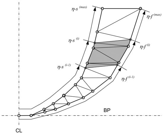
Figure 4.
Wireframe triangulation of ship surfaces.
The block of superstructures’ geometry description. The superstructures’ geometry can be set in the block of the ship hull geometry description. In the proposed computer-aided system, it is possible to represent each superstructure geometry as a separate geometric object, with its description in the same format as the main hull. Such a methodical approach expands the possibilities of geometric modeling, including in relation to the complex stroke of the main hull (bulbous bow, skegs, stern-post elements, etc.). The solution to the problem of construction modeling of upper deck sections under deckhouses and the visualization of its results is simplified. The possibility of construction modeling and parametric design of superstructures (deckhouses) is provided, regardless of the main hull.
The block of ship compartments/tanks description. The ship compartments’ geometric characteristics are used in the problem of the ship variable load layout for the purpose of following calculations of the ship draft and trim and the loads on the hull in still water. The list and purpose of ship spaces/compartments are generated in the process of creating a current project database. In addition to geometric parameters, the block of ship compartments/tanks description includes the following information: The load type in the compartment, stacking height of general or timber cargo, the level of the free surface of liquid or bulk cargo, the value of the stowage factor, or the average cargo density. For bulk cargo, the angle of internal friction is additionally set. Compartment loading information can be obtained from the data on a permissible double bottom or deck load. For tanks, there is also the introduction of parameters, which make it possible to determine the test load value.
The block of light ship load layout. The light ship load layout is one of the problems that is associated with significant difficulties, especially in the early stages of ship design. These difficulties are due to the lack of initial information. In the proposed computer-aided system, the light ship load formation can be carried out in two ways:
- Manual data entry in the presence of relevant initial information—load tables.
- Calculation of load components according to statistical dependencies—in the absence of load tables.
The block of variable load layout. The layout of the variable load is implemented in an interactive mode. A special interface allows one to select a concrete compartment from the corresponding database of the current project to indicate the cargo type, its characteristics (stowage factor or density, angle of internal friction, etc.), the amount of cargo in it, or the filling percentage.
The block of equilibrium draft and trim calculation allows one to evaluate the permissibility of the accepted ship loading variant by the value of the average draft and trim.
The block of ship stability calculating allows one to conduct additional checks of the permissibility of the accepted ship loading variant by the parameters of initial stability, stability at a large heeling angle, or by the value of the weather criterion. The presence of geometric hull and superstructure models makes it possible to automate the calculation of the lateral projection area, the parameters of which must be known for stability calculations.
The information prepared by the previous blocks is used in the block of still-water load calculations. The software created during the development of the computer-aided system makes it possible to perform the still-water load calculations with general load distribution and the actual ship position on the water. The ship weight distribution can be represented as a stepped configuration. There are software-implemented procedures for still-water load calculations with the actual weight load distribution, which is obtained as a result of the operation of the following blocks: The block for the light ship load layout and the block for the variable ship load layout (Figure 5). The results for still-water load calculations for all variants of ship loading are stored in the database.
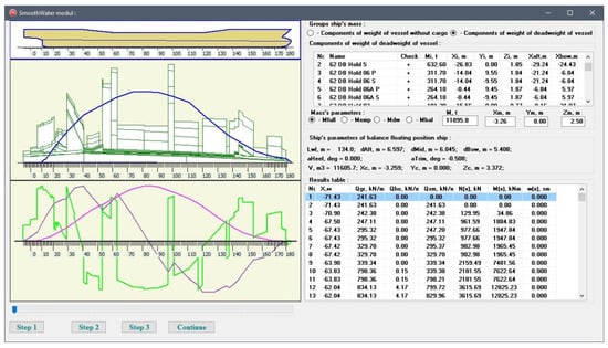
Figure 5.
Calculations of still water loads based on the actual distribution of the light ship and variable ship loads.
The block of construction modeling. The computer-aided system provides the possibility of implementing three modes of hull construction modeling:
- Structure modeling in a given cross-section.
- Hull modeling by describing the design of each of its structural components (substructures).
- Hull modeling by describing the “structural compartment” (a set of substructures bounded by transverse planes passing through given practical frames).
The first modeling mode is convenient in cases where it is necessary to obtain information about the structural element dimensions only in a given cross-section over the length or in a set area with a characteristic (unchanged) topological (structural) scheme (Figure 6). The modeling of hull structures in a given cross-section is provided by a specialized editor that allows one to interactively divide plate structures into separate plates, arrange the longitudinal stiffeners and primary support members, and assign the dimensions based on the design calculation results.
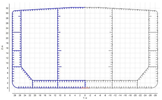
Figure 6.
Structural modeling of the ship hull cross-section (first mode).
The second modeling mode allows one to describe the structural scheme of the substructure as a whole (the upper deck, intermediate deck, platform, inner bottom, shell expansion along their entire length, etc.) or its separate parts in a given area (Figure 7). Structural modeling of the outer shell and internal hull structures is implemented by various software blocks due to the modeling algorithms’ features. The presence of structural modeling created by the second-mode software makes it possible to obtain a structural model of the hull cross-section in the plane of a given frame or in a plane with a given X-coordinate by processing the database information on the hull design.
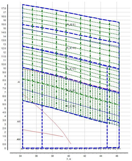
Figure 7.
Structural modeling of the ship hull (second mode).
The third design mode allows one to obtain a description of the hull at the level of the structural compartment. In practice, it is implemented as an assembly of the results of structural modeling of the outer shell and internal hull substructures (separate parts of the outer shell and internal substructures). The structural modeling results can be used to perform structural verification calculations via the method of finite element analysis of the hull strength at the level of a compartment and up to three compartments in total.
Such an analysis has to be performed in some design cases, for example, with an alternating pattern of heavy cargo loading of a bulk carrier hold, when analyzing the deck displacement in its plane for an RO-RO ship, when assessing the hull tension in local areas, etc.
The block of various hierarchical levels’ structure designing implements the parametric design concept proposed in the work, based on the successive complication of models and design algorithms. At this stage, the design procedures based on the requirements of the Rules common to all ships are implemented: The design of outer shell plating, bottom and side framing for sea water pressure, design of deck structures, double bottom for cargo pressure, etc.
In accordance with the parametric design concept based on the ship hull decomposition and the successive complication of models and design algorithms, the block of structural design can be divided into three levels:
- Level of substructure elements design.
- Level of design of the structure as a whole.
- Level of a set of structures design.
Each level has its own models and structural design algorithms.
At the first (lower) level, procedures of plates and beam structural elements’ (stiffeners) parametric design are implemented according to the requirements for local strength and buckling using the simplest models. The design begins with plate elements. The results of this design stage are then used in beam element design since the plate element design parameter (plate thickness) is the thickness of the attached plate of the beam element.
At the first design level, the requirements for local strength and buckling of plates and beams can be only implemented as a first approximation, since the allowable stresses from local bending, as well as the calculated compressive forces and shear loads that can lead to collapse, are dependent on the structural element dimensions defined in the higher design levels.
In most cases, when solving design problems of the first level with a given layout scheme and selecting structural elements material, calculated dependences can be directly found relative to the desired structural element parameters. More complex computer-aided design procedures for plate and beam elements can be used to justify the layout scheme of the structure (choosing a framing system or scheme of arrangement of stiffening elements) and the choice of material strength. The need to solve such problems may arise at the early (research) stages of ship hull structure design. The structure of the requirements for sheet and beam structural elements is such that it is expedient to formulate these problems in the form of nonlinear programming problems with constraints.
At the second level, procedures of plate and beam structural elements’ parametric design are implemented according to the requirements for local strength and buckling using models of a higher hierarchical level: Plane beam systems, structurally orthotropic plates, and the complex plane web frame system (transverse frame and other frames). In most cases, at this stage, there are primary supporting members of structures designed (web frames, girders etc.). Ordinary beams (stiffeners) can either be ignored or included as a component of their (web beams) attached plates.
Such design models usually do not provide an unambiguous solution. Regulatory requirements for strength and/or buckling can be provided, with various combinations of structural elements dimensions. Therefore, it is advisable to use search procedures at this design stage. Structure behavior modeling using the design of experiments method can improve the efficiency and simplify the solution of such a problem.
At the third (highest) level, procedures for parametric structural design are implemented according to the requirements for buckling, strength, and stiffness in the cause of ship hull general deformation (during general bending). The hull model used at this stage is a hull girder. The model is formed on the basis of the construction modeling results contained in project database tables. The results of structural design, obtained in the first two levels, are used as initial data. The design of the hull structure is carried out in two stages:
- Verification calculation of the hull girder; analysis of compliance with the requirements for strength, stiffness, and buckling during general bending.
- Correction dimensions of certain longitudinal elements of the hull if the conditions of general strength and/or stiffness and/or buckling are not met.
In the second case, the structural design is implemented in the form of a search procedure.
The block of structural reinforcements design (ice strengthening, slamming strengthening, etc.). Hull reinforcements, caused by additional external efforts or architecture and structural features (the presence of cutouts, deckhouse endings), apply to the corresponding hull areas. Reinforcements can extend to a small area—these are considered local reinforcements (cutouts areas, deckhouse endings, etc.). In some cases, the extent of the reinforcement area is significant (ice reinforcements, reinforcements for load accommodation during slamming, etc.). The requirements for hull reinforcement structures are singularized into separate sections in the regulatory documents (Rules of Russian Maritime Register of Shipping). Accordingly, additional software is also provided in the computer-aided design system.
The block of verification calculations of strength is intended for solving design problems in the verification calculation mode. This approach is appropriate for tasks that require complex structural modeling (for example, based on FEM), which can be solved only with known (given) values of structure elements’ dimensions. This block provides the possibility of solving a problem using search procedures and modeling on the basis of the general approach based on the methodology of numerical experiment planning.
3. The General Structure of the Database and the Methodological Foundations of Its Formation
The organization of the process of parametric computer-aided design is greatly simplified with the presence of a database. As a part of the system, it is advisable to have a common database and a database of the project on which the user is working. In the present computer-aided system, a database is understood as a set of information blocks organized in the form of files of various structures and formats. The file structure is ordered in a certain way: A directory, folder, or workbook.
In a common database, it is advisable to store information (by definition) of a general nature, which can be used to form a database for a specific project for ships of various architectural and structural types. The experience of system development has shown that, in order to solve the problems of ship hull structure design, the common database should contain the following information blocks:
- General hierarchical directory of structures.
- Directory of ship compartments/tanks.
- Directory of ship structures material grades.
- Assortment of plates, profiles, and standardized compound profiles (T-profiles).
The structure of the common database should be able to grow as the system improves and its functionality capabilities expand.
The general hierarchical directory of structures (Figure 8) is necessary for the implementation of the initial stage of database formation according to the specific project hull design. The directory structure corresponds to the accepted general structural decomposition of the ship hull, which does not contradict the ship hull design fundamentals. A rigidly fixed hierarchical system of structural element coding is associated with the structural decomposition of the ship hull. Formalization of the requirements of the applicable rules to the present hull structures is carried out on the basis of the structural elements code. The top-level directory (Figure 9a) can be supplemented with new groups of structural components. Catalogs of lower levels (Figure 9b) are formed, taking into account the following fundamental principle—the directory structure should be as unified as possible for different groups of structures, even if this leads to code redundancy (i.e., some code levels may never be used).
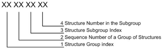
Figure 8.
Ship structure classification.
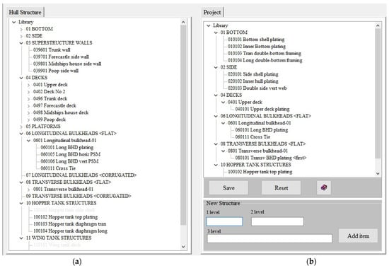
Figure 9.
General hierarchical structure directory: (a) Directory of top-level structural groups; (b) directory of structural groups of second and third levels of the present project.
The directory of the current (specific) project is created in accordance with the following algorithm:
- The formation of the structure list showing the actual construction decomposition of the project hull structure.
- The coding of selected structures.
The formation of the structures list is carried out in the process of selecting the desired structure from the general hierarchical structure directory. At the same time, the user works with the text variables that reflect the generally accepted names of ship structure elements: “Bottom plate”, “Shearstrake”, “Deck stringer”, “Frame”, etc. The coding of selected structures is carried out automatically. A portion of code is generated that uniquely determines the selected structure (Figure 8).
Parametric provisioning of the database on the ship hull design is performed at the stage of ship hull structural modeling, using a specialized interface and software. To solve this problem, it is first necessary to perform the database formation according to the geometry of the hull and its structural components.
To create a database on ship compartments/tanks, materials, and assortments, the following general approach is used:
- When developing a common system database, there is a general directory created for compartments/tanks of the ship hull, ship structure materials, and an assortment of plates and profile materials.
- According to the general design documentation, a hierarchical directory of the compartments/tanks of the ship under consideration is created.
- Based on the hull design documentation, lists of the materials used, types and dimensions of profiles used for the frame beam manufacturing, and standard sizes of plate products are created; when designing a new ship, the restrictions associated with the ordered material for ship construction must be taken into account.
- The formation of a database of compartments/tanks, materials, and assortments for a specific project is reduced to selecting the corresponding records (rows) from the common database tables in an interactive mode. As a result, project directories are formed, with which the system then provides the opportunity to work. Usually, these directories are much smaller than the original ones. This fact simplifies the working conditions.
In this article, as an illustration of the proposed methodological approach, the creation of a Directory on ship compartments/tanks is considered. Classification of the ship compartments/tanks is proposed, mainly focused on the tasks of ship structure design, as well as the structure of a general directory of ship compartments/tanks (Table 1). A “truncated” directory is created, the structure of which reflects the needs of civil ship structure design (Figure 10).

Table 1.
Classification of the ship compartments/tanks.
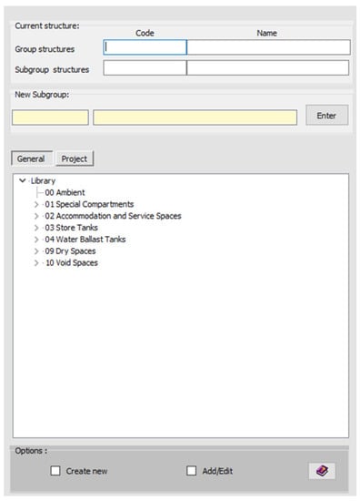
Figure 10.
Top-level directory (compartments groups).
Each compartment/tank of the ship hull has a unique code, which generally consists of eight digits (Figure 11).
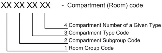
Figure 11.
Ship structure classification.
The directory includes a group with code 00, which defines the conditional compartment “Ambient <environment>”. The presence of such a code makes it possible to automate the calculation of the corrosion wear rates of the elements of the outer shell plating and open decks.
Group 01, “Special spaces”, is for cargo ships, and combines various subgroups and groups of cargo compartments (see Table 2).
Table 2.
Subgroups and groups of ship compartments/tanks.
Group 02, “Service spaces”, in the system of computer-aided design of civil ship structures, includes only engine and boiler spaces since the register rules impose a number of additional requirements on hull structures in these ship areas.
Subgroups of spaces related to groups 03–04 and 07–09 can be divided into types (for example, 030101—reserve bunker oil tank, 030102—daily bunker oil tank, etc.), but this information will be redundant in the case of computer-aided structural design. Therefore, such a code hierarchy is not provided for these compartment groups. In addition to the unique hierarchical (numerical) code for each ship hull compartment/tank, a supporting letter code (automatically generated) is provided, which allows the user to freely navigate the compartment type, since it has a mnemonic meaning.
The general directory of the ship hull spaces/compartments can be supplemented or edited.
Figure 12 shows the results of the creation of a directory of a particular ship’s compartments/tanks. For this purpose, the groups, subgroups, and compartments/tank types that are in the present project are selected from the general directory of the ship compartments/tanks.
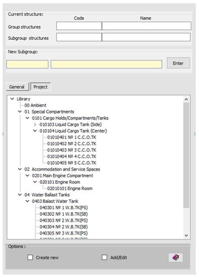
Figure 12.
An example of the created <Current Project Directory> in expanded form.
After compartments/tanks creation, it is necessary to set their parameters, which will be needed to perform the design procedures for the ship structure design. To solve this problem, specialized software is used.
4. Project Database
The experience of developing a computer-aided design system and solving a large number of practical problems in the field of ensuring ship operation and design works made it possible to form an idea of the structure of the project ship design database (Figure 13).
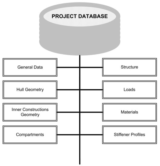
Figure 13.
The structure of project database.
General project data (ship type, ice class, main dimensions, sign of coordinate system attribute, spacing table, etc.) are contained in several text files.
The hull geometry is stored as a text file in a format that defines the geometry of a set of cross-sections or a ship hull “wireframe”. The hull geometry can be visually viewed in two-dimensional and three-dimensional modes in a special editor (Figure 14).
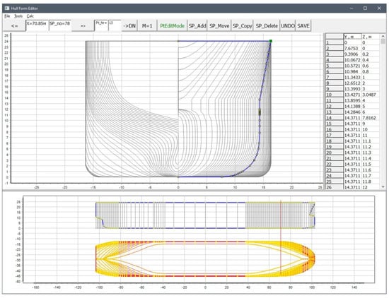
Figure 14.
Visual representation of the hull geometry in a special editor.
The geometry of internal structures is stored in the form of text files containing information regarding internal structure control sections (Figure 15) and the values of the parameters that determine the shape of these structures in a given ship hull section. In Figure 16, as an example, the results of geometric modeling of the transverse bulkhead of an ice-going tanker are presented.
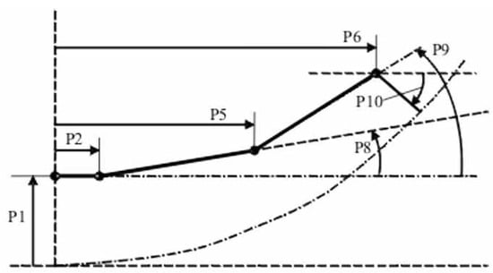
Figure 15.
An example of the parameters of the inner bottom control section. Here P1–P6—parameters that determine the shape of the internal structure in the considered section of the vessel along its length (dimensions, angles of inclination).
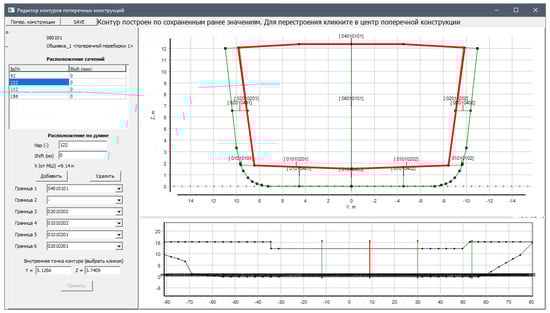
Figure 16.
The results of geometric modeling of the tanker transverse bulkhead.
Compartments/Tanks. The list of compartments/tanks of the project is stored in a text file in the form of a hierarchical tree. Each compartment has a unique hierarchical code. The parameters of all the described compartments are collected in a text file in the form of data blocks starting with a unique compartment code. This file contains all the necessary information for design calculations.
Hull Structure. This is the most complex data block. Information in the form of text files set is stored in the “HullShip_Structure” project folder.
Lightweight and Variable Loads. Lightweight ship components and deadweight (variable) components are placed in text files, the number of which is equal to the total number of loading options considered (Figure 17).
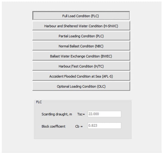
Figure 17.
Ship load cases.
Project materials directory. Information about the project material, obtained in accordance with the algorithm discussed in point 3, is placed in a text file. The file structure in relation to one of the projects is presented in Table 3.
Table 3.
Project material catalog.
Profiles. Information about the standard sizes of profiles used in the project, obtained in accordance with the algorithm discussed in point 3, is stored in a text file. The file structure is shown in Figure 18.
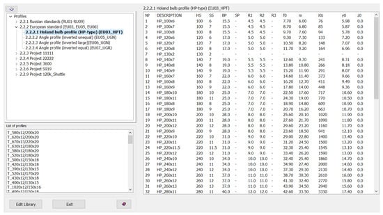
Figure 18.
Profiles.
5. Conclusions
Ship hull structure design can be represented as a combination of two interlinked processes—computer-aided construction and parametric design. Construction is intended for the formation of visually parameterized information about the structural design composition of hull structures, as well as their geometric and construction concepts. One of the design tasks is the development of structural drawings using modern office equipment. Parametric computer-aided design is intended to determine the dimensions of structural elements that meet regulatory requirements. The parametric design of ship hull structures is carried out on the basis of the requirements of the Rules of Classification Societies/Structures strength standards.
When designing ship hull structures in the design bureau, many calculations are performed. To perform them, as a rule, highly trained specialists are involved. The parametric design process is iterative. At the same time, the hull design can change many times, which requires changes in the dimensions of structural elements and, as a consequence, repetition of design calculations. In this regard, automation of the parametric design, based on specialized software, is of great importance.
Experience in scientific research and solving practical problems in the field of designing ship hull structures, floating docks, and surface ships, accumulated over more than 30 years, made it possible for the authors to form an idea about the general structure of the parametric computer-aided structural design, the composition of functional soft blocks, the level of detail of the design object (ship (offshore structure) hull) description, and its structures and methodological foundation for its development. The generalization of the obtained representation is as follows:
- The structure of the computer-aided design system is determined by a set of soft blocks and their interrelation, the functional type of each block (the totality of problems to be solved), and the sequence of program procedure implementation.
- It is expedient to have a common database as part of the parametric computer-aided system for ship hull structure design. The common database stores information that is (by definition) common to ships of all projects.
- The availability of a common database and specialized software makes it possible to form a project database and ensure the convenience and simplification of the functional soft blocks’ development and the organization of the parametric design process.
- Catalogs (or classifiers) of ship structures, compartments/tanks of the ship hull, data on materials, and profiles are of great practical importance.
- It is fundamentally important to develop a special system for coding the ship hull structure elements and ship hull spaces. Such information is absolutely necessary for the development of the program code of the computer-aided system modules.
Author Contributions
Conceptualization, methodology, V.N.T.; project administration, V.N.T.; system structure, software, analysis, S.N.R.; writing the draft article, S.N.R.; editing the article, V.N.T. All authors have read and agreed to the published version of the manuscript.
Funding
This research was carried out as a part of the strategic academic leadership program “Prioritet-2030” for the period 2021–2022 and beyond until 2030, funded by the Ministry of Education and Science of the Russian Federation and as part of the World-class Research Center program: Advanced Digital Technologies (contract No. 075-15-2020-903 dated 16 November 2020).
Data Availability Statement
Not applicable.
Conflicts of Interest
The authors declare no conflict of interest. The funders had no role in the design of the study; in the collection, analyses, or interpretation of data; in the writing of the manuscript, or in the decision to publish the results.
References
- Available online: https://www.autodesk.com/ (accessed on 1 April 2022).
- Available online: https://ascon.ru/ (accessed on 1 April 2022).
- Available online: https://www.plm.automation.siemens.com/global/en/products/foran/ (accessed on 1 April 2022).
- Available online: https://www.aveva.com/ (accessed on 1 April 2022).
- 2D Ship Structural Assessment Software. Available online: https://marine-offshore.bureauveritas.com/mars-2000-2d-ship-structural-assessment-software (accessed on 1 April 2022).
- Available online: https://www.veristar.com/portal/veristarinfo (accessed on 1 April 2022).
- Ship Structural Analysis and Design—Nauticus Hull. Available online: https://www.dnv.com/services/ship-structural-analysis-and-design-nauticus-hull-1061 (accessed on 1 April 2022).
- Strength Assessment of Hull Structures—POSEIDON. Available online: https://www.dnv.com/services/strength-assessment-of-hull-structures-poseidon-18518 (accessed on 1 April 2022).
- Engineering Software. Available online: https://ww2.eagle.org/en/rules-and-resources/engineering-software.html (accessed on 1 April 2022).
- Aleksashin, D.; Boyko, M.; Kuteynikov, M.; Sotskov, S. IACS Common Structural Rules development and RS design verification during ship plan approval. Trans. Krylov State Res. Cent. 2018, 2, 59–63. [Google Scholar] [CrossRef]
- Papanikolaou, A. A Holistic Approach to Ship Design. Volume 1: Optimisation of Ship Design and Operation for Life Cycle; Springer Nature Switzerland AG: Athens, Greece, 2019; pp. 24–26, 231–233. [Google Scholar] [CrossRef]
- Papanikolaou, A. A Holistic Approach to Ship Design. Volume 2: Application Case Studies; Springer Nature Switzerland AG: Athens, Greece, 2021; pp. 340–345. [Google Scholar] [CrossRef]
- Suh, S.-W.; Kang, W.-S.; Lee, K.-Y.; Lee, K.-O. A study on the data structure and implementation techniques for the object oriented ship structure modeling. J. Soc. Nav. Archit. Korea 1994, 31, 1–11. [Google Scholar]
- Roh, M.-I.; Lee, K.-Y.; Yoo, S.-J. An algorithm for generating the hull structural analysis model using the seam information of the hull structure at the initial design stage. J. Ship Ocean Technol. 2006, 10, 24–33. [Google Scholar]
- Shigehiro, M.; Masahiro, M.; Song, X.; Takao, Y. Structural optimization of the mid-ship section by applying genetic algorithm and response surface method. J. Jpn. Soc. Nav. Arch. Ocean Eng. 2014, 20, 109–117. [Google Scholar] [CrossRef][Green Version]
- Lee, K.-Y.; Lee, W.-J.; Roh, M.-I. Development of a semantic product modeling system for initial hull structure in shipbuilding. Robot. Comput. Manuf. 2004, 20, 211–223. [Google Scholar] [CrossRef]
- Roh, M.-I.; Lee, K.-Y. An initial hull structural modeling system for computer-aided process planning in shipbuilding. Adv. Eng. Softw. 2005, 37, 457–476. [Google Scholar] [CrossRef]
- Na, S.-S.; Karr, D.G. Development of Pareto strategy multi-objective function method for the optimum design of ship structures. Int. J. Nav. Arch. Ocean Eng. 2016, 8, 602–614. [Google Scholar] [CrossRef][Green Version]
- Jang, C.-D.; Na, S.-S. Development of optimum structural design system for double hull oil tankers. J. Soc. Nav. Archit. Korea 2000, 37, 118–126. [Google Scholar]
- Nobukawa, H.; Zhou, G. Discrete optimization of ship structures with genetic algorithms. J. Soc. Nav. Archit. Jpn. 1996, 179, 293–301. [Google Scholar] [CrossRef][Green Version]
- Tryaskin, V.N.; Ryumin, S.N.; Kuteynikov, M.A. The ATLAS Software. Objective and Architecture. Methodological Basis. Test Results; Reseatch Bulletin by Russian Maritime Register of Shipping, №54/55; Russian Maritime Register of Shipping: Saint-Petersburg, Russia, 2019; pp. 106–127. [Google Scholar]
- Russian Maritime Register of Shipping. Rules for the Classification and Construction of Sea-Going Ships; Russian Maritime Register of Shipping: Saint Petersburg, Russia, 2021. [Google Scholar]
- IACS. Common Structural Rules for Bulk Carriers and Oil Tankers; IACS: London, UK, 2021. [Google Scholar]


Publisher’s Note: MDPI stays neutral with regard to jurisdictional claims in published maps and institutional affiliations. |
© 2022 by the authors. Licensee MDPI, Basel, Switzerland. This article is an open access article distributed under the terms and conditions of the Creative Commons Attribution (CC BY) license (https://creativecommons.org/licenses/by/4.0/).