Article

Electrically Driven Lower Limb Exoskeleton Rehabilitation Robot Based on Anthropomorphic Design

1
School of Mechatronic Engineering, Changchun University of Technology, Changchun 130012, China
2
Institute of Electromechanical Technology, Jilin Academy of Agricultural Machinery, Changchun 130021, China
*
Author to whom correspondence should be addressed.
Machines 2022, 10(4), 266; https://doi.org/10.3390/machines10040266
Submission received: 15 March 2022 / Revised: 31 March 2022 / Accepted: 6 April 2022 / Published: 7 April 2022
(This article belongs to the Section Robotics, Mechatronics and Intelligent Machines)

Abstract

:
To help people with impairment of lower extremity movement regain the ability to stand and walk, and to enhance limb function, this study proposes an anthropomorphic design of an electrically driven, lower-limb exoskeleton rehabilitation robot. The angular range of the robot’s motion was determined according to the characteristics of the targeted lower-limb joints; the robot was given an active–passive anthropomorphic design with 12 degrees of freedom. The multi-degree-of-freedom hip exoskeleton, bionic artificial knee exoskeleton and passive rigid-flexible coupling ankle exoskeleton can assist patients in rehabilitation exercises with better wear comfort and exercise flexibility. A kinetic model of the seven-rod lower-limb exoskeleton rehabilitation robot was built, and data analysis of the dynamically captured motion trajectory was conducted. These provided a theoretical basis for gait planning and the control system of the lower-limb exoskeleton rehabilitation robot. The results show that the lower-limb exoskeleton rehabilitation robot system possesses sound wearing comfort and movement flexibility, and the degree of freedom of movement of the exoskeleton robot matches well with that of human movement. The robot can thus provide effective assistance to patients’ standing and walking rehabilitation training.

1. Introduction

With rapid socio–economic development and the continuous improvement of peoples’ health and living standards, the proportion of elderly people is rapidly increasing. According to the “Report on World Population Trends” (the Report) released by the 51st session of the United Nations Commission on Population and Development, the number of people aged over 65 will exceed 1.5 billion by 2050. Social aging has gradually become a universal trend. Included with the problems of aging, physical function of the elderly gradually decreases and lower extremity disease has also increased [1]. Further, there is an increasing incidence of lower-limb neurological injuries, hemiplegia, lower-limb weakness and movement disorders caused by unhealthy lifestyles, traffic accidents and sports injuries [2,3]. This situation has brought a heavy burden to society and families. Therefore, it is imperative to seek effective means of rehabilitation to enable patients to restore their lost standing and walking functions to a certain extent, thus regaining self-care abilities and ultimately even be fully able to stand and walk.
Currently, two types of rehabilitation training are commonly used in these patients: standing and walking. The aim is to train the regulation functions of the neural system and to enhance the memory of the muscle tissue in order to prevent the atrophy of lower limbs caused by long-term nonuse [4]. Traditional lower limb rehabilitation training—due to the low availability of automated training devices—requires the assistance of rehabilitation teachers for the entire process. The limited number and energy of rehabilitation teachers leads to problems such as expensive training and short training time [5]. Therefore, using mechanical devices with high repeatability and precision instead of traditional rehabilitation training equipment can improve the efficiency of rehabilitation and solve the above problems. With the continuous optimization and improvement of rehabilitation medical institutions, rehabilitation medical equipment has provided more comfortable and better services to patients than ever before [6]. However, the problem of wearable lower-limb rehabilitation medical equipment that can help train patients to stand and walk has not been fully solved. Therefore, it is urgent to help patients have a reasonable means to rehabilitate and walk again with assistive devices.
The development of lower-limb exoskeleton rehabilitation robots is a great benefit for people with special needs of lower-limb movement. With the lower-limb exoskeleton rehabilitation robots, patients are able to perform medical rehabilitation training to achieve normal walking and enhance quality of life [7]. Since the proposal of the exoskeleton rehabilitation robots, they have been actively researched and developed in many countries. Examples of advanced lower-limb exoskeleton rehabilitation robots in the world include LokomaT [8] and Walkbot [9]—movable lower-limb exoskeletal robotic system. They were among the first rehabilitation devices in the world to be successfully used in rehabilitation medical institutions to help patients with rehabilitation training. Later, Ekso Bionics Company developed Ekso TM. This is a medical gait-training exoskeleton for patients with varying degrees of paralysis and hemiplegia [10]. In addition, a research and development group at Vanderbilt University developed a lower-limb exoskeleton called Indego to help paraplegics and stroke patients walk [11]. Further, Argo Medical Inc. developed RewalkTM to provide powered hip/knee movements for paraplegics to stand and walk [12]. These lower-limb exoskeleton robots have flexible hip, knee and ankle joints similar to that of the human lower limbs, as well as a large assistive support frame to provide support during patient training. The main target population is the rehabilitation of hospital patients and persons with disabilities. In the development of lower-limb exoskeleton rehabilitation robots, the last decade has seen a significant improvement in every aspect of the system, with the Hybrid Assistive Limb (HAL) series of exoskeletons developed by Japanese company Cyberdyne Inc. relatively representative [13,14]. The HAL exoskeleton uses the wearer’s own electromyographic signal amplifier to estimate joint torque in order to output assisted torque, thus enabling the wearer to control movement. Furthermore, apart from HAL, a large number of rehabilitation aids have emerged in recent years, such as AILEGS by Beijing AI-Robotics Ltd. (Beijing, China) [15], Shanghai Fourier M2 by Fourier Technology Ltd. (Chatswood, Australia) [16] and Rex by Rex Bionics Ltd. (London, UK) [17]. Currently, R&D organizations have developed a variety of walking rehabilitation aids to help patients. Some of these are rehabilitation robotic systems fixed on treadmills to assist patients with weight-reduction training. Although these exoskeleton rehabilitation devices can be used for various types of rehabilitation aids, the majority of them are still limited to rehabilitation facilities with a fixed training mode of walking, which shows poor applicability to the patient.
A lower-limb exoskeleton rehabilitation robot is a combination of robot technology and medical rehabilitation technology. In terms of machinery, the design of the exoskeleton should not only combine rigid and flexible structures, but also have a high degree of resemblance to the joints of the human body [18]. However, there are still many problems with existing lower-limb exoskeletons, which traditionally use a thick, bulky support frame with a low degree of freedom to support part of the wearer’s weight and mobility. To improve comfort during use, the devices are designed to fit closely to the wearer’s limbs. However, if the rigid support frame and mechanical components are tightly fitted to the body, they may cause movement discomfort during rehabilitation training and are more likely to cause secondary injury to patients (although in recent years flexible exoskeleton devices have been able to assist patients in achieving natural human gait characteristics and assist with lower-limb rehabilitation exercises in comfort [19,20]). However, these devices have not been able to provide stabilizing support until now, which is essential, considering the importance of auxiliary support for people with lower-limb movement disorders and lower-limb weakness. Thus, a flexible exoskeleton rehabilitation device is still not the optimal choice. Therefore, by examining the structural characteristics of different types of rehabilitation robots, the discomfort caused by mismatch between rehabilitation movements in different rehabilitation stages can be effectively avoided. Existing lower-limb exoskeleton rehabilitation robots also have problems such as large gaps between robot mechanical structure and human physiological structures, poor rehabilitation comfort and ineffective utilization of rehabilitation resources [21]. Wearing an appropriate exoskeleton robot can effectively help the wearer carry out rehabilitation training to achieve normal standing and walking. At the same time, the development of exoskeleton robots for lower-limb rehabilitation not only eases the pressure on families and society to a certain extent, but also contributes to the development of the entire healthcare and protection system of the society.
In this study, an anthropomorphic, multi-degree-of-freedom (DOF), electrically driven lower-limb exoskeleton rehabilitation robot walking aid was designed to assist people with lower-limb movement disorders by providing moderate assistive training for standing and walking as well as to promote functional strength. This study is based on an innovative anthropomorphic design approach for lower-limb exoskeleton rehabilitation robots. With an in-depth understanding of the drawbacks of traditional rehabilitation training and the performance of rehabilitation robots, an anthropomorphic hip, knee and ankle exoskeleton structure was designed according to the principles of rehabilitation medicine and anthropomorphic design. A kinetic model simulation analysis and dynamic trajectory-capture data analysis for the lower-limb rehabilitation robots was conducted. The system was designed for passive rehabilitation training of the lower-limb exoskeleton robot. The rationality of the lower-limb exoskeleton rehabilitation robot system was verified through the experiment of standing and walking of the wearers.
The main contributions of this paper are summarized as follows:
(1)
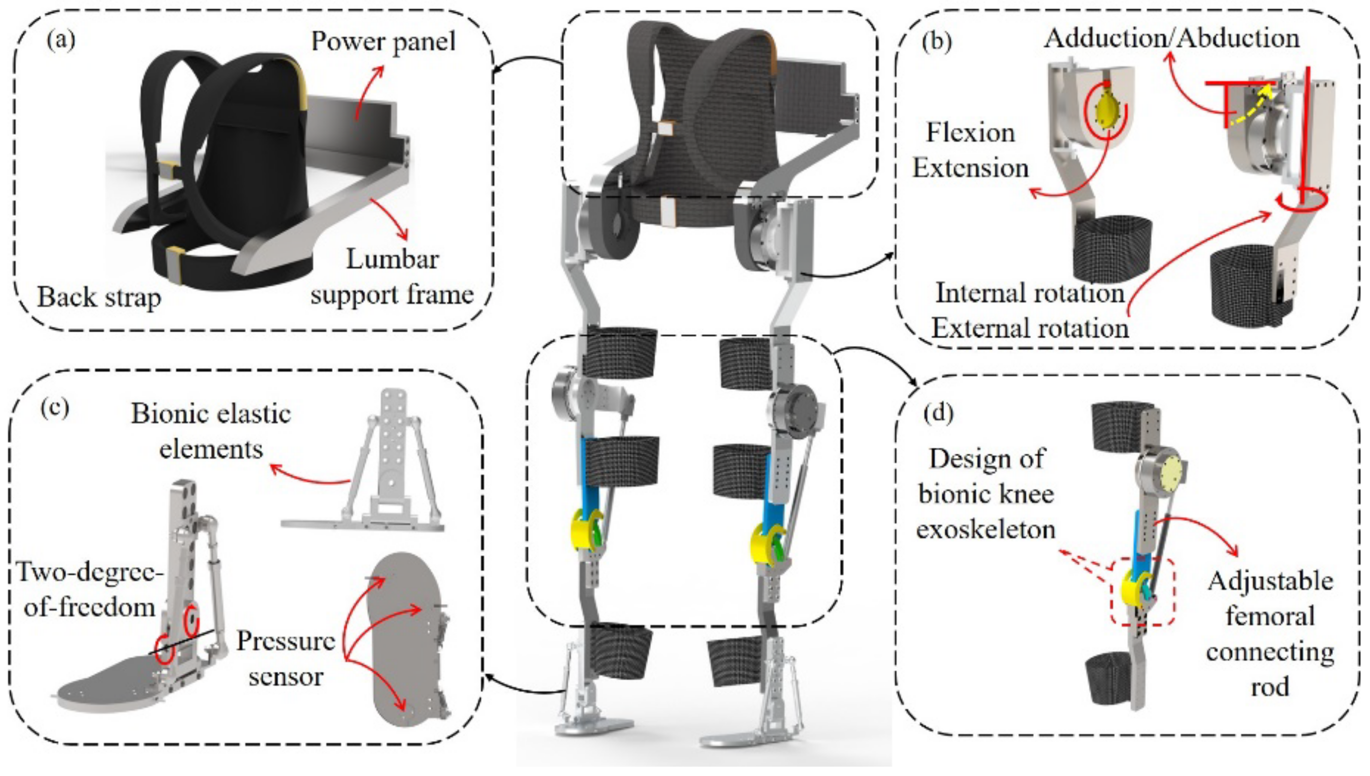
An anthropomorphic, multi-degree-of-freedom (DOF), electrically driven lower-limb exoskeleton rehabilitation robot walking aid was proposed. The robot adopted an active–passive anthropomorphic design with 12 degrees of freedom. The multi-degree-of-freedom hip exoskeleton, bionic artificial knee exoskeleton and passive rigid–flexible-coupling ankle exoskeleton can assist patients in rehabilitation exercises with better wear comfort and exercise flexibility. The innovative anthropomorphic structural design method will play an important reference role in assisting lower-limb exoskeleton rehabilitation training and also provide theoretical support for the optimization and upgrading of lower-limb exoskeleton rehabilitation robots.
(2)
Based on the Lagrange mechanics method, the dynamic model of a seven-bar lower-limb exoskeleton rehabilitation robot and data analysis of dynamic trajectory capture were established, and the accuracy of exoskeleton robot motion is verified by simulation analysis. The control system of passive rehabilitation training for the lower-limb exoskeleton rehabilitation robot was designed. The wearing comfort and movement flexibility of the lower-limb exoskeleton rehabilitation robot system were verified by having test subjects wear the device, confirming it can provide adequate assistance for patients in standing and walking rehabilitation training.

2. Biomechanical Analysis of the Human Body

2.1. Design Concept

The concepts of anthropomorphic design and bionic theory have been introduced into the development of structures to provide wearers with a comfortable range of motion and safe performance. Through analyzing the biomechanical properties of the human body, this study aims at approximating the characteristics of natural human gait as closely as possible and increasing the range of motion of the exoskeleton robot. In the design of lower-limb exoskeleton rehabilitation robots, factors such as the number of degrees of freedom, structural forms, actuation method and wearable mode are all taken into consideration [22]. Therefore, according to the human motion base plane (Figure 1), it can be broadly assumed that the movements of joints in the sagittal plane, including flexion and extension, are predominant in activities such as walking, running, squatting, standing, climbing downstairs, etc. Furthermore, most existing lower-limb exoskeleton robots have motors placed at different joints. For this reason, the structure of the lower-limb exoskeleton rehabilitation robot we propose has six degrees of freedom (DOF) in each leg. Three of these degrees of freedom are at the hip joint, one at the knee joint and two at the ankle joint. The hip and knee joints are designed as active joints, and the ankle joints are designed as passive joints. In the sagittal plane, the lower-limb exoskeleton rehabilitation robot can achieve flexion/extension ranging between 0~100°, adduction/abduction between 0~45° and internal/external rotation between −25~25° at the hip joint, flexion/extension between 0~120° at the knee joint, flexion/extension between −10~30° and internal/external rotation between −15~15° at the ankle joint. The angular range of lower-limb motion analysis meets the angular requirements of the lower-limb rehabilitation training process [23]. The human lower-limb degrees of freedom and the robot degrees of freedom are shown in Table 1.
Because the degree of freedom of the hip joint, knee joint and ankle joint in the sagittal plane is closely related to the walking gait, we took the flexion/extension degree of freedom at the hip joint and knee joint in the sagittal plane as the actively driven joint; the other degrees of freedom of motion are passively driven so as to maintain stability of motion during walking. In order to better facilitate patients’ rehabilitation assistive movement, the introduction of anthropomorphic design can effectively improve the similarity of movement between the wearer and the exoskeleton device. According to this design concept, the choice of active freedom should meet the requirements of self-balancing walking ability, natural gait and control of complexity. In order to cater to wearers with different pelvic widths and thigh/calf lengths, a manual length regulator was designed in different parts. In Figure 2, the detailed structural design of the lower-limb exoskeleton system is shown. Most of the structural components of the lower-limb exoskeleton rehabilitation robot are made of aluminum, which is lightweight and high-strength. We selected the integrated deceleration servo motor MYACTUATOR RMD-X10 (rated power of 400 W, maximum torque of 50 Nm, weight of 1.1 kg and nominal speed of 160 rpm) produced in China as the actuator of the driven joint to meet the parameters required by the exoskeleton robot to match the physiological leg.

2.2. Hip Structural Design

According to biomechanical research analysis, in activities of daily life, the degrees of freedom of the hip joint are mainly achieved by flexion/extension, abduction/adduction and internal rotation/external rotation, with the movement angles of these three degrees of freedom in daily activities ranging from 0~100° for flexion/extension, 0~45° for abduction/adduction and −25~25° for internal/external rotation; thus, we used three rotational DOFs to simulate the motion functions of the human hip joint (Figure 3). As the flexion/extension DOF has a greater influence on walking motion than the other two DOFs in rehabilitation walking training, we used a motor to achieve the same axial motion as the human hip joint in order to reduce the relative frictional motion between the human body and the machine. The other two degrees of freedom in the design, abduction/adduction and internal/external rotation, mainly affect foot posture. Although their range of motion reaches −45~45°, the motion amplitude caused by the two DOFs is very small. To facilitate the design of the structure, the structure is designed in the form of a non-source passive degree of freedom, and the DOF of internal/external rotation is transferred laterally along the axis of internal/external rotation of the human hip joint to outside the human hip joint, and the internal adduction/abduction DOF of the hip joint was achieved by setting the connection of the hip joint frame and the waist frame as the rotational degree of freedom, as shown in Figure 4.
In the design of hip and lumbar exoskeletons, the curvature of the lumbar region in the horizontal plane varies by wearer. To better suit each wearer, the lower-limb exoskeleton can be “anthropomorphized” by using internal/external rotation degrees of freedom at the hip joint in conjunction with the lumbar rotation axis to reduce the deviation of the internal and external thigh rotation axes [24]. A schematic diagram of the lumbar exoskeleton structure is shown in Figure 5, where a single-degree-of-freedom telescopic metal plate is used as the belt. The width adjustment mechanism is located at the belt, and a threaded telescopic rod joint is used to accommodate different sizes of wearers. In addition, the threaded telescopic rod can accurately accommodate the thickness difference between the belt and the thigh, regardless of the wearer.
If no lumbar DOFs are added, the angle of external rotation of the hip joint α moves the central axis of the lower-limb ankle joint to O N , and then the center moves back to O H I P in the direction of the arrow through the other joint DOFs of the lower limbs, yielding the distance O N O H I P ; when lumbar DOFs are added, the angle of rotation of the hip motor frame around the lumbar joint axis is β , and the DOF of the exoskeleton hip mechanism is γ . With the combined action of the two, the central axis of the ankle joint moves to O Y , yielding the distance O Y O H I P . Through a reasonable angular balance design, the wearer’s matching of the waist to the exoskeleton will be improved during rehabilitation training, thus achieving the anthropomorphic design of the waist exoskeleton to the human lower limbs. As shown in Figure 6, the internal/external rotation angle of the hip joint is represented by α , with the rotation axis of the waist as the origin of the coordinate axis.
In Figure 6, l w represents the total length of the posterior lumbar connection, l h represents the length of the hip joint connection frame, and the angle θ satisfies θ = arctan l h / l w . The point of projection of the hip exoskeleton in the axis of internal/external rotation is Q. In the O-xy coordinate system, the ideal position O H I P is at coordinates ( x 0 , y 0 ) in the O-xy coordinate system, and the point Q is at coordinates ( x Q , y Q ). The angular relationship in the diagram satisfies α = β + γ , and the forward direction vector of the human lower-limb thigh is a. When the hip exoskeleton rotates with the waist rotation axis as the center in internal/external rotation movements, the exoskeleton size is constant, and the coordinates of the projection point Q are calculated and derived according to the rotation formula of the rectangular plane coordinate system:
x Q = a sin α l w h sin β θ y Q = a cos α + l w h cos β θ
where:
l w h = l w 2 + l h 2
Then, the offset distance of point Q to the ideal position O_HIP is:
l d = x Q x o 2 + y Q y o 2
Under the linear relationship β = k γ , as the elastic hinge connector is used to replace the rotation axis at the waist rotation axis and is connected to both sides of the waist support frame, the elastic proportional coefficient k is selected for the linear relationship.
The internal/external rotation angle α is discretized from −15° to 15°, and the offset-distance distribution is calculated by different proportional coefficients k through Formulas (1) and (2), as shown in Figure 7.
From the above figures, it can be seen that the offset distance gradually increases with the gradual increase of the scale factor k from 0 to 10, and the variance of the offset distance can be calculated. The minimum range value of the variance region of the offset distance occurs when the value of k ranges from 2 to 3. In other words, when the ratio of the rotation angle β to the internal/external rotation angle γ of the exoskeletal hip joint is chosen to be 2.5, the best anthropomorphic state can be achieved for the internal/external rotation axis of the exoskeletal hip joint.

2.3. Knee Structural Design

As one of the three major joints of the lower limbs, the knee joint provides not only stability and protection to the body in terms of support, but also, to a certain extent, compliance to assist in the normal movement of the lower limbs. An analysis based on ergonomics and human biomechanical structural principles shows that human knee motion is inherently multi-axial, with a variable instantaneous center of rotation (ICR); the femur may tend to slide and roll over the tibia during knee flexion [25] (Figure 8). The primary action of the knee joint is flexion/extension in the sagittal plane, with a maximum angular range of flexion/extension of 120°, as shown in Figure 9.
Numerous research institutions have designed their knee exoskeleton structures in a uniaxial rotational form with a single degree of freedom in order to simplify the design of the knee exoskeleton [26]. However, the human knee can be better considered as a hinged joint, and a uniaxial knee exoskeleton structure at a multi-axial knee joint may result in sliding between the exoskeleton and the limb, which is likely to cause slippage and will put unnecessary external forces on the limb. Patients wearing a knee exoskeleton may experience discomfort due to the sliding motion and pain due to the binding force exerted on the knee [27]. In this study, through biomechanical analysis of the human knee joint, we designed a knee exoskeleton structure similar to the human knee bone and muscle system based on bionic principles [28]. Figure 10 shows a simple exoskeleton system that mimics the movement of the human knee joint (Figure 10a), with the ends of the linkage mechanism fixed to the femur and tibia (Figure 10b). In order to align the movement of the human knee with that of the exoskeleton knee, the knee exoskeleton structure was designed to resemble the human knee joint. Furthermore, the crossed four-bar linkage mechanism provides multi-axial motion similar to that of the human knee, which may reduce the relative motion between the wearer and the assistive device and improve comfort when wearing the exoskeleton [29].
To this end, this paper proposes a bionic artificial knee exoskeleton structure based on the crossed four-bar linkage mechanism, which simulates the internal cruciate ligament of the human knee joint to achieve the instantaneous rotation-center movement of the knee joint. The electrically driven telescopic rod simulates the human thigh muscle to drive knee exoskeleton movement, and the auxiliary-limit locking structure simulates the knee patella to protect the knee exoskeleton against overextension (Figure 11). Figure 12 shows a schematic diagram of the knee exoskeleton robot structure, whose knee motion mechanism is driven by a motor linkage, with a single motor for precise bidirectional actuation. The actuator module is driven by the MYACTUATOR RMD-X10 as described above. Although the motor is slightly larger in diameter, the one-piece design provides a lighter overall weight for the exoskeleton. The use of leg pads adds to the comfort and aesthetics of the device and conforms to the movement requirements of the legs during human lower-limb movements, making it more comfortable to wear [30].

2.4. Ankle Structural Design

The ankle joint, to some extent, can be considered as a ball-and-socket joint composed of the tibia, fibula and ankle joint surface. As shown in the diagram, it has three degrees of freedom of rotation, allowing for dorsiflexion/plantar flexion, inversion/external rotation and internal/external rotation. The dorsiflexion/plantar flexion DOF is the largest of the three and is essential to ensure good contact between the foot and the ground during normal human walking. In internal/external rotation, the DOF will translate to the outside of the axis due to its rotation, which will not cause significant relative human–machine motion. For this reason, we analyzed the design of the internal/external rotation degrees of freedom of the ankle joint, and found that (i) the function of this DOF was duplicated in the internal/external rotation degrees of freedom of the hip joint; and (ii) if both the DOFs were set on the exoskeleton, the rotational motion of the lower-limb exoskeleton would be indeterminate, which would lead to an ambiguous mapping between human and exoskeletal motion; therefore, the ankle internal/external rotation DOF was dropped, and its degree of freedom was integrated with the hip internal/external rotation degrees of freedom instead [31]. As for the internal/external rotation degrees of freedom, this movement must be retained as an adjustment for the balance of movement in the left–right direction during normal walking (as shown in Figure 13). The ankle exoskeleton was therefore designed as a rigid–flexible coupling, with the foot connected by a tandem mechanism. It was designed with the rotational degrees of freedom coaxial to the spherical center of the human ankle joint and connected in the form of an elastic element that mimics the human hamstrings in order to improve the cushioning force when landing, as shown in Figure 14.

3. Mathematical Model Analysis of Lower-Limb Exoskeleton Kinetic Analysis

3.1. Analysis of Lower-Limb Dynamic Model

According to the description in the previous section, in the field of rehabilitation medicine research, for normal walking the movements in the coronal and horizontal planes have less influence than the movements in the sagittal plane [32,33]. Therefore, when conducting the modelling analysis on the dynamics of the lower-limb exoskeleton rehabilitation robot, only changes within the sagittal plane were considered. Furthermore, in rehabilitation training, limb movements of the exoskeleton robot are consistent with that of the wearer, so the lower-limb exoskeleton rehabilitation robot and the wearer can be modeled as a whole, and its kinetic expressions are obtained from the Lagrange equation as:
τ R + τ H = D θ θ ¨ + C θ , θ ˙ θ ˙ + G θ
where:
  • τ R : Lower-limb exoskeleton robot torque;
  • τ H : Patient torque;
  • D θ : Inertia matrix;
  • C θ : Coriolis force and centripetal force matrix;
  • G θ : Gravity matrix.
When modelling the dynamics of the lower-limb exoskeleton rehabilitation robot, in order to provide good rehabilitation training for patients, we divided the dynamics model into two categories according to the status of the rehabilitation patients: (i) for patients who have not completely lost their motor ability, the exoskeleton robot provides the driving torque in coordination with the patient’s own torque to complete the walking; (ii) for patients who have completely lost their motor ability, all the power during the training process will be provided by the lower-limb exoskeleton; in this situation, the driving torque τ H is close to zero ( τ H 0 ) [34]. In this study, the passive rehabilitation training form was adopted by the lower-limb exoskeleton rehabilitation robot, therefore, we used the second form of kinetic model for calculation. The normal human walking cycle can be divided into four phases: (1) right single-leg support; (2) double-leg support; (3) left single-leg support; (4) double-leg support. Based on the symmetry of the human body and the periodicity of walking, the walking cycle can be further categorized into two walking modes: the single-leg support phase mode, accounting for 60%, and the double-leg support phase mode, accounting for 40% [35]. In this paper, kinetic equations were developed for the different support-phase modes, and the sum of the left three terms of the kinetic expression (3) was solved analytically from the two support-phase modes.

3.2. Single-Leg Support Phase Mode

According to the classification of human walking gait, the single-leg support phase means one leg is in contact with the ground for support and the other leg is suspended in a swinging position. Figure 15 shows a seven-link single-leg support phase model, including the torso, left thigh, left calf, right thigh, right calf, left foot and right foot.
A coordinate system is established by selecting the left foot tip as its origin, with its coordinates as ( x 0 , z 0 ); m i is the mass of each segment, and ( x i , z i ) is the centroid position of each segment; l i is the length of each segment; d i is the distance from the centroid of each segment to the joint; Q i is the angle between each segment and the vertical axis; α is the angle between the two segments, and the clockwise direction is positive.
As shown in Figure 15, the centroid coordinate expression of each connecting rod in the simplified model is:
x i = d i sin θ i + j = 1 i 1 a j L j sin θ j + x 0 z i = d i cos θ i + j = 1 i 1 a j L j cos θ j
a j = 0 j = 3 1 j = 1 , 2 , 4 , 5 , 6
x ˙ i = d i θ ˙ i cos θ i + j = 1 i 1 a j L j θ ˙ j cos θ j z ˙ i = d i θ ˙ i sin θ i j = 1 i 1 a j L j θ ˙ j cos θ j
During the motion of the robot, the control system is generally established with joint angle θ i between the connecting rods as the feedback value, and the tracking control of the robot trajectory is achieved through the control of motor torque. In Cartesian coordinates, the following relationship exists between the angle of rotation θ i and α i between adjacent connecting rods:
θ 1 = α 1 , θ 2 = α 1 α 2 , θ 3 = α 1 α 2 α 3 θ 4 = α 4 α 1 + α 2 + α 3 θ 5 = α 4 α 1 + α 2 + α 3 α 5 θ 6 = π 2 + α 4 α 1 + α 2 + α 3 α 5 α 6
E k = 1 2 i = 1 6 m i x ˙ i 2 + z ˙ i 2 + I i θ ˙ i 2 = i = 1 6 1 2 I i + m i d i 2 θ ˙ i 2 + i = 1 6 m i d i θ ˙ i j = 1 i 1 a j L j θ ˙ j cos θ i θ j + i = 1 6 1 2 m i j = 1 i 1 a j L j θ ˙ j cos θ j 2 + j = 1 i 1 a j L j θ ˙ j sin θ j 2
E p = I = 1 6 m i g z i = i = 1 6 m i g j = 1 i 1 a j L j cos θ j + d i cos θ i
According to Lagrange function equation:
L = E k E p = i = 1 6 1 2 I i + m i d i 2 θ ˙ i 2 + i = 1 6 m i d i θ ˙ i j = 1 i 1 a j L j θ ˙ j cos θ i θ j + i = 1 6 1 2 m i j = 1 i 1 a j L j θ ˙ j cos θ j 2 + j = 1 i 1 a j L j θ ˙ j sin θ j 2 i = 1 6 m i g j = 1 i 1 a j L j cos θ j + d i cos θ i
The general form of the Lagrange Equation:
d d t L θ ˙ i L θ i = τ i i = 1 , 2 , 3 , 4 , 5 , 6
The driving torque of each joint is calculated by Formulas (8) and (9):
τ = D θ θ ¨ + C θ , θ ˙ θ ˙ + G θ
In the above formula, θ , θ ˙ , θ ¨ and τ are generalized coordinates, generalized velocity, generalized acceleration and generalized force matrix, respectively. D   θ is a symmetric 6 × 6 inertia matrix, C   θ is a 6 × 6 Coriolis and centripetal force matrix, and G   θ is a 6 × 1 gravity matrix. Their specific expressions are as follows:
D i j = p i j cos θ i θ j C i j = p i j sin θ i θ j θ ˙ j G i = g i sin θ i
where i , j = 1 , 2 , 3 , 4 , 5 , 6 ; p i j and g i j are defined as follows:
p i j = I i + m i d i 2 + a j = i + 1 6 m j l i 2 i = j a i m j d j k i + a i a j k = j + 1 6 m k l i l j j > i p i j j < i
g i = m i d i g + a i j = i + 1 6 m j l i g
The expression of joint torque τ i of each joint is:
τ i = j = 1 6 T j θ j q i = j = 1 6 T j M 1 j i

3.3. Double-Leg Support Phase Mode

In the double-leg support phase mode, both feet are in full contact with the ground, and the exoskeleton robot forms a closed-loop constraint with the ground, as shown in Figure 16. In this state, due to the slow movement of the human torso, which basically remains static, it can be approximately regarded as a static process. At this point, the torso can be divided into two parts for the convenience of calculation; we equally distributed the body torso mass, and—in accordance with the simplified model—it was divided into two open-chain structure systems with three degrees of freedom, as shown in Figure 17.
where: m F 3 : Quality of front leg;
m B 3 : Quality of back leg;
x F 3 : Horizontal distance between center of mass of front leg and center of mass of body trunk;
x B 3 : Horizontal distance between center of mass of back leg and center of mass of body trunk;
S: Step size.
Figure 17. Single-leg open chain structure with three degrees of freedom.
Machines 10 00266 g017
x B 3 = x 0 + l 1 sin θ 1 + l 2 sin θ 2 + d 3 sin θ 3 x F 3 = S l 4 sin θ 4 l 5 sin θ 5 + d 3 sin θ 3
m 3 = m F 3 + m B 3
For the rear leg, the centroid coordinates of each rod are:
x B i = x 0 + d i sin θ i + j = 1 i 1 l j sin θ j z B i = d i cos θ i + j = 1 i 1 l j cos θ j
The kinetic energy and potential energy of the back leg are:
E k B = 1 2 i = 1 3 m i x ˙ i 2 + z ˙ i 2 + I i θ ˙ i 2 = i = 1 3 1 2 I i + m i d i 2 θ ˙ i 2 + i = 1 3 m i d i θ ˙ i j = 1 i 1 L j θ ˙ j cos θ i θ j + i = 1 3 1 2 m i j = 1 i 1 L j θ ˙ j cos θ j 2 + j = 1 i 1 L j θ ˙ j sin θ j 2
E p B = i = 1 3 m i g z i = i = 1 3 m i g j = 1 i 1 L j cos θ j + d i cos θ i
L B = E k B E p B = i = 1 3 1 2 I i + m i d i 2 θ ˙ i 2 + i = 1 3 m i d i θ ˙ i j = 1 i 1 L j θ ˙ j cos θ i θ j + i = 1 3 1 2 m i j = 1 i 1 L j θ ˙ j cos θ j 2 + j = 1 i 1 L j θ ˙ j sin θ j 2 i = 1 3 m i g j = 1 i 1 L j cos θ j + d i cos θ i
Similarly, for the front leg, the coordinates of the rod centroid are Equation (21). According to the same calculation, the kinetic energy and potential energy of the front leg are calculated:
x F i = S j = 1 i 1 l j sin θ j d i sin θ i z F i = d i cos θ i + j = 1 i 1 l j cos θ j

4. Human Gait Data Collection and Dynamic Simulation

4.1. Human Gait Data Acquisition and Processing

For the rehabilitation walking training process, the initial aim of the lower-limb exoskeleton rehabilitation robot is to help patients to walk with normal gait and to provide safe and effective rehabilitation walking training for them. Therefore, to obtain and analyze human gait data and apply it to the lower-limb exoskeleton is essential for the study of the gait of the lower-limb exoskeleton robot. Through analysis of human gait, it is known that human gait is characterized by periodicity, repeatability and symmetry. Therefore, during data collection, the data of human walking gait in a single cycle can be collected to deduce the gait pattern of the human body in the whole cycle [36].
In this study, the motion capture system Motion Analysis, produced by Swedish company Qualisys, was used. It is an optical (infrared) motion capture system. The 3D-motion-capture system uses four sets of camera lenses to capture the movements of the joints of the human upper limbs with a speed of 10,000 Hz, a resolution ratio of 1824 × 1088, a 3D mode resolution of 0.11 mm, a frame rate of 340 fps, and a maximum distance of 15 m. The Qualisys motion capture camera diagram and the actual motion capture acquisition diagram are shown in Figure 18.
Gait data acquisition of human lower-limb movement operates by capturing the trajectory of the marker ball pasted on the human lower-limb through multiple motion-capture cameras, so as to calculate the rotation angle of each joint. According to the periodicity and symmetry of human gait, marker balls were pasted on the waist, hip, thigh, knee, calf, ankle and foot prior to data acquisition (one participant wore body-fitted test clothes); the marker balls ensured the accuracy of joint-angle measurement and the continuity of joint and leg during walking for each joint during data acquisition. During the experiment, the subjects stood and walked: standing vertically at the coordinate origin established on the ground and performing three kinds of walking gait within the set distance, including flexion/extension movement of the hip joint, flexion/extension movement of the knee joint, and dorsiflexion/flexion movement of the ankle. An 8 m, indoor, straight-line distance was selected for data acquisition, and the sampling period was set to 5 s. The motion capture analysis software interface is shown in Figure 19. In terms of the joint torque of the human gait, combined with the existing laboratory environment, CGA (Clinical Gait Analysis) was chosen as the actual data parameters for analysis [37].
After acquiring the subject’s human gait data, these data were then processed to exclude obvious noise, and the motion angles and joint torques of the lower-limbs were obtained, with the actual motion-capture-acquisition diagram shown in Figure 18. The data parameters were stored in the computer and processed by transforming the Cartesian spatial position coordinates through the sine and cosine functions, and the processed data were imported into MATLAB for curve fitting. Figure 19a shows the motion angle of human joints, and Figure 19b shows the variation law of human joint torque.
The variation pattern of angle and torque for each joint of the leg can be derived from Figure 19, where the flexion/extension motion data was collected for each joint of the leg at 5 s/cycle. During the entire walking gait of the human body, the angular variation range of the ankle and hip joints is small, while the angular variation range of the knee joint is relatively large. Conversely, since the human hip joint is the active joint and the ankle joint is the load-bearing joint, their torque variations are relatively large, which coincides with the intuitive motion pattern of the human body during normal walking.

4.2. Dynamic Simulation Analysis

Through the dynamic theoretical analysis in the previous section, the dynamic characteristics of the lower-limb exoskeleton rehabilitation robot are completely described, which lays a foundation for the research of the control system as well. However, its form is not intuitive, and the accuracy of the results cannot be fully guaranteed. Therefore, dynamic simulation analysis based on an ADAMS model can visually demonstrate the simulation results and verify the reliability and the dynamic analysis results of the lower-limb exoskeleton rehabilitation robot, as shown in Figure 20. According to the motion state of the lower-limb exoskeleton rehabilitation robot and the constraints in the structural design, the lower-limb exoskeleton model was defined and constrained, and rotation drive was added to the left/right hip joint and left/right knee joint. The drive function came from the data collected and processed by the human gait experiments. The walking simulation was carried out, and the curve relationship between the joint torque, angle and motion period was obtained.
In Figure 21, the flexion/extension angle curves in the sagittal plane of a unilateral hip joint, knee joint and ankle joint are shown. Through comparison, it can be intuitively seen that the angle change relationship of the three joints in the process of flexion/extension match the joint angle change range during the exoskeleton walking cycle. Overall, the angle curves in the diagram are relatively smooth, without cusps, and there is not too much fluctuation, indicating that the exoskeleton simulation walking process is stable.
Figure 22, Figure 23 and Figure 24 are the actual angle curves and simulated motion curves of the hip joint, knee joint and ankle joint during normal walking. The solid red line corresponds to the actual measured motion curve; the blue dotted line corresponds to the simulation motion curve.
The main movement of the hip joint during walking is flexion/extension in the sagittal plane, which corresponds to flexion/extension of the thigh during walking, with the motion angles ranging from approximately 30° to −25°. In comparison with the actual measurements, without the influence of structural errors, friction or applied impedance, the simulated curve is smoother than the actual curve and the flexion and extension movements correspond to the range of motion of the hip joint during walking.
The main movement of the knee joint during walking is sagittal flexion/extension, corresponding to flexion and extension of the leg during walking. As shown in Figure 23, the range of the flexion and extension angle is about 0~60°. Considering that there is a certain flexion angle of the leg when standing naturally and the reference plane takes the hip joint as the reference value of 0°, if the knee joint is taken as the reference value of 0°, the range of flexion and extension angle of the knee joint should be 0~40°. However, in the theoretical calculation and the simulation analysis curve, there are still the same influencing factors as those of the hip joint. Therefore, the flexion and extension of the knee joint conform to the range of knee joint movement when walking.
As can be seen in Figure 24, among the three joints, the angular range of motion of the ankle joint is relatively small. If we take the ankle joint as the 0-degree reference plane, then the range of flexion and extension angles is −3° to 9°. From the figures we can also see that the error between the actual measurement curve and the simulation curve is relatively obvious. From the analysis of the data, we believe that it is the inclusion of elastic elements in the ankle joint exoskeleton structure that cause the movement curve to be unstable.
Figure 25, Figure 26 and Figure 27 show the comparison between the theoretical and simulated torque curves for the hip, knee and ankle joints, respectively. From top to bottom, the flexion/extension joints of the hip, knee and ankle are represented in order. According to the figures, it can be seen that the hip joint has the largest torque among the three joints, and the joint torque variation pattern of the exoskeleton is similar to that of the corresponding human joints. By comparing the curves of each joint, it is found that the peak torques of the hip and knee joints occur at approximately the same time, and there are two peak torques in one cycle. In contrast, the ankle joint has only one peak per cycle.
Figure 28 and Figure 29 show the displacement of each joint of the lower-limb exoskeleton robot system and the displacement curve of the foot of the lower-limb exoskeleton. It can be seen that the movement displacement curve of each joint of the exoskeleton in one cycle is smooth, with no protruding curve change. As the displacement gradually increases, the curve change from the waist to the foot tends to be obvious, while the foot displacement change is periodically symmetrically distributed.
From the above Figure 20, Figure 21, Figure 22, Figure 23, Figure 24, Figure 25, Figure 26, Figure 27, Figure 28 and Figure 29, it can be seen that during walking, the single- and double-leg support phases alternate within a relatively short time, and the flexion/extension angle curves as well as the joint torque curves of the hip, knee and ankle show periodic changes. Through comparative analysis, it is found that—although the motion trend, flexion and extension angles and torque of each joint are within the range of human gait data—there is still a certain deviation between the theoretical calculations and the simulation analysis. The main factors responsible for the deviation are as follows: In the dynamic theoretical calculation, the exoskeleton robot was regarded as an ideal model, and the lower-limb exoskeleton system was simplified as a seven-bar mechanism model, so factors such as ground friction and error were ignored. In the virtual prototype simulation, the model structure in the simulation was relatively complex, so there were some errors in the setting of freedom degree, bar stiffness and friction, as well as in the motion function set by using the experimental motion data. Therefore, there are differences between theoretical calculations and simulation results.

5. Control System and Experiment of Lower-Limb Rehabilitation Robot

In this study, the high-level computer control robot was used to carry out passive rehabilitation training on the affected limb with the gait rehabilitation training method of the multi-joint linkage. The overall accessories of the lower-limb exoskeleton rehabilitation robot system are shown in Figure 30. The motion control card and data acquisition card are the core of the lower computer for circuit control. The motion control card is in charge of the motion control of the flexion/extension of the hip and knee. The information acquisition card is in charge of the data acquisition from the displacement angle sensor (Novotechnik SP2800, range 180°), torque sensor (ZYJN-104, range 0–150 Nm), pressure sensor (L10M, range 100 kg) and other sensors. The upper computer assists patients with appropriate rehabilitation training by setting the motion parameters of each joint and then transmitting the relevant parameters to the motion control card. The data collected by all sensors is transmitted to the data acquisition card [38]. After the control operation, the data acquisition card converts the collected data into motion parameters, and transmits the motion parameters to the motion control card to transform them into the motor rotation information, which is output to each motor driver. The flow chart of the whole control system is shown in Figure 31.
When designing the control system, patient safety and system stability were the primary considerations. To prevent secondary damage to the limb due to excessive motor output torque, current detection and limit sensor detection were used. The current output of the drive may be fed back to the motion control card in real-time, and the system will stop working as soon as the current exceeds the permitted value. A one-touch emergency stop function is also available to stop the system immediately when the patient is in discomfort.
Figure 32 shows the wearing experiment of the designed lower-limb exoskeleton rehabilitation robot. The exoskeleton robot system was tested for standing, buckling/stretching, and leg lifting. Figure 33 shows the walking gait training test of the prototype system of the rehabilitation robot in one cycle. In the experiment, the test time of the flexion/extension degrees of freedom of the three joints was set to 20 s, and the motion range was consistent with that of the normal human walking gait. Due to the limited distance of the experimental site, the test sampling period was 10 s [39]. The test results in Figure 34 show the experimental curves of hip, knee and ankle flexion/extension of lower limbs. The red line in the figure shows the simulation results and the blue line shows the test results. It can be seen that there is a certain deviation between the actual angle and the simulation angle of the three joints of the exoskeleton robot in motion, which is mainly due to three reasons: the degree of freedom of the mechanical structure itself, the error caused by processing and assembly, and certain external forces the subject wearing the robot inevitably exerts on the rehabilitation robot. After the experimental analysis, the prototype test results are basically consistent with the simulation results, indicating that the lower-limb exoskeleton rehabilitation robot meets the expected design requirements and can complete the motion function required for passive rehabilitation training of lower limbs.

6. Conclusions

In this paper, a humanoid design of an electrically driven lower-limb exoskeleton rehabilitation robot is proposed. It aims to help patients with wearable walking assistance training to regain the ability to stand and walk, and to restore and improve functional disorder of the limbs to provide comfortable rehabilitation training auxiliary movement. A 12-degree-of-freedom active–passive anthropomorphic design with four drive motors for exoskeleton joint movements, a multi-degree-of-freedom hip exoskeleton, a bionic artificial knee exoskeleton and a passive rigid–flexible ankle exoskeleton can well assist wearers in rehabilitation exercises with better wearing comfort and motion flexibility. With the development of a seven-rod lower-limb exoskeleton rehabilitation robot kinetic model and the motion trajectory data obtained by a dynamic capture method, a more accurate theoretical basis was provided for gait planning and the control system of the lower-limb exoskeleton rehabilitation robot, the designing of the control system for passive rehabilitation training, and the conduction of standing and walking experiments with the wearer.
According to the experimental results, the feasibility of the proposed anthropomorphic lower-limb exoskeleton structure was verified by the walking gait experiments for rehabilitation training on a flat surface, and sound coordination between the motion form of the exoskeleton structure and human motion was further demonstrated. During the static and dynamic experiments conducted by the subjects, the exoskeleton rehabilitation system performed rehabilitation walking with a reasonable range of torque, and the lower-limb exoskeleton rehabilitation robot maintained a range of motion similar to that of the human body in the same cycle. Although there were some deviations due to the degree of freedom of the exoskeleton mechanical structure itself, processing and assembly, etc., the results of the test robot basically met the standard; the lower-limb exoskeleton rehabilitation robot satisfied the expected design requirements and performed well the motor functions required for passive rehabilitation training of the lower limbs.

Author Contributions

In this work, M.G. and Z.P. conceived and designed the experiments; J.S. gave some constructive suggestions; S.L. performed the experiments; J.L. and H.Z. analyzed the data; Z.W. guided the writing of the article and made some modifications; M.G. wrote the paper. All authors have read and agreed to the published version of the manuscript.

Funding

This work was supported in part by the National Natural Science Foundation of China under grant 51875047 and grant 61873304, in part by the China Postdoctoral Science Foundation funded project under grants 2019T120240 and 2018M641784, and in part by the Foundation of Jilin Province Science and Technology under grant JJKH20181012KJ.

Institutional Review Board Statement

Not applicable.

Informed Consent Statement

Not applicable.

Data Availability Statement

Not applicable.

Acknowledgments

The authors are grateful to the anonymous reviewers and the Editor for their valuable comments and suggestions on improving this paper.

Conflicts of Interest

The authors declare no conflict of interest.

References

  1. World Health Organization. World Population Trend Report. In Proceedings of the 51st Meeting of the United Nations Commission on Population and Development, New York, NY, USA, 9–13 April 2018; Available online: https://news.un.org/zh/story/2004/09/21452 (accessed on 1 April 2022).
  2. Shi, J.; Hua, W.; Tang, D.; Xu, K.; Xu, Q. A Study on Supply–Demand Satisfaction of Community-Based Senior Care Combined with the Psychological Perception of the Elderly. Healthcare 2021, 9, 643. [Google Scholar] [CrossRef] [PubMed]
  3. He, Y.; Li, N.; Wang, C.; Xia, L.; Yong, X.; Wu, X. Development of a novel autonomous lower extremity exoskeleton robot for walking assistance. Front. Inf. Technol. Electron. Eng. 2019, 20, 318–329. [Google Scholar] [CrossRef]
  4. Chen, S.; Han, T.; Dong, F.; Lu, L.; Liu, H.; Tian, X.; Han, J. Precision interaction force control of an underactuated hydraulic stance leg exoskeleton considering the constraint from the wearer. Machines 2021, 9, 96. [Google Scholar] [CrossRef]
  5. Xu, F.; Huang, R.; Cheng, H.; Qiu, J.; Xiang, S.; Shi, C.; Ma, W. Stair-ascent strategies and performance evaluation for a lower limb exoskeleton. Int. J. Intell. Robot. Appl. 2020, 4, 278–293. [Google Scholar] [CrossRef]
  6. Mir-Nasiri, N. Conceptual design of energy efficient lower extremity exoskeleton for human motion enhancement and medical assistance. Mechatron. Robot. Eng. Adv. Intell. Manuf. 2017, 2017, 289–301. [Google Scholar]
  7. Hou, Z.; Zhao, X.; Cheng, L.; Wang, Q. Recent advances in rehabilitation robots and intelligent assistance systems. Acta Autom. Sin. 2016, 42, 1765–1779. [Google Scholar]
  8. Riener, R.; Lünenburger, L.; Maier, G.; Colombo, V. Locomotor training in subjects with sensori-motor deficits: An overview of the robotic gait orthosis lokomat. J. Healthc. Eng. 2010, 1, 197–216. [Google Scholar] [CrossRef] [Green Version]
  9. Gonçalves, R.; Rodrigues, L. Development of nonmotorized mechanisms for lower limb rehabilitation. Robotica 2022, 40, 102–119. [Google Scholar] [CrossRef]
  10. Lu, Z.; Ye, D.; Chen, Q.; Liu, C.; Dong, H.; Cheng, D. Adaptive Adjustment Strategy for Walking Characteristics of Single-Legged Exoskeleton Robots. Machines 2022, 10, 134. [Google Scholar] [CrossRef]
  11. Tefertiller, C.; Hays, K.; Jones, J.; Jayaraman, A.; Hartigan, C.; Bushnik, T.; Forrest, G. Initial outcomes from a multicenter study utilizing the Indego powered exoskeleton in spinal cord injury. Top. Spinal Cord Inj. Rehabil. 2018, 24, 78–85. [Google Scholar] [CrossRef]
  12. Zeilig, G.; Weingarden, H.; Zwecker, M.; Dudkiewicz, I.; Bloch, A.; Esquenazi, A. Safety and tolerance of the ReWalk™ exoskeleton suit for ambulation by people with complete spinal cord injury: A pilot study. J. Spinal Cord Med. 2012, 35, 96–101. [Google Scholar] [CrossRef] [Green Version]
  13. Sczesny-Kaiser, M.; Höffken, O.; Aach, M.; Cruciger, O.; Grasmücke, D.; Meindl, R.; Schildhauer, T.; Schwenkreis, P.; Tegenthoff, M. HAL® exoskeleton training improves walking parameters and normalizes cortical excitability in primary somatosensory cortex in spinal cord injury patients. J. Neuroeng. Rehabil. 2015, 12, 68. [Google Scholar] [CrossRef] [PubMed] [Green Version]
  14. Wang, B.; Liang, Y.; Xu, D.; Wang, Z.; Ji, J. Design on electrohydraulic servo driving system with walking assisting control for lower limb exoskeleton robot. Int. J. Adv. Robot. Syst. 2021, 18, 1729881421992286. [Google Scholar] [CrossRef]
  15. Wang, Y.; Wang, K.; Chai, Y.; Mo, Z.; Wang, K. Research on mechanical optimization methods of cable-driven lower limb rehabilitation robot. Robotica 2022, 40, 154–169. [Google Scholar] [CrossRef]
  16. Lee, Y.; Kim, Y.; Lee, J.; Lee, M.; Choi, B.; Kim, J.; Park, Y. Biomechanical design of a novel flexible exoskeleton for lower extremities. IEEE/ASME Trans. Mechatron. 2017, 22, 2058–2069. [Google Scholar] [CrossRef]
  17. Woods, C.; Callagher, L.; Jaffray, T. Walk tall: The story of Rex Bionics. J. Manag. Organ. 2021, 27, 239–252. [Google Scholar] [CrossRef]
  18. Shi, D.; Zhang, W.; Zhang, W.; Ding, X. A review on lower limb rehabilitation exoskeleton robots. Chin. J. Mech. Eng. 2019, 32, 74. [Google Scholar] [CrossRef] [Green Version]
  19. Ding, Y.; Galiana, I.; Asbeck, A.; De Rossi, S.; Bae, J.; Santos, T. Biomechanical and physiological evaluation of multi-joint assistance with soft exosuits. IEEE Trans. Neural Syst. Rehabil. Eng. 2016, 25, 119–130. [Google Scholar] [CrossRef]
  20. Panizzolo, F.; Galiana, I.; Asbeck, A.; Siviy, C.; Schmidt, K.; Holt, K.; Walsh, C. A biologically-inspired multi-joint soft exosuit that can reduce the energy cost of loaded walking. J. Neuroeng. Rehabil. 2016, 13, 43. [Google Scholar] [CrossRef] [Green Version]
  21. Hussain, F.; Goecke, R.; Mohammadian, M. Exoskeleton robots for lower limb assistance: A review of materials, actuation, and manufacturing methods. Proc. Inst. Mech. Eng. Part H J. Eng. Med. 2021, 235, 1375–1385. [Google Scholar] [CrossRef]
  22. Wang, X.; Feng, Y.; Zhang, J.; Li, Y.; Niu, J.; Yang, Y.; Wang, H. Design and Analysis of a Lower Limb Rehabilitation Training Component for Bedridden Stroke Patients. Machines 2021, 9, 224. [Google Scholar] [CrossRef]
  23. Ning, M.; Luo, C.; Wang, Y.; Shi, X.; Wang, W.; Zhu, C. Theory analysis and structure optimization design of powered gait orthosis. Adv. Mech. Eng. 2016, 8, 1687814016633625. [Google Scholar] [CrossRef] [Green Version]
  24. Zhang, C.; Liu, G.; Li, C.; Zhao, J.; Yu, H.; Zhu, Y. Development of a lower limb rehabilitation exoskeleton based on real-time gait detection and gait tracking. Adv. Mech. Eng. 2016, 8, 1687814015627982. [Google Scholar] [CrossRef] [Green Version]
  25. Meda-Gutiérrez, J.; Zúñiga-Avilés, L.; Vilchis-González, A.; Ávila-Vilchis, J. Knee Exoskeletons Design Approaches to Boost Strength Capability: A Review. Appl. Sci. 2021, 11, 9990. [Google Scholar] [CrossRef]
  26. Kittisares, S.; Nabae, H.; Endo, G.; Suzumori, K.; Sakurai, R. Design of knee support device based on four-bar linkage and hydraulic artificial muscle. Robomech J. 2020, 7, 16. [Google Scholar] [CrossRef]
  27. Wang, Y.; Zhao, G.; Diao, Y.; Feng, Y.; Li, G. Performance analysis of unpowered lower limb exoskeleton during sit down and stand up. Robotica 2021, 1–19. [Google Scholar] [CrossRef]
  28. Li, F.; Wang, Q.; Xie, Y.; Xie, H. Admittance control of four-link bionic knee exoskeleton with inertia compensation. Tehnički Vjesnik 2020, 27, 891–897. [Google Scholar]
  29. Olinski, M.; Gronowicz, A.; Ceccarelli, M. Development and characterization of a controllable adjustable knee joint mechanism. Mech. Mach. Theory 2021, 155, 101–104. [Google Scholar] [CrossRef]
  30. Gao, M.; Wang, Z.; Li, S.; Pang, Z.; Li, J. Design and optimization of exoskeleton structure of lower limb knee joint based on cross four-bar linkage. AIP Adv. 2021, 11, 065124. [Google Scholar] [CrossRef]
  31. Jamisola, R.; Roberts, R. An approach to drastically reduce the required legs DOFs for bipedal robots and lower-limb exoskeletons. Robotica 2022, 40, 1207–1221. [Google Scholar] [CrossRef]
  32. Cestari, M.; Sanz-Merodio, D.; Garcia, E. Preliminary assessment of a compliant gait exoskeleton. Soft Robot. 2017, 4, 135–146. [Google Scholar] [CrossRef] [PubMed]
  33. Wang, L.; Tian, J.; Du, J.; Zheng, S.; Niu, J.; Zhang, Z.; Wu, J. A Hybrid Mechanism-Based Robot for End-Traction Lower Limb Rehabilitation: Design, Analysis and Experimental Evaluation. Machines 2022, 10, 99. [Google Scholar] [CrossRef]
  34. Zhang, P.; Zhang, J. Lower limb exoskeleton robots’ dynamics parameters identification based on improved beetle swarm optimization algorithm. Robotica 2022, 1–16. [Google Scholar] [CrossRef]
  35. Liu, B.; Liu, Y.; Zhou, Z.; Xie, L. Control of flexible knee joint exoskeleton robot based on dynamic model. Robotica 2022, 1–17. [Google Scholar] [CrossRef]
  36. Lin, M.; Wang, H.; Niu, J.; Tian, Y.; Wang, X.; Liu, G.; Sun, L. Adaptive Admittance Control Scheme with Virtual Reality Interaction for Robot-Assisted Lower Limb Strength Training. Machines 2021, 9, 301. [Google Scholar] [CrossRef]
  37. Wang, Y.; Li, Z.; Wang, X.; Yu, H.; Liao, W.; Arifoglu, D. Human Gait Data Augmentation and Trajectory Prediction for Lower-Limb Rehabilitation Robot Control Using GANs and Attention Mechanism. Machines 2021, 9, 367. [Google Scholar] [CrossRef]
  38. Rose, L.; Bazzocchi, M.; Nejat, G. A model-free deep reinforcement learning approach for control of exoskeleton gait patterns. Robotica 2021, 1–26. [Google Scholar] [CrossRef]
  39. Zhang, P.; Zhang, J. Motion generation for walking exoskeleton robot using multiple dynamic movement primitives sequences combined with reinforcement learning. Robotica 2022, 1–16. [Google Scholar] [CrossRef]
Figure 1. Fundamentals of human motion.
Machines 10 00266 g001
Figure 2. Structure diagram of lower-limb exoskeleton rehabilitation robot: (a) Waist exoskeleton structure diagram; (b) Hip joint exoskeleton structure diagram; (c) Ankle joint exoskeleton structure diagram; (d) Knee joint exoskeleton structure diagram.
Machines 10 00266 g002
Figure 3. Motion range of human hip joint.
Machines 10 00266 g003
Figure 4. Hip exoskeleton structure.
Machines 10 00266 g004
Figure 5. Waist exoskeleton structure: (a) Waist exoskeleton structure diagram; (b) Plan diagram of the lumbar exoskeleton structure.
Machines 10 00266 g005aMachines 10 00266 g005b
Figure 6. Geometric model of internal/external rotation of hip joint: (a) Interior rotation plane diagram of lumbar exoskeleton structure, (b) Interior rotation plane diagram of lumbar exoskeleton structure.
Machines 10 00266 g006
Figure 7. Offset-distance distribution map.
Machines 10 00266 g007
Figure 8. Transient rotation center trajectory of knee joint.
Machines 10 00266 g008
Figure 9. Angle of knee flexion.
Machines 10 00266 g009
Figure 10. Crossed four-bar linkage knee exoskeleton structure: (a) Simple model of knee exoskeleton structure; (b) Analytic diagram of knee exoskeleton structure.
Machines 10 00266 g010
Figure 11. Knee locking mechanism.
Machines 10 00266 g011
Figure 12. Biomimetic artificial knee exoskeleton system.
Machines 10 00266 g012
Figure 13. Range of freedom of ankle joint.
Machines 10 00266 g013
Figure 14. Ankle exoskeleton structure.
Machines 10 00266 g014
Figure 15. Single-leg support phase mode.
Machines 10 00266 g015
Figure 16. Double-leg support phase mode.
Machines 10 00266 g016
Figure 18. Acquisition diagram of dynamic capture system: (a) Human motion capture scene; (b) Paste position of human motion markers.
Machines 10 00266 g018
Figure 19. Variation-patterns of human joint motion angles and torques: (a) Chart of lower limb joint motion angle; (b) Chart of lower limb joint motion torque.
Machines 10 00266 g019
Figure 20. Dynamic analysis of lower-limb exoskeleton robot.
Machines 10 00266 g020
Figure 21. Joint angle changes of lower-limb exoskeleton robot.
Machines 10 00266 g021
Figure 22. Hip angle variation chart.
Machines 10 00266 g022
Figure 23. Knee angle variation chart.
Machines 10 00266 g023
Figure 24. Ankle angle variation chart.
Machines 10 00266 g024
Figure 25. Hip joint torque change rule diagram.
Machines 10 00266 g025
Figure 26. Knee joint torque change rule diagram.
Machines 10 00266 g026
Figure 27. Ankle joint torque change rule diagram.
Machines 10 00266 g027
Figure 28. Displacement of each joint of lower-limb exoskeleton robot system.
Machines 10 00266 g028
Figure 29. Foot displacement of lower extremity exoskeleton.
Machines 10 00266 g029
Figure 30. Accessories of lower-limb exoskeleton rehabilitation robot.
Machines 10 00266 g030
Figure 31. Control system diagram of lower-limb exoskeleton rehabilitation robot.
Machines 10 00266 g031
Figure 32. Wearing experiment of lower-limb exoskeleton rehabilitation robot.
Machines 10 00266 g032
Figure 33. Walking gait experiment of lower-limb exoskeleton rehabilitation robot.
Machines 10 00266 g033
Figure 34. Experimental results of lower-limb exoskeleton rehabilitation robot joints. (a) Results of hip flexion/extension test. (b) Results of knee flexion/extension test. (c) Results of ankle flexion/extension test.
Machines 10 00266 g034
Table 1. Degrees of freedom allocation of human lower-limbs and robot.
PartsDegrees of FreedomHuman Range of MotionRobot Range of Motion
HipFlexion/Extension−15~120°0~100°
Abduction/Adduction−30~45°0~45°
Internal rotation external rotation−45~45°−25~25°
KneeFlexion/Extension0~135°0~120°
AnkleFlexion/Extension−20~45°−10~30°
Inversion/Eversion−30~20°−15~15°
Publisher’s Note: MDPI stays neutral with regard to jurisdictional claims in published maps and institutional affiliations.

