Article

Investigation into the Influence of Parallel Offset Wear on Stirling Engine Piston Rod Oil-Free Lubrication Seal

1
School of Mechanical Engineering, Lanzhou Jiaotong University, Lanzhou 730070, China
2
State Key Laboratory of Solid Lubrication, Lanzhou Institute of Chemical Physics, Chinese Academy of Sciences, Lanzhou 730000, China
3
Mechanical and Electrical Engineering College, Lanzhou University of Technology, Lanzhou 730050, China
*
Author to whom correspondence should be addressed.
Machines 2022, 10(5), 350; https://doi.org/10.3390/machines10050350
Submission received: 10 April 2022 / Revised: 3 May 2022 / Accepted: 6 May 2022 / Published: 9 May 2022
(This article belongs to the Section Friction and Tribology)

Abstract

:
The oil-free lubrication seal of a piston rod plays an important role in the application of a Stirling engine. Parallel offset in a piston rod ruins the symmetry of the seal and affects the sealing performance when the seal is worn. In this paper, based on a motion analysis and the finite element method, a three-dimensional model of the Cap-seal was established, and its performance was numerically and experimentally investigated. The results show that parallel offset of the piston rod increases the possibility of seal damage and has no obvious effect on leakage. Under high pressures and low pre-compression ratios, the Cap-seal shows a good sealing capability and exhibits a higher propensity for mechanical damage. A good agreement was obtained between the numerical and experimental results. This study offers guidelines regarding the design and application of oil-free lubrication seals for a Stirling piston rod.

1. Introduction

Piston rod seals play an important role in the application of a Stirling engine, and their dynamic performance directly affects the engine’s working performance and service life [1]. The sealing device of a Stirling piston rod usually uses a combined seal to separate the dry and lubricated conditions to ensure the safe operation of the engine. The failure mechanism of a piston rod seal is affected by its assembly, geometry, and working environment; by its material and surface conditions; and by its corresponding parts. Especially when the friction in the circumferential direction of the seal is nonuniform and the installation coaxiality difference is poor, the results of failures such as deformation, distortion, and wear of the seal are exacerbated, thus affecting the Stirling engine service performance, reliability, and operating life. Accordingly, further understanding of the failure mechanics and dynamic performance of the seal is essential.
Owing to the complexity of the sealing system, various experimental and simulation methods have been used to evaluate the dynamic performance of a rod seal in previous research. Mao et al. [2] used the finite element method to compare the contact pressure of C-type and T-type combined seals under different medium pressures, and experimentally measured the leakage flow under different working conditions. Frölich et al. [3] proposed a comprehensive model of seal wear in a rotating rod and calculated the contact temperature according to the wear analysis results. Pinedo et al. [4,5] presented a tri-dimensional eccentricity model for lip seals that could be used to calculate the contact force distribution between the seals and counterparts for different rod-to-bore positions. Additionally, they combined the experimental measurements for friction and wear with the calculations for wear rate and temperature to complete a tribological characterization of the rod seals. Zhang et al. [6] established the FE model of O-rings and investigated the effects of precompression, fluid pressure, and the friction coefficient on their static and dynamic sealing performances. Hu et al. [7] constructed a numerical model of a V-shaped sealing ring based on experimental data and investigated the combined effects of geometric dimensions and sealing interference on the performance and operation of the sealing ring. Belforte et al. [8] evaluated the contact behavior of the seal for a cylinder rod on a test bench and obtained the distribution of the sealing pressure. Gong et al. [9] simulated the migration behavior of a thermal band with a worn seal ring based on the Archard wear law and thermoelastic effects. Yakovlev et al. [10] provided an experimental device to study the correlation between the lip seal and the rod in terms of wear. Zhou et al. [11] described an analysis method with a user subroutine developed within Abaqus® to simulate sealing performance coupled with hydrogen swelling and evaluated the suitability of X-ring seals. Azzi et al. [12] studied the effects of different geometric seals and working conditions used in a cylinder on the sealing friction behavior. Zhang et al. [13] established a two-dimensional finite element model of an O-ring with ANSYS software and determined the main cause of O-ring failure based on a comparison with the experimental results. Sang et al. [14] employed a method of measuring the axial rod friction in a triaxial apparatus by combining a numerical method with an experimental method. Luo et al. [15] conducted a multi-scale simulation analysis on the friction behavior of cylinder seal rings in a cylinder, and by combining the analysis with the experimental results, revealed dynamic changes in the seal ring caused by friction. Kaushal et al. [16] studied the influence of geometry on the sealing characteristics of V-seal and provided a structural optimization design.
In the oil-free lubrication condition, the performance of seals is mainly dependent on its material properties. Rubber materials have poor friction and wear properties, and age and soften easily at high temperatures, which limits their further use. Thus, seals made of polymers become a necessary choice, and polytetrafluoroethylene (PTFE) and its based composites have thus been widely used [17,18]. Researchers have carried out various studies on its application under oil-free lubrications. Tadokora et al. [19] investigated the influence of surface roughness and hardness of a gland on the friction properties of PTFE sliding seals in a reciprocating angular motion. Hu et al. [20] designed a kind of oblique-cone-slide-ring assembly seal made of a PTFE device that can self-compensate for wear on the seal. Cao et al. [21,22] found that filling with nano-Al2O3 particles can be used to improve the wear resistance of PTFE sealing materials under dry friction and that the wear mechanism changed in line with nanoparticle content, independent of the normal load applied. Huang et al. [23] assessed the friction and wear process of glass-fiber-reinforced polytetrafluoroethylene under dry friction at high temperatures and analyzed the wear mechanism. Gao et al. [24] used a multilayer feedforward artificial neural network to simulate and analyze the friction coefficient and volumetric wear rate of PTFE sealing materials. Shen et al. [25] investigated the influence of abrasive particle sizes on the friction and wear characteristics of PTFE for the applications of seals and explored their mechanical wear and particle-size effects.
Through numerical analyses and experimental tests, researchers have studied dynamic seal performance from various perspectives. It should be noted that most investigations in the literature tend to focus on the changes in the sealing performance under different working conditions or structural parameters. Thus far, few studies have dealt with changes in sealing performance caused by system design factors, such as installation errors, incorrect design, manufacturing tolerances, or periodic loads. Thus, in this paper, the effect of parallel offset in a piston rod on the wear of a seal under oil-free lubrication conditions is discussed, a tri-dimensional finite element model is established using the Abaqus® software, the wear characteristics and dynamic sealing performance of a piston rod seal are studied, and the numerical simulation results are verified on a self-designed test device.

2. Sealing Description

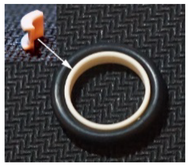
Figure 1 shows the schematic diagram of the piston rod seal structure of a Stirling engine. At the top of the cover plate is the piston cold chamber, and the crankcase is below the bottom housing. Two sealing components are mounted in a series to prevent the working gas from entering into the crankcase from the cold chamber. The first sealing component is a seal sleeve that can move freely with the piston rod under the oil-lubricated condition. The second sealing component is the Cap-seal (Figure 2), which consists of an O-ring and a C-ring under oil-free lubrication conditions. A backing ring is arranged under the Cap-seal to scrape off the attached lubricating oil on the piston rod in order to prevent damage to the working gas. The piston and piston head are interference fit and the piston rod and piston head are threaded. The piston rod is in clearance fit with the upper shell, the lower shell and the cover plate. The linkage is connected with the crankshaft, piston rod and slide block. The slide block is clearance fit with the cylinder barrel.
The movement of the piston is realized by the crank slider mechanism, so it produces a periodic radial offset motion while reciprocating, as shown in Figure 3. Firstly, as shown in Figure 3a,b, the piston rod is collinear with the linkage without deflection when the piston is at TDC (top dead center) and BDC (bottom dead center). Secondly, as shown in Figure 3c,d, during the reciprocating motion of the piston, the piston rod and linkage produce an offset due to the rotation of the crankshaft, and the deflection directions of the piston rod and linkage are opposite to one another under the action of the crosshead.
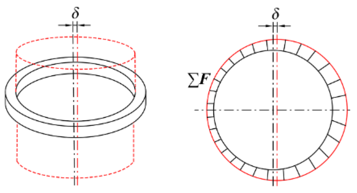
A parallel offset of the piston rod would changes the radial compression, thus increasing the possibility of deformation, resulting in irregular contact pressure distributed by the cover seal, and affecting the sealing performance. Figure 4 represents the radial contact pressure distribution of the Cap-seal when the piston rod is in the offset position. The offset results in a change of clearance δ between the piston shaft and the seal, and the clearance δ varies with different swing angles of linkage. δ reaches its maximum when the angle between the linkage and the crankshaft is at the maximum and its minimum when the piston reaches TDC or BDC. Moreover, an offset of the piston rod tends to twist the seal into the groove, thus affecting the axial stress distribution of the seal. Due to the elastic compensation ability of the O-ring, the Cap-seal is quite resistant to overturns and the axial force distribution is uniform.

3. Material and Method

3.1. Material Model

The material of the C-ring was nano-ZrO2-filled polytetrafluoroethylene, with a Young’s modulus of 900 MPa and Poisson ratio of 0.4. The details of its parameters can be found in Ref. [26]. The material used for the O-ring was nitrile rubber, and according to Rivlin’s phenomenological theory of rubber elasticity, a rubber material can be modeled as an isotropic and incompressible hyperelastic material. Taking into account the nonlinear properties of rubber materials, the two-constant Mooney–Rivlin formulation was selected to describe the mechanical characteristics of the O-ring [27], as shown below:
W = C 10 ( I 1 3 ) + C 01 ( I 2 3 )
where W is the strain energy function, and I 1 and I 2 are the first and second stress invariants, respectively. According to Ref. [6], C 10 = 1.87 MPa and C 01 = 0.47 MPa.

3.2. Parallel-Offset Analysis

The axis of the piston rod intersects the axis of the crankshaft vertically. When the piston crosses the TDC or BDC, the direction of the lateral force in the piston changes, causing parallel offset in the piston rod. The piston rod is tightly combined with the C-ring under the action of the O-ring; thus, an offset of the piston rod was assumed to occur only on the horizontal plane of the seal. Taking advantage of its symmetry, when parallel offset of the piston rod occurs, one side of the seal is re-compressed and the other side is released, similar to that in the work by Pinedo et al. [4,5] and Peng et al. [28]. Under the offset motion, the clearance between the piston and cylinder changes. In this paper, the clearance δ value was set to 0.1 mm.

3.3. Wear Analysis

The structure of the Cap-seal, as shown in Figure 1, indicates that the surface of the C-ring in contact with the piston rod is the primary sealing surface. The sealing surface shows obvious wear under the oil-free lubrication condition. Wear of the C-ring is a dynamic process that is related to the contact pressure, sliding speed, ambient temperature, material properties, etc. Considering the relationship between wear and its influencing factors, the Archard wear model is one of the most commonly used theoretical calculation models [29]. In the Archard wear model, the wear is proportional to the normal pressure and sliding distance. Its formula is as follows:
V = K H F S
where V is the wear volume, K is a dimensionless wear coefficient, H is the surface hardness, F is the contact force, and S is the sliding distances.
Then, by dividing both sides of Equation (2) by the wear area Δ A , Equation (2) can be reformulated as follows:
h = k H P S
where h is the wear depth, and P is the local normal pressure in the wear area Δ A .
By defining the wear modulus as k = K / H , and using the time interval Δ t , Equation (3) can be reformulated as follows:
Δ h = k p t v Δ t
where Δ h is the increment of the wear depth, p t is the pressure change with time and v is the relative sliding velocity.
The C-ring and piston rod remained in contact during the operation of the Stirling engine. Because the steel rod has a higher wear resistance than the composite seal ring, only the wear of the C-ring was calculated and analyzed in this paper. The wear coefficient k needs to be obtained before the wear calculation, and the experimental method used in this paper is the optimal method for determining the wear coefficient. The wear coefficient values of nano-ZrO2-filled polytetrafluoroethylene used in this study were set between 4.2 × 10⁻⁶ mm3/Nm and 11.2 × 10⁻⁶ mm3/Nm, as shown in Ref. [26].

3.4. Numerical Model

A geometric model of the Cap-seal sealing component was created with the Solidworks® software. Figure 5 shows a sectional geometric model of the sealing structure. The C-ring length a is 3.6 mm; the width b of the top and bottom surfaces is 1.8 mm; the thickness c is 0.5 mm; the fillet radius R 0 is 0.3 mm; the inner diameter is the same as that of the piston shaft, 12 mm; and the O-ring diameter d is 2.6 mm.
The geometric model was imported into the commercial finite element software Abaqus®, and a numerical analysis of the material, contact, and wear was performed using commercial code. Since the Cap-seal has an uneven radial force when the piston rod is offset, a tridimensional model was built to estimate the sealing performance. The piston rod, upper housing, and backing ring were modeled as a rigid body. The Cap-seal was modeled as a deformable body in which C3D8 was used for meshing the C-ring and C3D8H was used for meshing the O-ring. An illustration of the meshed model is shown in Figure 6.
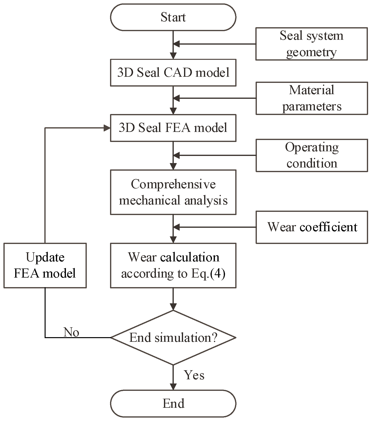
In the finite element method (FEM), four surface-to-surface contact pairs were established, which were between the O-ring and the C-ring, between the C-ring and the piston rod, between the C-ring and the backing ring, and between the O-ring and the upper housing. The soft material surface was set as the slave surface, while the hard one was treated as the master surface. In the interactions, the tangential behavior was defined using penalty algorithms with a value of 0.2 for the coefficient of friction between rubber and steel [13]. The wear of the seal was determined using Fortran®-Subroutine “Umeshmotion”, which can be used to move mesh nodes independent of the underlying material in an adaptive mesh region [3]. The contact surface between the C-ring and the piston rod was defined as the wear surface, and the nodal contact pressure was calculated when the simulation started. Then, the wear depth for a user-defined number of time increments with the nodal contact pressure was calculated according to Equation (4) and the upper C-ring geometry was updated using the ale-adaptive mesh constraint method. Finally, the wear depth at a specific time was obtained using the cycling solution. In the numerical analysis, wear was viewed as a quasi-static process [30]. A chart of the simulation’s routine is shown in Figure 7.
The simulation procedure can be divided into the following four steps:
Step 1. Pre-compression analysis. An initial displacement in the vertical direction is exerted on the upper housing and backing ring to allow it to move upward, while the fixed boundary conditions are applied to the C-ring as shown in Figure 8a.
Step 2. Pressurization analysis. The gas pressure is applied to the upper side of the Cap-seal to simulate the action of gas pressure, as shown in Figure 8b.
Step 3. Offset analysis. The piston rod (and backing ring) is displaced upward in the selected radial misalignment direction as shown in Figure 8c.
Step 4. Wear analysis. The piston rod moves up and down, and the wear depth of the contact surface between the C-ring and the piston rod within the selected time is determined, as shown in Figure 8d. Then, the C-ring model is updated according to the amount of wear, and the previous step is performed again.

4. Experimental Measurements

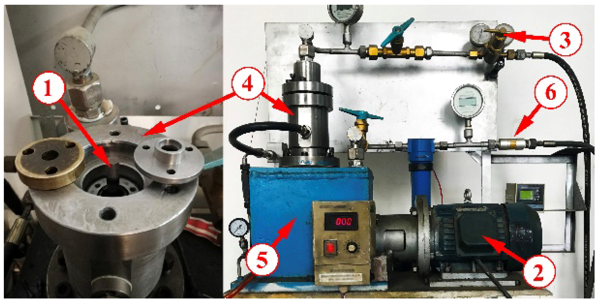
A suitable test device was designed and assembled to simulate the actual working conditions, as shown in Figure 9. The piston rod (1) was driven by the electric motor (2), with the speed ranging from 0 to 5000 r/min. Prior to the test, the piston crown cavity was filled with hydrogen. The gas pressure was controlled by the pressure gauge (3) and kept constant. The Cap-seal was mounted into the test chamber (4). During the test, hydrogen leaking from the seal can cause the pressure buildup in the crankcase (5) to rise, thereby triggering the stop valve (6) to open, and discharges it into the environment. After the test, the C-ring surface profile was measured using a 3D surface profiler (NanoMap®-500LS).

5. Results and Discussion

5.1. Initial State

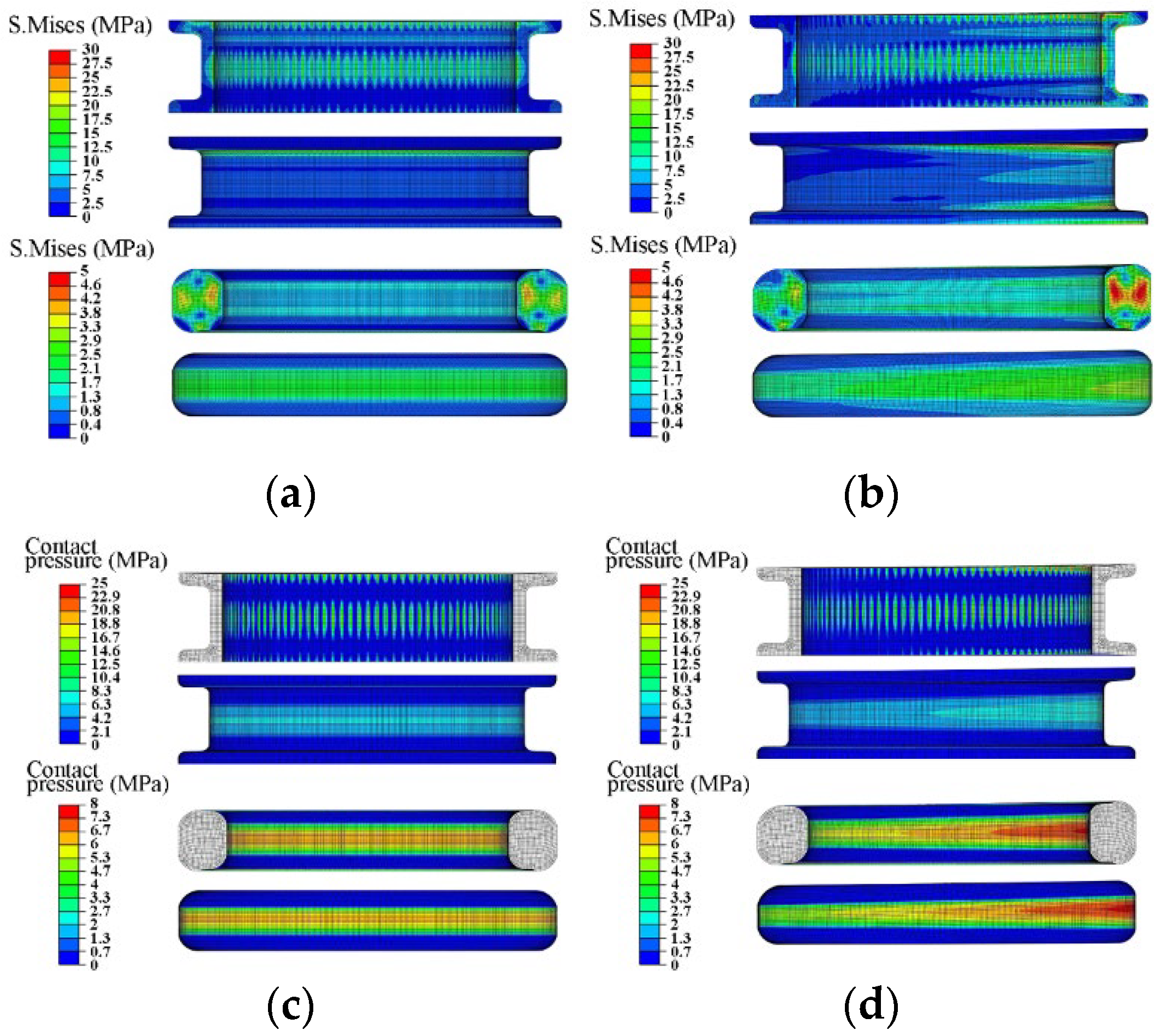
Seals with efficient performances need to have uniform stress and sufficient contact pressure. Offsets of the piston rod lead to changes that affect the use of seals. Figure 10 shows a comparison of the stress and contact pressure distributions of Cap-seal under different initial conditions, for which the pre-compression rate was set to 15% and the gas pressure was set to 2 MPa. As illustrated in Figure 10a, the stress of the Cap-seal was distributed symmetrically along the axis in general. The maximum stress of the C-ring occurred on the inner side and at the top of the ring’s cross section. The shape of the stress distribution of the O-ring is a dumbbell. When the piston rod is offset, as shown in Figure 10b, the stress concentration area of the C-ring transfers to the offset side. Two high stress areas occur, located close to the top and bottom of the ring’s cross section. Additionally, the stress of the outer side is also higher than before, and the stress variation trend of the O-ring shows a similar trend to that of the C-ring. The possibility of a crack or elastic loss in an elastic seal increases with an increase in stress. Thus, an offset of the piston rod accelerates the damage to both the C-ring and the O-ring. As shown in Figure 10c,d, the O-ring makes closer contact with the C-ring and the outer surface of the upper housing on the offset side of the piston rod due to the offset motion. However, on the inner side of the C-ring, which is the primary sealing surface, the change in the contact state is not obvious.

5.2. Wearing Process

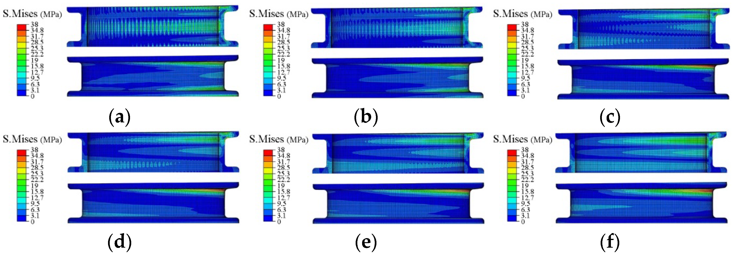
Two directions of movement occur when the piston rod reciprocates. One is defined as an outward stroke when in the same phase as the action direction of sealing pressure and the other is the inward stroke. Affected by friction, the seals exhibits different properties for the outward and inward strokes. Therefore, in the following analysis, the sealing performance of the outward stroke was used as a comparison. Figure 11 and Figure 12 show the stress distribution of the Cap-seal under different wear periods, where the pre-compression rate was set to 15% and the gas pressure was set to 2 MPa. As shown in Figure 11, the stress of the C-ring clearly changes with an increase in the reciprocating distance of the piston rod, the stress concentration area in the middle of the inner side of the C-ring moves to the offset position and the value increases, the stress concentration area at the bottom of the inner side widens and increases, and the maximum stress on the outer side moves to the opposite direction from the offset position and changes slightly. As shown in Figure 12, the overall change in the stress distribution of the O-ring is not obvious, but that of its outer side increases slightly. According to the results, wear leads to a distortion and deformation of the lower part of the C-ring during operation, causing the seal to turn outward, resulting in seal failure.
Figure 13 and Figure 14 show the contact pressure distribution of the Cap-seal under different wear periods. As shown in Figure 13, with an increasing wear distance, the maximum contact pressure in the middle of the inner side of the C-ring decreases and moves to the offset position, while the distribution area becomes wider and the maximum contact pressure at the top of the inner side increases. As shown in Figure 14, the contact pressure of the O-ring changes insignificantly. Based on the analysis and contrast, although a higher contact pressure leads to increased wear, the contact stress on the offset of the seal is always higher than that on the other side during the wear process. This may be due to the good adaptability of the C-ring structure and the good compensation of the O-ring. Additionally, the results show that leakage is more likely to occur on the non-offset side because of the lower contact pressure.
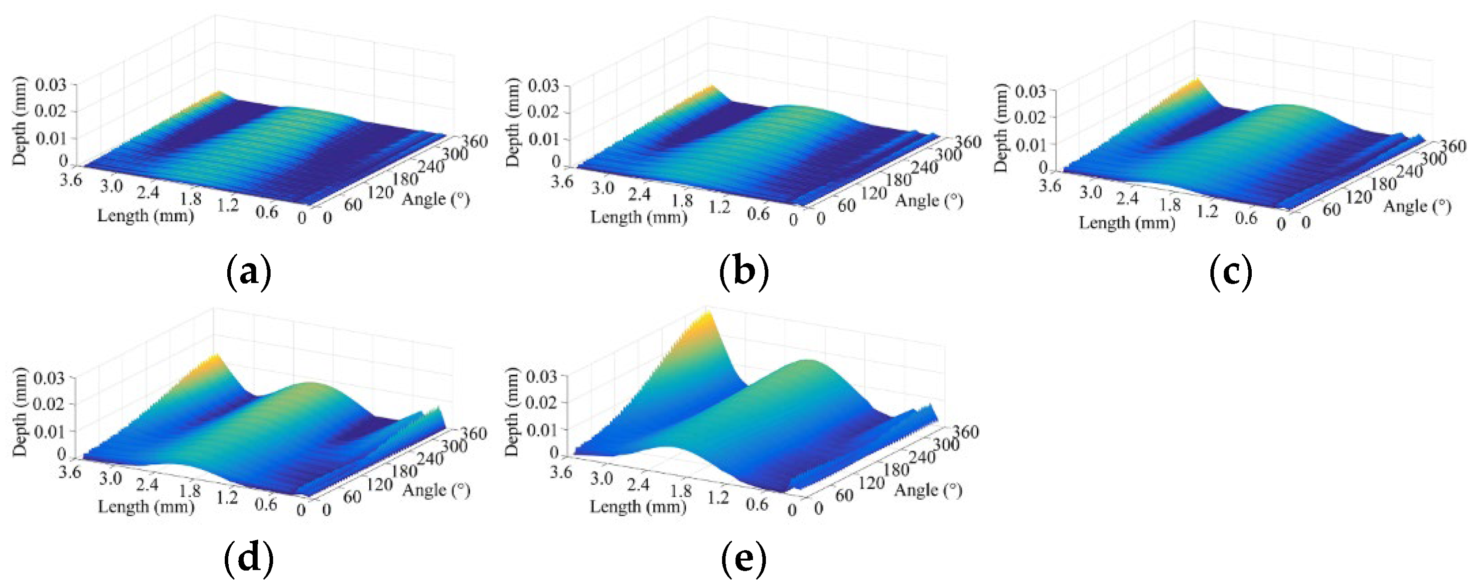
Figure 15 shows the calculated displacement of nodes on the inner side of the C-ring under different wear periods. The coordinates in the figure originate as points near the support ring on the other side of the offset. The node displacement curve of the inner surface of the C-ring is consistent with the results for contact pressure. At the initial stage, the contact pressure at the middle of the inner side of the C-ring is large, resulting in overall wear in the area. As the wear distance increases, the wear depth near the offset side increases compared with that on the other side. Additionally, in the later period, serious wear occurs at the top of the inner side and its maximum value is also greater. By comparing the wear curves of each stage, it can be seen that the rate of changes in the curves decreases because wear causes the contact area to widen, and the linear wear per unit sliding distance steadily decreases.
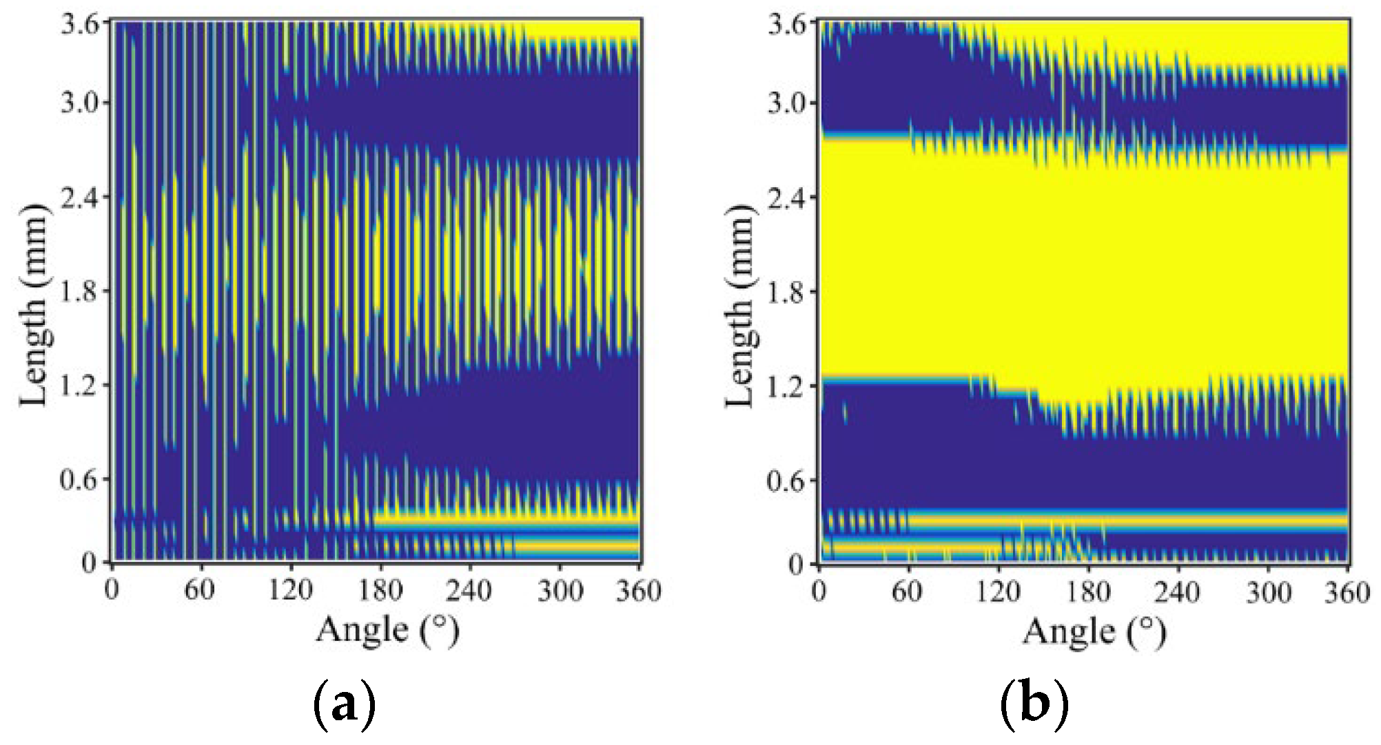
Figure 16 shows the contact state for the inner side surface of the C-ring; the yellow part of the figure indicates the presence of contact, which means that this area is an effective contact surface. As shown in Figure 16a, at the initial stage, from the offset side to the other side, the width of the axial contact in the middle of the sealing surface increases and the circumferential contact width decreases. In this case, the contact surface shows poor continuity. As shown in Figure 16b, after a period of wear, a wide and uniform contact zone is formed in the middle of the sealing surface and the top contact zone also continues to expand. Through the analysis of the results, it was found that an offset in the piston rod had little effect on the leakage, and this effect was more obvious with an increase in the wear of the sealing surface. From the above results, it can be concluded that an offset in the piston rod can aggravate the wear of the seal surface on this side, thus increasing the probability of sealing damage under greater stress. However, the influence of an offset on the sealing ability is not obvious, and leakage is more likely to occur on the opposite side.

5.3. Effects of the Working Conditions

Under the action of different gas pressures and pre-compression rates, the deformation and stress state of the Cap-seal are different and the wear condition is affected differently. Figure 17 shows the maximum contact pressure, the maximum mises stress, the wear volume, and effective contact surface rate of the C-ring under a gas pressure of 5 MPa and of 2 MPa. The compression rate was set to 15%. As shown in Figure 17a, the increased gas pressure increases the contact pressure at the initial stage and increases the range for a drop in pressure during wear, and this change is more obvious on the offset side. It also can be seen that when the gas pressure is 5 MPa, the stress of the C-ring increases significantly during operation, which shows an increased risk of seal damage. As shown in Figure 17b, the wear volume of the C-ring is large when the gas pressure is 5 MPa, but with an increase in wear distance, the decrease in contact pressure inhibits the continuously increasing trend for wear on the sealing surface. During the wear process, the effective surface contact rate of the C-ring continues to increase under 2 MPa but decreases significantly in the middle and late stages under 5 MPa. This phenomenon is consistent with the changes in the contact pressure and wear volume of the C-ring, indicating that seal leakage occurs in this case.
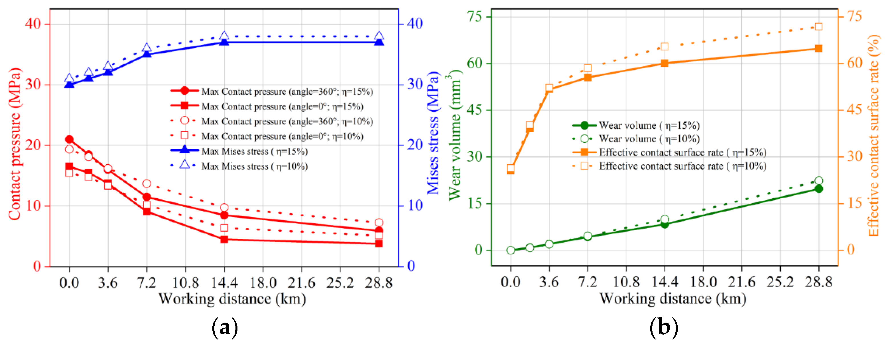
Appropriate pre-compression is affected by the stable and reliable self-sealing of the Cap-seal. Therefore, with a sealing performance of under 10%, the pre-compression ratio is further studied with the gas pressure set to 2 MPa. As shown in Figure 18a, on the offset side and its opposite side, the maximum contact pressure of the C-ring under a 10% compression rate is lower under the initial wear, but the decreasing amplitude decreases with the progression of wear, so it is higher in the later stage. By contrast, the maximum mises stress increases with the pre-compression rate. As shown in Figure 18b, although the wear of the C-ring at a 10% pre-compression rate is high for all stages of wear, its effective contact surface rate is also higher. Such a result suggests that the Cap-seal may have a better sealing capacity at low pre-compression ratios and exhibits a higher propensity for mechanical damage at the same time.

5.4. Experimental

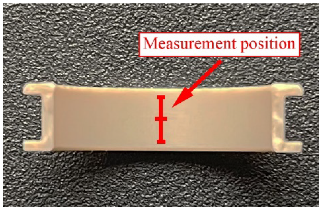
A sealing test was carried out on the test device, with the pressure of the working medium set as 2 MPa and the running distance set as 14.4 km. After each test, the axial profile of the offset side and the opposite side on the inner surface of the C-ring was measured. The original point of measurement was established at the center of inner surface, and 1.5 mm from the left and right was measured, as shown in Figure 19. As shown in Figure 20, the wear depth on the offset side is greater than that on the other side and the maximum wear position shifts to the middle of the inner surface. In addition, the wear is deep during actual operation, as seen by comparing the simulation results presented in Figure 15. This result may be caused by the fact that, during actual operation, the seal deforms along the axial direction when the piston rod is offset to increase the contact pressure on the sealing surface and to aggravate the wear. By comparing the variation characteristics of the numerical simulation and the experimental curves, it can be seen that, although there are some errors between them, but the overall degree of coincidence is good, which proves the reliability of the finite element method.

6. Conclusions

In this paper, a three-dimensional finite element model was built to investigate the effects of piston rod parallel offset on the wear performance of oil-free seals. The influence of working conditions on the sealing performance was studied and a sealing test was carried out. The method and results obtained can offer guidelines regarding the design and application of oil-free lubrication seals for a Stirling piston rod and provide an effective solution for solving other sealing problems. The following conclusions were drawn:
  • The offset of the piston rod will aggravate wear, which increases the possibility of seal damage under greater stress.
  • The contact pressure is not obviously affected by the seal wear when the piston rod is offset, and the opposite side of the offset is more prone to leakage.
  • Cap-seal shows good a sealing capability under high pressures and low pre-compression ratios, but it exhibits a higher propensity for mechanical damage.
  • The result of the wear test is in good agreement with that of the numerical simulation, which verifies the correctness of the finite element analysis method.

Author Contributions

Conceptualization, W.C.; methodology, W.C.; software, W.C. and Z.C.; validation, Z.C., A.Z. and X.D.; formal analysis, X.D.; investigation, J.G.; resources, G.G.; data curation, G.G.; writing—original draft preparation, W.C.; writing—review and editing, W.C. and J.G.; funding acquisition, W.C., Z.C. and A.Z. All authors have read and agreed to the published version of the manuscript.

Funding

This research was funded by the Gansu Provincial Natural Science Foundation, grant number 21JR7RA334, grant number 21JR11RA066 and grant number 21JR1RA253; the Natural Science Foundation of Lanzhou Jiaotong University, grant number 2021015.

Institutional Review Board Statement

Not applicable.

Informed Consent Statement

Not applicable.

Data Availability Statement

Not applicable.

Conflicts of Interest

The funders had no role in the design of the study; in the collection, analyses, or interpretation of data; in the writing of the manuscript, or in the decision to publish the results.

References

  1. Smith, P.J.; Keith JR, T.J. Simulation of an oil-pumping ring seal for a Stirling engine. Simulation 1980, 35, 49–60. [Google Scholar] [CrossRef]
  2. Mao, J.; Wang, W.; Liu, Y. Experimental and theoretical investigation on the sealing performance of the combined seals for reciprocating rod. J. Mech. Sci. Technol. 2012, 26, 1765–1772. [Google Scholar] [CrossRef]
  3. Frölich, D.; Magyar, B.; Sauer, B. A comprehensive model of wear, friction and contact temperature in radial shaft seals. Wear 2014, 311, 71–80. [Google Scholar] [CrossRef]
  4. Pinedo, B.; Aguirrebeitia, J.; Conte, M.; Igartua, A. Tri-dimensional eccentricity model of a rod lip seal. Tribol. Int. 2014, 78, 68–74. [Google Scholar] [CrossRef]
  5. Pinedo, B.; Conte, M.; Aguirrebeitia, J.; Igartua, A. Effect of misalignments on the tribological performance of elastomeric rod lip seals: Study methodology and case study. Tribol. Int. 2017, 116, 9–18. [Google Scholar] [CrossRef]
  6. Zhang, J.; Xie, J. Investigation of static and dynamic seal performances of a rubber O-ring. J. Tribol. 2018, 140, 042202. [Google Scholar] [CrossRef]
  7. Hu, G.; Wang, G.; Dai, L.; Zhang, P.; Li, M.; Fu, Y. Sealing failure analysis on V-shaped sealing rings of an inserted sealing tool used for multistage fracturing processes. Energies 2018, 11, 1432. [Google Scholar] [CrossRef] [Green Version]
  8. Belforte, G.; Conte, M.; Bertetto, A.M.; Mazza, L.; Raparelli, T.; Viscontea, C. Indirect contact pressure evaluation on pneumatic rod seals. Tribol. Int. 2018, 118, 240–245. [Google Scholar] [CrossRef]
  9. Gong, R.; Wang, H.; Zhang, H.; Xu, L. Influence of wear on hot banding migration of sealing ring using FEM. Wear 2019, 428, 449–456. [Google Scholar] [CrossRef]
  10. Yakovlev, N. An experimental study of the wear of the radial shaft seals of rotary shafts. J. Mach. Manuf. Reliab. 2019, 48, 179–183. [Google Scholar] [CrossRef]
  11. Zhou, C.; He, M.; Chen, G.; Jiang, S. Numerical study on sealing characteristic of rubber X-ring exposed to high-pressure hydrogen by considering swelling effect. Ind. Lubr. Tribol. 2019, 71, 133–138. [Google Scholar] [CrossRef]
  12. Azzi, A.; Maoui, A.; Fatu, A.; Fily, S.; Souchet, D. Experimental study of friction in pneumatic seals. Tribol. Int. 2019, 135, 432–443. [Google Scholar] [CrossRef]
  13. Zhang, Z.; Wu, D.; Pang, H.; Liu, U.; Wei, W.; Li, R. Extrusion-occlusion dynamic failure analysis of O-ring based on floating bush of water hydraulic pump. Eng. Fail. Anal. 2020, 109, 104358. [Google Scholar] [CrossRef]
  14. Sang, Y.; Wang, X.; Sun, W.; Liu, P. Numerical and experimental study on the friction of O ring for hydraulic seals. Aust. J. Mech. Eng. 2021, 19, 328–340. [Google Scholar] [CrossRef]
  15. Luo, H.; Wu, J.; Teng, F.; Su, B.; Li, H.; Lin, A.; Li, Z.; Wang, Y. Multiscale simulation on dynamic friction behavior of cylinder sealing rings under hydrothermal aging. J. Appl. Polym. Sci. 2021, 138, 50453. [Google Scholar] [CrossRef]
  16. Kaushal, N.; Patri, S.; Kumar, R.S.; Meikandamurthy, C.; Sreedhar, B.K.; Murugan, S.; Raghupathy, S. Characterising the dynamic seals used in absorber rod drive mechanisms in Indian FBR. Nucl. Eng. Technol. 2021, 53, 3438–3448. [Google Scholar] [CrossRef]
  17. Burris, D.L.; Boesl, B.; Bourne, G.R.; Sawyer, W.G. Polymeric nanocomposites for tribological applications. Macromol. Mater. Eng. 2007, 292, 387–402. [Google Scholar] [CrossRef]
  18. Scharf, T.W.; Prasad, S.V. Solid lubricants: A review. J. Mater. Sci. 2013, 48, 511–531. [Google Scholar] [CrossRef]
  19. Tadokoro, C.; Yoshii, Y.; Hattori, H.; Nishina, D. Friction and Wear Properties of PTFE Sliding Seals-Influence of Surface Conditions of Seal Gland on Friction Properties. Tribol. Online 2010, 5, 266–270. [Google Scholar] [CrossRef] [Green Version]
  20. Hu, Y.; Yan, W.; Wen, H.; Wen, C. Design and Analysis on a Kind of Oblique-Cone-Slid-Ring Assembly Seal Device with Self-Compensation to Seal Wear in Carbide Actor. Appl. Mech. Mater. 2011, 43, 247–252. [Google Scholar]
  21. Cao, W.; Gong, J.; Yang, D.; Gao, G.; Wang, H.; Ren, J.; Chen, S. Tribological behavior and energy dissipation characteristics of nano-Al2O3-reinforced PTFE-PPS composites in sliding system. J. Cent. South Univ. 2017, 24, 2001–2009. [Google Scholar] [CrossRef]
  22. Qi, Y.; Gong, J.; Cao, W.; Wang, H.; Ren, J.; Gao, G. Tribological behaviour of PTFE composites filled with PEEK and Nano-Al2O3. Tribol. Trans. 2018, 61, 694–704. [Google Scholar]
  23. Huang, R.; Ma, S.; Zhang, M.; Yang, J.; Wang, D.; Zhang, L.; Xu, J. Wear evolution of the glass fiber-reinforced PTFE under dry sliding and elevated temperature. Materials 2019, 12, 1082. [Google Scholar] [CrossRef] [PubMed] [Green Version]
  24. Gao, G.; Gong, J.; Qi, Y.; Ren, J.; Wang, H.; Yang, D.; Chen, S. Tribological behavior of PTFE composites filled with PEEK and nano-ZrO2. Tribol. Trans. 2020, 63, 296–304. [Google Scholar] [CrossRef]
  25. Shen, M.; Li, B.; Zhang, Z.; Zhao, L.; Xiong, G. Abrasive wear behavior of PTFE for seal applications under abrasive-atmosphere sliding condition. Friction 2020, 8, 755–767. [Google Scholar] [CrossRef] [Green Version]
  26. Cao, W.; Gong, J.; Qi, Y.; Yang, D.; Gao, G.; Wang, H.; Ren, J.; Chen, S. Tribological Behavior of Nano-ZrO2 Reinforced PTFE-PPS Composites. J. Wuhan Univ. Technol. 2019, 34, 527–533. [Google Scholar] [CrossRef]
  27. Yeoh, O.H. Some forms of the strain energy function for rubber. Rubber Chem. Technol. 1993, 66, 754–771. [Google Scholar] [CrossRef]
  28. Peng, C.; Guo, S.; Ouyang, X.; Yang, H. An eccentric 3-D fluid-structure interaction model for investigating the effects of rod parallel offset on reciprocating-seal performance. Tribol. Int. 2018, 128, 279–290. [Google Scholar] [CrossRef]
  29. Sui, H.; Pohl, H.; Schomburg, U.; Upper, G.; Heine, S. Wear and friction of PTFE seals. Wear 1999, 224, 175–182. [Google Scholar] [CrossRef]
  30. Söderberg, A.; Andersson, S. Simulation of wear and contact pressure distribution at the pad-to-rotor interface in a disc brake using general purpose finite element analysis software. Wear 2009, 267, 2243–2251. [Google Scholar] [CrossRef]
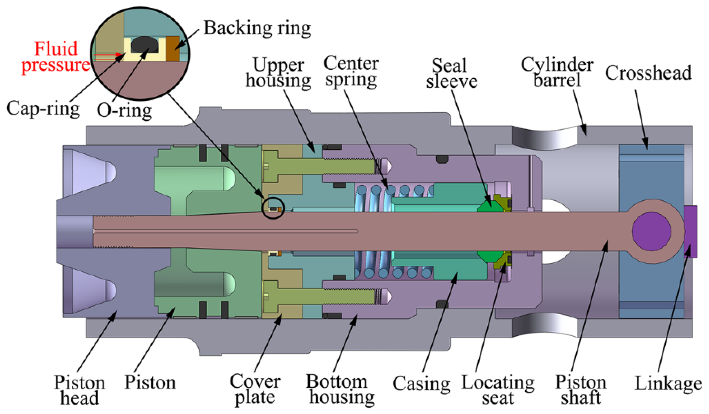
Figure 1. Schematic diagram of piston rod seal structure of Stirling engine.
Machines 10 00350 g001
Figure 2. Photograph of Cap-seal.
Machines 10 00350 g002
Figure 3. Parallel offset motion of piston rod under reciprocating. (a) TDC; (b) BDC; (c,d) Parallel offset motion.
Machines 10 00350 g003
Figure 4. Contact pressure distribution of Cap-seal.
Machines 10 00350 g004
Figure 5. Schematic of the Cap-seal.
Machines 10 00350 g005
Figure 6. Finite element meshed model.
Machines 10 00350 g006
Figure 7. The simulation routine.
Machines 10 00350 g007
Figure 8. Analysis steps of the Cap-seal. (a) Pre-compression; (b) Pressurization; (c) Offset; (d) Wear.
Machines 10 00350 g008
Figure 9. Experimental setup of the test system.
Machines 10 00350 g009
Figure 10. Stress and contact pressure distributions of Cap-seal under initial conditions. (a,c) δ = 0 mm; (b,d) δ = 0.1 mm.
Machines 10 00350 g010
Figure 11. Stress distribution of C-ring under different working distances. (a) 0 km; (b) 1.8 km; (c) 3.6 km; (d) 7.2 km; (e) 14.4 km; (f) 28.8 km.
Machines 10 00350 g011
Figure 12. Stress distribution of O-ring under different working distances. (a) 0 km; (b) 7.2 km; (c) 28.8 km.
Machines 10 00350 g012
Figure 13. Contact pressure distribution of C-ring under different working distances. (a) 0 km; (b) 1.8 km; (c) 3.6 km; (d) 7.2 km; (e) 14.4 km; (f) 28.8 km.
Machines 10 00350 g013
Figure 14. Contact pressure distribution of O-ring under different working distances. (a) 0 km; (b) 7.2 km; (c) 28.8 km.
Machines 10 00350 g014
Figure 15. Calculated displacement of nodes at the inner side of C-ring under different working distances. (a) 1.8 km; (b) 3.6 km; (c) 7.2 km; (d) 14.4 km; (e) 28.8 km.
Machines 10 00350 g015
Figure 16. Inner side surface contact state of C-ring under different working distances. (a) 0 km; (b) 14.4 km.
Machines 10 00350 g016
Figure 17. (a) Maximum contact pressure and maximum mises stress; (b) Wear volume and effective contact surface rate of C-ring under different gas pressure.
Machines 10 00350 g017
Figure 18. (a) Maximum contact pressure and maximum mises stress; (b) Wear volume and effective contact surface rate of C-ring under different pre-compression rate.
Machines 10 00350 g018
Figure 19. Measurement position of c-ring inner surface profile.
Machines 10 00350 g019
Figure 20. Inner surface axial profile curve of C-ring after 14.4 km working distance. (a) Opposite side to offset; (b) Offset side.
Machines 10 00350 g020
Publisher’s Note: MDPI stays neutral with regard to jurisdictional claims in published maps and institutional affiliations.