Dynamic Modeling and Stability Analysis for a Spur Gear System Considering Gear Backlash and Bearing Clearance

Abstract
:1. Introduction
2. Meshing Model of a Spur Gear Pair with Gear Backlash and Bearing Clearance
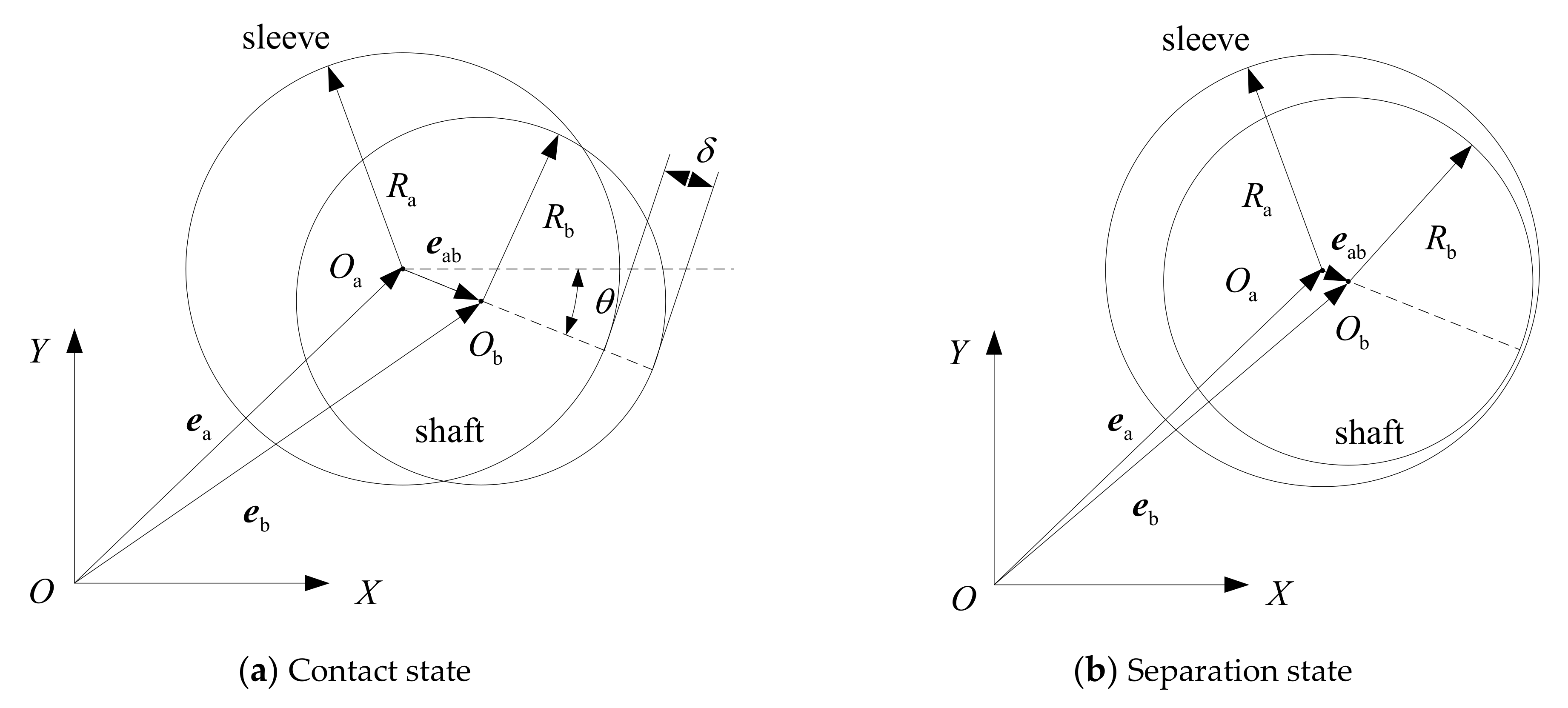
2.1. Nonlinear Bearing Collision Model Considering Bearing Clearance
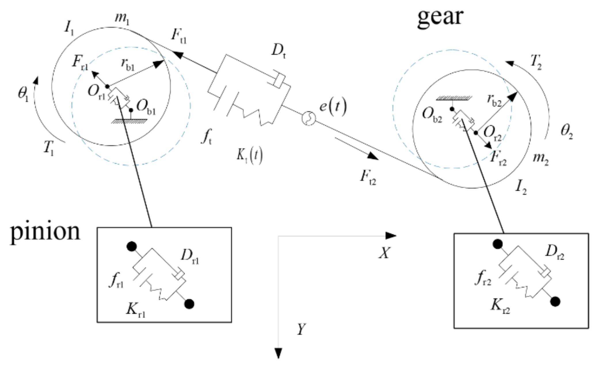
2.2. Coupling Motion Model of Gear Backlash and Bearing Clearance
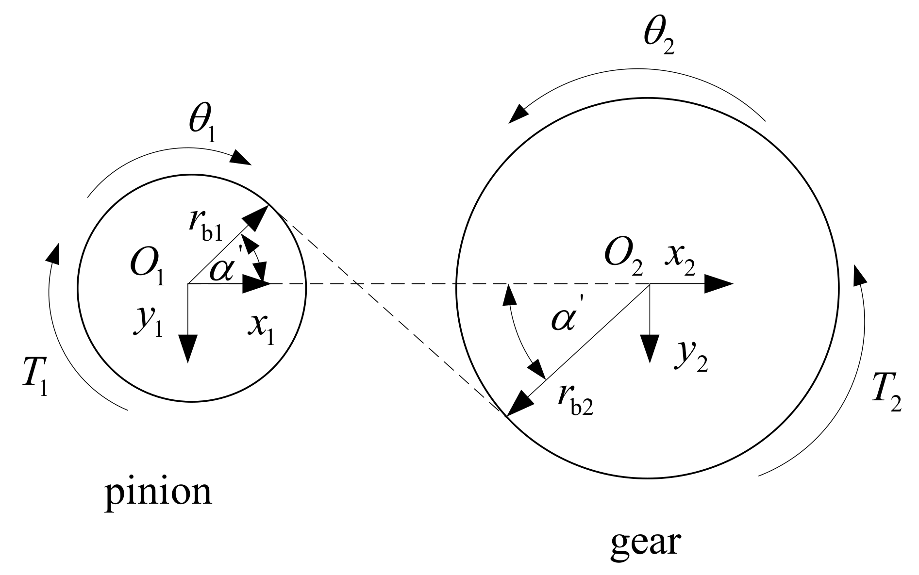
2.3. Meshing Force Model Considering Dynamic Backlash
2.4. Derivation of Equations of Motion
3. Comparison and Validation of Dynamic Models
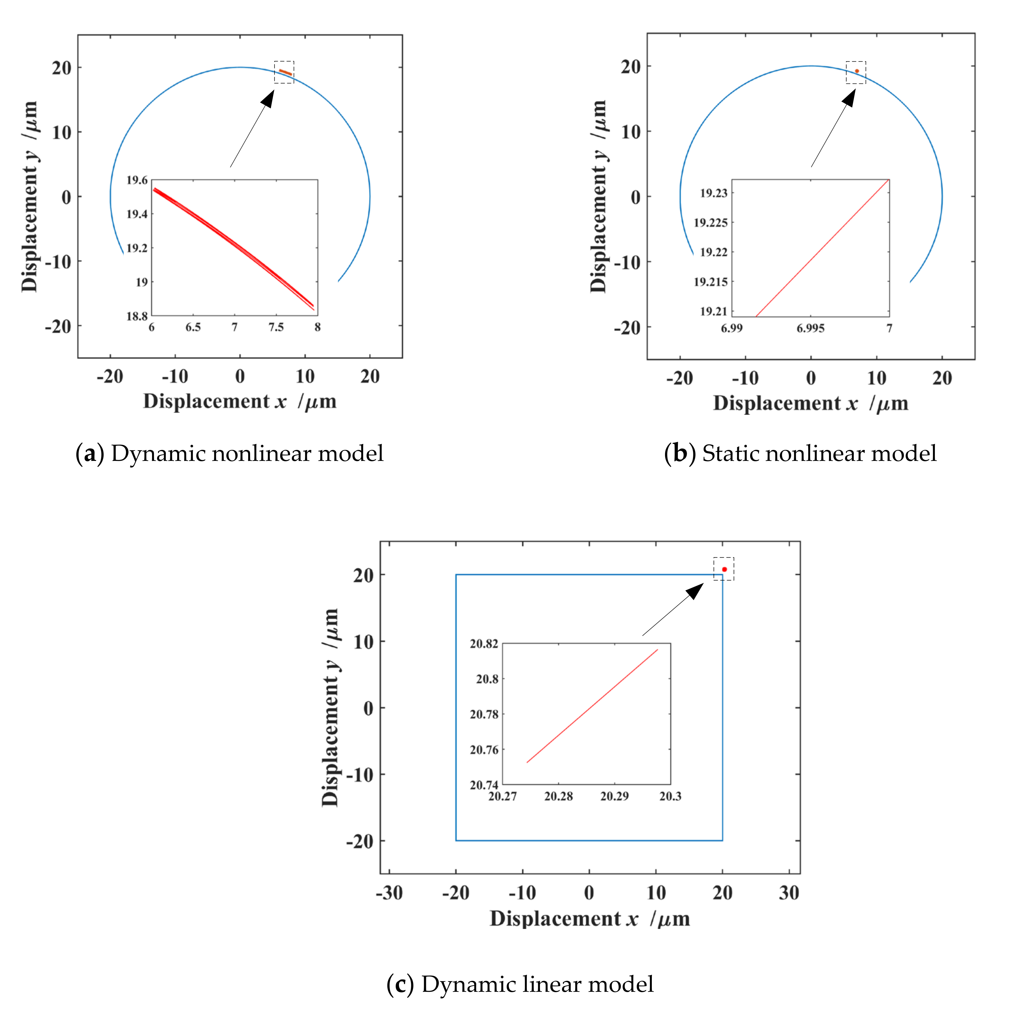
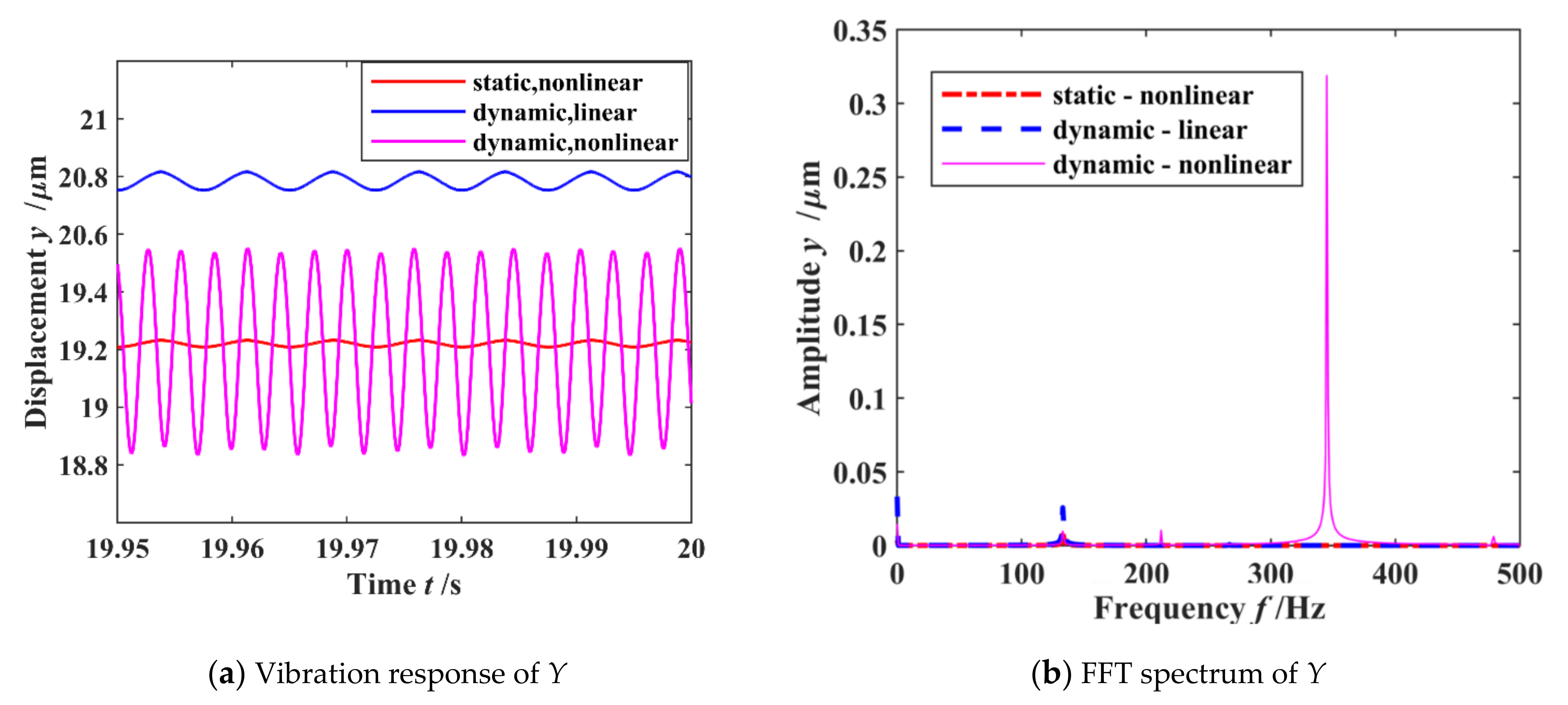
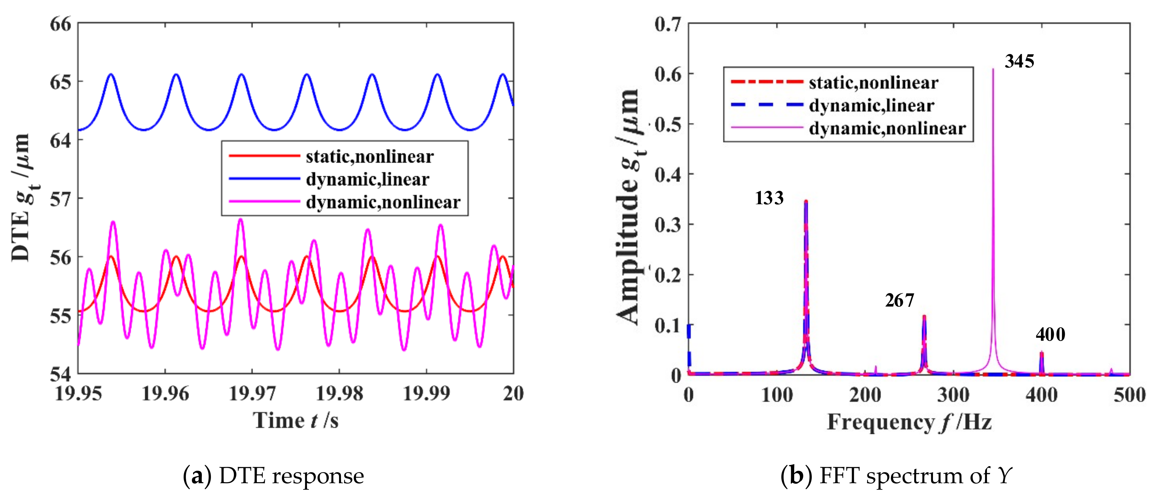
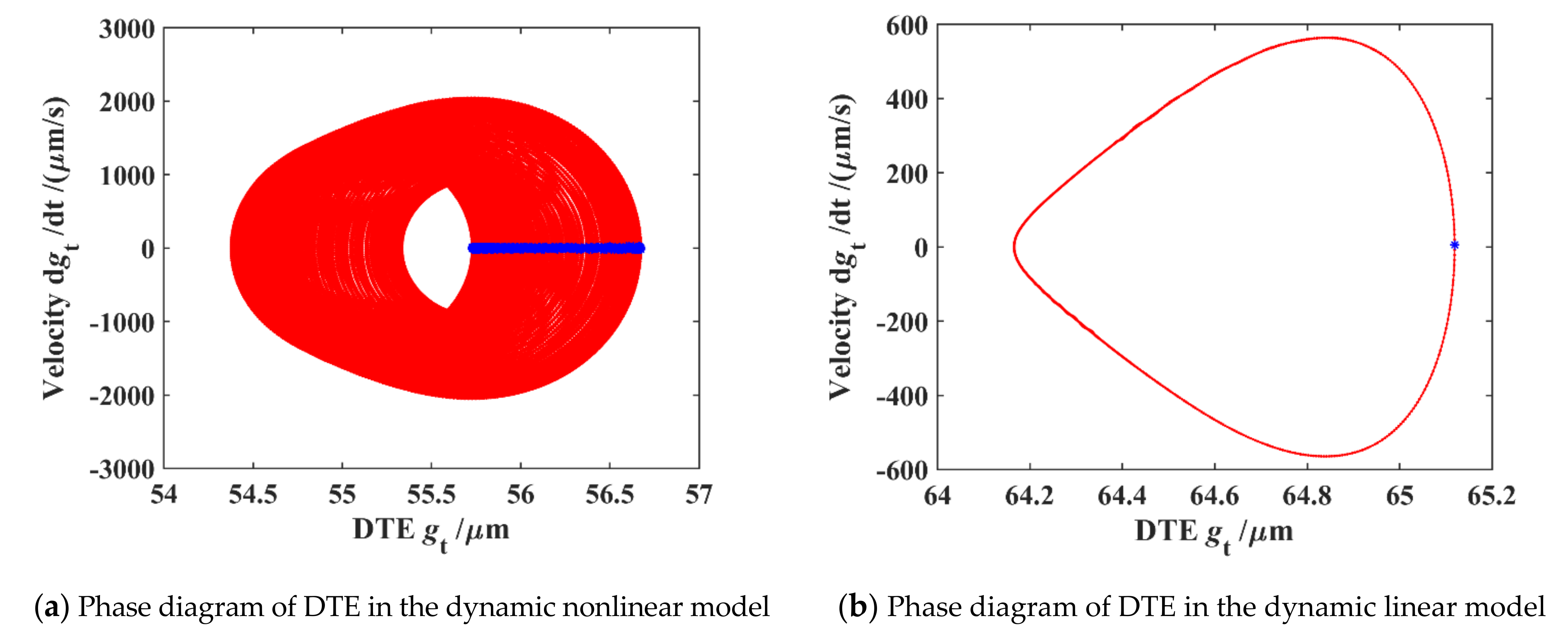
3.1. Model Comparison
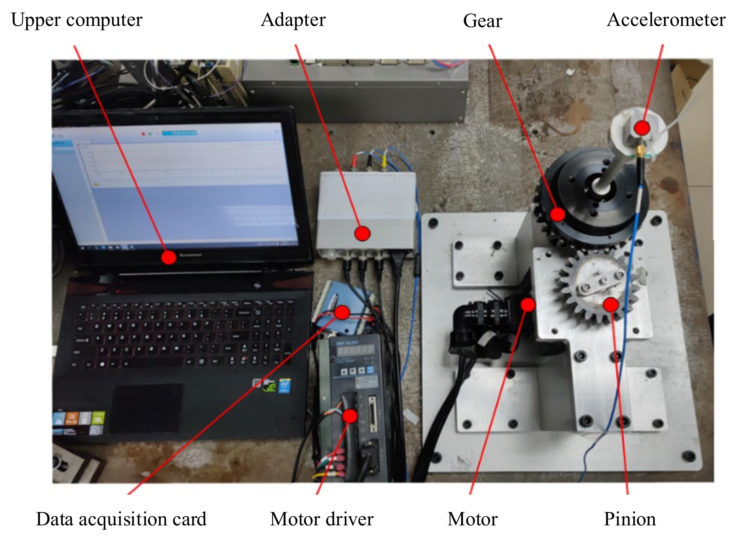
3.2. Model Validation
4. Stability Analysis
4.1. Effects of Rotational Speed of Pinion
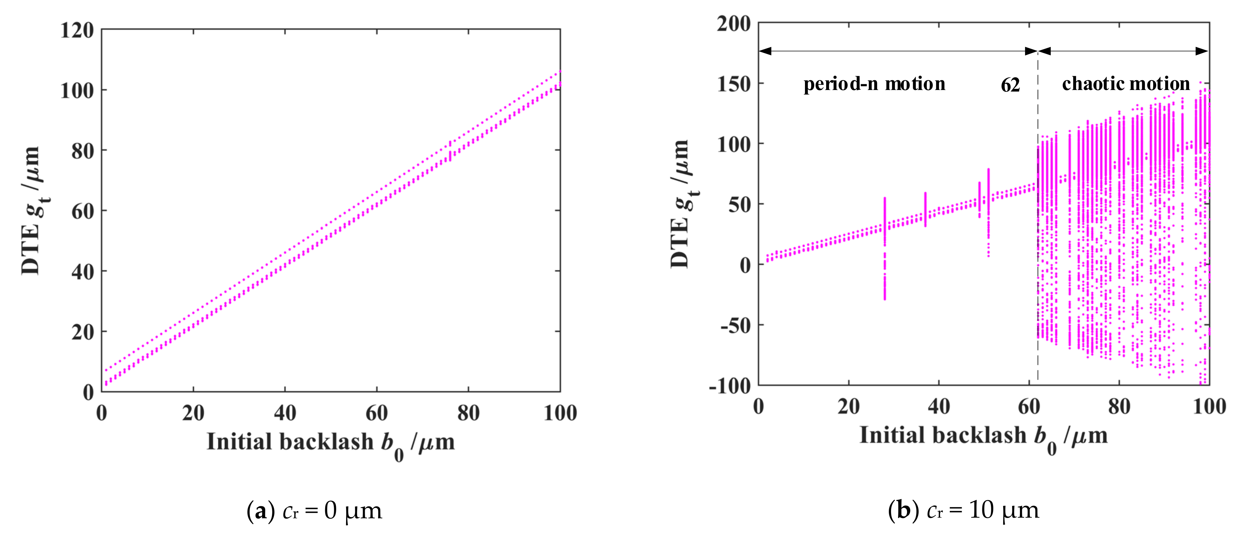
4.2. Coupling Effects of Initial Gear Backlash and Bearing Clearance
5. Conclusions
Author Contributions
Funding
Conflicts of Interest
References
- Velex, P.; Flamand, L. Dynamic Response of Planetary Trains to Mesh Parametric Excitations. J. Mech. Des. 1996, 118, 7–14. [Google Scholar] [CrossRef]
- Lin, J.; Parker, R.G. Planetary Gear Parametric Instability Caused by Mesh Stiffness Variation. J. Sound Vib. 2002, 249, 129–145. [Google Scholar] [CrossRef]
- Parker, R.G.; Wu, X. Parametric Instability of Planetary Gears Having Elastic Continuum Ring Gears. J. Vib. Acoust. 2012, 134, 41011. [Google Scholar] [CrossRef]
- Ligata, H.; Kahraman, A.; Singh, A. An experimental study of the influence of manufacturing errors on the planetary gear stresses and planet load sharing. J. Mech. Des. 2008, 130, 041701. [Google Scholar] [CrossRef]
- Vijayaraghavan, D.; Brewe, D.E. Effect of Misalignment on the Performance of Planetary Gear Journal Bearings; NASA Research Publication; NASA: Washington, DC, USA, 2005. [Google Scholar]
- Chaari, F.; Fakhfakh, T.; Hbaieb, R.; Louati, J.; Haddar, M. Influence of Manufacturing Errors on the Dynamic Behavior of Planetary Gears. Int. J. Adv. Manuf. Technol. 2006, 27, 738–746. [Google Scholar] [CrossRef]
- Gu, Y.K.; Li, W.F.; Zhang, J.; Qiu, G.Q. Effects of Wear, Backlash and Bearing Clearance on Dynamic Characteristics of a Spur Gear System. IEEE Access 2019, 7, 117639–117651. [Google Scholar] [CrossRef]
- Zhang, R.; Wang, K.; Shi, Y.; Sun, X.; Gu, F.; Wang, T. The Influences of Gradual Wears and Bearing Clearance of Gear Transmission on Dynamic Responses. Energies 2019, 12, 4731. [Google Scholar] [CrossRef] [Green Version]
- Kahraman, A.; Singh, R. Non-linear dynamics of a spur gear pair. J. Sound Vib. 1990, 142, 49–75. [Google Scholar] [CrossRef]
- Kahraman, A.; Blankenship, G.W. Experiments on Nonlinear Dynamic Behavior of an Oscillator with Clearance and Periodically Time-Varying Parameters. J. Appl. Mech. 1997, 64, 217–226. [Google Scholar] [CrossRef]
- Sun, T.; Hu, H.Y. Nonlinear dynamics of a planetary gear system with multiple clearances. Mech. Mach. Theory 2003, 38, 1371–1390. [Google Scholar] [CrossRef]
- Zhao, M.; Ji, J.C. Nonlinear torsional vibrations of a wind turbine gearbox. Appl. Math. Model. 2015, 39, 4928–4950. [Google Scholar] [CrossRef]
- Yang, T.; Yan, S.; Han, Z. Nonlinear model of space manipulator joint considering time-variant stiffness and backlash. J. Sound Vib. 2015, 341, 246–259. [Google Scholar] [CrossRef]
- Sheng, L.; Wu, Q.; Zhang, Z. Bifurcation and chaos analysis of multistage planetary gear train. Nonlinear Dyn. 2014, 75, 217–233. [Google Scholar]
- Guangjian, W.; Lin, C.; Li, Y.; Shuaidong, Z. Research on the dynamic transmission error of a spur gear pair with eccentricities by finite element method. Mech. Mach. Theory 2017, 109, 1–13. [Google Scholar] [CrossRef]
- Chen, Q.; Ma, Y.; Huang, S.; Zhai, H. Research on gears' dynamic performance influenced by gear backlash based on fractal theory. Appl. Surf. Sci. 2014, 313, 325–332. [Google Scholar] [CrossRef]
- Siyu, C.; Jinyuan, T.; Caiwang, L.; Qibo, W. Nonlinear dynamic characteristics of geared rotor bearing systems with dynamic backlash and friction. Mech. Mach. Theory 2011, 46, 466–478. [Google Scholar] [CrossRef]
- Yi, Y.; Huang, K.; Xiong, Y.; Sang, M. Nonlinear dynamic modelling and analysis for a spur gear system with time-varying pressure angle and gear backlash. Mech. Syst. Signal Process. 2019, 132, 18–34. [Google Scholar] [CrossRef]
- Liu, Z.; Liu, Z.; Zhao, J.; Zhang, G. Study on interactions between tooth backlash and journal bearing clearance nonlinearity in spur gear pair system. Mech. Mach. Theory 2017, 107, 229–245. [Google Scholar] [CrossRef]
- Kahraman, A.; Singh, R. Non-linear dynamics of a geared rotor-bearing system with multiple clearances. J. Sound Vib. 1991, 144, 469–506. [Google Scholar] [CrossRef]
- Huang, K.; Yi, Y.; Xiong, Y.; Cheng, Z.; Chen, H. Nonlinear dynamics analysis of high contact ratio gears system with multiple clearances. J. Braz. Soc. Mech. Sci. Eng. 2020, 42, 1–16. [Google Scholar] [CrossRef]
- Suzuki, A.; Aoyama, T.; Sugiura, N.; Inagaki, M.; Shimizu, T. Influence of Bearing Clearance on Load Sharing in Planetary Gears. In Proceedings of the ASME International Design Engineering Technical Conferences & Computers & Information in Engineering Conference, Washington, DC, USA, 28–31 August 2011. [Google Scholar]


| Parameter | Pinion | Gear |
|---|---|---|
| Number of teeth | 20 | 30 |
| Module (mm) | 4 | |
| Pressure angle (°) | 20 | |
| Face width (mm) | 20 | |
| Mass (kg) | 0.707 | 1.729 |
| Moment of inertia (kg·m2) | 5.65 × 10⁻⁴ | 1.64 × 10⁻³ |
| Material | steel | |
| Model | Parameter | Value | Error Percentage (%) |
|---|---|---|---|
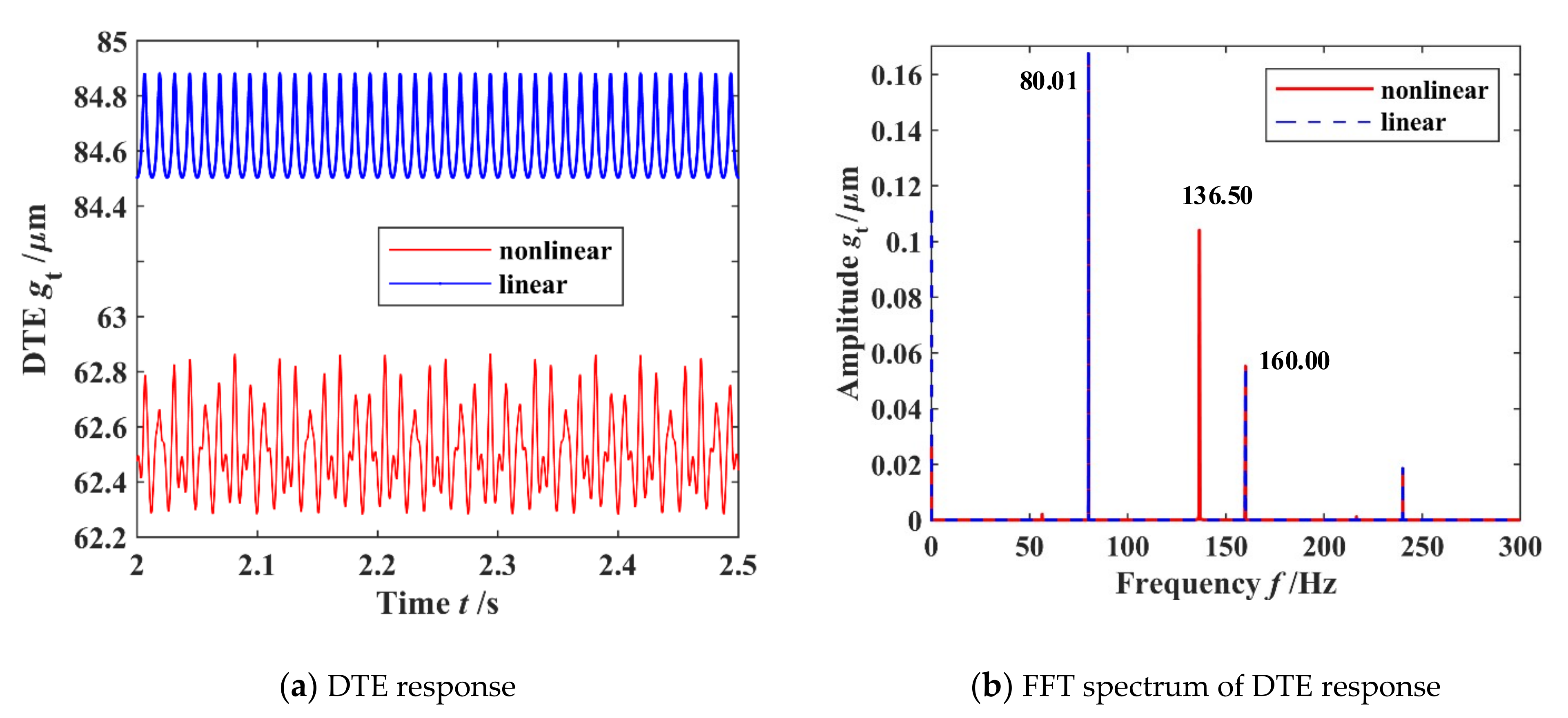
| Numerical simulation | Average of DTE | 62.62 μm | |
| 1 time meshing frequency | 80.01 Hz | ||
| 2 times meshing frequency | 160.00 Hz | ||
| Circular vibration frequency | 136.50 Hz | ||
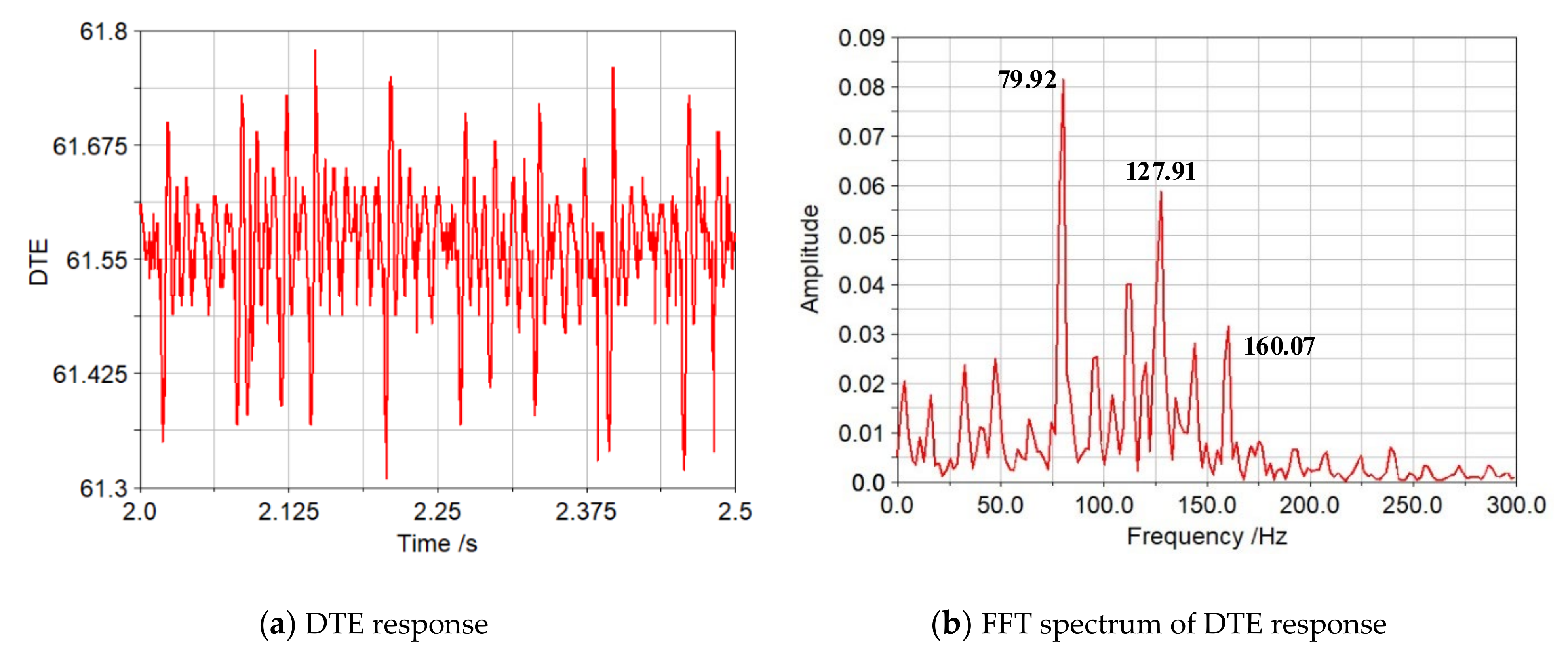
| virtual prototyping simulation | Average of DTE | 61.57 μm | 1.705 |
| 1 time meshing frequency | 79.92 Hz | 0.112 | |
| 2 times meshing frequency | 160.07 Hz | −0.044 | |
| Circular vibration frequency | 127.91 Hz | 6.716 | |
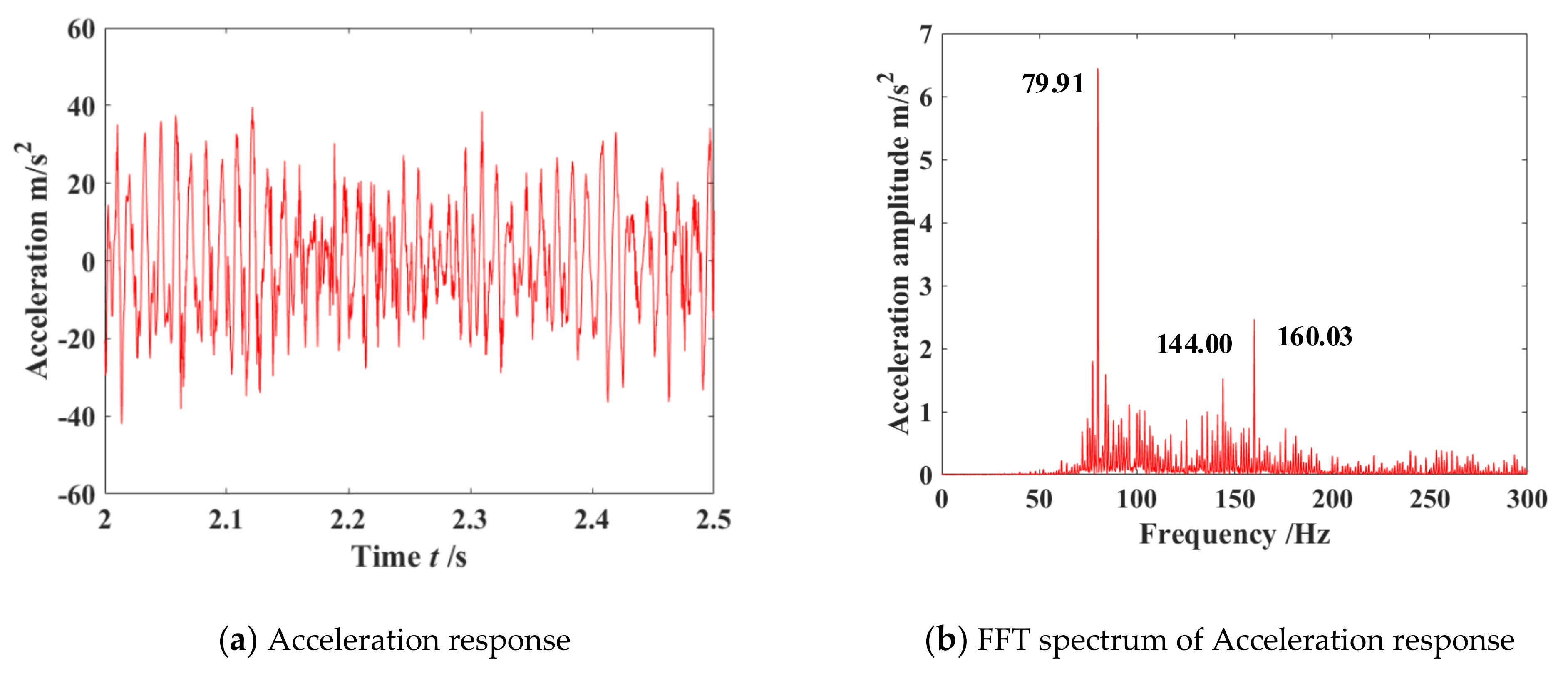
| physical experiment | 1 time meshing frequency | 79.91 Hz | 0.125 |
| 2 times meshing frequency | 160.03 Hz | −0.019 | |
| Circular vibration frequency | 144.00 Hz | −5.208 |
Publisher’s Note: MDPI stays neutral with regard to jurisdictional claims in published maps and institutional affiliations. |
© 2022 by the authors. Licensee MDPI, Basel, Switzerland. This article is an open access article distributed under the terms and conditions of the Creative Commons Attribution (CC BY) license (https://creativecommons.org/licenses/by/4.0/).
Share and Cite
Tian, G.; Gao, Z.; Liu, P.; Bian, Y. Dynamic Modeling and Stability Analysis for a Spur Gear System Considering Gear Backlash and Bearing Clearance. Machines 2022, 10, 439. https://doi.org/10.3390/machines10060439
Tian G, Gao Z, Liu P, Bian Y. Dynamic Modeling and Stability Analysis for a Spur Gear System Considering Gear Backlash and Bearing Clearance. Machines. 2022; 10(6):439. https://doi.org/10.3390/machines10060439
Chicago/Turabian StyleTian, Gang, Zhihui Gao, Peng Liu, and Yushu Bian. 2022. "Dynamic Modeling and Stability Analysis for a Spur Gear System Considering Gear Backlash and Bearing Clearance" Machines 10, no. 6: 439. https://doi.org/10.3390/machines10060439