Abstract
Feature extraction herein refers to using an appropriate wavelet basis to filter vibration signals with the aim to reveal fault transient characteristics, which underlies bearing fault diagnosis. Wavelet transform has developed into a well-established signal processing approach with wide applications in bearing fault diagnosis. Nevertheless, a suitable wavelet basis is essential for wavelet transform to perform its best. So far, numerous wavelet bases are available for bearing diagnosis, most of which, however, have a waveform analogous to that of impulse responses of a single-degree-of-freedom system. In fact, bearings are of multi-degree-of-freedom and not totally rigid. Furthermore, a specific wavelet basis is definitely unable to accommodate all bearing vibrations, given that fault characteristics vary with bearings’ operating conditions and fault types. As such, a simulated wavelet-driven personalized scheme is proposed to improve bearing fault diagnosis for contextualized engineering practical applications. For a specific bearing of interest, personalized finite element models (FEM) with various faults are constructed and corresponding fault-induced responses are then obtained. Afterward, FEM-based wavelet bases are formulated and specified by its discrete values from such responses. Taking NU306 bearing with inner or outer defect for example, FEM-based wavelet basis is applied to the corresponding experimental signals by means of wavelet filtering. The comparisons with adaptive Morlet and impulse wavelet demonstrate that the personalized FEM-based wavelet basis match very well with the fault-induced transients present in experimental bearing vibrations and thus have a promising superiority and expandability.
1. Introduction
Rolling element bearings play a paramount role in the industry, transportation, aerospace, and other fields, where bearings are mainly employed to carry the radical dynamic loads of rotating shafts [1,2,3]. Rolling bearings are extremely prone to damage due to their harsh working conditions [4,5]. The influence of bearing failures on mechanical equipment could be disastrous, which may cause not only severe economic loss but operators’ casualties [6]. Therefore, the accurate determination of the health status of rolling bearings is crucial to improving the reliability and validity of mechanical systems. Nevertheless, it is not straightforward to achieve an accurate fault diagnosis of bearings since the fault characteristics are faint due to the transmission paths, background noise, and other interference factors [7,8,9].
Vibration signals contain rich information about the health status of machinery, and the fault diagnosis schemes based on vibration signal processing have evolved rapidly with tremendous achievements [10,11,12], such as empirical wavelet transform (EWT) [13,14], an improved version of tunable Q-factor wavelet transform (TQWT) [15], and maximum correlated kurtosis deconvolution (MCKD) method based on correlated kurtosis (CK) [16,17,18,19].
Wavelets are considered perfect tools for fault feature extraction due to their flexibility and computational efficiency. For wavelet filtering, the similarity between the wavelet basis and the fault characteristics embedded in vibration signals plays a decisive role in its success. So far, many efforts have been devoted to producing a wavelet basis that matches as closely as possible the fault-induced impulse response of bearings. Due to the fact that the Morlet wavelet and impulse response wavelet have good properties of multi-resolution analysis and time-frequency localization, they are widely employed in wavelet transform. Qin et al. [20] proposed a weak transient fault feature extraction method utilizing the Morlet wavelet optimized by kurtosis maximization. Liu et al. [21] used the Morlet wavelet correlation filtering to enhance transient features of gear faults, and the results verified its advantages in practical diagnostic applications. He et al. [22] applied the impulse response function correlation filtering to select the matching basis to overcome the restriction imposed by a low Signal-to-Noise Ratio (SNR). The aforementioned works adjust wavelet bases by changing their parameters, but resulting in only a trivial variation in the waveform of basis function and thus an unsatisfied matching with the fault-induced impact characteristics.
To deal with this dilemma, Li et al. [23] used the hammering approach to produce the impact response of a rotatory machine in the case of its static state, where the measured impact response was directly adopted as the wavelet basis for consequent wavelet filtering. In view of the dynamics principle of mechanical systems, machinery presents personalized vibration behavior under different assembly and operating states [24]. Therefore, the wavelet basis obtained under the static state is not perfectly compatible with the actual fault-induced impacts.
Although achievements have been observed in arriving at a suited wavelet basis for fault feature extraction in the above-mentioned works, drawbacks remain to be tackled.
(1) The commonly used wavelet bases such as the Morlet and impulse response wavelet have a waveform similar to the impulse responses of a single-degree-of-freedom system, where only one natural frequency exists. As a matter of fact, mechanical components are not totally rigid and of multiple degrees-of-freedom, and thus with multiple natural frequencies [23]. Therefore, the above wavelet bases are difficult to make agree perfectly with actual fault impact responses.
(2) The parameters (such as central frequency and damping ratio) which govern the shapes of wavelet bases are iteratively optimized toward a satisfactory result. However, the influence of signal transmission path and an improper optimization index could lead to a considerable deviation of the obtained wavelet basis from the actual bearing fault impact response. Hence, new approaches that are free of parameter optimization deserve further investigation.
(3) Another drawback lies in the fact that the parameter optimization of the above wavelet bases is computationally intensive and time-costly, which is not readily applicable for online diagnosis. In the case of fault feature extraction by means of wavelet filtering, the essential step is to construct a wavelet basis that matches the impact response of bearing faults as perfectly as possible. The better the match, the better the fault feature extraction. Hence, there is an urgent need to find a technique that can automatically construct a well-matched wavelet basis resembling the actual bearing fault impact response.
Recently, with the advancement of finite element model (FEM) technology [25,26], it is possible to simulate the transient response of a defective bearing from which a FEM-based wavelet basis is possible to be formulated and specified by its discrete values at time moments. As an FEM-based wavelet comes from the FEM model of specific bearing-imposed corresponding constraints, bearing fault diagnosis based on such FEM-based wavelet bases is personalized and expected to be more precise than traditional wavelet bases. Personalized diagnosis by FEM simulation is increasingly being investigated [27,28]. Xiang et al. [29] introduced a personalized bearing diagnosis method, wherein bearing fault signals were augmented through the FEM technology, and the identification of bearing fault types was carried out with the aid of a wavelet packet transform and support vector machine (SVM). On this basis, Liu et al. [30] introduced cosine similarity into the establishment and modification of FEM models, which significantly improved the results of personalized bearing fault diagnosis.
To tackle the unsatisfied matching of existing wavelet bases with fault impulses, a personalized FEM-based wavelet is proposed for feature extraction. The vibration signal of a defective bearing is simulated firstly by its FEM model which is implemented within the framework of the fault mechanism and at the operating regime equivalent to the field bearing. Afterward, such simulated vibration is partitioned to result in an individual impact response which serves henceforward as a wavelet basis for extracting the fault features. It is notable that the main contributions of the present work are as follows:
(1) FEM divides a mechanical component of interest into multiple tiny and mutually coupled harmonic oscillators, the combination of the vibration vectors of which will leads to an infinite number of vibration modes, with one mode associating with one natural frequency. As such, a FEM-based simulated vibration of the component under investigation covers multiple oscillation frequencies, which is in an almost perfect line with the fact that a mechanical component is usually not a totally rigid body and is of multiple degrees-of-freedom. Therefore, the personalized FEM-based wavelet basis is expected to match much better with the actual bearing fault impact response than the commonly used wavelet basis with a single oscillation frequency such as Morlet and impulse response wavelet basis, and thus feature extraction is expected to be improved.
(2) The FEM-based wavelet bases are obtained directly from the FEM simulation of the mechanical components to be diagnosed, without an optimization process involving the signals collected from the physical counterpart of the components. As a consequence, the effect of the signal transmission path and incorrect identification of the parameters governing the wavelet basis on the finally determined wavelet basis could be avoided.
(3) The FEM-based wavelet bases are formulated in an offline manner in advance to be exploited in wavelet filtering for fault feature extraction, while an adaptive variant of the Morlet or impulse response wavelet basis is acquired online. It could thus be assumed that the FEM-based wavelet bases are adequate for an on-chip real-time diagnosis scheme.
(4) The proposed method can be contextualized for specific bearings in industrial equipment, thus yielding promising results with respect to improving diagnostic accuracy and increasing production efficiency. The remaining sections of this paper are arranged as follows. A brief introduction of FEM and transient feature extraction by wavelet filtering is presented in Section 2. Section 3 introduces the proposed personalized diagnosis based on FEM-based wavelet bases. The FEM simulations of the NU306 bearing are briefly described in Section 4, and the resultant simulated signals are also examined in this section. The results of the proposed method on experimental signals are shown in Section 5. Finally, Section 6 concludes the paper.
2. Theoretical Background
2.1. A Brief Review of the FEM Algorithm
As a commercial FEM software package, LS-DYNA provides a finite element approach to solve nonlinear dynamic problems of a variety of engineering applications including rolling bearings. Different from ANSYS, LS-DYNA is an explicit analysis program using the time central difference method. Denoting the initial displacement, velocity, and acceleration of a certain element at as , and respectively, with the solution span being divided equally into n parts with a step of , the purpose of the analysis program is to get the solutions , , and given that the ones at time 0, , , …, are known. The expression at moment is as follows:
where M, C, and K represent the mass matrix, damping matrix, and stiffness matrix of the system, respectively, while Qt donates the load vector that is applied to the system.
In the interval , the velocity can be approximated by the displacement as:
The relationship between acceleration and displacement is given by:
Substituting Equations (2) and (3) into Equation (1), the Equation (1) is rewritten as:
Equation (4) is the central difference method. It is observed from Equation (4) that if the and are known, can be calculated, and furthermore, the velocity and acceleration at moment can be estimated.
The stability term of the central difference method is as follows:
where is the minimum fixed vibration cycles, and represents the critical value.
2.2. Transient Feature Extraction by Wavelet Filtering
Localized faults occurring on rolling bearings are characterized by transient impulse responses. An adequate feature extraction allows the enhancement of transient impulses while reducing other irrelevant components like noise. Wavelet filtering has gained popular applications in transient feature extraction, of which the procedure is convolving a specific wavelet basis with the signal at hand. The convolution will give rise to a large value when the components embedded in the signal match well with the utilized wavelet basis, and vice versa. Denoting a wavelet basis as and an energy-limited signal as , the convolution of and is expressed as:
In the practical situation, in addition to the vibration component implying fault feature, the background noise inevitably occurs. Then, the signal collected from bearing housing can be defined as:
where is the background noise representing the steady-state response of the system; consists of periodic transient components due to bearing faults. Substituting Equation (7) into Equation (6), we can deduce that:
Assume the fault-induced individual transient impacts to be revealed from the is , is then constituted of multiple deployed periodically in time domain. Equation (8) can be written as:
If the wavelet basis was chosen carefully to ensure , then the component will be dominated by transient impact features. On the other hand, because the transient impacts in background noise are almost negligible, is to be of a significantly small intensity. As a result, the output could be considered as the filtered version of with the transient features being enhanced. The procedure of transient feature extraction by wavelet filtering is shown in Figure 1.
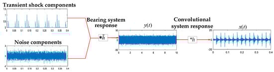
Figure 1.
The procedure illustrating transient feature extraction.
According to the convolution theorem, the fault transient feature extraction can be implemented in frequency domain.
where indicates inverse Fourier transform, and are the counterparts in frequency domain of and , respectively.
3. The Proposed Personalized Diagnosis Scheme for Bearings
As mentioned in Section 2.2, an adequate wavelet basis is crucial for wavelet filtering to extract bearing fault-induced transient features. That is, the higher degree the wavelet basis matches with the transient features to be extracted, the better the performance of feature extraction will be. In order to render wavelet filtering to maximize its effectiveness in the context of transient feature extraction, a personalized bearing fault diagnosis scheme is proposed on the basis of the FEM-based wavelet basis resulting from finite element dynamics simulation of the bearing.
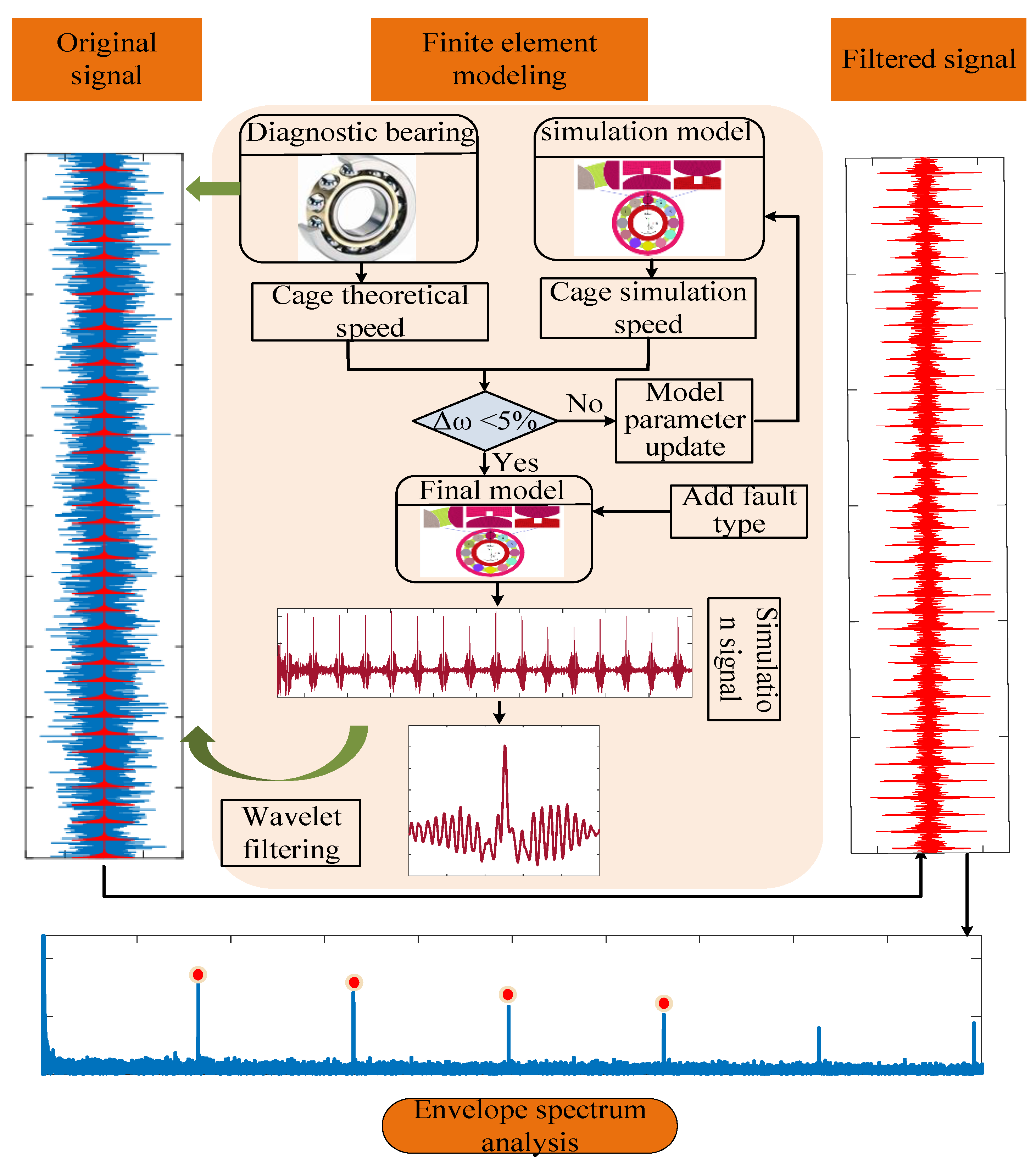
Figure 2 describes the flowchart of the proposed personalized diagnosis scheme for bearing faults. The main steps are elaborated on as follows.
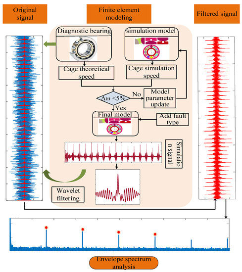
Figure 2.
The procedure of personalized diagnosis using FEM-based wavelet bases.
Step 1: Build the finite element model of the bearing to be diagnosed.
Identifying the geometry, material, load, and constraint characteristics of the bearing to be monitored, the finite element model can be built in terms of the FEM software LS-DYNA. The FEM model is subjected to continuous updating until the error of the bearing cage rotating speed between simulation results and those from theoretical calculation is no more than a prescribed threshold like 5%. Keep in mind that this process of modeling works in an offline fashion so that it does not increase computation burden on the consequent online diagnosis.
Step 2: Obtain a bearing specific FEM-based simulation signal.
Various fault models are inserted into the FEM models to simulate the dynamic responses (vibration signals) of the bearings with faults. Since the simulation signal is free of noise originating from adjacent components and measure devices, the transient features due to fault-induced impacts are obvious.
Step 3: Construct a bearing-specific FEM-based wavelet basis.
An arbitrary impulse response is isolated from the simulation signal, then it is transformed into a single-scale FEM-based wavelet basis without tension and compression by using the Matlab function pat2cwav, which is based on the principle of the least squares fitting method.
Step 4: Personalized diagnosis of bearing faults using the FEM-based wavelet basis.
Wavelet filtering is performed on vibration signals measured from real-world faulty bearings using the FEM-based wavelet bases. Hilbert transform is then employed to demodulate the filtered signals followed by using envelope spectrum to diagnose bearing faults by examining fault characteristic frequency. FEM-based wavelet bases come from the FEM models of the bearing at hand, so the FEM-based fault diagnosis method is bearing-specific and personalized.
4. The FEM Model Construction and Simulation
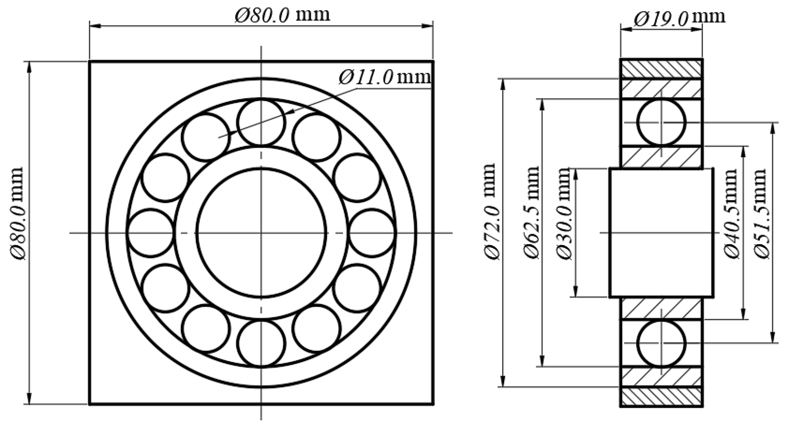
The subsequent personalized diagnosis experiments were conducted on the self-made rolling bearing fault test rig as shown in Figure 3, which is composed of one supporting and one test bearing, a radial loading device, a servo motor and its controller, an accelerometer sensor, and a data acquisition system. It is worth pointing out that the data acquisition system was made up of an accelerometer CA-YD-187T52332, a signal acquisition card NIUSB-4431, and a laptop with the Labview software. Meanwhile, the accelerometer sensor was positioned vertically on the outer surface of the bearing housing. The outer ring of the NU306 bearing was installed on the housing in an interference fit. The test rig can simulate different bearing faults under various operating conditions. As a pioneering work using FEM simulation to obtain a wavelet basis for implementing personalized fault diagnosis, only outer and inner ring faults which are relatively easy to be detected are investigated herein. In the experiments depicted in the next section, NU306 bearings are tested, of which the geometric dimensions are illustrated in Figure 4. In addition, a radial load of 3000 N by screwing a thrust device JL1086 is applied to the bearing, and the load was measured by a pressure strain gauge. A rotating speed of 2100 r/m (35 Hz) and a sampling frequency of 12 kHz are adopted.
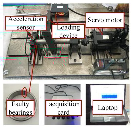
Figure 3.
The bearing test bench.
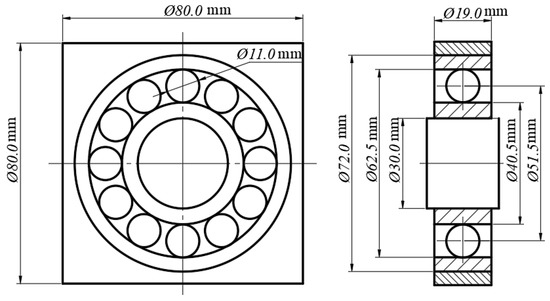
Figure 4.
The geometric dimensions of an NU306 bearing.
According to the operating conditions of the bearings in the coming experiment test, the FEM modeling process of the NU306 bearing was analyzed.
- (1)
- Determine element type and model material.
In general, the three-dimensional (3D) finite element modeling provides a simulation closest to real vibration but at the expense of computation burden. On the other hand, it is reported that the 2D FEM is able to attain an agreeable simulation [31,32]. For creating FEM models, the 2D shell element is employed to model the geometry of the bearings. Each 2D element contains four nodes, each of which is of two freedoms of movement in x and y directions. All of the bearing components are modeled using materials with elastic property, in view of the elastic deformation within bearings. The main material parameters are listed in Table 1.

Table 1.
The material parameters of NU306 bearing.
- (2)
- Generate finite element mesh.
The following three issues need to be considered to determine the optimal mesh size. ① The computation time should be as short as possible while satisfying the calculation accuracy. ② The rolling elements are supposed to keep constant contact with the raceways. ③ The vibration noise due to grid regular polygon effect should be minimized [33,34,35]. A trial-and-error method was carried out to determine the size of quadrangular meshes including 1 mm, 0.5 mm, and 0.25 mm. By observing the smoothness of the contact force curve between the bearing rollers and rings, a mesh size of 0.25 mm was finally employed to discretize the model by which the contact force curve is the smoothest. Local mesh refinement is performed at fault zone and adjacent regions, leading to a total of 61,380 nodes and about 58,990 elements.
To acquire precise dynamic responses, there is a typical recommendation to perform at least 20 elements-per-wavelength (EPW) for transient structural dynamics analysis in wave propagation research. In transient dynamics analysis, the outer ring is usually considered a thin plate, and the speed of the bending wave is calculated as:
where E, , and represent the elastic modulus, density, and Poisson’s material ratio, respectively. T stands for the thickness of the thin plate. Substituting the relevant data into the above equation, the bending wave speed is calculated to be 2007.73 m/s, which corresponds to the wavelength data of 0.0675 m. Hence, a mesh of 0.25 mm corresponds to 270 EPW, which is far greater than 20 EPW and satisfies the condition that the rolling body can be in continuous contact.
- (3)
- Set up constraints.
In order to simulate the actual operating conditions of the bearings, the nodes on the outer surface of the outer ring are fixed due to their interference fit in the bearing housing. An equivalent radial load of Q = 3000 N is applied to the inner surface of the inner ring in the positive direction of the Y-axis. A clockwise rotating speed of ni = 2100 r/min (ωi = 220 rad/s) is adopted on the inner ring. To simulate the faults that occur in the experimental bearings tested in the next section, faults in outer and inner rings are studied. The fault size was 1 mm × 1 mm with the shape of a rectangular crater.
- (4)
- Set up contact type
There is a highly nonlinear contact behavior between the rolling elements and other parts as bearings running. A proper contact pair is crucial to solving the contact problem. Compared with node-to-surface contact, surface-to-surface contact allows coordinated stiffness matrix calculation and is not limited by the shape of the rigid body surface, so the automatic surface-to-surface contact type is chosen to simulate the contacts in bearings. The inner raceway of the outer ring, outer raceway of the inner ring, and cage are defined as the master segments, while the rollers are regarded as the slave segments. NU306 bearings have 12 rollers with each having 3 contact pairs with the outer ring, inner ring, and retainer, respectively. Both of the static friction coefficients between the rollers and the raceways and the cage are defined as 0.01, while the kinetic friction coefficient is 0.005.
- (5)
- Hourglass control
In dynamic response calculations, the hourglass phenomenon can distort the meshes and bias the results toward the null. In order to control the hourglass phenomenon, some measures should be taken such as generating meshes as uniformly as possible, regulating line type and quadratic coefficients to increase the bulk viscosity of models, as well as utilizing full integration operations. Therefore, the hourglass coefficient is set to 0.1, the bulk viscosity coefficient 1.5, and the linear bulk viscosity coefficient 0.06 [36].
- (6)
- Set up output.
The output time interval of the simulation signal was tried with 10−4 s, 10−5 s, and 10−6 s for the test. By comparing the amount of information and the waveform of the simulated signals under different output time intervals, the output interval was set to 10−5 s.
- (7)
- Validate the model.
The difference in cage rotating speed between the FEM simulation result and the theoretical value is considered. The formula of theoretical value is defined as follows:
where and represent the inner ring and outer ring speed, respectively. The parameter denotes the diameter of the rollers; signifies the average diameter of the bearing. The cage speed error is expressed as follows:
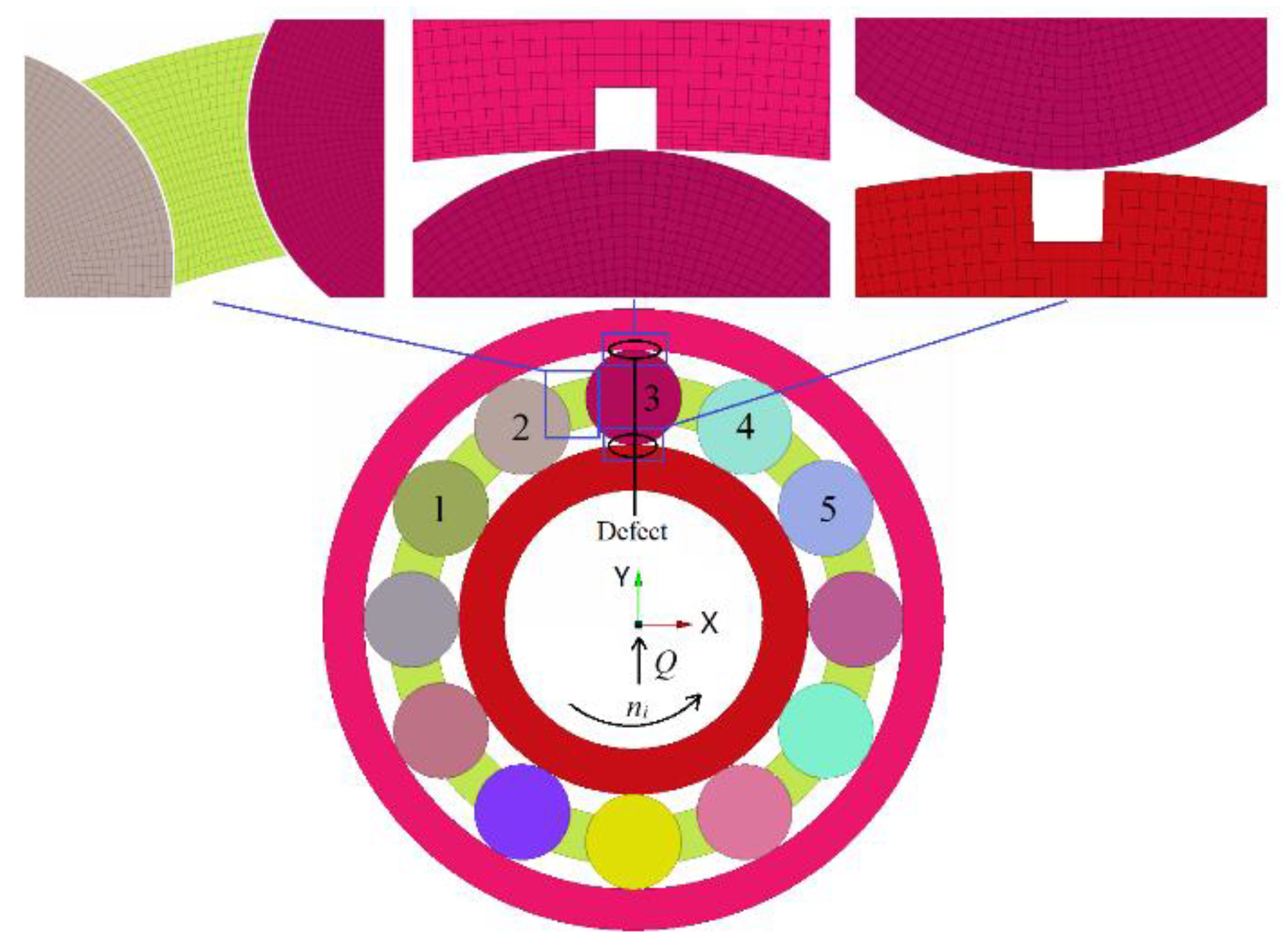
where is the cage speed resulting from the FEM simulation, and represents the theoretical one. By substituting the parameters illustrated at the beginning of Section 4 and Figure 4, the theoretical value of cage rotating speed is , while the average value of the FEM simulation model is . The cage speed error is according to the Equation (13), which validates the FEM model of the NU306 bearing shown in Figure 5.

Figure 5.
The FEM simulation model of NU306 bearing.
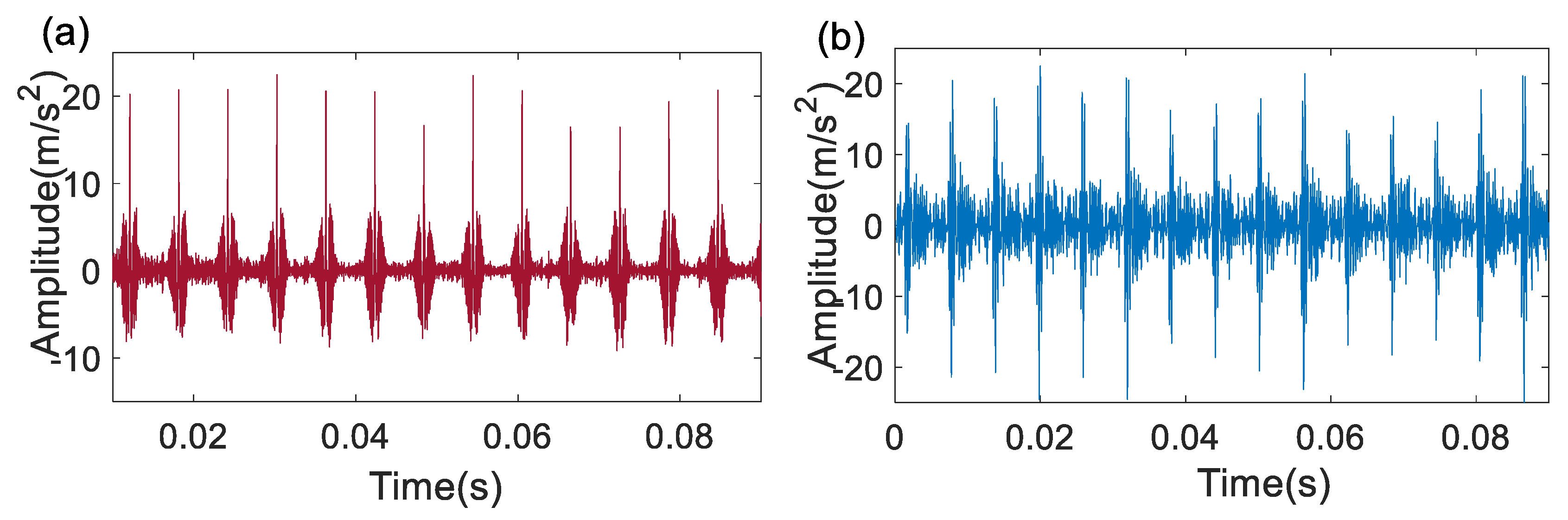
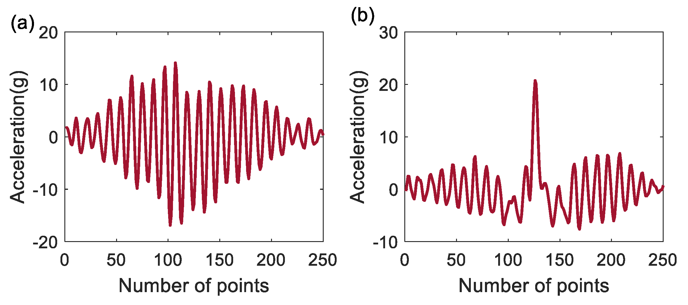
The vibration signals of NU306 bearing with outer ring fault are displayed in Figure 6, where Figure 6a,b come from the FEM model in Figure 5 and the experiments conducted on the test rig shown in Figure 3, respectively. The periods of two adjacent impacts within the simulated and the experiment signals are 0.006 s and 0.0058 s, respectively. Hence, the relative error is 3.3%, which further verifies the effectiveness of the bearing FEM model. Furthermore, the comparison between the simulated signal in Figure 6a and the experiment signal in Figure 6b demonstrates that the FEM technology can nearly perfectly duplicate a real-world problem. An FEM-based wavelet basis could be formulated from the FEM simulated signals. As the FEM models are specific to bearing type, fault location, bearing working condition, and bearing installation, the fault diagnosis based on the FEM-based wavelet bases is a so-called personalized diagnosis which is expected to overcome the drawbacks using the existing wavelet bases as the Morlet and impulse wavelet bases.

Figure 6.
Signals of an NU306 bearing with outer ring fault: (a) the simulated signal; (b) the experiment signal.
5. Experimental Investigation
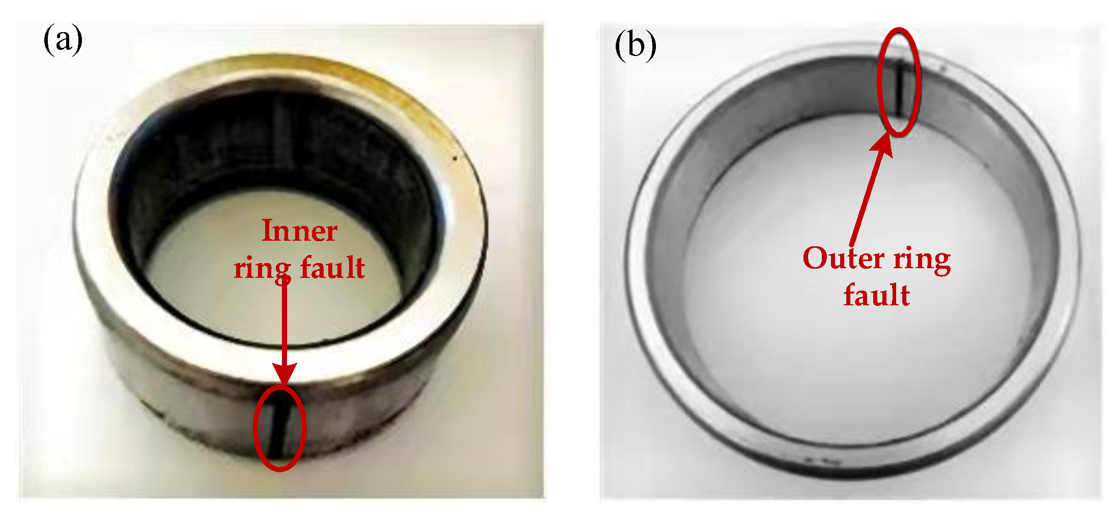
The defected inner and outer rings of NU306 bearings are shown in Figure 7, with their corresponding FEM-based wavelet bases illustrated in Figure 8a,b, respectively. An arbitrarily chosen impulse response is truncated from the finite element model simulated signals as shown in Figure 6a, and then transformed into an FEM-based wavelet basis using the pat2cwav function, which is specified by their discrete values in the time domain rather than an analytical expression.
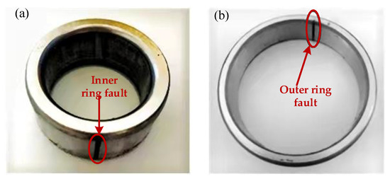
Figure 7.
The defect in (a) outer surface of inner ring and (b) inner surface of outer ring of NU306 bearing.

Figure 8.
The FEM-based wavelet bases: (a) for inner and (b) outer raceway faults.
Table 2 provides the main geometric parameters of the NU306 bearing. Fault vibration signals are then collected by running these defected bearings on the test rig shown in Figure 3, where the load on and rotating speed of the bearing, as well as sampling frequency, are specified in Section 4. From a certain equation of bearing fault characteristic frequency, the ball passing frequency of the inner ring and that of the outer ring can be derived as 254.85 Hz (BPFI) and 165.4 Hz (BPFO), respectively.
Table 2.
The geometric parameters of NU306 bearing.
5.1. Inner Raceway Fault
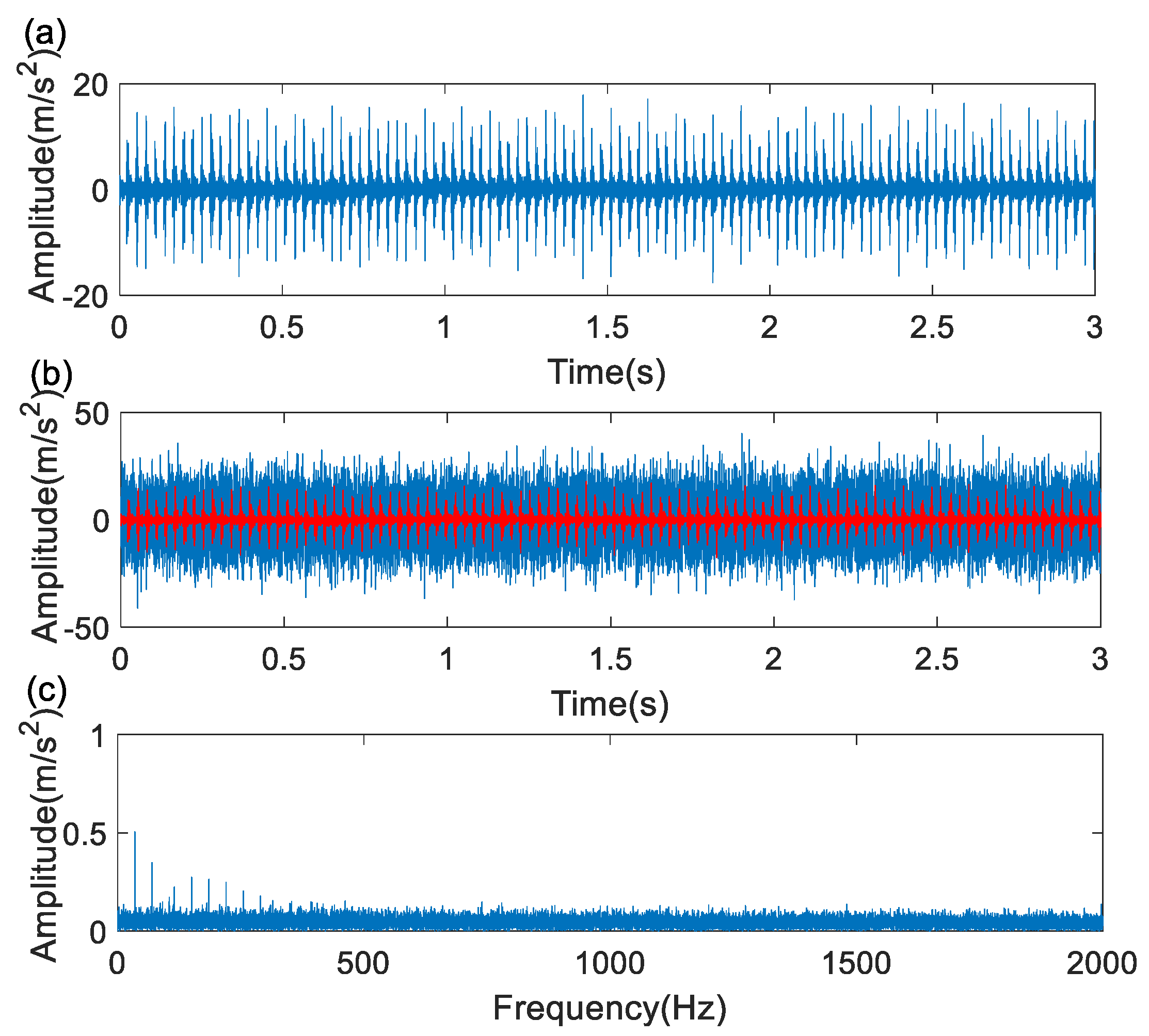
Figure 9a shows the vibration of the bearing with the inner ring fault, where the fault-induced impacts are considerably evident due to the fact that the defect has a sharp boundary and no interferences from adjacent mechanical components exist. Gaussian noise of 10 m/s2 amplitude is imposed on the experiment signal (Figure 9a) leading to a signal with the impacts submerged (Figure 9b). The objective of adding noise is to make the experiment signals trying to approach real-world ones where the effects of the signal transmission path and noise interferences from other components are nonnegligible. As a consequence, there are no distinct characteristic frequency components (BPFI) in the envelope spectrum (Figure 9c) of the noised signal (Figure 9b).
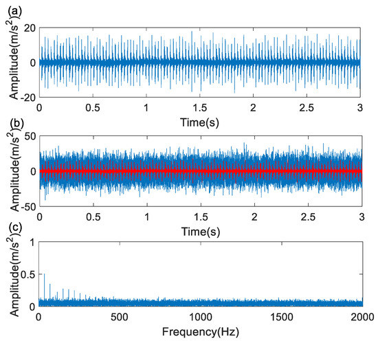
Figure 9.
The inner ring fault signal: (a) original signal; (b) noisy signal; (c) envelope spectrum.
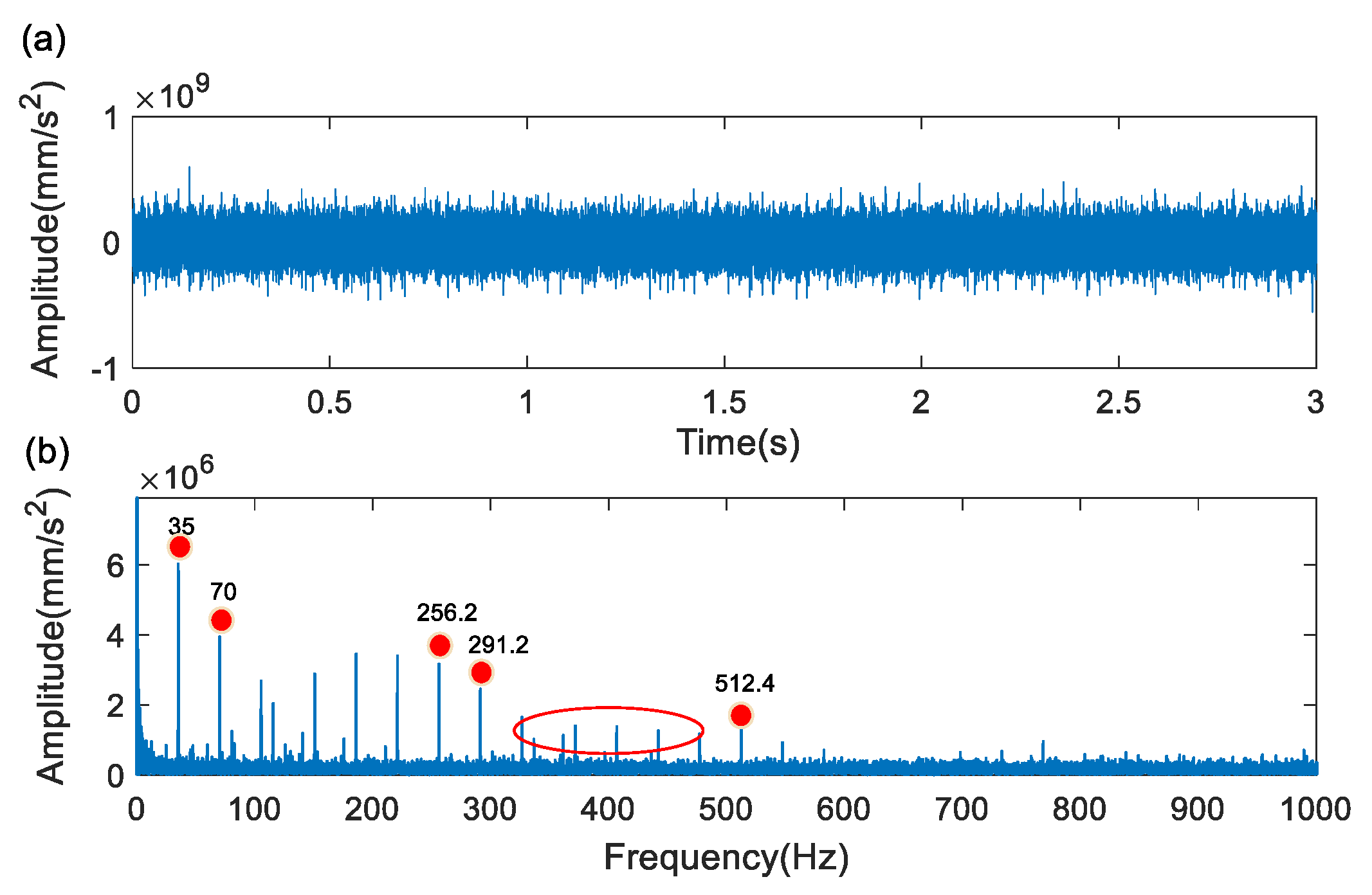
To test the personalized diagnosis method in the case of bearing inner raceway faults, the FEM-based wavelet basis (Figure 8a) is used in the context of wavelet filtering for transient feature extraction as described in Section 2.2. Although the transient impulses are not yet obvious enough in the filtered signal shown in Figure 10a, a dominant frequency component of 256.2 Hz (close to inner raceway defect-related frequency, BPFI = 254.85) and its harmonics (512.4 Hz, etc.) are dominant in the envelope spectrum shown in Figure 10b. In addition to the BPFI and its harmonics, it is seen that there are side-band components around 256.2 Hz at an interval of 35 Hz (corresponding to the bearing rotational speed of 1200 r/m). Moreover, the frequency of 35 Hz and its harmonics emerge in the low frequency band. Such side-band frequency and rotating frequency-related components further confirmed the existence of inner raceway fault.
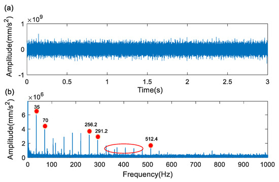
Figure 10.
Results of inner ring fault using FEM-base wavelet basis: (a) filtered signal; (b) envelope spectrum of the filtered signal.
5.1.1. Comparison with Morlet Wavelet
When a defect is present on one working surface of a bearing, impulse responses occur. The typical impulse response comprises an initial fast rise and a decaying part. There is a similarity between the decaying part of the Morlet wavelet and the decaying part of the typical impact-induced transients. The Morlet wavelet has been widely adopted in the field of fault transient feature extraction [37,38,39]. Actually, the Morlet wavelet is the product of a Gaussian window function and a sinusoidal signal, which can be represented as:
where represents the attenuation factor and denotes the center frequency. From the frequency-domain, the envelope factor determines the bandwidth of a wavelet filter. However, its physical meaning is not obvious enough, so the bandwidth parameter is defined as:
Replacing the above equation with the bandwidth parameter , its frequency-domain expression can be written as:
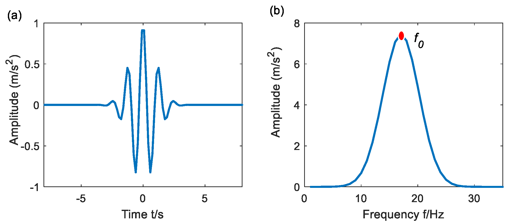
Figure 11a,b illustrate the time-domain and frequency-domain waveform of the Morlet wavelet respectively, for f0 = 1 Hz and β = 0.5 Hz. From Figure 11b, it is seen that the Morlet wavelet manifests as a window in frequency domain, satisfying the requirements of a bandpass filter such as narrow band, stability, and smoothness. To better pick up the transient impact features in vibration signals, bandwidth and center frequency should be chosen carefully to achieve an appropriate wavelet filter.
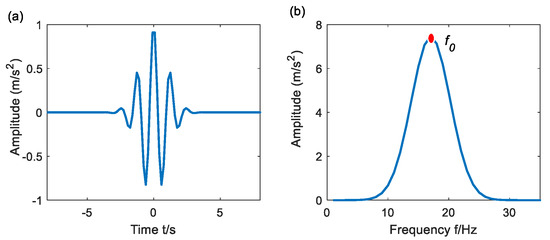
Figure 11.
An example of Morlet wavelet: (a) time-domain wavelet; (b) frequency-domain wavelet.
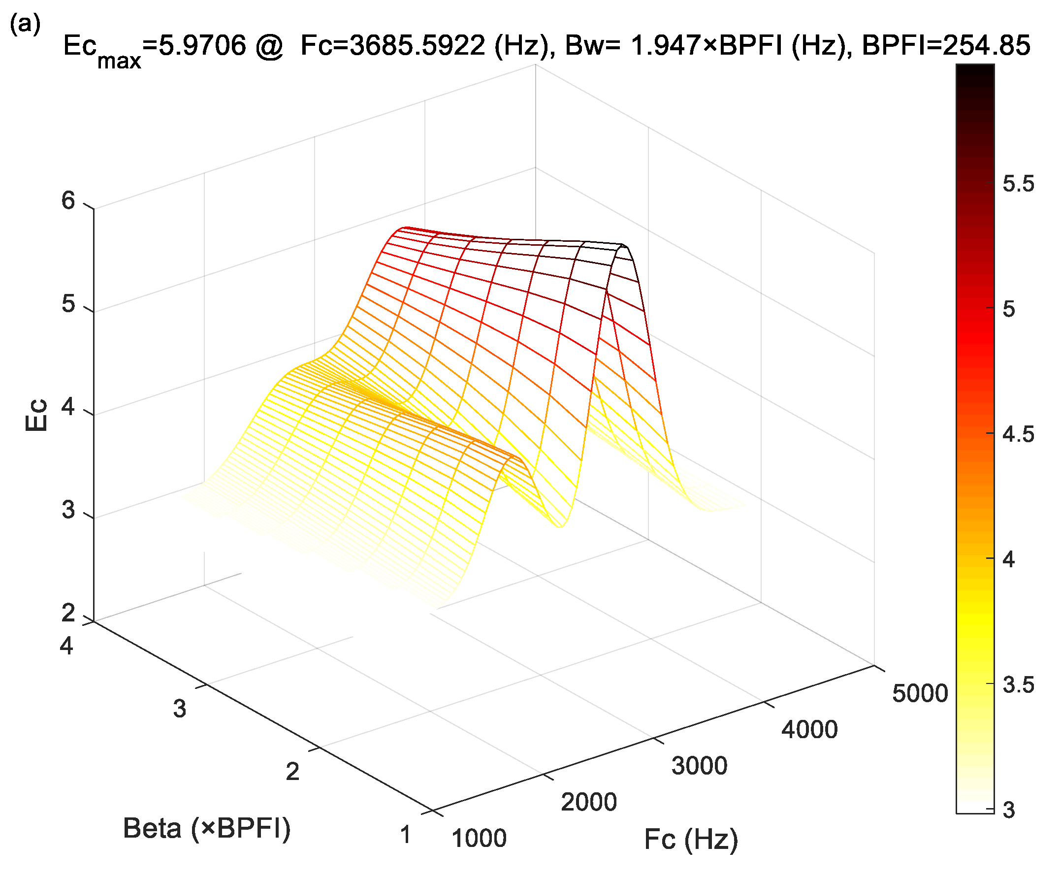
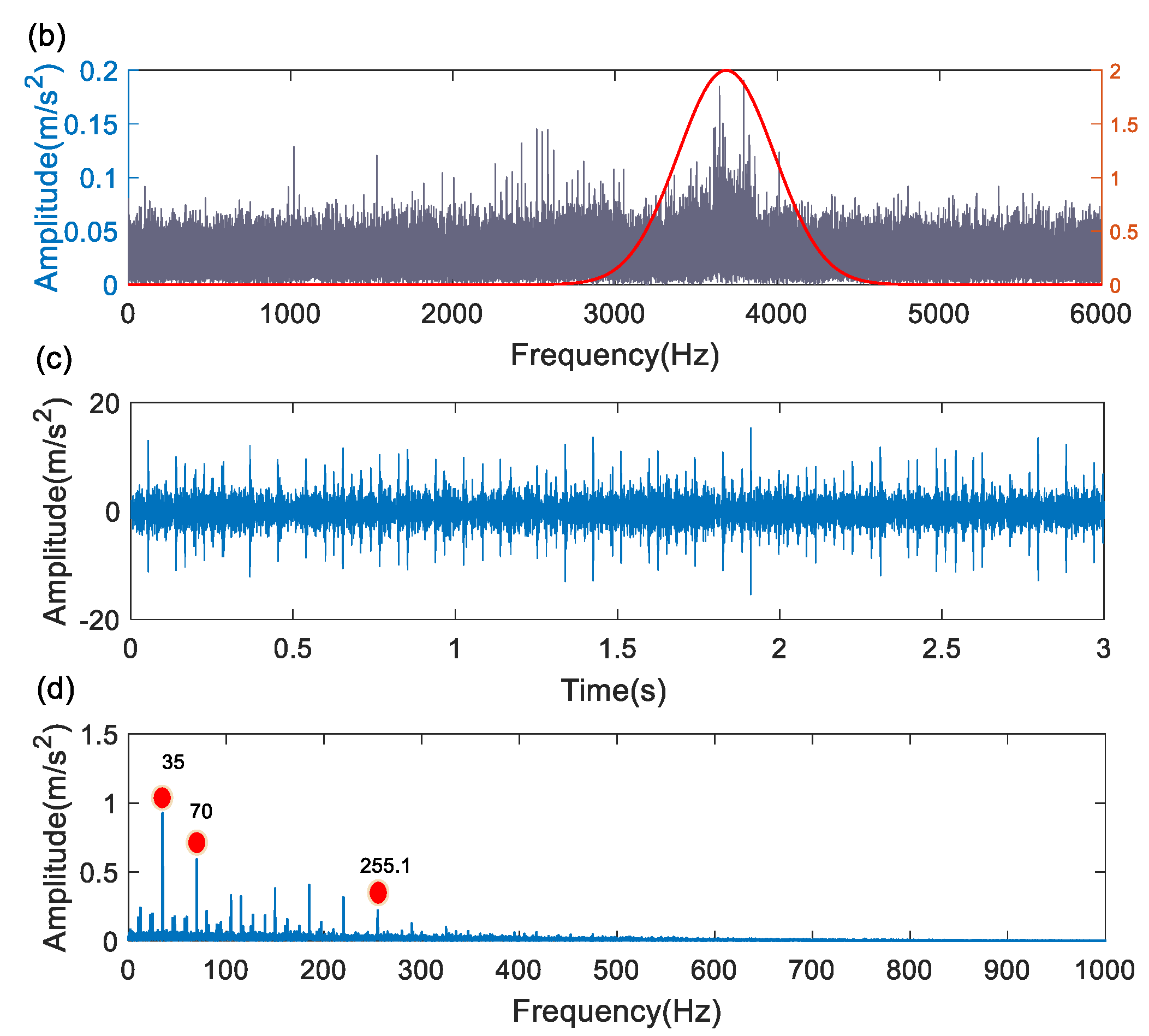
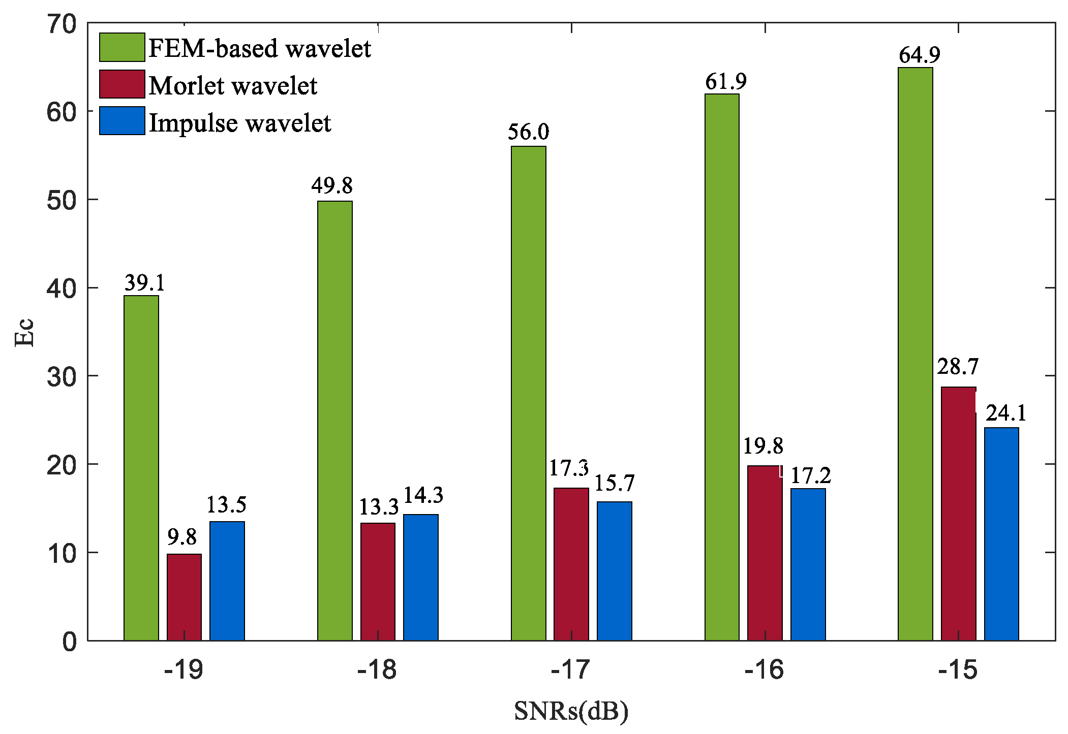
The noisy signal in Figure 9b was processed using the Morlet wavelet filter. The crest factor of the envelope spectrum (Ec) of the filtered signal is proposed as the optimization index to choose the optimal center frequency ( and bandwidth ( for the Morlet wavelet filter [12]. The index Ec is defined as:
where and represent the maximum and the root mean square (RMS) values of the envelope spectrum in the range of [, respectively; is the rotating frequency of the bearing; denotes the sampling frequency of the signal. To avoid the effect of rotating frequency, can be defined as 2. The bigger Ec means that the energy of the filtered signal is more concentrated and the periodicity of impulse transients is more obvious, and thus the quality of the filtered signal is better.
Figure 12a shows the variation of Ec with and . It is observed that Ec comes to its maximum value of 5.9706 when and . The frequency domain representations of the noisy signal along with the optimal Morlet filter are shown in Figure 12b. Figure 12c shows the filtered signal where the impact generated transients have been enhanced to a certain extent compared with Figure 9b. In Figure 12d, there is a frequency component of 255.1 Hz close to the BPFI = 254.85 Hz. Nevertheless, compared with Figure 10b, the harmonics of the characteristic frequency component and its side-band components are absent, which does not benefit from fault determination.
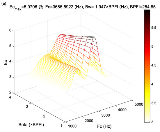
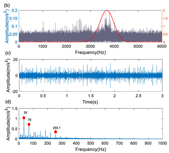
Figure 12.
Results of Morlet wavelet for inner ring fault: (a) the parameter selection of the Morlet wavelet filter; (b) the spectrum and optimal filter; (c) filtered signal; (d) the envelope spectrum of the filtered signal.
5.1.2. Comparison with Impulse Response Wavelet
The impulse response function has a unilateral attenuation characteristic [40]. As such, it is also among the wavelet bases commonly used to extract fault induced transient features, and its expression can be expressed as:
where represents the natural frequency and denotes the damping ratio. The parameters and represent the time shift and the support width of the wavelet, respectively.
By replacing the Morlet wavelet with the impulse response wavelet and conducting parameter optimization in the same manner as that of the Morlet wavelet, the wavelet filtering results are shown in Figure 13. Comparing Figure 13b with Figure 10b, it appears that in the envelope spectrum of the impulse response wavelet, the side-band components marked by the circle are absent, while they are obviously present in Figure 10b. Side-band components around fault characteristic frequencies are essential symptoms of inner ring faults.
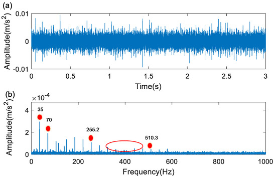
Figure 13.
Results of the impulse response wavelet for inner ring fault: (a) the filtered signal; (b) its envelope spectrum.
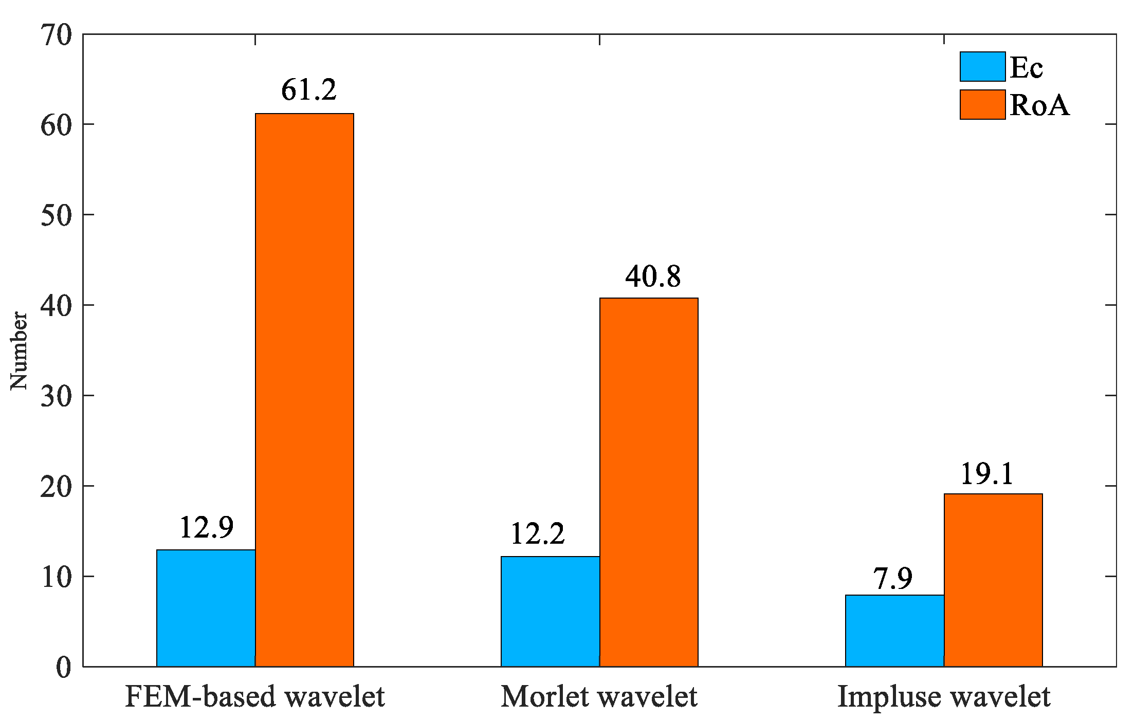
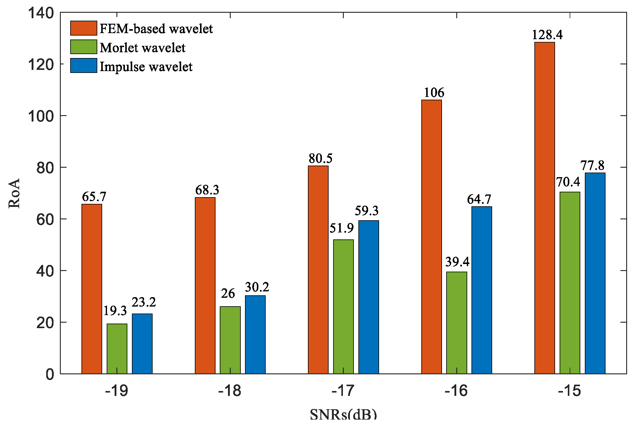
We proposed an index called the ratio of amplitude (RoA) to measure the quality of a wavelet filtering operation. The expression of RoA is formulated as:
where A denotes the amplitude of the fault characteristic frequency in the envelope spectrum; is the average value of the envelope spectrum. The higher the RoA value, the more pronounced the characteristic fault impact is, i.e., the better the filtering results.
The quantitative comparison of the FEM-based, Morlet, and impulse response wavelet bases are illustrated in Figure 14 in terms of Ec and RoA index. Both the indices demonstrate that the FEM-based wavelet basis is superior to the other two popular bases.

Figure 14.
The Ecs and RoAs of the filtered signals by three wavelet bases for inner ring fault.
5.2. Outer Raceway Fault
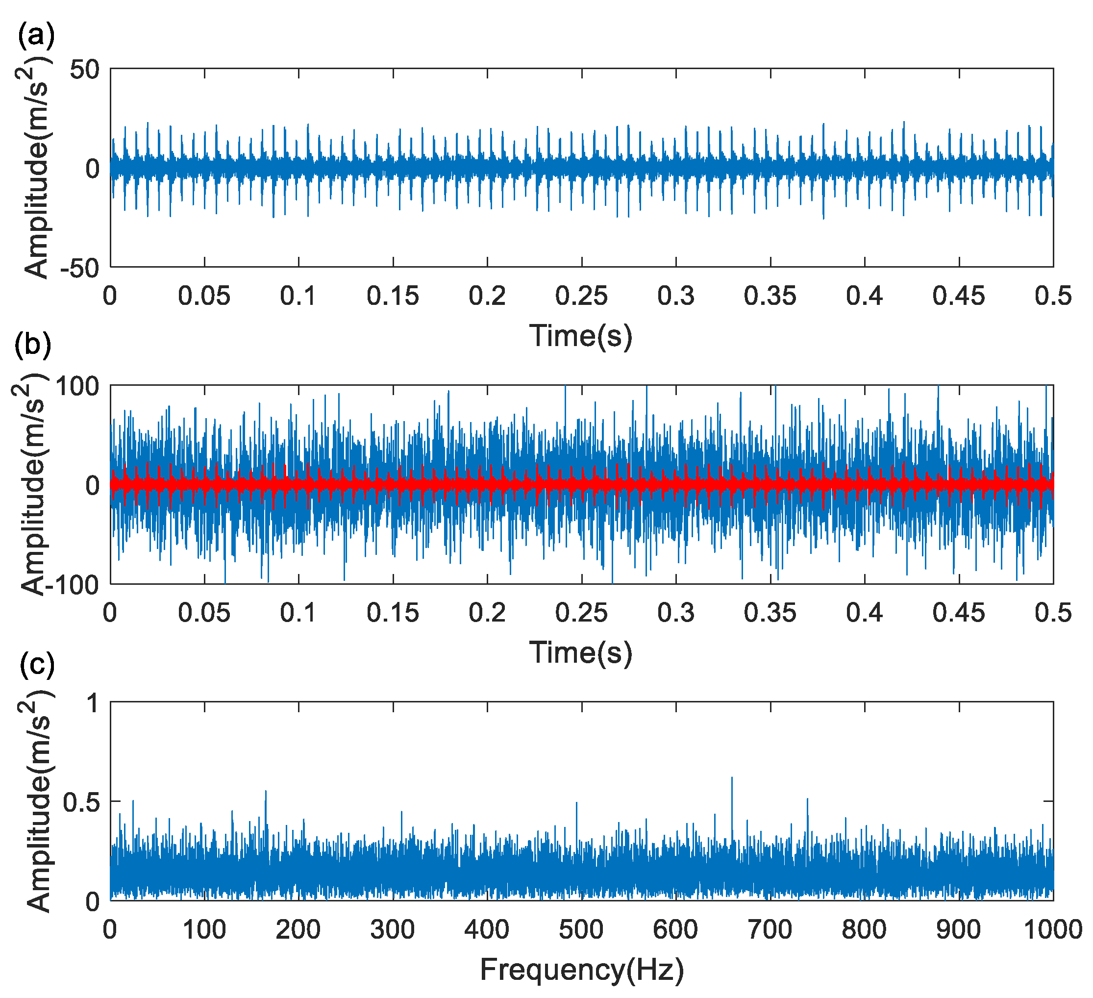
The performance of the FEM-based wavelet basis has been validated on inner ring fault feature extraction in the last section. In order to further test the proposed method, the investigations on outer ring fault were carried out. Installing the defected outer ring (Figure 7b) into the test rig (Figure 3), the signal representing outer raceway fault was attained and is shown in Figure 15a. The experiment signal was injected with Gaussian noise of to get a corrupted signal with an SNR of −15 dB as shown in Figure 15b, of which the envelope spectral (Figure 15c does not present any frequency components) is associated with the outer raceway faults.
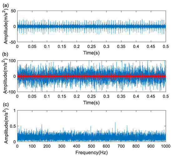
Figure 15.
The outer ring fault signal: (a) original signal; (b) noisy signal; (c) envelope spectrum.
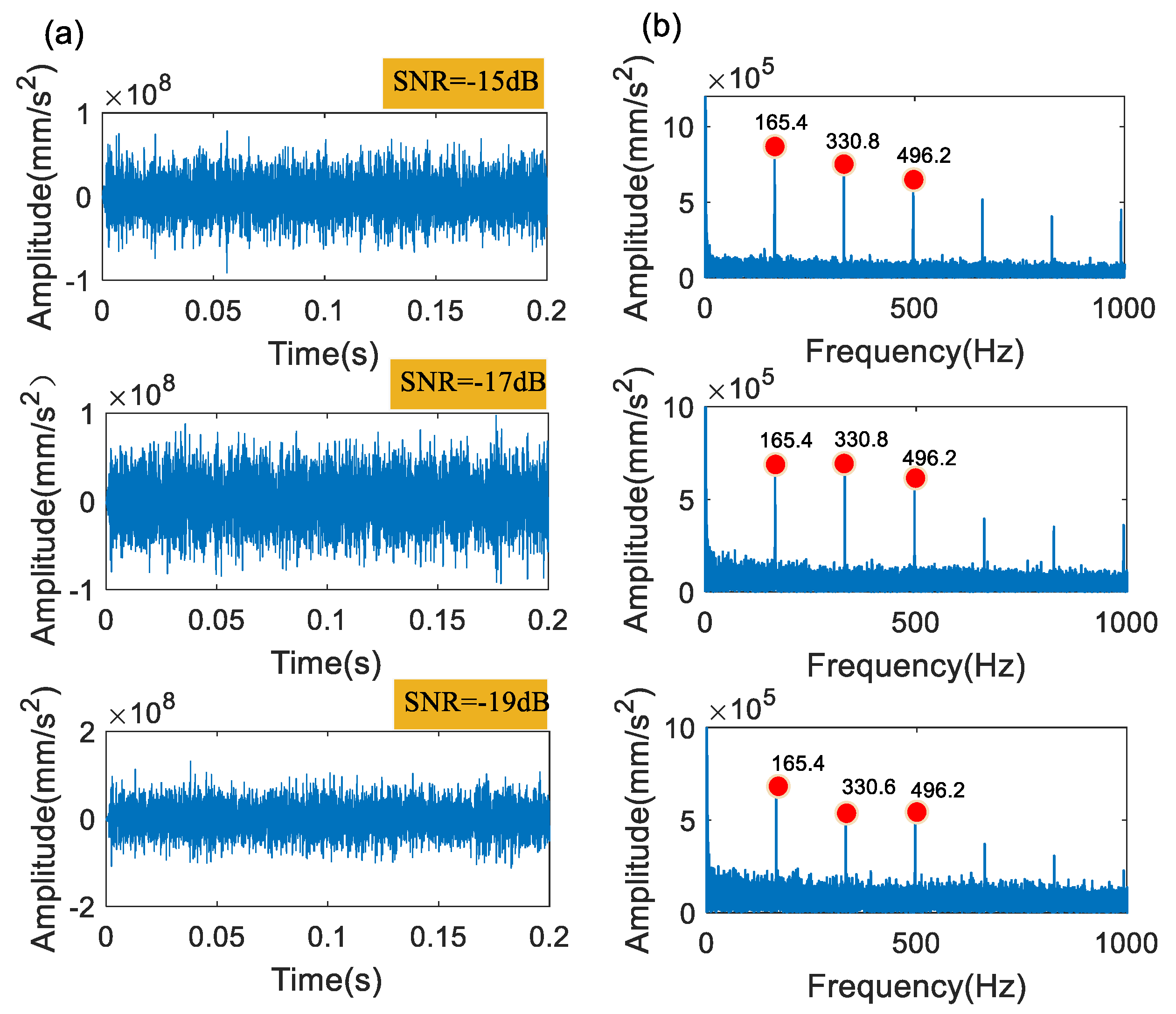
The personalized FEM-based wavelet basis has been formulated as Figure 8b, which is employed to filter the outer raceway fault signals with various SNRs. It is observed in Figure 16 that the characteristic frequency component of outer raceway fault (BPFO) and its harmonics up to the 5th are distinct, even for the case of −19 dB SNR.

Figure 16.
Results of FEM-based wavelet of outer ring fault at different SNRs: (a) filtered signal; (b) the envelope spectrum of the corresponding filtered signal.
5.2.1. Comparison with Morlet Wavelet
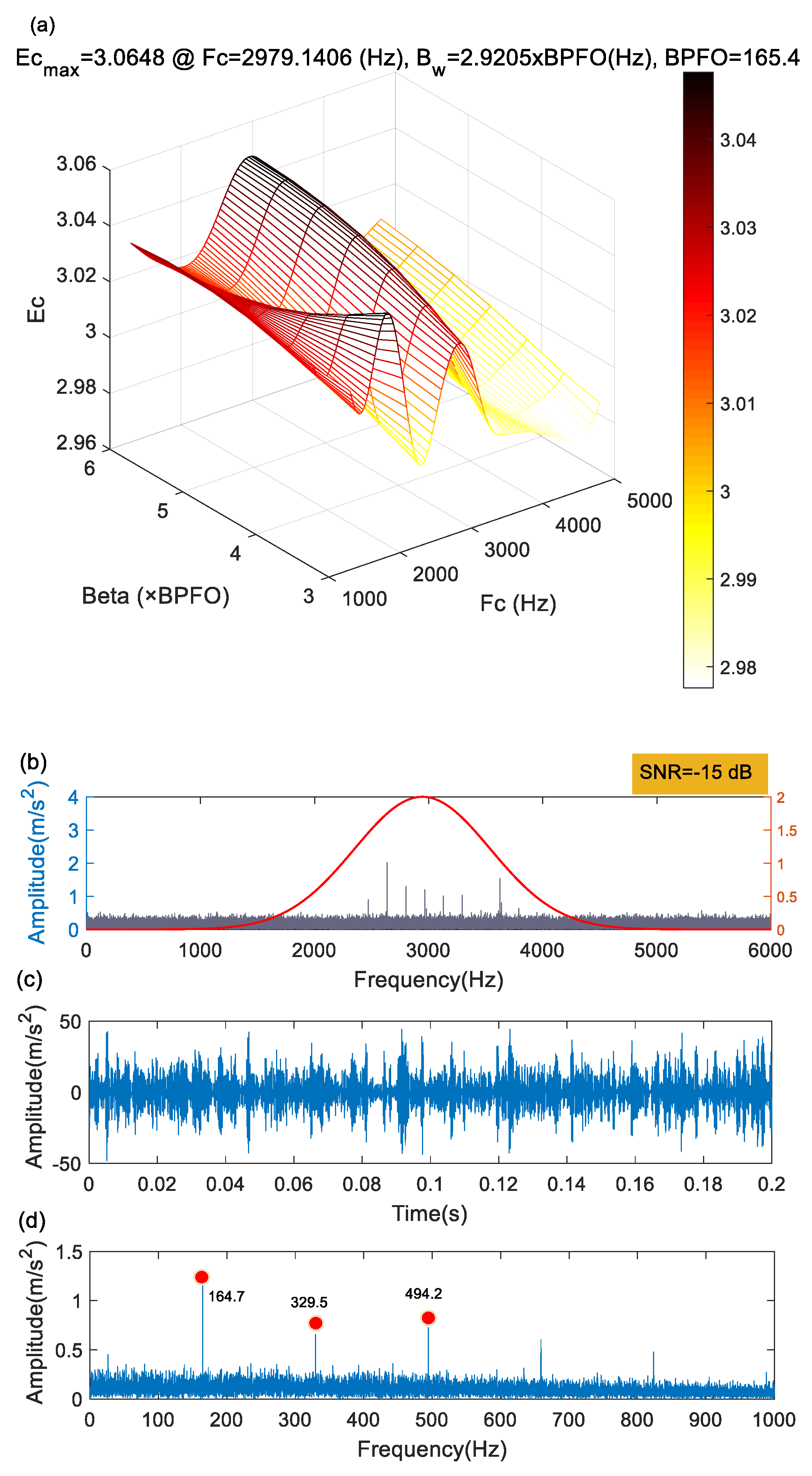
In the case of −15 dB SNR, Ec arrives at its maximum when and as shown in Figure 17a. Applying this Morlet filter to the corrupted signal (Figure 17b) results in the filtered signal (Figure 17c) along with its envelope spectral (Figure 17d) where the BPFO and its harmonics are predominant. However, the noise seems heavier than that using the FEM-based wavelet basis as shown in the top right-hand corner of Figure 16.

Figure 17.
Results of Morlet wavelet of outer ring fault at the SNR of −15 dB: (a) the parameter selection of the Morlet wavelet filter; (b) the spectrum and optimal filter; (c) filtered signal; (d) the envelope spectrum of the filtered signal.
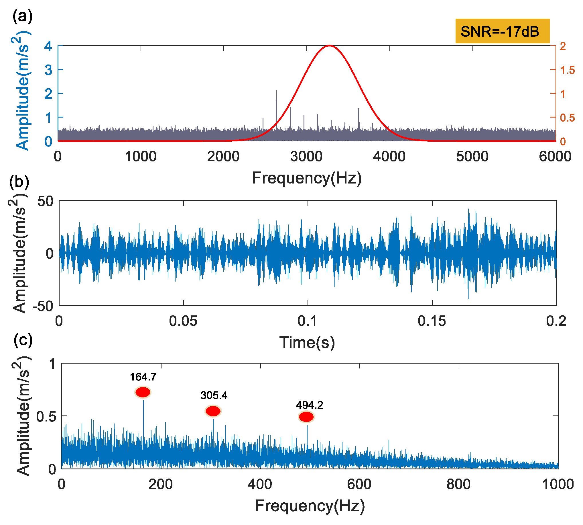
Figure 18 and Figure 19 show the results, respectively, for the SNR of −17 dB and −19 dB using the Morlet wavelet. The results reveal that the performance of Morlet wavelet decreases with the SNR. For the SNR of −19 dB, the BPFO component can be observed but with heavy noise in the absence of its harmonics.

Figure 18.
Results of Morlet wavelet on outer ring fault at the SNR of −17 dB: (a) the signal spectrum and optimal filter; (b) filtered signal; (c) the envelope spectrum of the filtered signal.
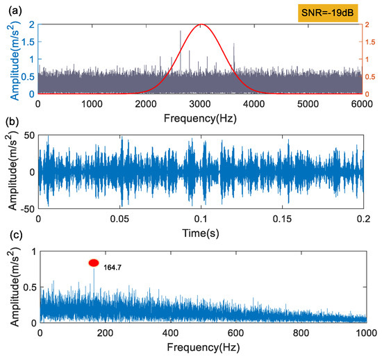
Figure 19.
Results of Morlet wavelet on outer ring fault at the SNR of−19 dB: (a) the signal spectrum and optimal filter; (b) filtered signal; (c) the envelope spectrum of the filtered signal.
5.2.2. Comparison with Impulse Response Wavelet
The impulse response wavelet has also been applied to the signal corrupted with various noise levels of −15 dB, −17 dB, and −19 dB. The result in the case of −15 dB is shown in Figure 20 while those of −17 dB and −19 dB have been omitted for brevity. The component of BPFI and its harmonics appear in the envelope spectrum but with noise stronger than those in the FEM-based (Figure 16) and Morlet envelope spectrum (Figure 17d).
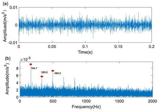
Figure 20.
Results of impulse response wavelet on inner ring fault: (a) filtered signal; (b) the envelope spectrum of the filtered signal.
Quantitative assessments of the performance of such three wavelet bases for the feature extraction of outer ring fault are illustrated in Figure 21 and Figure 22 in terms of RoA and Ec. In both Figure 21 and Figure 22, it is evident that the proposed personalized FEM-based wavelet has obvious advantages over the two commonly used Morlet and impulse response wavelets with respect to fault feature extraction.
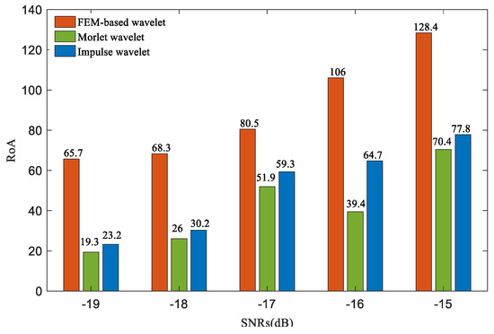
Figure 21.
The RoAs of filtered signals of outer ring fault with three wavelet bases at different SNRs.
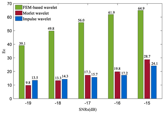
Figure 22.
The Ecs of filtered signals of outer ring fault with three wavelet bases at different SNRs.
6. Conclusions
Fault samples are small-sized, if any exist at all. Moreover, fault signatures vary with bearing type, fault location, and working and installation conditions, thus presenting a personalized behavior. Taking the abovementioned issues into consideration, a novel FEM-based wavelet basis construction paradigm was proposed in the current work based on a bearing FEM simulation. Fault feature extraction was achieved by utilizing the FEM-based wavelet basis in the framework of wavelet filtering. Such a feature extraction procedure is personalized because the explored wavelet bases are specific to bearing type, fault location, operating and installation conditions. According to the results of the experiment data, the main conclusions could be drawn as follows.
(1) The personalized FEM-based wavelet bases are formulated from simulated vibration response of the FEM simulation of a specific bearing. For such bearings, the similarity between the FEM-based bases is therefore rather better than those of Morlet and the impulse response wavelet bases, thus inclined to improve feature extraction and fault diagnosis.
(2) The proposed FEM-based wavelet bases are not only more compatible and robust than the commonly used adaptive Morlet wavelet and impulse response wavelet, but immune to signal transmission path and without parameter identification. The results of the two experiment cases of inner and outer raceway faults demonstrate that the FEM-based wavelet bases are superior to the other two wavelet bases with a prescribed mathematical expression with respect to fault feature extraction.
(3) Another contribution of the feature extraction by FEM-based wavelet bases to personalized fault diagnosis lies in the fact that it discovers a completely novel way to create wavelet bases agreeing better with the fault signature to be explored. Likewise, such an idea could be applicable to gear and rotor fault diagnosis and so on.
The experiment results have preliminarily validated the proposed FEM-based wavelet basis generation, but some questions deserve further investigation.
(1) The sampling frequency of the FEM simulation signal has a serious effect on the resulted FEM-based wavelet bases, for which to match well with actual bearing fault-induced impacts, such sampling frequency has to be chosen carefully. The trial-and-error method used in the present work is computationally expensive.
(2) The FEM model updating method employed in the present study is relatively primitive so that it may fail to accommodate a complicated mechanical system which comprises a lot of parts involving bearings, gears, and rotors, etc.
(3) It could be an interesting topic to develop a parametric modeling method to enable a fast, convenient, and cost-effective approach to implementing FEM dynamic simulation of any bearings once their geometrical dimensions, fault type, installation, and working condition parameters are provided.
Author Contributions
Conceptualization, L.Z. (Long Zhang) and L.Z. (Lijuan Zhao); methodology, L.Z. (Long Zhang); software, L.Z. (Lijuan Zhao); validation, B.C., L.Z. (Lijuan Zhao), H.Z., and Y.L.; formal analysis, L.Z. (Lijuan Zhao); investigation, L.Z. (Long Zhang) and L.Z. (Lijuan Zhao); resources, L.Z. (Long Zhang); data curation, J.Y. and W.T.; writing—original draft preparation, L.Z. (Long Zhang) and L.Z. (lijuan Zhao); writing—review and editing, L.Z. (Long Zhang) and L.Z. (Lijuan Zhang); visualization, L.Z. (Lijuan Zhao); supervision, L.Z. (Long Zhang); project administration, L.Z. (Long Zhang); funding acquisition, L.Z. (Long Zhang). All authors have read and agreed to the published version of the manuscript.
Funding
This work was supported by the National Science Foundation of China (No. 51665013), the Natural Science Foundation of Jiangxi Province (No. 20212BAB204007), the Jiangxi Province Graduate Student Innovation Project (No. YC2020-S335 and YC2021-S422), and the Science Research Project of the Education Department of Jiangxi Province (No. GJJ200616).
Institutional Review Board Statement
Not applicable.
Informed Consent Statement
Not applicable.
Data Availability Statement
The data used to support the finding of this study are available from the corresponding author upon request.
Conflicts of Interest
The authors declare no conflict of interest.
References
- Kuncan, M. An intelligent approach for bearing fault diagnosis: Combination of 1D-LBP and GRA. IEEE Access 2020, 8, 137517–137529. [Google Scholar] [CrossRef]
- Nguyen, V.C.; Hoang, D.T.; Tran, X.T.; Van, M.; Kang, H.J. A Bearing Fault Diagnosis Method Using Multi-Branch Deep Neural Network. Machines 2021, 9, 345. [Google Scholar] [CrossRef]
- Wang, J.; Qiao, W.; Qu, L. Wind turbine bearing fault diagnosis based on sparse representation of condition monitoring signals. IEEE Trans. Ind. Appl. 2018, 55, 1844–1852. [Google Scholar] [CrossRef]
- Yuan, R.; Lv, Y.; Song, G. Multi-fault diagnosis of rolling bearings via adaptive projection intrinsically transformed multivariate empirical mode decomposition and high order singular value decomposition. Sensors 2018, 18, 1210. [Google Scholar] [CrossRef] [Green Version]
- Pan, Z.Z.; Meng, Z.; Chen, Z.J.; Shi, Y. A two-stage method based on extreme learning machine for predicting the remaining useful life of rolling-element bearings. Mech. Syst. Signal Process. 2020, 144, 106899. [Google Scholar] [CrossRef]
- Pham, M.-T.; Kim, J.-M.; Kim, C.H. 2D CNN-Based Multi-Output Diagnosis for Compound Bearing Faults under Variable Rotational Speeds. Machines 2021, 9, 199. [Google Scholar] [CrossRef]
- Yuan, H.; Wu, N.; Chen, X.; Wang, Y. Fault diagnosis of rolling bearing based on shift invariant sparse feature and optimized support vector machine. Machines 2021, 9, 98. [Google Scholar] [CrossRef]
- Pan, H.; Xu, H.; Zheng, J.; Su, J.; Tong, J. Multi-class fuzzy support matrix machine for classification in roller bearing fault diagnosis. Adv. Eng. Inform. 2022, 51, 101445. [Google Scholar] [CrossRef]
- Zhang, J.Q.; Sun, Y.; Guo, L.; Gao, H.L.; Hong, X.; Song, H.L. A new bearing fault diagnosis method based on modified convolutional neural networks. Chin. J. Aeronaut. 2020, 33, 439–447. [Google Scholar] [CrossRef]
- Xu, Y.; Zhang, K.; Ma, C.; Cui, L.; Tian, W. Adaptive Kurtogram and its applications in rolling bearing fault diagnosis. Mech. Syst. Signal Process. 2019, 130, 87–107. [Google Scholar] [CrossRef]
- Xin, Y.; Li, S.; Zhang, Z.; An, Z.; Wang, J. Adaptive reinforced empirical Morlet wavelet transform and its application in fault diagnosis of rotating machinery. IEEE Access 2019, 7, 65150–65162. [Google Scholar] [CrossRef]
- Zhang, L.; Xiong, G.L.; Huang, W.Y. New procedure and index for the parameter optimization of complex wavelet-based resonance demodulation. J. Mech. Eng. 2015, 51, 129–138. [Google Scholar] [CrossRef]
- Shi, G.; Qin, C.; Tao, J.; Liu, C. A VMD-EWT-LSTM-based multi-step prediction approach for shield tunneling machine cutterhead torque. Knowl.-Based Syst. 2021, 228, 107213. [Google Scholar] [CrossRef]
- Yu, H.; Ming, L.J.; Run, S.M.; Zhao, S.-P. A hybrid model for financial time series forecasting—integration of EWT, ARIMA with the improved ABC optimized ELM. IEEE Access 2020, 8, 84501–84518. [Google Scholar] [CrossRef]
- Zeng, W.; Yuan, J.; Yuan, C.; Wang, Q.; Liu, F.; Wang, Y. Classification of myocardial infarction based on hybrid feature extraction and artificial intelligence tools by adopting tunable-Q wavelet transform (TQWT), variational mode decomposition (VMD) and neural networks. Artif. Intell. Med. 2020, 106, 101848. [Google Scholar] [CrossRef]
- Miao, Y.; Zhang, B.; Zhao, M.; Lin, J. Period-oriented multi-hierarchy deconvolution and its application for bearing fault diagnosis. ISA Trans. 2021, 114, 455–469. [Google Scholar] [CrossRef]
- Wang, Z.; Zhou, J.; Du, W.; Lei, Y.; Wang, J. Bearing fault diagnosis method based on adaptive maximum cyclostationarity blind deconvolution. Mech. Syst. Signal Process. 2022, 162, 108018. [Google Scholar] [CrossRef]
- Yan, C.; Zhao, M.; Lin, J.; Ding, C. Segmentation MED method based on kurtosis-frequency curve and its application in bearing diagnosis. Meas. Sci. Technol. 2021, 32, 115004. [Google Scholar] [CrossRef]
- Miao, Y.; Zhang, B.; Lin, J.; Zhao, M.; Liu, H.; Liu, Z.; Li, H. A review on the application of blind deconvolution in machinery fault diagnosis. Mech. Syst. Signal Process. 2022, 163, 108202. [Google Scholar] [CrossRef]
- Qin, Y.; Xiang, J.F.; Mao, Y.F. Weak transient fault feature extraction based on an optimized Morlet wavelet and kurtosis. Meas. Sci. Technol. 2016, 27, 085003. [Google Scholar] [CrossRef]
- Liu, H.; Huang, W.; Wang, S.; Zhu, Z. Adaptive spectral kurtosis filtering based on Morlet wavelet and its application for signal transients detection. Signal Process. 2014, 96, 118–124. [Google Scholar] [CrossRef]
- He, G.; Ding, K.; Lin, H. Fault feature extraction of rolling element bearings using sparse representation. J. Sound Vib. 2016, 366, 514–527. [Google Scholar] [CrossRef]
- LI, Y.G.; Liu, J.; Zhang, J.P. Signature extracting method of the fault rubbing rotor based on measured impulse response. J. Mech. Eng. 2007, 43, 224–228. [Google Scholar] [CrossRef]
- Fan, L.; Wang, S.; Wang, X.; Han, F.; Lyu, H.-W. Nonlinear dynamic modeling of a helicopter planetary gear train for carrier plate crack fault diagnosis. Chin. J. Aeronaut. 2016, 29, 675–687. [Google Scholar] [CrossRef] [Green Version]
- Monteiro, H.A.S.; Novelli, L.; Fonseca, G.M.; Pitangueira, R.L.S.; Barros, F.B. A new approach for physically nonlinear analysis of continuum damage mechanics problems using the generalized/extended finite element method with global-local enrichment. Eng. Anal. Bound. Elem. 2020, 113, 277–295. [Google Scholar] [CrossRef]
- Liu, X.Y.; Huang, H.Z.; Xiang, J.W. A personalized diagnosis method to detect faults in gears using numerical simulation and extreme learning machine. Knowl.-Based Syst. 2020, 195, 105653. [Google Scholar] [CrossRef]
- Gao, Y.; Liu, X.Y.; Xiang, J.W. FEM simulation-based generative adversarial networks to detect bearing faults. IEEE Trans. Ind. Inform. 2020, 16, 4961–4971. [Google Scholar] [CrossRef]
- Song, W.L.; Xiang, J.W.; Zhong, Y.T. A simulation model based fault diagnosis method for bearings. J. Intell. Fuzzy Syst. 2018, 34, 3857–3867. [Google Scholar] [CrossRef]
- Liu, X.Y.; Huang, H.Z.; Xiang, J.W. A personalized diagnosis method to detect faults in a bearing based on acceleration sensors and an FEM simulation driving support vector machine. Sensors 2020, 20, 420. [Google Scholar] [CrossRef] [Green Version]
- Yankovskii, A.P. Applying the explicit time central difference method for numerical simulation of the dynamic behavior of elastoplastic flexible reinforced plates. J. Appl. Mech. Tech. Phys. 2017, 58, 1223–1241. [Google Scholar] [CrossRef]
- Singh, S.; Howard, C.Q.; Hansen, C.H.; Köpke, U.G. Analytical validation of an explicit finite element model of a rolling element bearing with a localised line spall. J. Sound Vib. 2018, 416, 94–110. [Google Scholar] [CrossRef]
- Singh, S.; Köpke, U.G.; Howard, C.Q.; Petersen, D. Analyses of contact forces and vibration response for a defective rolling element bearing using an explicit dynamics finite element model. J. Sound Vib. 2014, 333, 5356–5377. [Google Scholar] [CrossRef]
- Liu, J.; Xu, Y.; Shao, Y.; Xiao, H.; Li, H. The effect of a localized fault in the planet bearing on vibrations of a planetary gear set. J. Strain Anal. Eng. Des. 2018, 53, 313–323. [Google Scholar] [CrossRef]
- Jing, L.; Shao, Y.-M. A numerical investigation of effects of defect edge discontinuities on contact forces and vibrations for a defective roller bearing. Proc. Inst. Mech. Eng. Part K-J. Multi-Body Dyn. 2016, 230, 387–400. [Google Scholar]
- Tu, W.B.; Yang, J.W.; Yu, W.N.; Luo, Y. Contact characteristic and vibration mechanism of rolling element bearing in the process of fault evolution. Proc. Inst. Mech. Eng. Part K: J. Multi-Body Dyn. 2021, 235, 19–36. [Google Scholar] [CrossRef]
- Yu, G.; Gao, M.; Jia, C. A fast filtering method based on adaptive impulsive wavelet for the gear fault diagnosis. Proc. Inst. Mech. Eng. Part C J. Mech. Eng. Sci. 2022, 236, 1994–2008. [Google Scholar] [CrossRef]
- Shao, H.; Xia, M.; Wan, J.; De Silva, C. Modified stacked auto-encoder using adaptive Morlet wavelet for intelligent fault diagnosis of rotating machinery. IEEE/ASME Trans. Mechatron. 2021, 27, 24–33. [Google Scholar] [CrossRef]
- Gao, M.; Yu, G.; Wang, T. Impulsive gear fault diagnosis using adaptive Morlet wavelet filter based on alpha-stable distribution and kurtogram. IEEE Access 2019, 7, 72283–72296. [Google Scholar] [CrossRef]
- Qin, Y. A new family of model-based impulsive wavelets and their sparse representation for rolling bearing fault diagnosis. IEEE Trans. Ind. Electron. 2017, 65, 2716–2726. [Google Scholar] [CrossRef]
- Cui, L.L.; Wang, J.; Lee, S. Matching pursuit of an adaptive impulse dictionary for bearing fault diagnosis. J. Sound Vib. 2014, 333, 2840–2862. [Google Scholar] [CrossRef]


Publisher’s Note: MDPI stays neutral with regard to jurisdictional claims in published maps and institutional affiliations. |
© 2022 by the authors. Licensee MDPI, Basel, Switzerland. This article is an open access article distributed under the terms and conditions of the Creative Commons Attribution (CC BY) license (https://creativecommons.org/licenses/by/4.0/).