Article

Mechanics Model-Based Motion Design for a Piggyback Nursing-Care Robot

1
State Key Laboratory of Reliability and Intelligence of Electrical Equipment, Hebei University of Technology, Tianjin 300130, China
2
Hebei Key Laboratory of Robot Sensing and Human-Robot Interaction, Hebei University of Technology, Tianjin 300130, China
3
School of Mechanical Engineering, Hebei University of Technology, Tianjin 300130, China
4
Alphapec Instrument (Hubei) Co., Ltd., Yichang 443000, China
5
Parallel Robot and Mechatronic System Laboratory of Hebei Province, Yanshan University, Qinhuangdao 066004, China
6
Key Laboratory of Advanced Forging & Stamping Technology and Science of Ministry of Education, Yanshan University, Qinhuangdao 066000, China
*
Author to whom correspondence should be addressed.
Machines 2022, 10(6), 441; https://doi.org/10.3390/machines10060441
Submission received: 3 May 2022 / Revised: 25 May 2022 / Accepted: 31 May 2022 / Published: 2 June 2022
(This article belongs to the Section Robotics, Mechatronics and Intelligent Machines)

Abstract

:
To conduct a comfortable lift for the care-receiver, it takes a lot of time and operations to design the motion trajectory for each care-receiver before transfer tasks. To solve this problem, this paper proposed a method to design a lift trajectory for a piggyback transfer robot. The robot, which can lift and move a person from a wheelchair to a bed or a pedestal pan, has been developed. The trajectory obtained by this method could make the robot conduct a comfort lift for the care-receiver, according to the weight and height of the care-receiver. A human-robot mechanics model and the relationship between the comfortable lift trajectory and the care-receiver’s weight and height were also contributed. According to the test results of 20 subjects, the force parameters used for trajectory design were determined, and the trajectory design method was optimized. The results of three subjects demonstrated that this method could conveniently and quickly provide a robot lift trajectory based on the subject’s weight and height, and this trajectory also achieved a similar lift as the trajectory designed by relying on the opinion of the subject. This method can be used for the design of the reference trajectory in the compliant control of the piggyback robot, which realizes the comfortable lifting of the care-receiver.

1. Introduction

Among nursing care tasks, patient transfer, such as lifting and moving a bedridden patient from a bed to a wheelchair or a pedestal pan and back, is one of the most physically challenging tasks [1,2]. With the advent of an aging society, the demand for human-interactive robots that assist on-site caregivers increases [3,4,5,6]. To provide comfortable and safe transfers, many kinds of transfer devices and robots have been developed [7,8,9,10,11], such as transfer lifts [12,13], and dual-arm care robots [14,15,16]. However, they are not widely used because of the large time consumption in performing transfer tasks, the lack of safety and comfortableness [17], the complicated operation, and so on.
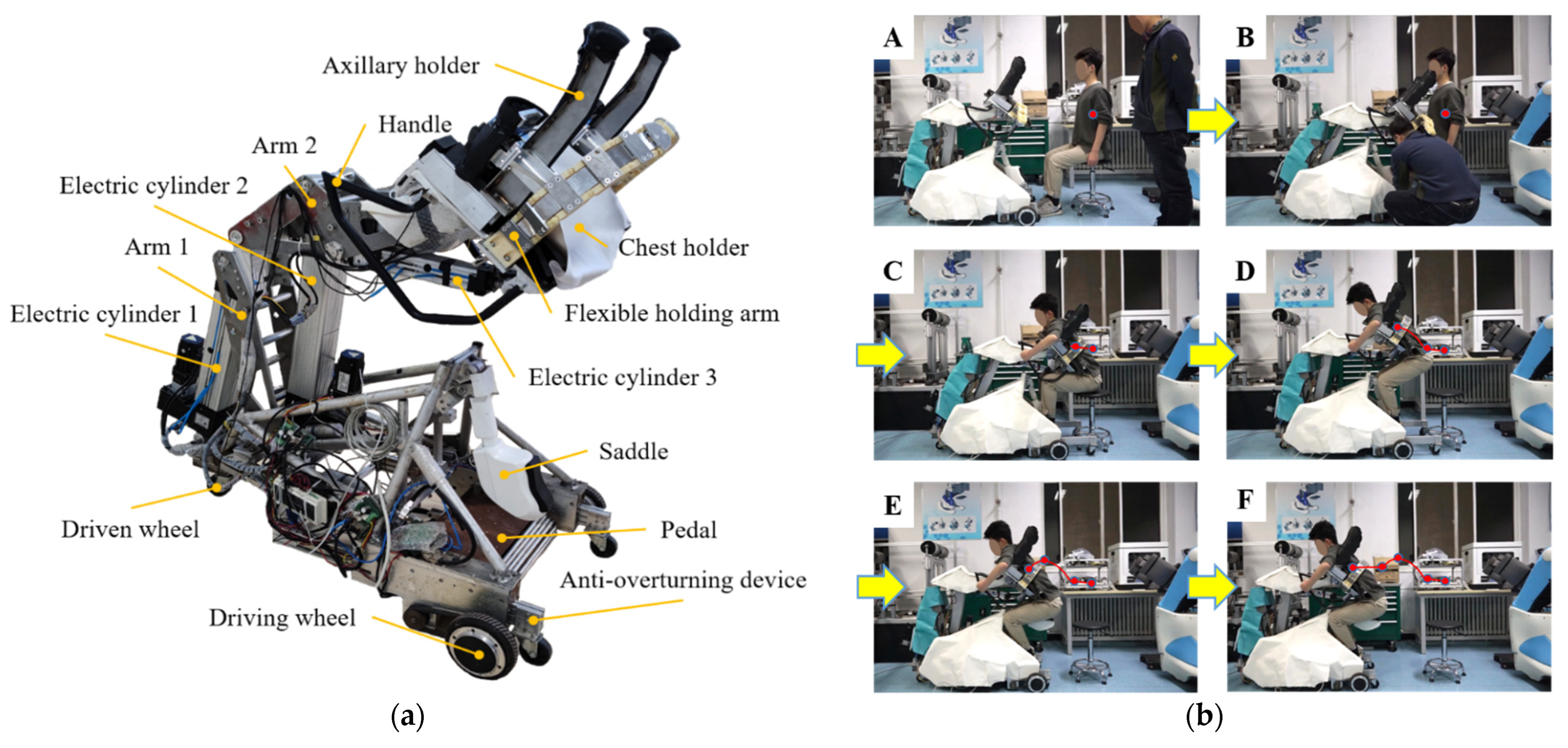
To achieve a comfortable and safe patient transfer and a convenient operation for caregivers, we developed a piggyback transfer robot [18] by imitating the motion when a person holds another person on his/her back. It has a flexible and simple carrying mechanism and is shown in Figure 1a. The robot consists of a chest holder with 3 DOFs (Degree Of Freedom) that can lift and move like a human back. A hip support was also designed that could automatically rise to support the hip of the care-receiver when the robot moved after holding up the care-receiver. Figure 1b presents the process when the robot lifts a subject from a seat to the saddle of the robot and moves. Before the lifting process, the robot approached the subject who was on a seat and adjusted the posture of the chest holder to approach and contact with the subject. A caregiver helped the subject put their feet on the pedal of the robot. The flexible arms of the robot held the subject’s torso. The lifting motion was a movement of lifting the subject from a seat to the saddle of the robot. In moving, the saddle of the robot rose, and the subject’s posture did not change. The trajectory of the marker on the subject also represents the process of the robot lifting and moving. The process of putting a subject down on a bed or other positions is the reverse process of Figure 1b. In addition, an active stiffness control approach [19], in combination with a passive cushion, was proposed and introduced to the robot. The approach adjusted the motion of the chest holder according to the force acting on the care-receiver’s chest to achieve a comfortable lift. The test result demonstrated that the robot could hold a care-receiver from a seat to a bed comfortably.
Most transfer devices still require frequent caregiver operations to realize the comfort lift for different care-receivers [20,21,22]. Each care-receiver needs different lift trajectories to ensure their comfort in transferring since they all have different physical parameters, such as height, weight, and so on. Therefore, the caregiver needs many trials to conduct a comfortable lift for a care-receiver. It takes a lot of time, and the uncertainty of the field operation can easily cause discomfort to the care-receiver. In our previous study, the basic lifting motion of the piggyback nursing-care robot was created by interpolating several comfort postures. These postures were determined based on the opinions of the lifted person. Different care-receivers need different basic motions, so a test based on the subjective evaluation is necessary before designing the basic motion. This way provides a comfortable motion trajectory for each lifted person. However, it also takes a lot of time to design the motion for each care-receiver before lifting.
To solve the problems mentioned above, we present a trajectory design method for the lift motion of the piggyback nursing-care robot. According to the weight and height of the care-receiver, the method calculates a trajectory to conduct a comfort lift. The factors that affect the comfort of the care-receiver were analyzed, and a human-robot mechanics model was built. The subjective evaluation, test results of 20 subjects, and BP neural network were used to build the relationship between comfort force parameters of the human-robot mechanics model and the care-receiver’s weight and height. In addition, the trajectory design method was optimized. The results of three subjects demonstrated that the proposed method could provide a lift trajectory based on the subject’s weight and height. The trajectory can achieve a similar lift as the designed trajectory by relying on the opinion of the subject. This proposed method can be used for the design of the reference trajectory in the piggyback robot compliant control, which can realize the comfortable lifting of the care-receiver.
The paper is organized as follows. Section 2 analyzes the factors that affect the comfort of the care-receiver. Section 3 introduces the human-robot mechanics model and the trajectory design method for the robot lift. Section 4 gives the experimental design, builds the relationship between comfort force parameters of the human-robot mechanics model and the care-receiver’s weight and height, optimizes the trajectory design method, and verifies the feasibility of the motion design method. Section 5 covers the conclusions and gives a brief explanation of future work.

2. The Factors Affecting the Comfort of the Care-Receiver

It is essential to ensure the comfort of the care-receiver. In previous tests, subjective evaluations of subjects [23] demonstrated that forces acting on the care-receiver’s chest and axillaries were the main factors affecting his/her comfort. The uncomfortable posture directly led to pain in the armpits or chest of the subject. The force acting on the chest or armpits exceeded the limits which the subject could accept, and was the cause of this phenomenon. The subject’s armpits were so sensitive that the excessive force acting on the armpits could easily lead to numbness and even pain in the armpits. The excessive force acting on the chest also caused the discomfort of the abdomen and chest.
To clarify the relationship between the force acting on the care-receiver and the posture of the chest holder, an experiment was conducted. In this experiment, the subject was lifted from a seat to the saddle of the robot. The force acting on the subject and the postures of chest holder were recorded when they were lifted. The hip of the subject was not supported in this process. As shown in Figure 2, the VICON motion capture [24] recorded the actual posture of the chest holder. The force acting on the armpit and chest of the subject were measured by using the one-dimensional force sensor and the TEKSCAN tactile sensor [25], respectively. AMIT force plates measured forces acting on the foot of the subject. The times of the collected information were synchronized. In addition, the lift trajectory of the robot was created by interpolating the several postures determined, based on the opinions of the lifted person before the experiment. This motion trajectory can lift the subject comfortably.
Ten healthy subjects participated and they signed written informed consents prior to the experiment. These subjects were adults aged 26–32, including 4 women and 6 men. Their BMI ranged from 17.48–27.57 kg/m2. The experimental results showed that there was the similar feature in relationship between the force acting on the subject and the posture of the chest holder in lifting. A result of subject 6 (1730 mm, 58 kg), as an example, is shown in Figure 3. The force acting on the subject is changed with the postures of the chest holder. The lifting motion of the robot consists of the motions in horizontal distance, vertical distance, and the rotation. To clarity the effect of the lifting motion on the force acting on the subject, these motions in a single DOF are shown in Figure 3b.
In the early stages of lifting, the angle of the chest holder was obviously reduced to ensure the subject could be lifted comfortably. The subject’s torso leaned forward, and there was a significant increase in the force acting on the chest. In contrast, the force acting on axillaries and the force in vertical acting on the foot decreased. After this stage, there were not obvious changes in these forces compared to the early lifting. During the entire lifting, the angle of the chest holder directly affected the force acting on the subject. The force exerted on the chest increased as the angle between the chest holder and the ground decreased. The trend of the force acting on the foot in vertical was opposite to that of the chest since more force was supported by the chest. Compared to the chest and the foot, the armpit took a small part of the force acting on the subject. The trend of the force acting on armpits were also opposite to that of the chest. The force decreased with decreasing the angle of the chest holder. According to the previous test, it was found that forces acting on the care-receiver’s chest and axillaries were the main factors affecting his/her comfort. The experimental results demonstrated that the force exerted on the subject changed with the posture of the chest holder of the robot. Therefore, it is clear that the force change with the posture of the chest holder of the robot is what affects the comfort of the care-receiver.

3. A Human-Robot Mechanics Model and the Motion Design

3.1. A Human-Robot Mechanics Model

To clarify the relationship between the force acting on the subject and the posture of the chest holder, a human-robot mechanics model was built, as shown in Figure 4. In this model, the chest holder of the robot lifted a person from a seat. The person was regarded as a four-link model to simplify this model. In lifting, the chest, including the thorax and the abdomen, of the care-receiver was supported by the chest holder. The thorax and the abdomen were regarded as a whole, including the head and the neck. The pelvis and thigh were seen as a link. The calf and the foot were regarded as the other two links. Each link was articulated with each other. There were interaction forces in the joints of the links.
In lifting, the care-receiver’s chest, armpits, and foot are acting on some forces generated by their own gravity. Interaction forces also exist between the joints of the person. The piggyback nursing-care robot can lift a person with lower limb disability. Their arms are healthy, and they can hold the handle of the robot to ensure their posture in lifting. The grip of hands will reduce the force acting on the body. It is the internal force generated by muscles and different from the force acting on the body. To simplify the mechanics model and influence of the grip, the arms of the person and its weight were ignored in this model. The force acting on the armpits and the friction acting on the chest were regarded as a force. It was noted that there was no relative movement between the care-receiver and the chest holder of the robot in lifting, since the axillary holders of the robot supported the armpits of the care-receiver. Thus, the friction acting on the chest has little effect on the other force acting on the body and can be ignored. The force acting on the chest and foot of the care-receiver were regarded as a combination of force and moment, since they were in the area of contact with each other between the care-receiver and the robot. The size and force of the model are shown in Figure 5a. The position and posture of the chest holder are represented by ( x , y , α ) , where x is the horizontal distance between the joint of the chest holder and the origin of the world frame, y is the vertical distance between the chest holder’s joint and the origin of the world frame, and α is the angle between the chest holder and the ground.
A fast lifting speed of the robot can increase the mental and physical burden on the care-receiver. To ensure the comfort of the person, the lift motion has a slow speed and a small acceleration. Therefore, the effect of inertial force acting on the person was ignored. The lifting motion was analyzed by using the statics analysis. According to the balance of forces and torques, the forces and torques acting on the foot meet:
{ F p x + F 10 x = 0 F p y + F 10 y G 0 = 0 M p + G 0 l 02 = 0 ,
where G 0 is the weight of the foot. F p x and F p y are the friction and pressure exerted on the foot. M p is the torque acting on the foot. F 10 x , F 10 y are the relative forces from calf to the foot. l 02 represents the position of the mass center of the foot. The forces and torques acting on the calf meet:
{ F 21 x F 01 x = 0 F 21 y G 1 F 01 y = 0 G 1 l 12 sin ( π θ 1 ) + F 01 x l 1 sin ( π θ 1 ) + F 01 y l 1 cos ( π θ 1 ) = 0 ,
where G 1 is the weight of foot. F 01 x , F 01 y are the relative forces from the foot to the calf. F 21 x , F 21 y are the relative forces from thigh and pelvis to the calf. θ 1 is the angle between the calf and the ground. l 1 is the length of the calf. l 12 represents its position of barycenter. The forces and torques acting on the thigh and the pelvis meet:
{ F 32 x F 12 x = 0 F 32 y G 2 F 12 y = 0 G 2 l 22 cos θ 2 + F 12 x l 2 sin θ 2 + F 12 y l 2 cos θ 2 = 0 ,
where G 2 is the weight of thigh and pelvis.   F 12 x , F 12 y are the relative forces from the calf to the thigh. F 32 x , F 32 y are the relative forces from the abdomen to the pelvis. θ 2 is the angle between the thigh and the ground. l 2 is the length of the thigh and the pelvis. l 22 represents its position of the barycenter. The forces and torques acting on the torso (head, neck, chest, and abdomen) meet:
{ F c cos ( π 2 α ) F a cos α = F 23 x F c sin ( π 2 α ) F a sin α = G 3 + F 23 y M c + F 23 x l 3 a sin α + F 23 y l 3 a cos α = 0 ,
where G 3 is the weight of torso. F 23 x , F 23 y are the relative forces from the pelvis to abdomen. θ 3 is the angle between the torso and the ground. It is equal to ( π α ). l 3 is the length of torso. l 31 represents its position of the barycenter. F c and M c are the force and torque acting on the chest (thorax and abdomen) of the care-receiver. The friction acting on the chest is not considered, because there is no relative movement between the chest and the chest-holder under the supporting of the axillary support. F a is the force acting on the axillaries.
According to the Formulas (1)–(4) and the geometric relationship of the robot mechanism, the posture of the chest holder ( x c i , y c i , α c i ) is:
{ x c i = d x l 1 cos ( π θ 1 ) + l 2 cos θ 2 b 2 sin α ( l 3 b 1 ) cos α y c i = d y + l 1 sin ( π θ 1 ) + l 2 sin θ 2 + ( l 3 b 1 ) cos α b 2 sin α α c i = arcsin ( F a ( F c 2 F 23 x 2 + F a ) F 23 x F c F 23 x 2 + F a ) ,
where x c i is the horizontal distance between the joint of the chest holder and the origin of the coordinate system, y c i is the vertical distance between the chest holder’s joint and the origin of the coordinate system, and α c i is the angle between the chest holder and the ground. ( d x , d y ) is the position of the ankle joint of the care-receiver. ( d x , d y ) does not change with different care-receivers, since each care-receiver put his/her foot on the same position in lifting. All parameters of the model are shown in Table 1 [26,27].

3.2. The Motion Design

The process of the care-receiver being lifted from a seat to the saddle of the robot can be divided into 4 stages by 5 moments, including the beginning of lifting, rising, falling, and putting on the saddle. These 5 moments consist of a start of lifting, the middle in rising, the highest position in lifting, the middle in falling, and the end of lifting. The position of the mass center of the care-receiver’s torso is marked and the trajectory of the mass center is shown in Figure 6.
According to the planning of the lift motion, the lifting trajectory was determined by five postures. A well-planned and smooth motion trajectory is the key to realizing that the robot can lift a care-receiver flexibly. The sudden change in the speed of robot motion can cause the discomfort to the care-receiver. The cubic Hermite interpolation [28,29] was introduced to the creation of the lift trajectory to ensure the continuum of motion speed at different interpolation positions. Five positions were chosen and interpolated. The position of the chest holder ( x c i , y c i , α c i ) is represented by C i , where i = 0 ,   1 ,   2 ,   3 ,   4 . These positions of the chest holder, including C 0 , C 1 , C 2 , C 3 , and C 4 , are shown in Figure 7. Except for the motion time of lifting, the definition of the interpolation positions is significant to obtain the lift trajectory of the chest holder. The position represents certain specific postures in lifting and ensures the comfort of the care-receiver in this posture. These positions are determined by the Formula (5) and the force that can ensure the care- receiver’s comfort in these postures. The determination method of the force is described in Section 4.2 of this paper.
The lift trajectory of the chest holder, determined by interpolation based on 5 positions, consists of 4 parts. Each part can be determined based on the position of the start and end of each part. The part of the lift trajectory is represented by ( x c ( t ) , y c ( t ) , α c ( t ) ) , where t is the time in lifting, the x c ( t ) is the horizontal distance between the joint of the chest holder and the origin of the coordinate system, y c ( t ) is the vertical distance between the chest holder’s joint and the origin of the coordinate system, and α c ( t ) is the angle between the chest holder and the ground. The lift trajectory of the chest holder is:
{ x c ( t ) = a x + b x t + c x t 2 + d x t 3 y c ( t ) = a y + b y t + c y t 2 + d y t 3 α c ( t ) = a α + b α t + c α t 2 + d α t 3 ,
where a x , b x , c x , d x , a y , b y , c y , d y , a α , b α , c α , d α are parameters of the Formula (6). These parameters can be represented by:
a x = x c ( 𝑖 + 1 ) b x = x c ( 𝑖 + 1 ) ˙ c x = x c ( 𝑖 + 1 ) ˙ x c 𝑖 ˙ 2 t 𝑖 + 1 t 𝑖 3 2 2 x c ( 𝑖 + 1 ) ˙ t 𝑖 + 1 t 𝑖 + x c ( 𝑖 + 1 ) ˙ x c 𝑖 ˙ t 𝑖 + 1 t 𝑖 2 x c ( 𝑖 + 1 ) x c 𝑖 t 𝑖 + 1 t 𝑖 2 d x = 2 x c ( 𝑖 + 1 ) ˙ t 𝑖 + 1 t 𝑖 2 + x c ( 𝑖 + 1 ) ˙ x c 𝑖 ˙ t 𝑖 + 1 t 𝑖 2 2 x c ( 𝑖 + 1 ) x c 𝑖 t 𝑖 + 1 t 𝑖 3
a y = y c ( 𝑖 + 1 ) b y = y c ( 𝑖 + 1 ) ˙ c y = y c ( 𝑖 + 1 ) ˙ y c 𝑖 ˙ 2 t 𝑖 + 1 t 𝑖 3 2 2 y c ( 𝑖 + 1 ) ˙ t 𝑖 + 1 t 𝑖 + y c ( 𝑖 + 1 ) ˙ y c 𝑖 ˙ t 𝑖 + 1 t 𝑖 2 y c ( 𝑖 + 1 ) y c 𝑖 t 𝑖 + 1 t 𝑖 2 d y = 2 y c ( 𝑖 + 1 ) ˙ t 𝑖 + 1 t 𝑖 2 + y c ( 𝑖 + 1 ) ˙ y c 𝑖 ˙ t 𝑖 + 1 t 𝑖 2 2 y c ( 𝑖 + 1 ) y c 𝑖 t 𝑖 + 1 t 𝑖 3
a α = α c ( 𝑖 + 1 ) b α = α c ( 𝑖 + 1 ) ˙ c α = α c ( 𝑖 + 1 ) ˙ α c 𝑖 ˙ 2 t 𝑖 + 1 t 𝑖 3 2 2 α c ( 𝑖 + 1 ) ˙ t 𝑖 + 1 t 𝑖 + α c ( 𝑖 + 1 ) ˙ α c 𝑖 ˙ t 𝑖 + 1 t 𝑖 2 α c ( 𝑖 + 1 ) α c 𝑖 t 𝑖 + 1 t 𝑖 2 d α = 2 α c ( 𝑖 + 1 ) ˙ t 𝑖 + 1 t 𝑖 2 + α c ( 𝑖 + 1 ) ˙ α c 𝑖 ˙ t 𝑖 + 1 t 𝑖 2 2 α c ( 𝑖 + 1 ) α c 𝑖 t 𝑖 + 1 t 𝑖 3
where x c 𝑖 ˙ , y c 𝑖 ˙ , α c 𝑖 ˙ , x c ( 𝑖 + 1 ) ˙ , y c ( 𝑖 + 1 ) ˙ , α c ( 𝑖 + 1 ) ˙ are the velocity at the current moment. Each part of the lift trajectory can be determined by the Formulas (6)–(9). These parts of the trajectory form the whole lift trajectory. Moreover, the velocity at the connection position of each part is continuous.
According to the force analysis of the care-receiver in lifting, the relationship among the posture of the chest holder, the posture of the care-receiver, and the force acting on the care-receiver is clarified. The force is the main factor affecting the comfort of the care-receiver. When the care-receiver is in a comfortable posture, the force is acceptable and corresponds to the comfort state. Differences in physical parameters of the care-receiver, such as height and weight, need be considered since the nursing-care robot need to provide lift to different persons. The relationship among the physical parameters of the care-receiver, the force acting on the care-receiver, and the posture of the chest holder can be represented by:
( C i ,   M F ) = f ( l , G ) ,
where M F = { F a ,   F c ,   F p x ,   F p y } is the force acting on the care-receiver when he/she is lifted comfortably. The force changes with the physical parameters, including the weight G and height l , of the care-receiver. According to the experiment result of the subject, the relationship between the physical parameters and force was determined, as shown in Section 4.2. C i ( i = 0 ~ 4 ) is the selected position of the chest holder, which can ensure the comfort of the care-receiver. It is determined by the Formula (5) and M F . The lift trajectory is created by interpolating the position C i ( i = 0 ~ 4 ) . It can be represented by:
g ( C i ,   t ) = j ( l , G , t ) ,
where g ( C i ,   t ) represents the functional relationship between the interpolation position and the robot motion trajectory, and is obtained by the Formulas (6)–(9). j ( l , G , t ) represents the relationship between the physical parameters of care-receiver and the robot trajectory. g ( C i ,   t ) and j ( l , G , t ) are both functions with time t as the independent variable. The time can be set according to actual requirements.
It is noted in the lift process of the designed trajectory that the robot lifted the care-receiver from a seat to the saddle of the robot. In this process, the hip of the care-receiver is not supported. The lift trajectory is not affected by the starting posture of the care-receiver. In nursing, the care-receiver has a different start posture depending on the care scene. The start posture can be measured by the vision of the robot. A continuous motion trajectory can be obtained by interpolating this posture with the lift trajectory. The hip of the care-receiver is not supported at the end of the trajectory. During the actual robot transfer process, the saddle of the robot will rise and support the care-receiver when the lifting motion is nearly over. It reduces the force acting on the chest and armpits of the care-receiver in moving.

4. Experiment

To improve the accuracy of the model, determine the force parameters of the mechanics model, and verify the feasibility of the trajectory design method, several experiments were conducted. Experimental results of 20 subjects were used to improve model accuracy and determine model parameters. The experimental results of the other three subjects were used to verify the feasibility of the trajectory calculation method. All subjects, who participated in these tests, were in good health and signed written informed consents prior to the experiment.

4.1. Optimization of the Model

The force acting on the care-receiver is only the most important factor affecting comfort. The care-receiver’s comfort is a comprehensive evaluation index. Many other factors can also have an impact on it, such as the force of holding the handle (grip), stretching of the care-receiver’s muscles, speed of the robot, and so on.
The mechanics model built in Section 3.1 is inaccurate. Only the main forces acting on the care-receiver (including the force acting on the chest, the armpits, and the foot) were considered. The grip of hands and the friction acting on the chest were ignored to simplify this model. Therefore, the compensation parameter should be introduced to improve the accuracy of the model. The posture of the chest holder could be represented by the ( x c , y c , α c ) . The compensation parameters λ i , μ , δ were used to optimize the posture of the chest holder to improve the accuracy of the lift trajectory. These parameters were determined by actual test results of the 20 subjects. These subjects were adults aged 26–29, including 4 women and 16 men. Their height ranged from 1650 mm to 1820 mm and their weight ranged from 58 kg to 83 kg. In the test, the reasonable posture of the chest holder, which was used to design the comfort motion, was determined based on these subjects’ opinions and recorded by using the motion capture. The forces acting on the subject in these postures were also recorded. The calculated postures were obtained by using these forces. The compensation parameters λ i , μ , δ were determined by comparing the calculated posture and the posture based on the subject’s opinion. These parameters are the average of the test results. The compensation parameters at different times are listed in Table 2.
Table 2 shows that the parameter δ, which is used to optimize the angle of chest holder, is close to the constant value. The parameter λ and μ, which are used to optimize the displacement of the chest holder, change with time. It is the result of the change in grip and the internal force of human joints with the posture. These parameters are fitted at different times, and the results are presented in Table 3.
The optimized posture is:
{ x r i = λ x c i y r i = μ y c i α r i = α c i + δ ,
where ( x r i ,   y r i ,   α r i ) is the posture after compensation. They are directly introduced into Equation (6) and replace ( x c i ,   y c i ,   α c i ) to obtain the motion trajectory of the robot.

4.2. Neural Network-Based Parameter Determination

These forces F c , F a , F p x ,   F p y , are necessary to calculate the lift trajectory by using the proposed method. These forces are different for each care-receiver, because they have different physical characteristics, such as weight and height. The relationship between the physical parameters and the forces making the subject comfortable is significant to improving the generalizability of the trajectory design method. The BP (Back Propagation) neural network [30,31], which is a highly complex and nonlinear dynamic analysis system, is always used to deal with nonlinear relationships between parameters directly. Therefore, the relationship between the physical characteristics and the forces making the subject comfortable was established by using the BP neural network. In this network, the weight and height were regarded as the input of the network. The forces acting on the chest, armpits, and foot of the subject were regarded as the output of the network. This network will give five sets of forces, which correspond to the five postures of the chest holder making the subject comfortable during lifting. Twenty subjects participated in this test to establish the relationship between the physical parameters and the comfortable force. These subjects also participated in the test for the optimization of the trajectory design method. As a result of the height, weight, gender, and other factors of the subject, each subject’s feelings about the comfort lift was different. According to the analysis of the test results, it was known that the gender of the subjects had no obvious effect on the difference in comfort. Therefore, the parameters of the subjects’ height and weight were selected as the input of the network. In the test, their weight, height, the comfort posture obtained based on the subject’s opinion, and the force in these postures were recorded. The postures making the subject comfortable were determined by considering their subjective feelings. The data of 16 subjects were used as the training set of the network, 2 subjects were used as the test sets of the network, and 2 subjects were used as the validation sets of the network.

4.3. Trajectory Verification

To verify the feasibility of the trajectory calculation method, three subjects (see Table 4) participated in this experiment. These comfort force parameters of subjects obtained by using the prediction network were presented in Table 5.
The experiment focused on lifting a subject from a seat to the saddle of the robot with lift trajectories obtained by the subject’s subjective opinion and the proposed method, respectively. The time of each lifting test was set to be 26 s. In this experiment, all subjects were asked not to use their lower limbs so that we could understand the real feelings when their whole body was lifted. In addition, the subjects were asked to have had enough rest and to have fasted within two hours before the experiment. The motion trajectory of the chest holder, as well as the force acting on the chest, armpits, and foot of the subject were recorded in each test.
Figure 8 shows the posture differences of the chest holder in different lift trajectories. The lift motion of the chest holder consists of the rotation, horizontal movement, and vertical movement. It is found that the motion trends in each degree of freedom direction obtained by the two ways are consistent. It demonstrated that the trajectory obtained by the proposed method has the same motion trend as the trajectory obtained based on the subjective feelings of the subject.
To clarify the deviation between the two trajectories, their average deviation was calculated. In this calculation, the trajectory obtained based on subjective evaluation was regarded as the reference. The deviation between two trajectories reflects the accuracy of the proposed method. The proportion of the average deviation from the reference trajectory is presented in Table 6. It shows that the results of subject 1 and subject 2 have a small deviation, and deviations of all items are within 10%. The result of subject 3, especially in the results of angle and vertical displacement, has a relatively large deviation, which is controlled by 15%. In summary, the accuracy of the proposed method reaches 85%. Therefore, this method is feasible for designing the lifting trajectory of the robot.
The large deviation of subject 3 was caused by the lack of samples with similar characteristics in establishing the relationship between the physical characteristics and the forces making the subject comfortable. This problem can be solved by adding samples with different characteristics.
In lifting, the main factor affecting the comfort of the care-receiver is the force acting on the care-receiver. It is necessary to verify the force acting on subjects in different trajectories. These forces consist of the force acting on the chest, the armpits, and the foot. The combined (resultant) force of these forces is essentially equal to the subject’s gravity. They influence each other and correspond to each other in different postures of the subject. Each of these forces can reflect the change in the comfort state of the care-receiver. It should be noted that the grip of the hand affected other forces acting on the care-receiver in lifting. Due to the small contact area between the care-receiver’s armpits and the chest holder in lifting, the armpits of the subject could not bear excessive force. This force was easily affected by the other forces, such as the grip of the hands and the muscle force. It was difficult to judge the comfort state. Therefore, the force acting on the chest was used to judge the comfort state of the subject. The force acting on the chest of three subjects in different trajectories are shown in Figure 9.
Figure 9 shows that the force has the same trend in different trajectories, although there is a small deviation between the two trajectories. To clarify the specific deviation, their average was also calculated, and the force in the trajectory obtained based on subjective evaluation was regarded as the reference. The proportion of the average deviation from the reference is presented in Table 7. It shows that the results of subject 1 and subject 2 have a small deviation, and deviations of all items are within 10%. The result of subject 3 has a relatively large deviation, which is also about 15%. It is the result of the lift trajectories calculated by the proposed method.
The comparison of the trajectory obtained by the two methods demonstrated that the motion trajectory obtained by the proposed trajectory design method could lift a care-receiver and basically ensure the comfort of the care-receiver. Although there was a deviation between the trajectory designed by the method and the trajectory obtained by the subjective feelings, this designed trajectory can be used as a reference trajectory for the robot lifting motion. The robot developed by our team can actively adjust the posture of the chest holder to lift a care-receiver comfortably. Before the lifting task, the lift trajectory ensuring the care-receiver’s comfort can be obtained quickly, based on the weight and height of the care-receiver. The trajectory will be input to the robot in advance as a preset value. The robot adjusts the posture of the chest holder according to the force acting on the chest of the care-receiver in lifting while using this trajectory. Therefore, the proposed method is effective for improving the operational efficiency of the robot.

5. Conclusions

To quickly obtain a lift trajectory for a piggyback nursing-care robot, a method was proposed. This piggyback nursing-care robot, which can lift and move a person from a wheelchair to a bed or a pedestal pan like a person holding another person on his/her back, has been developed. The proposed method can quickly provide a lift trajectory based on weight and height of the care-receiver. The trajectory can make the robot conduct a comfort lift for the care-receiver. A human-robot mechanics model and the relationship between the comfort lift trajectory and the care-receiver’s weight and height were contributed. According to the test results of 20 subjects, the force parameters used for trajectory design were determined, and the trajectory design method was optimized.
The results of three subjects demonstrated that the trajectory obtained by the proposed method has a similar motion trend and force as the trajectory obtained. The average deviation of trajectory and force between the trajectory obtained by the method, and the trajectory designed based on the subject’s opinion, were within 15% of the trajectory designed based on the subject’s opinion. This method can conveniently and quickly provide a robot lift trajectory based on the subject’s weight and height, and this trajectory. It can be used for the design of the reference trajectory in the piggyback robot compliant control, which can realize the comfortable lifting of the care-receiver.
In the future, the authors’ team will increase the number of subjects and optimize the mechanics model, to improve the accuracy of the trajectory designed. In addition, the comfort of the care-receiver is significant to the development of the nursing-care robot. Further study on the quantitative evaluation of the care-receiver’s comfort will be conducted. These will contribute to improving the comfort of the nursing-care robots.

Author Contributions

Data curation, Y.L. and C.S.; formal analysis, S.G.; investigation, Y.L., Z.J. and C.S.; methodology, Y.L., Z.J. and S.G.; project administration, S.G.; software, Y.L., Z.J. and C.S.; supervision, J.N.; validation, Y.L.; writing—original draft, Y.L.; writing—review and editing, Y.L. All authors have read and agreed to the published version of the manuscript.

Funding

The work presented in this paper was supported by the Shanghai Science and Technology Program (21511101701), and the Key Research and Development Plan of Hebei Province (19211817D).

Institutional Review Board Statement

The study was conducted in accordance with the Declaration of Helsinki, and approved by the Ethics Committee of the 983 Hospital in Tianjin (protocol code 2019-019-02 and date of approval 22 October 2019).

Informed Consent Statement

Written informed consent has been obtained from the subjects to publish this paper.

Data Availability Statement

The datasets generated and supporting the findings of this article are obtainable from the corresponding author upon reasonable request. The authors attest that all data for this study are included in the paper.

Acknowledgments

The authors are grateful to the anonymous reviewers and the Editor for their valuable comments and suggestions on improving this paper.

Conflicts of Interest

The authors declare no conflict of interest.

References

  1. Tagliavini, L.; Botta, A.; Cavallone, P.; Carbonari, L.; Quaglia, G. On the suspension design of paquitop, a novel service robot for home assistance applications. Machines 2021, 9, 52. [Google Scholar] [CrossRef]
  2. Riley, P.O.; Krebs, D.E.; Popat, R.A. Biomechanical analysis of failed sit-to-stand. IEEE Trans. Rehabil. Eng. 1997, 5, 353–359. [Google Scholar] [CrossRef] [PubMed]
  3. Tian, Y.; Wang, H.; Niu, B.; Zhang, Y.; Du, J.; Niu, J.; Sun, L. Mechanical design and analysis of the end-effector finger rehabilitation robot (EFRR) for stroke patients. Machines 2021, 9, 110. [Google Scholar] [CrossRef]
  4. Zsiga, K.; Tóth, A.; Pilissy, T.; Péter, O.; Dénes, Z.; Fazekas, G. Evaluation of a companion robot based on field tests with single older adults in their homes. Assist. Technol. 2018, 30, 259–266. [Google Scholar] [CrossRef] [PubMed]
  5. Sefcik, J.S.; Johnson, M.J.; Yim, M.; Lau, T.; Vivio, N.; Mucchiani, C.; Cacchione, P.Z. Stakeholders’ perceptions sought to inform the development of a low-cost mobile robot for older adults: A qualitative descriptive study. Clin. Nurs. Res. 2017, 27, 61–80. [Google Scholar] [CrossRef] [PubMed]
  6. Allison, B.; Nejat, G.; Kao, E. The design of an expressive humanlike socially assistive robot. ASME J. Mech. Rob. 2008, 1, 011001. [Google Scholar] [CrossRef]
  7. Greenhalgh, M.; Landis, J.M.; Brown, J.; Kulich, H.; Bass, S.; Alqahtani, S.; Deepak, N.; Cryzter, T.M.; Grindle, G.C.; Koontz, A.M.; et al. Assessment of usability and task load demand using a robotic assisted transfer device compared to a hoyer advance for dependent wheelchair transfers. Am. J. Phys. Med. Rehabil. 2019, 98, 729–734. [Google Scholar] [CrossRef] [PubMed]
  8. Kume, Y.; Kawakami, H. Development of power-motion assist technology for transfer assist robot. Matsushita Tech. J. 2008, 54, 50–52. [Google Scholar]
  9. Shiraishi, M.; Watanabe, H. Pneumatic assist device for gait restoration. ASME J. Dyn. Syst. Meas. Control. 1996, 118, 9–14. [Google Scholar] [CrossRef]
  10. Ye, A.X.; Zou, W.; Xu, Z.D.; Lu, T.; Yuan, K. Docking control of intelligent wheelchair based on vision. In Proceedings of the 2011 9th World Congress on Intelligent Control and Automation, Taipei, Taiwan, 21–25 June 2011; pp. 214–219. [Google Scholar]
  11. Kakutani, K.; Iwaki, T.; Takaoka, D.; Yamada, M.; Tsukamoto, K. Development of a transfer supporting equipment. In Proceedings of the 1995 IEEE/RSJ International Conference on Intelligent Robots and Systems. Human Robot Interaction and Cooperative Robots, Pittsburgh, PA, USA, 5–9 August 1995; pp. 268–273. [Google Scholar]
  12. Stein, J. Stroke and the Family: A New Guide; Harvard University Press: Cambridge, MA, USA, 2009. [Google Scholar]
  13. Bostelman, R.; Albus, J. Survey of Patient Mobility and Lift Technologies: Toward Advancements and Standards; No. 7384; Intelligent Systems Division, National Institute of Standards and Technology: Gaithersburg, MD, USA, 2006. [Google Scholar]
  14. Mukai, T.; Hirano, S.; Nakashima, H.; Kato, Y.; Sakaida, Y.; Guo, S.J.; Hosoe, S. Development of a nursing-care assistant robot riba that can lift a human in its arms. In Proceedings of the 2010 IEEE/RSJ International Conference on Intelligent Robots and Systems (IROS), Taipei, Taiwan, 18–22 October 2010; pp. 5996–6001. [Google Scholar]
  15. Ding, J.; Lim, Y.J.; Solano, M.; Shadle, K.; Hu, J. Giving patients a lift—The robotic nursing assistant (RoNA). In Proceedings of the 2014 IEEE International Conference on Technologies for Practical Robot. Applications (TePRA), Woburn, MA, USA, 14–15 April 2014; pp. 1–5. [Google Scholar]
  16. Park, D.I.; Kim, H.; Park, C.; Kim, D. Design and analysis of the dual arm manipulator for rescue robot. In Proceedings of the 2017 IEEE International Conference on Advanced Intelligent Mechatronics, Munich, Germany, 3–7 July 2017; pp. 608–612. [Google Scholar]
  17. Schoenfisch, A.L.; Lipscomb, H.J.; Pompeii, L.A.; Myers, D.J.; Dement, J.M. Musculoskeletal injuries among hospital patient care staff before and after implementation of patient lift and transfer equipment. Scand. J. Work Environ. Health 2013, 39, 27–36. [Google Scholar] [CrossRef] [PubMed] [Green Version]
  18. Liu, Y.; Chen, G.; Liu, J.; Guo, S.; Mukai, T. Biomimetic Design of a chest carrying nursing-care robot for transfer task. In Proceedings of the 2018 IEEE International Conference on Robotics and Biomimetics (ROBIO), Kuala Lumpur, Malaysia, 12–15 December 2018; pp. 45–50. [Google Scholar]
  19. Liu, Y.; Guo, S.; Yin, Y.; Jiang, Z.; Liu, T. Design and compliant control of a piggyback transfer robot. ASME J. Mech. Rob. 2022, 14, 031009. [Google Scholar] [CrossRef]
  20. Toyota Motor Co., Ltd. A Patient Transfer Assist Robot. Available online: http://www.toyota.com.cn/technology/robot/robot04.php (accessed on 24 January 2017).
  21. Fuji Machinery Co., Ltd. Mobility Support Robot. FUJI Innovative Spirit. Available online: https://www.fuji.co.jp/en/about/hug/ (accessed on 13 December 2018).
  22. Kawakami, H.; Kume, Y.; Nakamura, T.; Fujioka, S. Transfer Assist Device and Transfer Assist Device with Multi-Supporter Mechanism. U.S. Patent US20100064431A1, 18 March 2010. [Google Scholar]
  23. Liu, Y.; Guo, S.; Chen, G.; Liu, J.; Gan, Z. Bionic motion planning and the analysis for human comfort of a piggyback nursing-care robot for transfer tasks. Chin. J. Mech. Eng. 2020, 56, 147–156. [Google Scholar]
  24. Slr, A.; Rtc, B.; Ckk, A.; Dbl, A.; Pnw, B. Kinematic analysis of gait in an underwater treadmill using land-based vicon t 40 s motion capture cameras arranged externally. J. Biomech. 2021, 124, 110553. [Google Scholar]
  25. Jansson, K.S.; Michalski, M.P.; Smith, S.D.; Laprade, R.F.; Wijdick, C.A. Tekscan pressure sensor output changes in the presence of liquid exposure. J. Biomech. 2013, 46, 612–614. [Google Scholar] [CrossRef] [PubMed]
  26. Tilley, A.; Associates, H.; Körnig, N.; Lampe, M.; Zeeuw, P.D. The measure of man and woman: Human factors in design. In American Scholar; Watson-Guptill Publications: New York, NY, USA, 2002; p. 498. [Google Scholar]
  27. Armstrong, H.G. Anthropometry and mass distribution for human analogues. In Military Male Aviators; Naval Biodynamics Laboratory: New Orleans, LA, USA, 1988. [Google Scholar]
  28. Fan, J. Motion control technology research based on pvt algorithm. Appl. Mech. Mater. 2013, 330, 611–614. [Google Scholar] [CrossRef]
  29. Yue, H.; Chen, W.; Chen, W.; Wu, X. Spline-interpolation based PVT algorithm and application in a bionic cockroach robot. In Proceedings of the International Conference on Control. Automation Robotics & Vision, Singapore, 7–10 December 2010; pp. 1742–1747. [Google Scholar]
  30. Feng, Z.; Li, P.; Hou, Z.G.; Zhen, L.; Chen, Y.; Li, Q.; Min, T. sEMG-based continuous estimation of joint angles of human legs by using bp neural network. Neurocomputing 2012, 78, 139–148. [Google Scholar]
  31. Sadeghi, B. A bp-neural network predictor model for plastic injection molding process. J. Mater. Process. Tech. 2000, 103, 411–416. [Google Scholar] [CrossRef]
Figure 1. The piggyback nursing-care robot [19]: (a) The structure of the robot; (b) The transfer process of the robot.
Machines 10 00441 g001
Figure 2. The measurement when the piggyback nursing-care robot lifted a subject.
Machines 10 00441 g002
Figure 3. The relationship between forces acting on the subject and the posture of the chest holder: (a) the posture of the chest holder; (b) the force acting on the subject.
Machines 10 00441 g003
Figure 4. The human-robot mechanics model.
Machines 10 00441 g004
Figure 5. The size and forces of the model: (a) size of the model; (b) force acting on the model.
Machines 10 00441 g005
Figure 6. The motion planning of the nursing-care robot for the transfer task.
Machines 10 00441 g006
Figure 7. Realization of the motion trajectory for lifting.
Machines 10 00441 g007
Figure 8. The posture of the chest holder in different motions.
Machines 10 00441 g008
Figure 9. The force acting on the chest of three subjects in different motions.
Machines 10 00441 g009
Table 1. The parameters of the model.
(a) Size
Item l 3 l 2 l 1 l 31 l 22 l 12 l 02 l c s b 1 b 1
Value 0.218   l 0.32   l 0.238   l 0.132   l 0.21   l 0.228   l 0.113   l 0.212   l 120 mm43 mm
(b) Weight
Item G 3 G 2 G 1 G 0
Value 0.403   G 0.383   G 0.094   G 0.024   G
l and G are the height and weight of the care-receiver.
Table 2. The compensation parameters for different postures.
PostureTime/s λ μ δ
P 0 00.7891.27521.4
P 1 50.7591.375
P 2 100.7191.45
P 3 180.6791.25
Table 3. The fitted compensation parameters.
ItemParameters
λ 5.8 × 10 3 t + 0.7853
μ 2 × 10 5 t 4 0.6 × 10 3 t 3 + 6.5 × 10 3 t 2 + 1.7 × 10 3 t + 1.275
δ 21.4
Table 4. The subjects.
GenderAgeHeight (mm)Weight (kg)BMI (kg/m2)
Subject 1Male31172764.321.6
Subject 2Male30173668.822.8
Subject 3Female26161045.317.5
Table 5. The comfort force parameters.
PosturesChest (N)Armpits (N)Foot in Horizontal (N)Foot in Horizontal (N)
Subject 10195.6018.0634.31214.09
1214.0918.4222.50180.91
2207.8120.5920.91172.76
3228.2317.3317.79157.58
4224.2819.7814.49166.07
Subject 20183.9920.4532.20236.29
1206.3319.4624.51204.50
2205.5221.4123.84206.32
3223.0618.1319.66191.19
4216.7420.2611.51183.80
Subject 30257.5920.795.6989.09
1259.8915.062.0578.87
2269.5012.652.9776.99
3252.6314.255.44102.50
4239.4416.247.23100.03
Table 6. The average deviation of the trajectory.
α (%)x (%)y (%)
Subject 19.564.763.85
Subject 27.271.863.52
Subject 312.501.4414.31
Table 7. The average deviation of the force.
Chest (%)
Subject 18.49
Subject 25.87
Subject 315.66
Publisher’s Note: MDPI stays neutral with regard to jurisdictional claims in published maps and institutional affiliations.