Article

An Improved Residual-Based Detection Method for Stealthy Anomalies on Mobile Robots

College of Intelligence Science and Technology, National University of Defense Technology, Changsha 410073, China
*
Author to whom correspondence should be addressed.
Machines 2022, 10(6), 446; https://doi.org/10.3390/machines10060446
Submission received: 26 April 2022 / Revised: 31 May 2022 / Accepted: 1 June 2022 / Published: 5 June 2022
(This article belongs to the Section Machines Testing and Maintenance)

Abstract

:
With the expansion of the cyber-physical system (CPS) application area, its importance has become more and more prominent. As one of the typical applications of CPS, the anomaly detections of mobile robots have attracted the attention of all parties. As part of the CPS, mobile robots face the problem that conventional residual-based detection methods cannot identify stealthy anomalies. The conventional residual-based detection methods mainly use the residual signal calculated from the control signal and measure output for detection, which is widely used in fault diagnosis. Still, it is difficult to be useful in deceptive stealthy anomalies purposefully imposed on mobile robots, which are designed to evade the conventional detections by tampering with measure output. Furthermore, they can control the system to deviate from the expected operations, causing degradation of control performance or even damage without being detected. Based on this, by analyzing the system model of CPS and the stealthy conditions of anomalies, the improved residual-based detection method is proposed in this paper. Moreover, three stealthy anomalies purposefully imposed on an omnidirectional mobile robot (OMR) are detected by using the conventional residual-based methods and the improved residual-based method. Finally, the experimental results show that the method proposed can effectively detect the stealthy anomalies purposefully imposed on the OMR.

1. Introduction

In recent years, with the vigorous development of network communication and control technologies, the trend of highly integrating cyberspace and physical objects is becoming more and more obvious. CPS is an intelligent system with highly integrated interaction between computing units and physical objects in a networked environment, supported by the Internet of Things, automatic control and other technologies [1]. As an emerging technology field of the century, CPS involves energy, medicine, transportation, logistics, aerospace and even many other fields, and has become the core technology of the new round of industrial change.
While CPS has brought great convenience and benefits, its increasing openness has also ushered in many challenges and threats due to its growing reliance on technologies such as network communications [2]. Because the information domains of CPS are deeply coupled with the physical domains, cyber-attacks on the system from the network can also penetrate the physical layer, causing serious damage to the physical processes of the system and even security incidents. Thus, anomalies artificially and intentionally imposed on the system can be described as cyber-attacks from another perspective. Correspondingly, stealthy anomalies purposefully imposed on the system can also be described as stealthy cyber-attacks. In recent years, there have been many security incidents against CPS worldwide, which have caused great concern in the world. In 2003, many Web sites and Internet services were rendered inaccessible by the Sapphire (or Slammer) worm responsible for the attack [3]. In 2010, the Stuxnet virus attacked Iran’s nuclear power plant, causing the destruction of its centrifuges and rendering the nuclear reactor inoperable for a long time [4,5]. In 2017, WannaCry attacked the National Health Service, causing huge casualties and economic damage [6]. These show that once an attacker successfully attacks the CPS, it will cause serious damage and spread to all aspects of society, generating huge economic losses and irreversible security incidents.
Among the various cyber-attacks against CPS, integrity attacks are specifically targeted at automatic control systems by injecting attack signals into the input and output channels of the system, causing system performance degradation or even causing security incidents [7,8]. For the detection of integrity attacks, observer-based fault detection techniques are widely accepted and effective [9,10]. However, unlike technical failures, network attacks are artificial and can be designed and generated by attackers. In this case, it is difficult to detect them with known detection methods. Such attacks, which cannot be detected with known detection techniques, are called stealthy [11]. For such stealthy integrity attacks, there have been many studies using observer-based detection methods to detect stealthy integrity attacks such as replay, zero-dynamics, covert attacks, etc. [12,13,14]. However, none of these approaches had a unified observer-based general detection scheme until Ding proposed a unified control and detection framework applied to detect stealthy integrity injection attacks in feedback control systems [15]. Therefore, in this paper, the unified control and detection framework is applied to detect stealthy anomalies purposefully imposed on mobile robots.
The main contributions of this paper can be summarized as follows:
  • To address the problem that normal residual detection methods cannot detect the existence of stealthy anomalies purposefully imposed on mobile robots, this paper proposes to apply an improved residual-based detection method to the anomaly detection of mobile robots.
  • Three ways to achieve stealthy anomalies purposefully imposed on the OMR, zero-dynamic attacks, covert attacks and replay attacks are implemented on the OMR, and their implementation results are analyzed and summarized, then some new conclusions are obtained.
  • The application of the improved residual-based method is implemented on the OMR, and the detection performance of this method can meet the requirements for general anomaly detection.
The rest of the paper is organized as follows. Section 2 demonstrates the system model of CPS and three types of stealthy attacks such as zero-dynamic attacks, covert attacks, and replay attacks. In Section 3, the improved residual-based detection method and implementation process are described. The implementations of three stealthy attacks based on the OMR and the detection experiments of the improved residual-based method are given in Section 4. The conclusions are stated in Section 5.
Remark 1.
In this paper, anomalies artificially and intentionally imposed on the system can be described as cyber-attacks. Correspondingly, stealthy anomalies purposefully imposed on the system can also be described as stealthy cyber-attacks. Moreover, the domain variable z or k may be dropped out when there is no risk of confusion.

2. Materials and Methods

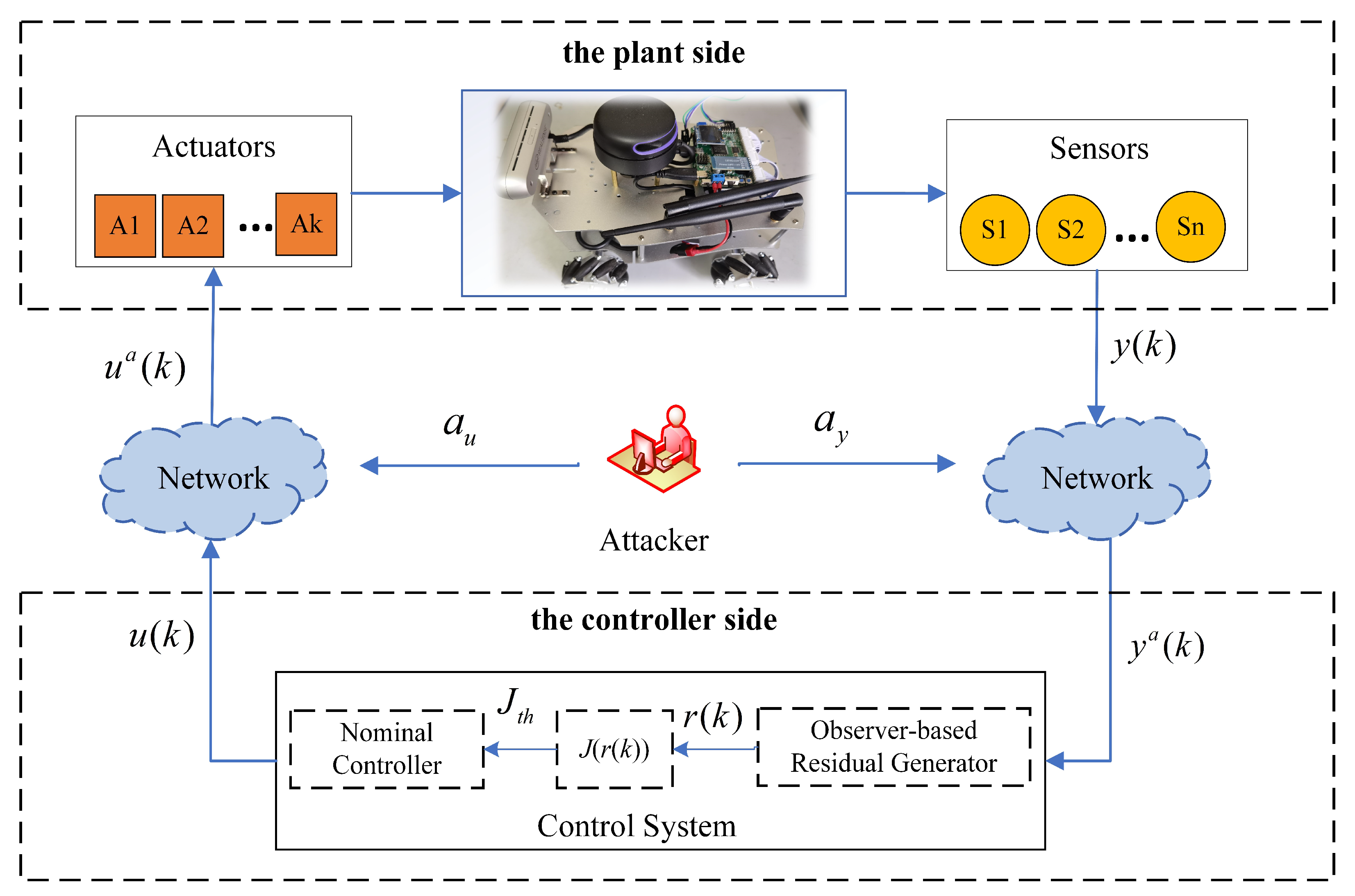
2.1. System Description

In general, in case of an attack, as shown in Figure 1, the CPS discrete state space form is represented as follows.
x ( k + 1 ) = A x ( k ) + B u a ( k ) + w ( k ) , x ( 0 ) = x 0 y a ( k ) = C x ( k ) + D u a ( k ) + a y ( k ) + v ( k )
In addition, considering closed-loop control,
u a ( z ) = K ( z ) y a ( z ) + η ( z ) + a u ( z )
where, x ( k ) R m are the system state variables, x 0 is the initial state of the system. u a ( k ) and y a ( k ) are the actuator input and system output respectively after the system is attacked, a u ( k ) and a y ( k ) are the attack signals on the actuators and sensors respectively. w ( k ) and v ( k ) are the process noise and measurement noise of the system respectively, and satisfy w ( k ) N ( 0 , σ w 2 ) , v ( k ) N ( 0 , σ v 2 ) . The matrices A , B , C , D are real constant matrices of the corresponding dimensions, representing the system model parameters. K ( z ) is the controller parameter, and η ( z ) is the reference signal.
According to [16], K ( z ) can be parameterized by Youla parameterisation in the following form:
K ( z ) = ( X ( z ) Q ( z ) N ^ ( z ) ) 1 ( Y ( z ) + Q ( z ) M ^ ( z ) )
where, Q ( z ) is Youla parameterisation, M ^ z , N ^ z and X z , Y z are coprime pairs, represented by the parameter matrices as follows. The matrix F makes A F ( A F = A + B F ) stable, the matrix L makes A L ( A L = A L C ) stable.
M ^ ( z ) = A L L C I , N ^ ( z ) = A L B L D C D X ( z ) = A L ( B L D ) F I , Y ( z ) = A L L F 0
Considering the observer-based residual generator, the matrix L is chosen to make A L stable. Thus the state space expression of the residual generator can be written in the following form.
x ^ ( k + 1 ) = A x ^ ( k ) + B u ( k ) + L r 0 ( k ) y ^ a ( k ) = C x ^ ( k ) + D u ( k ) r 0 ( k ) = y a ( k ) y ^ a ( k ) .
According to [15], the residual signal r 0 ( z ) can be expressed in the form of coprime pairs as follows.
r 0 ( z ) = M ^ ( z ) y a ( z ) N ^ ( z ) u ( z ) .

2.2. Stealthy Attacks

Whether a cyber-attack is stealthy or not can be determined based on the following Definition 1.
Definition 1.
Given the attack-containing system model (1), w ( k ) = 0 , v ( k ) = 0 , an injection cyber-attack is stealthy if the following equation holds:
u , r 0 ( z ) = y a ( z ) y ^ a ( z ) = 0 .
In the following, zero-dynamic attacks, covert attacks and replay attacks are described respectively according to the definition of stealthy.

2.2.1. Zero-Dynamic Attacks

Zero-dynamic attacks mean that only a u ( z ) attacks the actuators of the plant side, while there are no attacks at the sensors, which finally causes y ( z ) = y a ( z ) during the period of detection, and cannot be detected. The zero-dynamic attacks satisfy the following form:
r 0 ( z ) = N ^ ( z ) M ^ ( z ) u ( z ) + a u ( z ) y a ( z ) = N ^ ( z ) a u ( z ) = 0 .

2.2.2. Covert Attacks

Covert attacks target both actuators and sensors at the plant side. They apply a u ( z ) to the actuators to affect the control performance of the system, while hiding themselves by tampering with data through attacks on the sensors. Therefore, the covert attacks satisfy the following form:
r 0 ( z ) = N ^ ( z ) M ^ ( z ) u ( z ) + a u ( z ) y a ( z ) a y ( z ) = N ^ ( z ) a u ( z ) M ^ ( z ) a y ( z ) = 0 .

2.2.3. Replay Attacks

Replay attacks are mainly performed by accessing the signal transmission channels, attacking the actuators, and recording and re-covering the measurement data of the sensors. The implementation of the replay attacks is: on the sensor side, the measured data in the steady-state of the system are recorded in advance, and the actual measured values are overwritten with the recorded data when the attacks are carried out (i.e., y ( k ) = y ( k τ ) , τ > 0 ); at the same time, on the actuator side, a u ( z ) is designed to influence the control performance of the system. Obviously, in the steady-state of the system, the replay attacks are stealthy.
Remark 2.
Zero-dynamic attacks, covert attacks and replay attacks satisfy the stealthy condition of Definition 1. In addition, zero-dynamic attacks and covert attacks require complete knowledge of the system model to evade the detection mechanism of (5), whereas replay attacks do not, and they are stealthy when the system is stable.

3. Theory and Calculation

From the previous analysis, it is clear that the observer-based residual detector expressed in (5) is not effective in detecting stealthy attacks (e.g., zero-dynamic attacks, covert attacks, replay attacks, et al.). Therefore, when the CPS faces a stealthy attack, a more effective method is needed to detect the attack. This section mainly describes the method of intrusion detection based on the improved residual [15].

3.1. The Construction of Improved Residual Method

From the perspective of preventing attackers from using the data for identification, an encryption strategy acting on control signals is proposed, which makes the data transmitted via the network no longer u ( z ) and y ( z ) .
In the absence of attacks, on the plant side, u ( z ) can be obtained by observer-based feedback control,
x ^ ( z + 1 ) = A x ^ ( z ) + B u ( z ) + L r 0 , p ( z ) u ( z ) = F x ^ ( z ) Q ( z ) r 0 , p ( z ) + η ¯ ( z ) η ¯ ( z ) = ( X ( z ) Q ( z ) N ^ ( z ) ) η ( z ) .
The following transformation is performed to avoid attackers using y ( z ) and u ( z ) directly:
u ( z ) = F x ^ ( z ) + γ ( z ) γ ( z ) = η ¯ ( z ) Q ( z ) r 0 , p ( z ) ,
where, r 0 , p ( z ) is used as a signal transmitted from the plant side to the controller side instead of y ( z ) , and γ ( z ) is used as a signal transmitted from the controller side to the plant side instead of u ( z ) . x ^ ( z ) is observed by setting a state observer on the plant side.
Remark 3.
The positions of the observers in (5) and (10) are different. The observer given in (5) is constructed on the controller side and the observer given in (10) is constructed on the plant side. Therefore, r 0 ( z ) is computed by estimating from u ( z ) and y a ( z ) , r 0 , p ( z ) is computed by estimating from u a ( z ) and y ( z ) .
Referring to (2), (3) and (10), and considering that in the absence of attacks, the following equation holds:
X ( z ) u ( z ) + Y ( z ) y ( z ) γ ( z ) = X ( z ) u ( z ) + Y ( z ) y ( z ) η ¯ ( z ) + Q ( z ) r 0 , p ( z ) = u ( z ) F x ^ ( z ) γ ( z ) = 0 .
Therefore, the detection encryption signal β ( z ) is set in the form shown below:
β ( z ) = u ( z ) F σ x ^ ( z ) u ( z ) F x ^ ( z ) = R σ ( z ) γ ( z ) + Q σ ( z ) r 0 , p ( z ) ,
where F σ is the set of arbitrary state feedback matrices that make A F σ ( A F σ = A + B F σ ) stable, and F is one of them, the following relation exists:
R σ ( z ) = A F B F F σ O , Q σ ( z ) = A F L F F σ O .
The residual signal r β ( z ) is constructed as follows:
r β ( z ) = β ( z ) R σ ( z ) γ ( z ) .
Obviously, according to (13) and (15), when there is no attack,
r β ( z ) = Q σ ( z ) r 0 , p ( z ) .
When there is a stealthy attack,
r β ( z ) = R σ ( z ) X ( z ) a γ ( z ) + Q σ ( z ) r 0 , p ( z ) .
It can be found that stealthy attacks can be effectively detected by r β ( z ) , and the detection process is described in Algorithm 1.
Algorithm 1: Detection Process Based on r β ( z )
(1)
Construct a state observer on the plant side and calculate β ( z ) , r 0 , p ( z ) .
x ^ ( k + 1 ) = A + B F x ^ ( k ) + B γ a ( k ) + L r 0 , p ( k )
where r 0 , p ( z ) and β ( z ) are calculated according to (10) and (13).
(2)
r 0 , p ( z ) and β ( z ) are transmitted from the plant side to the controller side via the network.
β a ( z ) = β ( z ) + a β ( z ) , r 0 , p a ( z ) = r 0 , p ( z ) + a r 0 , p ( z )
(3)
The signals γ ( z ) and r β ( z ) are derived on the controller side by (11) and (15).
(4)
γ ( z ) is transmitted from the controller side to the plant side via the network.
γ a ( z ) = γ ( z ) + a γ ( z )

3.2. Detection Logic and Scheme Realization

In order to achieve the detection of cyber-attacks, the detection logic is set as follows.
J ( r ( k ) ) J t h a t t a c k f r e e J ( r ( k ) ) > J t h a t t a c k e d
where J ( · ) is the residual evaluation function, r ( k ) stands for r 0 ( k ) or r β ( k ) , and J t h is the set threshold value, which is a given upper-bound of false alarm rate α . The relevant definitions are as follows:
J ( r ( k ) ) = r ( k ) p , r ( k ) = r 0 ( k ) o r r β ( k ) J t h = χ 1 α 2 ( m ) .
Therefore, the realization of the detection scheme can be summarized as shown in Figure 2.

4. Results and Discussions

The method for constructing r β ( k ) for detecting stealthy attacks is presented previously to address the problem that stealthy attacks evade the detector based on r 0 ( k ) . To better demonstrate the method, a 4-round omnidirectional mobile robot (OMR) is used for experimental verification, as shown in Figure 3. The OMR has sensor modules such as an RGB-D camera, a single-line LIDAR, and an odometer. It is equipped with two controllers, a Jetson Nano and an STM32 controller, which communicate with each other through the serial ports to transfer data. Ubuntu is installed on the Jetson Nano to run ROS, and the STM32 controller is used to control the motion chassis and collect various sensor information. In practice, it is usually connected to the WIFI of the OMR through another PC to remotely log into the ROS system of the OMR, thus issuing commands on the remote PC to operate the OMR movement and display the motion trajectory. Among them, WIFI uses the IEEE 802.11n wireless transmission standard protocol.
The transmission process of signals is described as follows. The signals are exchanged between the control system and the OMR via WIFI. The control commands are transmitted from the control system to the OMR via the network, thus driving the four motors and enabling the OMR to move as instructed. The sensor signals (i.e., position information of the OMR) are transmitted from the OMR to the control system via the network, which updates the control commands. The frequency of the signal transmission in the OMR is 50 Hz.
The state variables x = x ˙ , y ˙ , θ ˙ T of the OMR are the X-axis and Y-axis travel velocity and rotation angular velocity in the robot coordinate system. The attacker attacks the control commands and sensor data through the WIFI transmission channel. In the experiment, it is assumed that only the odometer of the OMR works properly. Meanwhile, the expected movement strategy of the OMR is to travel in a straight line with a speed of 0.5 m/s. The attacker performs a stealthy attack during the driving process and gets the driving data of the OMR.

4.1. Realization of the Stealthy Attacks

4.1.1. Realization of Zero-Dynamic Attacks

Zero-dynamic attacks directly attack the control voltage of the OMR until the input voltages of motors reach the upper limit, causing motors to be damaged and unable to function properly. In this paper, the target of zero-dynamic attacks is the rotation angular velocity θ ˙ of the OMR.
Recalling (8), zero-dynamic attacks satisfy N ^ ( z ) a u ( z ) = 0 , which is not implemented in engineering well. However, according to [17], they also satisfy a u ( k ) = υ k g , which is generally easy to implement in engineering. Where the system zero υ and the corresponding input-zero direction g can be calculated by solving the following equation:
υ I A B C 0 x 0 g = 0 0
where, x 0 is the initial state of the system for which the input sequence a u ( k ) results in an identically zero output.
In the experiment, x 0 = [ 0 , 0 , 0 ] T , based on the parameters (i.e., A, B and C) of the OMR model, υ and g are obtained according to (20) as follows:
υ = 1.006 g = [ 0.080405739446990 , 0.080405742373845 , 0.080405942390918 , 0.080405939501639 ]
Figure 4 shows the situation when the OMR is subjected to zero-dynamic attacks. The OMR travels forward in a straight line at 0.5 m/s as scheduled. At 3.34 s, zero-dynamic attacks are injected into the OMR, directly attacking the input voltages of four wheels, which is excepted to make the OMR end up uncontrolled and rotate rapidly in place until it stops.
Remark 4.
The variables appearing with subscript c in the legend of Figure 4 all refer to the expected speed issued in the control system, while those without subscript c refer to the actual speed of the OMR. And, the situations are similar in the figures appearing later in the paper.
The input voltages of wheels for the whole process are shown in Figure 4a. From the figure, in the early stage (3.34 s~6.40 s) of zero-dynamic attacks, we can find that a u ( k ) have been hidden in the input voltages of the normal control, which can also be seen in a u ( k ) = υ k g and (21), at this point the attack signal a u ( k ) are very small. At 6.40 s, a u ( k ) cancel out with the input voltages of the normal control, which causes the OMR to stop and start rotating. After that, a u ( k ) start to grow exponentially until the input voltages reach the maximum voltage (the maximum voltage of the OMR is 15 V).
Figure 4b,c show the three state variables (i.e., x ˙ , y ˙ and θ ˙ ) for the actual travel of the OMR. From Figure 4b, it can also be found that the OMR stops at 6.90 s, which corresponds to the input voltages in Figure 4a. Figure 4c also shows that the OMR performed a rapid rotation in place after stopping. Finally, the following summary of the zero-dynamic attacks can be obtained.
Conclusion 1.
Zero-dynamic attacks directly attack the actuators and are always increased by a small margin and remain stealthy in the early stages. By the time attacks have revealed their impact on the control system, the best time to protect against them has been missed. Therefore, a good detection method requires that attacks can be detected before there is a huge impact on the system.

4.1.2. Realization of Covert Attacks

From the understanding of (9), covert attacks, after designing a u ( k ) , accordingly need to design a y ( k ) appropriately to make them evade the general detection mechanism. In the experiment, once attacks are injected into the OMR, attack signals start to take over the OMR, and at the same time return the position information of the OMR driving according to the predetermined control commands to the control system, giving it the illusion that the OMR is still in the normal driving state.
Figure 5 shows the situation when the OMR is subjected to covert attacks. The expected movement of the OMR is divided into four stages: in the first stage, the OMR travels in a straight line at 0.5 m/s for awhile and then stops; in the second stage, it turns left after stopping; in the third stage, it turns right after stopping; in the fourth stage, it travels in a straight line at 0.5 m/s for a short distance and then accelerates to 0.6 m/s and continues to travel in a straight line. Correspondingly, covert attacks are injected into each stage of the OMR, thus causing the OMR to deviate from the expected trajectory. The expected movement of the OMR and the corresponding covert attacks are shown in Table 1.
In Table 1, the OMR is at a stop during the interval of the four stages (e.g., 2.9 s~3.2 s). Combining Figure 5 and Table 1, it can be found that the covert attacks can cause stealthy attacks on the system by designing suitable signals as long as the system model is known, regardless of whether the system is in a stable state or not, which is different from the replay attacks.

4.1.3. Realization of Replay Attacks

According to the principle of replay attacks, their implementation is relatively simple, and the key point is the recording and replay of sensor data in the steady state of the OMR. The situation when the OMR is subjected to replay attacks is shown in Figure 6. In the early stage, a set of stable sensor data of the OMR travelling in a straight line at 0.5 m/s is recorded. During the attack phase, the control system sends commands and expects to control the OMR to travel in a straight line at a speed of 0.5 m/s. Then, replay attacks send the data recorded in advance to the control system, overwriting the actual running data of the OMR, i.e., making the control system believe that the OMR has normally been travelling in a straight line at 0.5 m/s. At the same time, attacks with different effects are injected into the OMR at each of the three time periods to make the OMR deviate from the expected trajectory. The attacks are described in Table 2.
Obviously, the principle of replay attacks is equivalent to constructing a virtual control object in the control system, making it mistakenly believe that it is in normal control. The key to this lies in how to overwrite the received data of the control system without being detected.
By analyzing the principles and implementation results of the above three stealthy attacks, the following conclusion can be obtained, which will help in understanding the detection method introduced in Section 3.
Conclusion 2.
Zero-dynamic attacks, covert attacks, and replay attacks all evade the general detection mechanism by manipulating the sensor data received in the control system. However, because attacks aim to affect the plant, the influence on the u ( k ) received in the plant due to attacks cannot be eliminated. This gives us an insight into the detection of stealthy attacks in terms of determining whether there are anomalies in the control signals of the plant side.

4.2. Analysis of the Detection Results

For stealthy attacks, the previous sections analyzed that they are theoretically stealthy for the detector based on r 0 ( k ) and not for the detector based on r β ( k ) . In the following, two detection methods are experimented and analyzed.

4.2.1. Detection Mechanism

According to the theory of χ 2 detection, the residual evaluation function J r 0 ( k ) and J r β ( k ) are constructed as follows.
J r 0 ( k ) = r 0 T ( k ) Σ r 0 r 0 ( k ) J r β ( k ) = r β T ( k ) Σ r β r β ( k )
where Σ r 0 and Σ r β are the covariance matrices of r 0 ( k ) and r β ( k ) , respectively.
Therefore, the test statistics used for the two detection methods (i.e., based on r 0 ( k ) and based on r β ( k ) ) are expressed as follows.
J 1 ( k ) = J r 0 ( k ) χ 2 ( m ) J 2 ( k ) = J r β ( k ) + J r 0 ( k ) χ 2 ( n )
where J 1 ( k ) is corresponding to the detection method based on r 0 ( k ) and J 2 ( k ) is corresponding to the detection method based on r β ( k ) ; m and n are the corresponding degrees of freedom respectively, where m = 3 (i.e., three state variables), n = 4 (i.e., four control variables).
Set the false alarm rate α = 0.05 , and the corresponding threshold values of J 1 ( k ) and J 2 ( k ) are 7.815 and 9.488 respectively by querying the χ 2 distribution table.

4.2.2. Detection Results

Three stealthy attacks are detected and analyzed based on the aforementioned detection mechanism. The detection results of the three stealthy attacks are shown in Figure 7, Figure 8 and Figure 9, respectively.
For the detection of zero-dynamic attacks, in Figure 7, we can find that the detection method based on r 0 ( k ) basically cannot detect the existence of zero-dynamic attacks either before the OMR stops or when the OMR starts to rotate. It may detect zero-dynamic attacks only when the motors finally fail completely, but at that point it is of little significance. Accordingly, the detection method based on r β ( k ) performs very satisfactorily, detecting zero-dynamic attacks at 6.72 s, which is much more meaningful in practice. Although this method does not immediately detect zero-dynamic attacks at the moment they are injected, it can detect them before they start to affect the normal operation of the OMR, which can also play an early warning role.
Moreover, as seen in Figure 4, the injection of zero-dynamic attacks in the early stage does not have a great impact on the normal operation of the OMR, and its main function in this stage is to take over the actuators stealthily in preparation for the subsequent major attacks on the system. Therefore, it is of practical significance for the method based on r β ( k ) to detect the zero-dynamic attacks before they have a large impact on the system.
For the detection of covert attacks, in Figure 8, we can find that, after injecting covert attacks, the detection method based on r 0 ( k ) does not detect the existence of the attacks at all. In contrast, the detection method based on r β ( k ) can detect the attacks obviously and can detect the attacks continuously with the existence time of the attacks, which will make the covert attacks invisible.
Any one of the four covert attacks (see Table 1) can cause the OMR to deviate from its expected trajectory, but due to the detection of the method based on r β ( k ) , the control system can be aware of the attacks on the OMR in time and thus make preventive as well as rescue measures. Among them, there is a small period before J 2 ( k ) for both turn attacks (i.e., attack #c2 and attack #c3) reach the alarm threshold. This is because the x ˙ , x c ˙ are basically the same when the OMR is turning left and right, and only the y ˙ , y c ˙ and θ ˙ , θ c ˙ are different, see Figure 5. So J 2 ( k ) take a small time to reach the alarm threshold. However, this is enough to prove the effectiveness of the method based on r β ( k ) .
For the detection of replay attacks, in Figure 9, we can find that the method based on r 0 ( k ) does not detect the existence of the attacks at all, which is exactly in line with the stealthy nature of replay attacks. As for the method based on r β ( k ) , it not only detects replay attacks but also tracks them in time. Of course, the prerequisite is that the data of the steady-state of the OMR are recorded in advance, and the control system expects to control the OMR in the same steady-state. Otherwise, when the steady state of the OMR changes, the expected control commands also change, and the attacks can be detected by using the method based on r 0 ( k ) at this time.
Moreover, the method based on r β ( k ) can show the relative size of the attack magnitudes to some extent. For example, for attack #r1 and attack #r2, they cause the effect of making the OMR move flat to the left but at different speeds, i.e., with different attack magnitudes. And by calculating the J 2 ( k ) of the two attacks, it can be found that the J 2 ( k ) of attack #r2, which has a larger speed, is also relatively larger. This feature may be applied in evaluating the attack hazard level in the future.

5. Conclusions

For the problem that three stealthy attacks (i.e., zero-dynamic attacks, covert attacks, replay attacks) based on mobile robots cannot be detected by normal residual signal r 0 ( k ) , this paper introduces an improved residual-based detection method that can achieve the detection of the attacks. First, the stealthy conditions of the three attacks are explained and defined, and their theoretical representations are given. In addition, the improved detection method based on the residual r β ( k ) is introduced, and the implementation process is summarized. Then, the process of implementing the three attacks on OMR and the results are given, and the characteristics of each attack are analyzed and summarized. Finally, based on the χ 2 detection mechanism, the three attacks are detected by using two residual signals, r 0 ( k ) and r β ( k ) . It is found that the detection effect of the improved detection method based on r β ( k ) is consistent with the conclusion given in the theoretical part, which can successfully detect the three stealthy attacks.
Further, after successfully detecting stealthy attacks, the ultimate goal is to maintain the stable operation of the system. Therefore, based on the detection results, how to perform security state estimation and recovery control to ensure that the system can still maintain the normal state after the attacks should be studied, which are the future research directions.

Author Contributions

Conceptualization, L.X. and Z.L.; data curation, B.Y.; formal analysis, L.X.; funding acquisition, Z.L.; methodology, B.Y., L.X. and Z.L.; writing—original draft, B.Y.; writing—review & editing, B.Y., L.X. and Z.L. All authors have read and agreed to the published version of the manuscript.

Funding

This research was funded by the National Key R&D Program of China Under Grant 2016YFB1200600.

Institutional Review Board Statement

Not applicable.

Informed Consent Statement

Not applicable.

Data Availability Statement

Not applicable.

Conflicts of Interest

The authors declare no conflict of interest.

References

  1. Sztipanovits, J.; Koutsoukos, X.; Karsai, G.; Sastry, S.; Tomlin, C.; Damm, W.; Fränzle, M.; Rieger, J.; Pretschner, A.; Köster, F. Science of design for societal-scale cyber-physical systems: Challenges and opportunities. Cyber-Phys. Syst. 2019, 5, 145–172. [Google Scholar] [CrossRef]
  2. Biró, M.; Mashkoor, A.; Sametinger, J. Safe and Secure Cyber-Physical Systems. J. Softw. Evol. Process 2021, 33, e2340. [Google Scholar] [CrossRef]
  3. Wright, A. On Sapphire and Type-Safe Languages. Commun. ACM 2003, 46, 120. [Google Scholar] [CrossRef]
  4. Farwell, J.; Rohozinski, R. Stuxnet and the Future of Cyber War. Survival 2011, 53, 23–40. [Google Scholar] [CrossRef]
  5. Herrington, L.; Aldrich, R. The Future of Cyber-Resilience in an Age of Global Complexity. Politics 2013, 33, 299–310. [Google Scholar] [CrossRef]
  6. Adams, C. Learning the lessons of WannaCry. Comput. Fraud. Secur. 2018, 2018, 6–9. [Google Scholar] [CrossRef]
  7. Dibaji, S.M.; Pirani, M.; Flamholz, D.B.; Annaswamy, A.M.; Johansson, K.H.; Chakrabortty, A. A systems and control perspective of CPS security. Annu. Rev. Control 2019, 47, 394–411. [Google Scholar] [CrossRef] [Green Version]
  8. Giraldo, J.; Urbina, D.; Cardenas, A.; Valente, J.; Faisal, M.; Ruths, J.; Tippenhauer, N.O.; Sandberg, H.; Candell, R. A Survey of Physics-Based Attack Detection in Cyber-Physical Systems. ACM Comput. Surv. 2018, 51, 1–36. [Google Scholar] [CrossRef] [PubMed]
  9. Wang, X.; Luo, X.; Zhang, M.; Guan, X. Distributed detection and isolation of false data injection attacks in smart grids via nonlinear unknown input observers. Int. J. Electr. Power Energy Syst. 2019, 110, 208–222. [Google Scholar] [CrossRef]
  10. Al-Dabbagh, A.W.; Li, Y.; Chen, T. An Intrusion Detection System for Cyber Attacks in Wireless Networked Control Systems. IEEE Trans. Circuits Syst. Part II Express Briefs 2018, 65, 1049–1053. [Google Scholar] [CrossRef]
  11. Alcaraz, C.; Bernieri, G.; Pascucci, F.; Lopez, J.; Setola, R. Covert Channels-Based Stealth Attacks in Industry 4.0. IEEE Syst. J. 2019, 13, 3980–3988. [Google Scholar] [CrossRef] [Green Version]
  12. Ding, S.X.; Yang, G.; Zhang, P.; Ding, E.L.; Jeinsch, T.; Weinhold, N.; Schultalbers, M. Feedback Control Structures, Embedded Residual Signals, and Feedback Control Schemes With an Integrated Residual Access. IEEE Trans. Control. Syst. Technol. 2010, 18, 352–367. [Google Scholar] [CrossRef]
  13. Mo, Y.; Weerakkody, S.; Sinopoli, B. Physical Authentication of Control Systems: Designing Watermarked Control Inputs to Detect Counterfeit Sensor Outputs. IEEE Control Syst. 2015, 35, 93–109. [Google Scholar]
  14. Yang, W.; Zheng, Z.; Chen, G.; Tang, Y.; Wang, X. Security Analysis of a Distributed Networked System Under Eavesdropping Attacks. IEEE Trans. Circuits Syst. II Express Briefs 2020, 67, 1254–1258. [Google Scholar] [CrossRef]
  15. Ding, S.X.; Li, L.; Zhao, D.; Louen, C.; Liu, T. Application of the unified control and detection framework to detecting stealthy integrity cyber-attacks on feedback control systems. Automatica 2022, 142, 110352. [Google Scholar] [CrossRef]
  16. Scherer, C.W. An efficient solution to multi-objective control problems with LMI objectives. Syst. Control Lett. 2000, 40, 43–57. [Google Scholar] [CrossRef]
  17. Teixeira, A.; Shames, I.; Sandberg, H.; Johansson, K.H. A secure control framework for resource-limited adversaries. Automatica 2015, 51, 135–148. [Google Scholar] [CrossRef] [Green Version]
Figure 1. Communication and control system structure of CPS.
Machines 10 00446 g001
Figure 2. Realization of the improved detection method based on r β ( z ) .
Machines 10 00446 g002
Figure 3. The structure diagram of data transmission in OMR’s CPS. (a) The physical picture of OMR; (b) the schematic diagram of robot coordinate system and wheel train arrangement; (c) CPS data transmission chain composed of OMR, WIFI router and control system.
Machines 10 00446 g003
Figure 4. The situation when the OMR is subjected to zero-dynamic attacks. (a) The input voltages of the four motors; (b) the real x ˙ and y ˙ of the OMR; (c) the real θ ˙ of the OMR and the expected commands θ ˙ c .
Machines 10 00446 g004
Figure 5. The situation when the OMR is subjected to covert attacks. (a) The real x ˙ of the OMR and the expected commands x ˙ c ; (b) the real y ˙ of the OMR and the expected commands y ˙ c ; (c) the real θ ˙ of the OMR and the expected commands θ ˙ c .
Machines 10 00446 g005
Figure 6. The situation when the OMR is subjected to replay attacks. (a) The real x ˙ of the OMR and the expected commands x ˙ c ; (b) the real y ˙ of the OMR and the expected commands y ˙ c ; (c) the real θ ˙ of the OMR and the expected commands θ ˙ c .
Machines 10 00446 g006
Figure 7. The detection results of zero-dynamic attacks based on r 0 ( k ) and r β ( k ) .
Machines 10 00446 g007
Figure 8. The detection results of covert attacks based on r 0 ( k ) and r β ( k ) .
Machines 10 00446 g008
Figure 9. The detection results of replay attacks based on r 0 ( k ) and r β ( k ) .
Machines 10 00446 g009
Table 1. The expected movement of the OMR and the corresponding covert attacks.
The Expected Movements of the OMRDescriptions of MovementsTime of MovementTime of AttacksTypes of AttacksAttack Effects
the first stagestraight ahead at 0.5 m/s0 s~2.9 s1.0 s~2.9 sattack #c1pan to the left at 0.23 m/s
the second stageturn left3.2 s~4.8 s3.2 s~4.8 sattack #c2turn right under attacks
the third stageturn right5.0 s~6.6 s5.0 s~6.6 sattack #c3turn left under attacks
the fourth stagestraight ahead at different speeds6.8 s~10.0 s8.0 s~10.0 sattack #c4accelerate rotation in place
Table 2. The description and duration of replay attacks.
The Expected MovementTime of AttacksTypes of AttacksAttack Effects
the OMR travels
in a straight line
at 0.5 m/s
1.0 s~3.4 sattack #r1pan to the left at 0.23 m/s
4.4 s~6.0 sattack #r2pan to the left at 0.44 m/s
7.0 s~10.4 sattack #r3accelerate rotation in place
Publisher’s Note: MDPI stays neutral with regard to jurisdictional claims in published maps and institutional affiliations.

