Abstract
The turbine rotor is the key component of the turbine, which has a great impact on the construction cost and power generation efficiency of an entire hydropower station. Receiving the torque of the runner transmission and completing the specified power generation is its main function. There are many uncertain factors in the design, manufacture, and operation environment of a turbine rotor. Therefore, it is necessary to optimize the mechanism on the premise of ensuring that the mechanical system meets high reliability and high safety levels. This article uses the multidisciplinary reliability analysis and optimization method under random and interval uncertainty to quantitatively analyze the uncertainty factors, and then optimally solves the RBMDO problem of the turbine rotor mechanism. Through the finite element simulation analysis of the optimized design scheme, the rationality and feasibility of the obtained results are further verified.
1. Introduction
Aleatory uncertainty is the main research direction in the field of reliability-based multidisciplinary design optimization (RBMDO). However, epistemic uncertainty cannot be resolved by probability theory [1,2,3,4,5,6,7,8]. The feasibility of the design will be violated if it is not considered. Variables or parameters with epistemic uncertainty often exist in intervals. Epistemic uncertainty can be called aleatory uncertainty [9,10,11,12]. Multidisciplinary design optimization (MDO) with mixed aleatory and interval uncertainties must be studied to ensure feasibility [13,14,15,16,17].
Uncertainty exists widely in engineering systems. At present, many foreign researchers have studied MDO under uncertainty. Dawei et al. [18] summarized the research status and basic principles of a reliability-based design optimization (RBDO) problem. According to the different RBDO methods, the mathematical models of the double-loop method, the single-loop method, and the decoupling method are elaborated from the perspective of the optimization process. Existing related methods and possible solutions are also discussed. Dutta and Putcha [19] proposed a new RBDO method with a polynomial chaos expansion (PCE) metamodel combined with the particle swarm optimization (PSO) algorithm. This method replaces the actual expensive real model with the PCE meta-model in the reliability calculation stage. The stochastic optimizer-PSO is used to carry out the external optimization loop, which effectively reduces the amount of RBDO calculations. Cho et al. [20] developed an iterative most probable point (MPP) search method for mixed random and interval variable problems. The developed MPP search method finds accurate MPPs more efficiently than general optimization methods. Meanwhile, the method also introduces an interpolation method to find a better MPP without additional function evaluations.
The turbine is a kind of green energy. It can convert the energy of water flow into mechanical kinetic energy. The mechanical kinetic energy is then converted into electrical energy through the rotor [21]. The turbine can be divided into two categories according to the effect of water flow and structure. One is the impulse turbine, and the other type is the reaction turbine. The energy of the water flow is only utilized by the impulse turbine. Both the flow energy and the potential energy are utilized by the reaction turbine. In addition, reversible turbines have also appeared. Francis flow, diagonal flow, and axial flow are three common types of reversible turbines [22]. High efficiency, simple structure, and wide adaptability are the characteristics of the Francis turbine. The water head of 20 to 700 m is the use range of Francis turbines. The maximum power of the Francis turbine is above 700,000 kilowatts. Francis turbines are currently widely used in various hydropower stations around the world [23,24,25,26]. Therefore, the rotor mechanism of this type of turbine is taken as the engineering research object in this study.
The function of the turbine rotor is to transmit torque and transform energy. The rotor bracket, poles, yoke, and shaft are the core components of rotor components. Among them, the force of the rotor bracket is the most complicated [27,28,29]. Therefore, the rotor support with the fixed rotating shaft, magnetic yoke, and magnetic pole is the object of engineering research in this study. The rotor bracket connecting the shaft and the yoke is the core of the rotor. Therefore, the rotor in the study generally refers to the rotor bracket. Decoupling is performed in this study through the sequential optimization and reliability assessment (SORA) strategy. The MDO of the rotor is realized based on the collaborative optimization (CO) algorithm. The rotor mechanism MDO model considering multi-source uncertainty is established by quantifying the uncertainty. The rotor mechanism RBMDO problem is solved by the MDO method under aleatory and interval uncertainties. The final design results are analyzed and verified.
The rest of this study is organized as follows: The MDO under aleatory and interval uncertainties is briefly described in Section 2. In Section 3, the response surface modeling of the rotor mechanism based on virtual prototyping is carried out. Uncertainty optimization is performed in Section 4. The optimization results are analyzed in Section 5. Section 6 concludes the work.
2. Multidisciplinary Design Optimization under Aleatory and Interval Uncertainties
In multidisciplinary optimization problems, aleatory and interval uncertainties often exist in both design variables and parameters [30,31,32]. The MDO problem under aleatory and interval uncertainties is studied in this work. The mathematical model of RBMDO based on the performance measure approach (PMA) [33,34,35,36] and a multidisciplinary reliability analysis method considering mixed aleatory and interval uncertainties are proposed in this study. Combined with an SORA decoupling strategy and a CO algorithm, the rotor MDO problem under mixed uncertainty is studied.
2.1. RBMDO Optimization Model Based on PMA
Considering aleatory uncertainty, the optimization model of RBMDO can be expressed as:
where is the objective function; represents a vector of deterministic design variables; represents a vector of uncertain design variables; and represents the vector of coupled variables. To distinguish between aleatory and interval, for the uncertainty design variable , the superscript R stands for the aleatory uncertainty. The superscript M represents the mean vector of the random variable . The subscripts and represent different disciplines in the complex system. represents the coupled information input from discipline to discipline . The subscript S denotes a shared design variable. represents a vector of the inequality constraint. represents the corresponding uncertainty constraint. is the required reliability for . is the corresponding reliability index. DV represents a vector of the design variables.
In RBMDO, the subject consistency analysis can be expressed as:
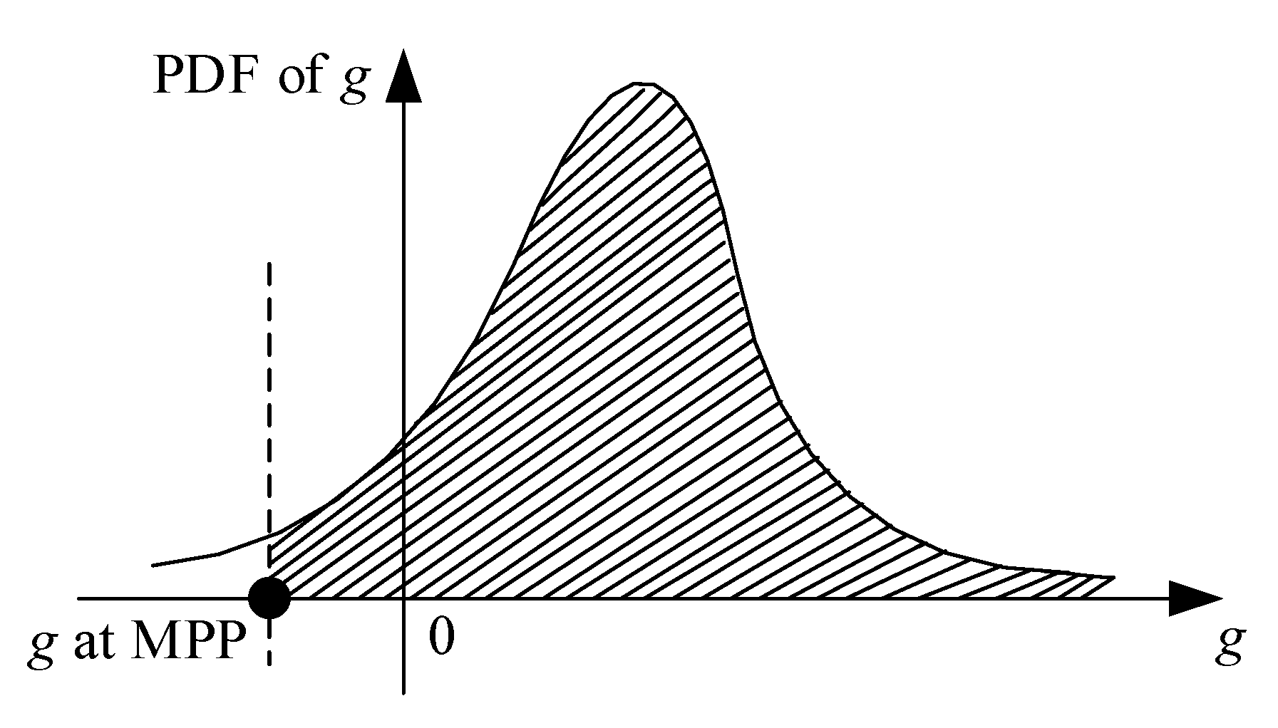
where represents the input of coupled information from discipline to discipline . The reliability constraint is not satisfied, while the function value at MPP is less than zero, as shown in Figure 1.

Figure 1.
Probability density function of g [37].
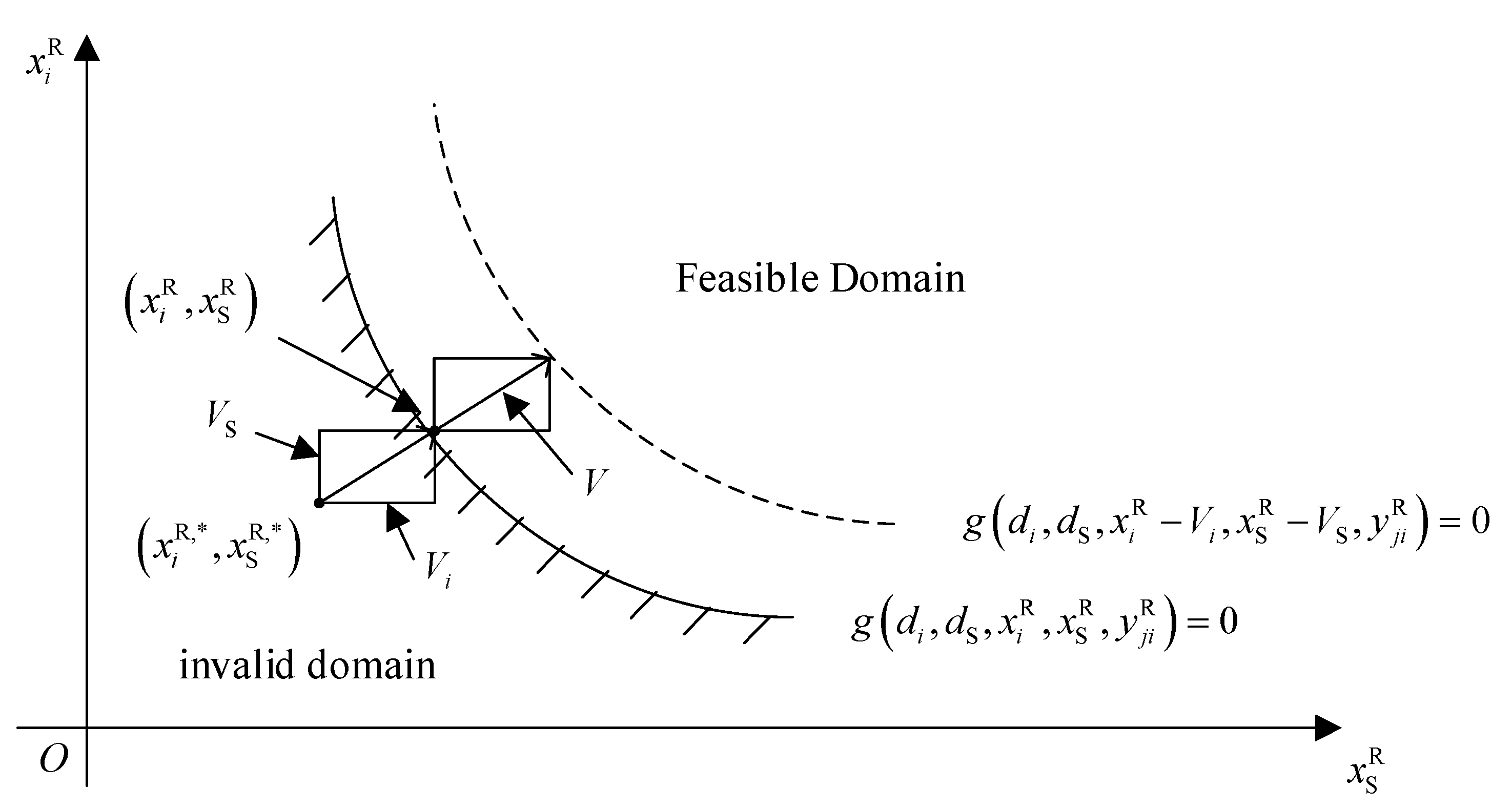
Uncertainty constraints contain the discipline design variable and shared variable , . The deterministic design options and are usually within the boundaries of the feasible region. In this case, the reliability of is about 0.5. The MPP is in zone . The uncertainty constraint can be satisfied by . The deterministic constraints can be moved to the feasible domain by constructing a shift vector through MPP, as shown in Figure 2.

Figure 2.
Movement constraints constructed by the movement vectors.
In Figure 2, the shift vector is obtained by
In a SORA, uncertainty assessment can be completed using many methods, such as FORM, SORM, and saddle-point approximation (SPA) [38,39,40]. The deterministic design optimization model can be expressed as:
Once Equation (4) is obtained, the decoupling of uncertainty evaluation and deterministic design is achieved. Compared with RIA, PMA has high computational efficiency and good robustness. To improve RBMDO efficiency, PMA can be used. In PMA, the random variable in space becomes the random variable in space. Then, the MPP corresponding to is obtained by Equation (5):
where represents the norm of the vector .
Then, the corresponding performance measure is evaluated by:
Therefore, the deterministic design optimization model in Equation (4) can be expressed as:
The solution efficiency of Equation (7) is higher than that of Equation (4).
2.2. Multidisciplinary Uncertainty Analysis Method Considering Aleatory and Interval Uncertainties
In traditional RBMDO, design variables with uncertainty are generally regarded as random variables. However, some uncertain variables cannot be described by probability distributions [41,42,43]. Interval theory can be used to describe only those whose values are known to be in a certain interval. An RBMDO considering interval variables has greater computational pressure. To solve this problem, a multidisciplinary reliability analysis method based on the worst reliability of interval variables is proposed in this study.
Interval variables exist when interval uncertainty exists in multidisciplinary engineering. The superscript “I” is used to denote interval variables in this study. The interval variable is characterized by a specific interval . The RBMDO optimization model of mixed random and interval variables can be expressed as:
where represents the midpoint of the interval variable value.
The subject consistency analysis in the inner loop can be expressed as:
where .
Reliability is defined in this study as the worst-case probability. The optimization model in the outer loop is to find the worst reliability caused by interval uncertainty [43,44,45,46], as shown in Equation (10):
The optimization model of the middle ring and the inner ring is to find the MPP while maintaining the multi-disciplinary balance, as shown in Equation (11):
where represents the desired reliability.
The solutions of the models in Equations (10) and (11) are the worst-case MPP corresponding to . The worst-case performance metric can be calculated as:
where and .
Considering the system optimization, the RBMDO is a four-loop process. The three-loop process of uncertainty analysis can be transformed into a two-loop process by combining Equations (10) and (11), which is given as:
2.3. Multidisciplinary Optimization Solution Considering Aleatory and Interval Uncertainties
The decoupling of the reliability analysis loop and the deterministic optimization loop through the SORA is the basic idea of this section [47]. The CO algorithm is used in a deterministic multidisciplinary optimization loop. The multidisciplinary uncertainty analysis method proposed in Section 2.2 is used in the reliability analysis loop.
2.3.1. SORA Strategy
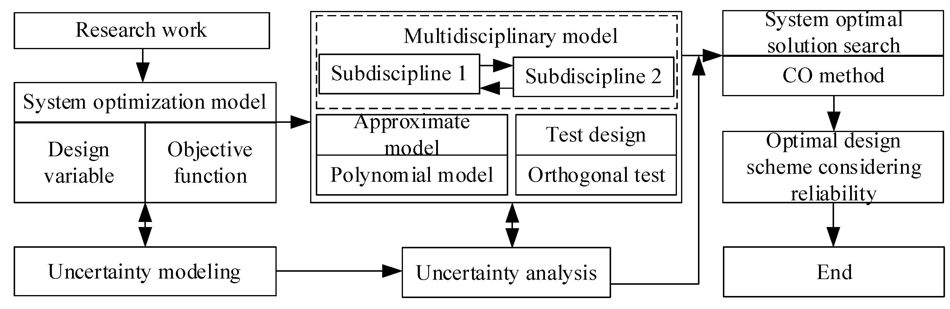
Deterministic optimization and reliability analysis are independent of each other through the SORA strategy [48]. Based on the way that the equivalence constraints are shifted to the probability constraints, the RBMDO problem can be approximately transformed into an MDO problem by the SORA in Figure 3. Finally, the solution is completed using the theory of the MDO [49].
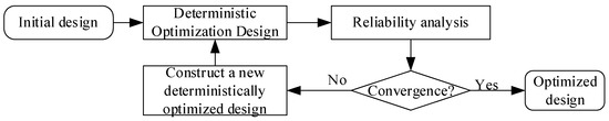
Figure 3.
Flow chart of the SORA method.
2.3.2. CO Algorithm
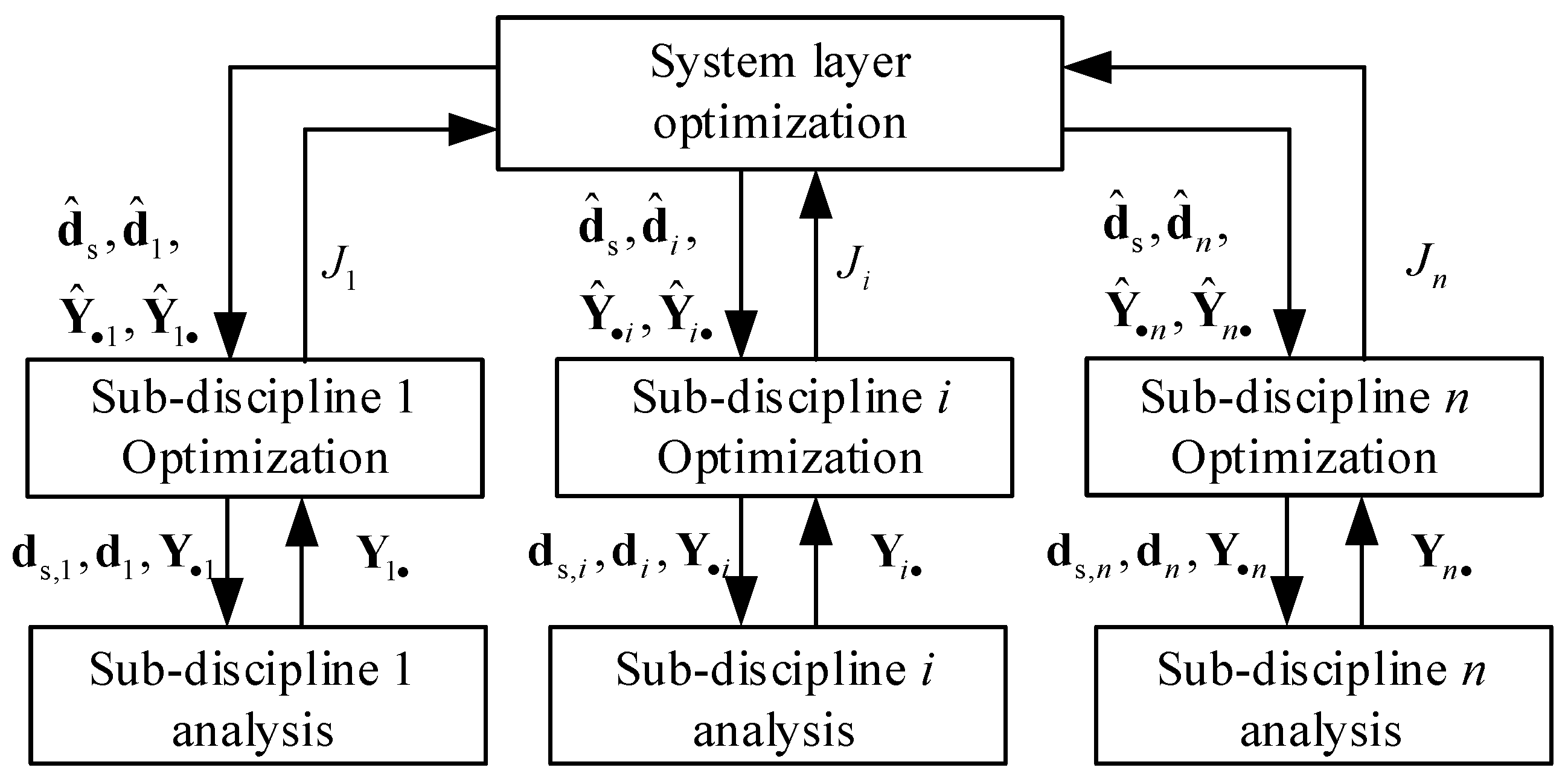
The CO method belongs to the MDO multistage method [50,51]. MDO problems can be divided into system-level problems and sub-discipline-level problems by the CO method [52,53]. The system-level optimization model can be expressed as:
where is the auxiliary design variable; is the compatibility constraint of the i-th subject; and is the shared variable of the i-th subject. The optimization model of the i-th discipline in the sub-discipline layer can be expressed as:
System analysis is not performed in the CO method, while sub-discipline analysis is performed independently in parallel, as shown in Figure 4. The difference between the discipline design variables and the system-level design variables is minimized by the sub-discipline optimization problem. Design solutions that meet the consistency requirements are output by the system layer through compatibility constraints.
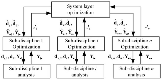
Figure 4.
CO method strategy.
The CO method has a simple structure. The application is simple with its distributed design optimization system. The system can be designed as a whole by the discipline designer using the sub-discipline optimizer. The direct transfer of coupled information between sub-disciplines can be avoided by compatibility constraints.
2.3.3. Optimization Solution
Considering the worst case of interval combinations, the RBMDO in Equation (8) can be remodeled as:
The efficiency of the RBMDO can be improved by PMA. The PMA-based RBMDO model can be expressed as:
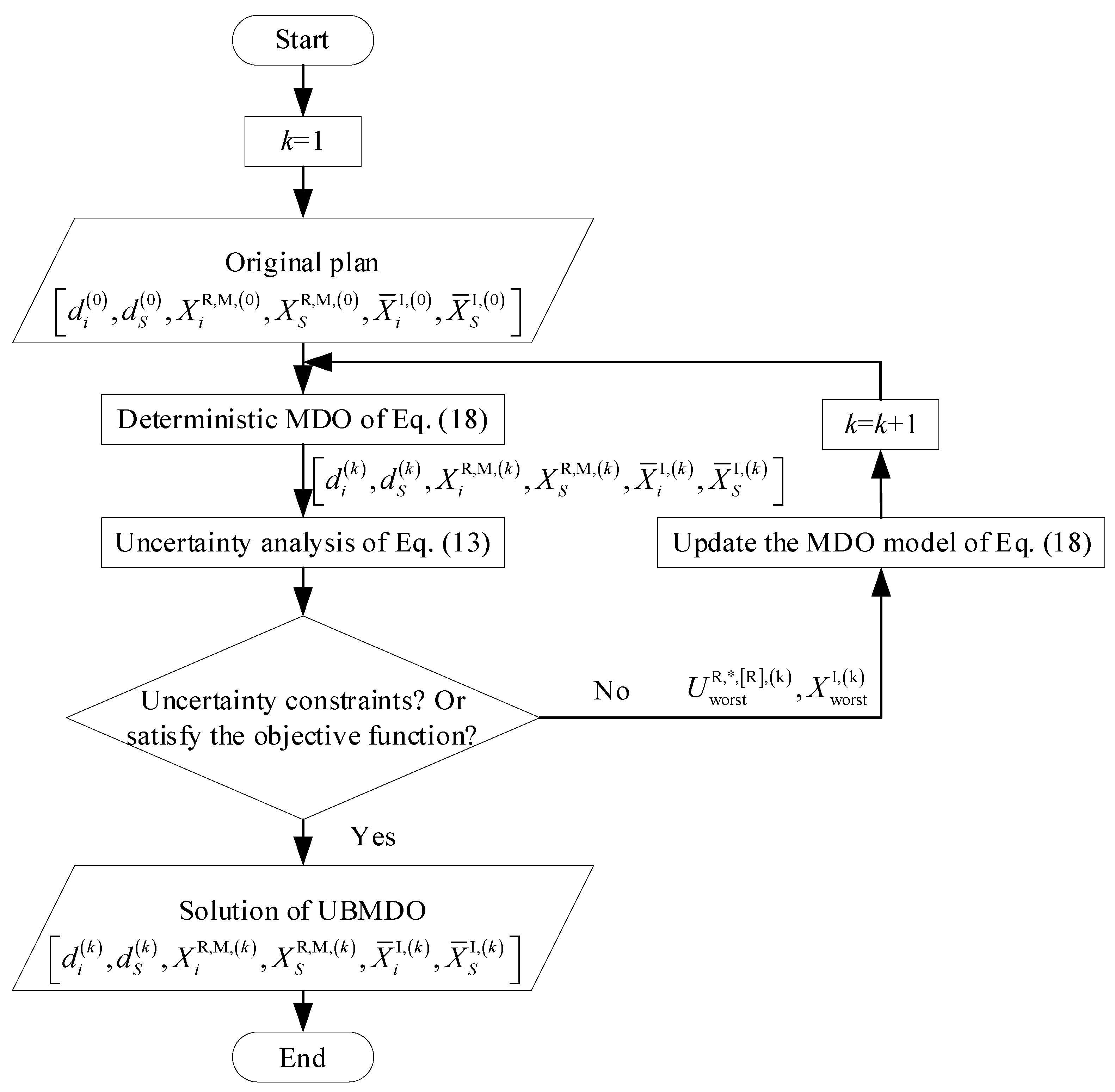
The deterministic design optimization problem in the first cycle of the SORA is shown in Equation (18):
and are set as the interval variable and random variable mean in sequence 1. The optimal design can be obtained after the deterministic optimization and reliability analysis of sequence 1. Since the uncertainty is not considered in the first cycle, the reliability of the design scheme is low. The interval variable and the MPP point of sequence 1 can be obtained by using Equation (19) based on PMA. When , the optimization model of the next sequence is constructed by selecting and as the initial points.
Then, the deterministic optimization model in sequence 2 can be expressed as:
The process of sequence 1 is repeated by sequence 2. If the convergence conditions are satisfied, the result is output, otherwise it continues. The entire operation flow chart is shown in Figure 5.
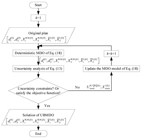
Figure 5.
MDO solution flow chart for mixed aleatory and interval uncertainties.
3. Response Surface Modeling of Rotor Mechanism Based on Virtual Prototype
3.1. Discipline Division and Design Optimization of the Rotor Mechanism
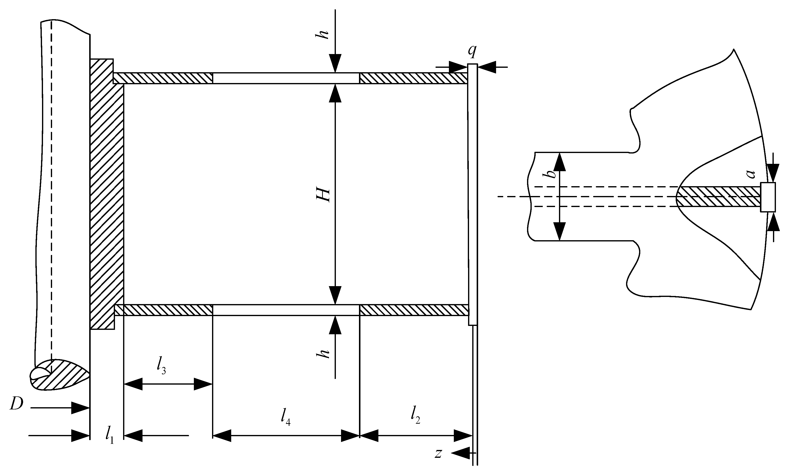
The core component in a hydro-generator set is the rotor. The force of the rotor mechanism of the hydro turbine is complex [54,55]. Strength and stiffness need to be satisfied in the process of creating a lightweight structure. Rotor weight and rotor component stress are two important performance indicators in the MDO problem of turbine rotors. The rotor mechanism weight is selected as the objective function. The remaining performance indicators are selected as the constraint function. There are four local variables, three coupling variables, four shared variables, and two parameters: yoke section weakening coefficient and correction coefficient , which are selected in determining the design optimization problem. The variable information is shown in Table 1 and Figure 6. is the gravity of the rib, is the centrifugal force received by the rib, and the number of the rib is eight.

Table 1.
Variable information in the rotor mechanism design optimization problem.
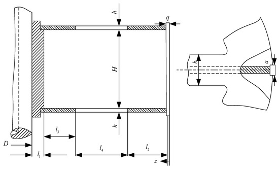
Figure 6.
Schematic diagram of the actual meaning of the design variables.
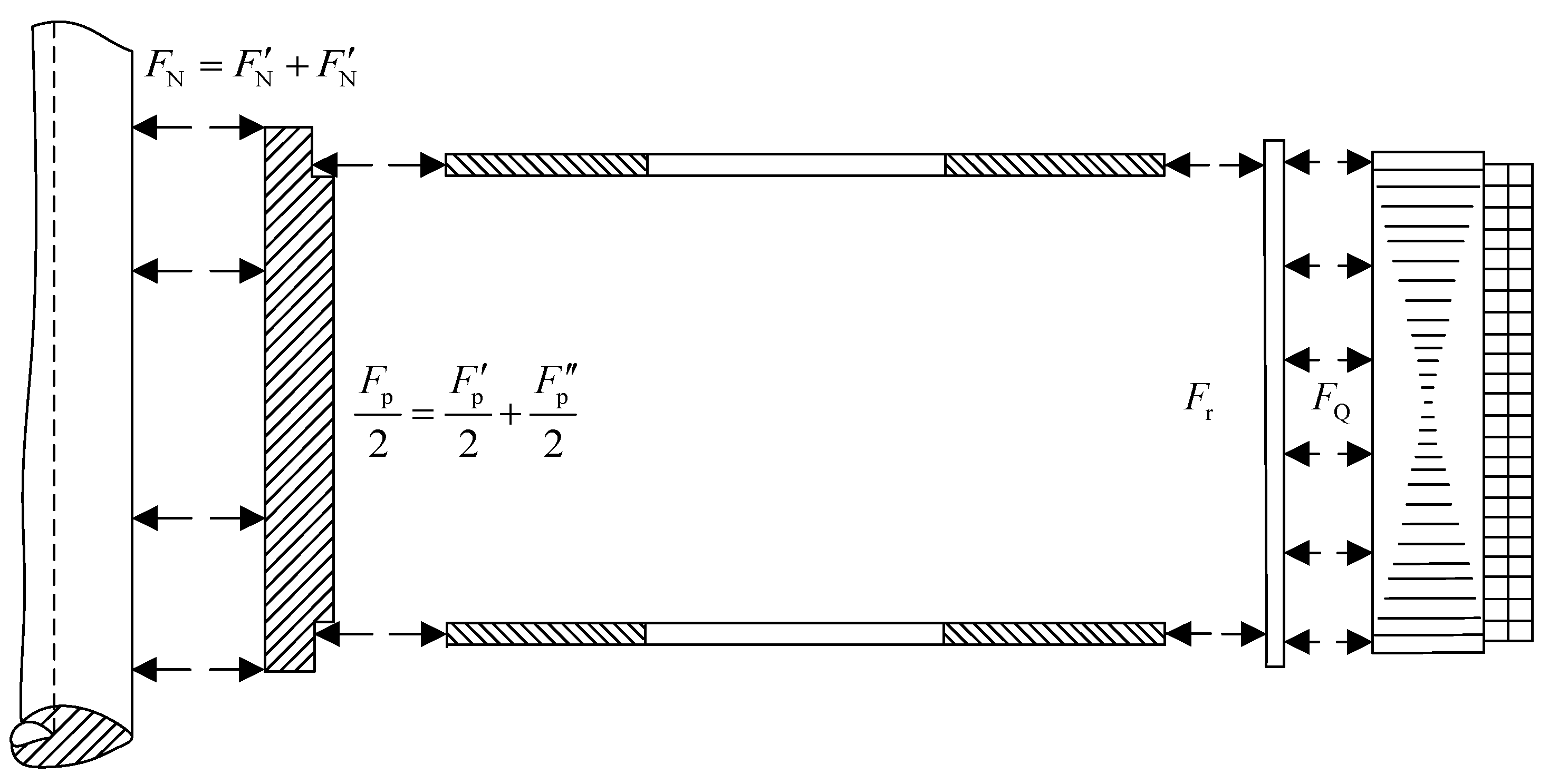
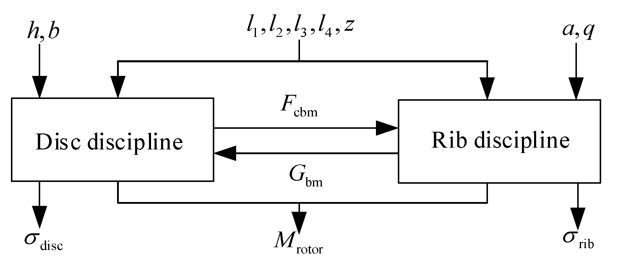
Different parts of the product can be used as the basis for the division of disciplines in the MDO [56,57]. Therefore, the rotor mechanism of the turbine can be divided into the disciplines of disc and rib. The stress situation of the two disciplines containing components is shown in Figure 7. The cooperating force between the wheel hub and the disc and the cooperating force between the disc and the rib are included in the disc discipline. The cooperating force between the rib and the disk and the yoke action are included in the rib discipline. The subject relationship is shown in Figure 8. Improving the ability of the disc to resist deformation and its stiffness is the function of the rib. The acting on the disc is limited by the input by the rib discipline to the disc discipline. Meanwhile, the tearing of the rib to the disc is caused by the action of . Therefore, the of the rib is restricted by the input from the disc subject to the rib subject in order to prevent failure.
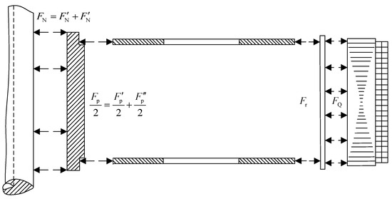
Figure 7.
Force diagram of components.
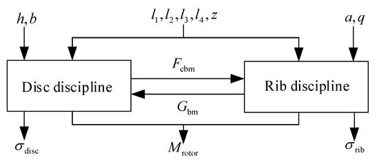
Figure 8.
Disciplinary coupling relationship of the rotor mechanism.
is used as the objective function of the rotor mechanism design optimization problem. The strength of each part of the mechanism and the reasonable range of variation in size are used as constraints.
The deterministic design optimization model of the rotor mechanism can be expressed as:
where and are coupling variables, and
where , , and are calculated from , , , and . The variables are shown in Equations (23)–(30).
where , , are the calculation coefficients of the design variables. The rotor is welded by a wheel hub, an upper disc, a lower disc, a support plate, and a vertical rib. The steel casting is used by the wheel hub, while the material is 20SiMn. Therefore, the allowable strength is 500 MPa in the wheel hub strength constraint. Q235-A is adopted by the rest of the components. Therefore, the allowable strength is 235 MPa in the strength constraints of the disc and rib.
3.2. Response Surface Modeling of Rotor Mechanism Based on Virtual Prototype
The application of virtual prototyping technology is growing rapidly. Its design application runs through the whole life design cycle of the product [58,59].
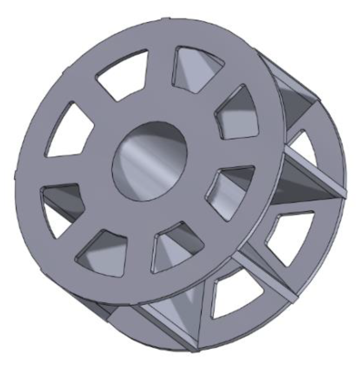
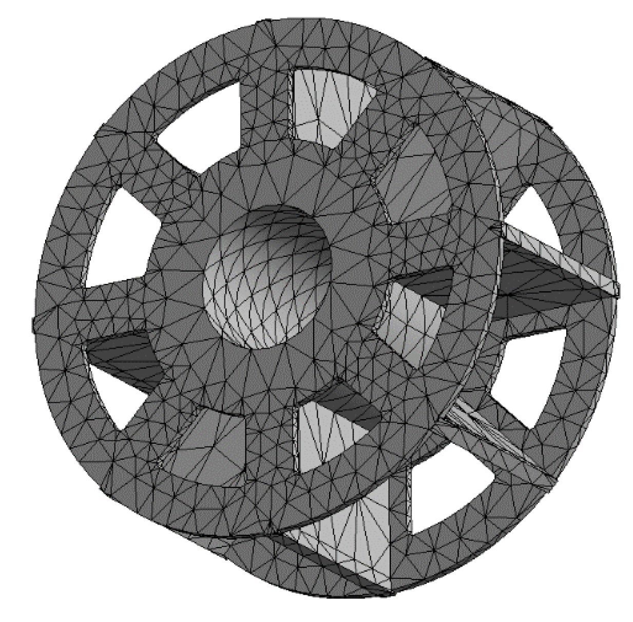
In this article, ISIGHT 9.0 software, which is published by SIGHTNA TECHNOLOGIES, is used to simulate and analyze the structural mechanical characteristics of the rotor structure. As a third-party software, ISIGHT 9.0 can perform modeling, simulation, and optimization. Then, the model shown in Figure 9 is imported into the finite element analysis environment. Next, the physical properties of the model material such as Poisson’s ratio, allowable strength, elastic modulus, etc. are set and adjusted. The method of free meshing is adopted to divide the model in this chapter, as shown in Figure 10.
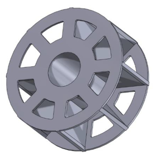
Figure 9.
3D model of the rotor mechanism.
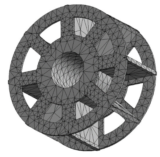
Figure 10.
Mesh division of the rotor mechanism.
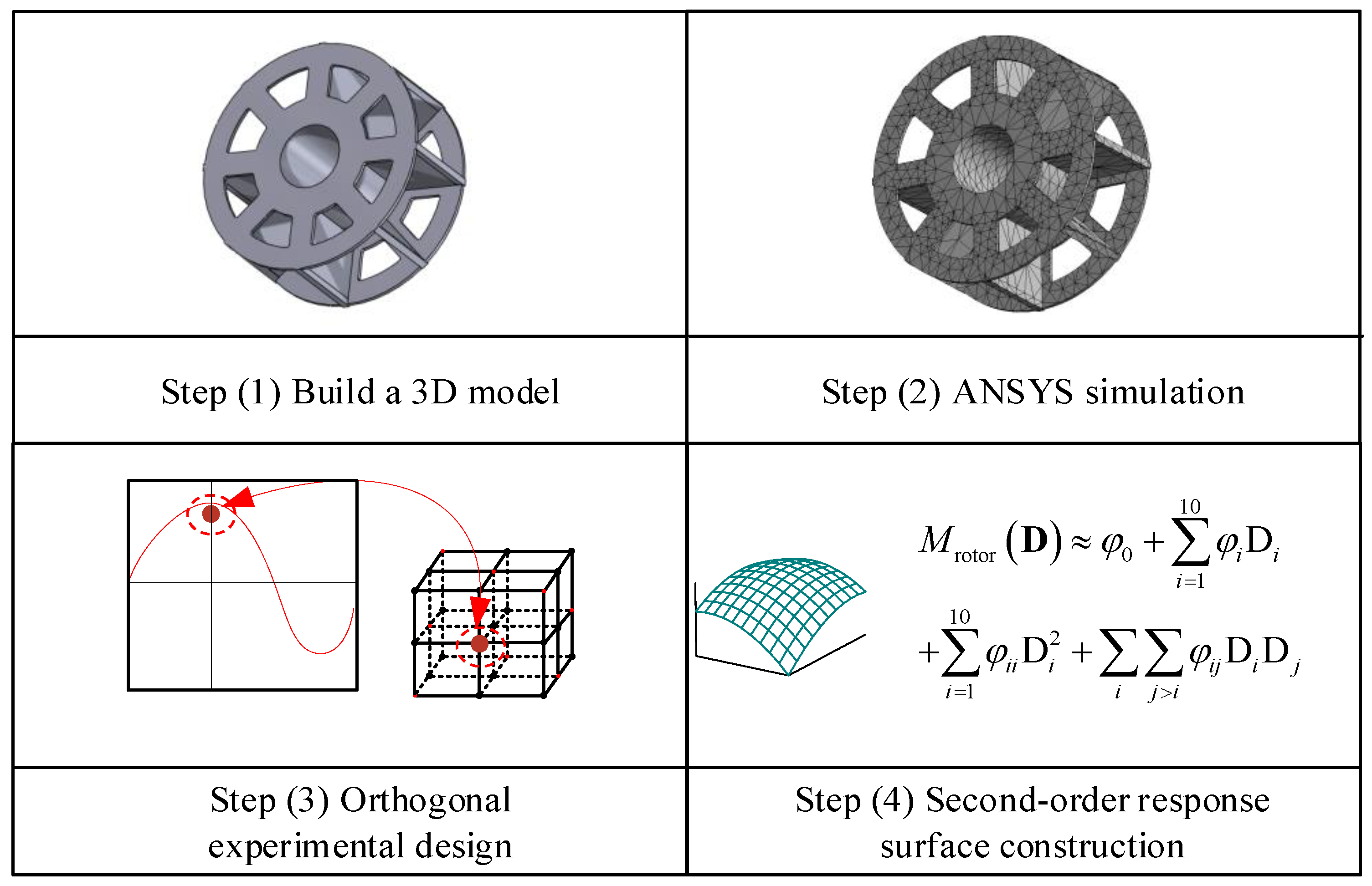
The approximation techniques are one of the key research techniques for modern MDO problems. Approximate models can be used to improve the efficiency of solving complex model problems [60]. A second-order polynomial response surface is a widely used approximation technique. Modeling was carried out using a design of experiments approach.
The second-order polynomial response surface method is adopted in this study. The coefficient in Equation (25) can be obtained by the least-squares regression method and the orthogonal test [61].
where is the test factor required to establish the orthogonal test of the rotor mass response surface. The complete process of building a response surface is shown in Figure 11.
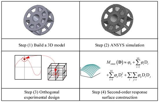
Figure 11.
Orthogonal test process and response surface construction of the rotor.
4. Uncertainty Optimal Analysis of Rotor Mechanism
4.1. Uncertainty Analysis
Various uncertain factors exist in the design optimization problem of the rotor mechanism. Objective uncertainties including part manufacturing dimensions, component assembly, and cognitive uncertainties including design uncertainties are mainly considered in this study. Design variables and parameters with cognitive and aleatory uncertainties are characterized in this study by interval and random variables. The MDO method with mixed random and interval variables is used for the optimal design of the rotor mechanism. The final output is the design scheme under the interval and aleatory uncertainty of the rotor mechanism. The uncertainty information of design variables and design parameters are shown in Table 2 and Table 3.
Table 2.
Uncertainty description of each aleatory variable in the rotor mechanism design optimization problem.
Table 3.
Uncertainty description of each interval variable in the rotor mechanism design optimization problem.
The reliability design optimization model of the rotor mechanism considering the uncertainty information of each random and interval variable is:
4.2. Optimization Considering Uncertainty
The reliability is set to 0.99 in this study. The MDO under aleatory and interval uncertainties is used for design optimization in this section. The rotor mechanism RBMDO process is shown in Figure 12.

Figure 12.
Flow chart of the rotor mechanism optimization considering mixed uncertainties.
The rotor mass is the only system objective function possessed by the rotor optimization problem. Therefore, the CO method can be used to perform the deterministic MDO under the SORA strategy. The system-level optimization model of the rotor optimization problem can be expressed as:
where , , and are the corresponding mean values of the disc discipline coupling variables; and , and are the corresponding mean values of the coupling variables of the discipline of reinforcement.
The disc discipline optimization model can be expressed as:
The optimization model of the rib discipline can be expressed as:
The exchange between the discipline layer and the system layer in the CO strategy is shown in Figure 13. The optimization results are shown in Table 4.
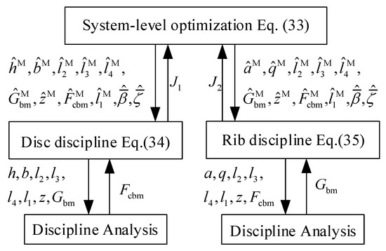
Figure 13.
CO optimization strategy of the rotor mechanism.
Table 4.
Optimization values of the rotor mechanism design variables.
5. Analysis of Rotor Design Optimization Results
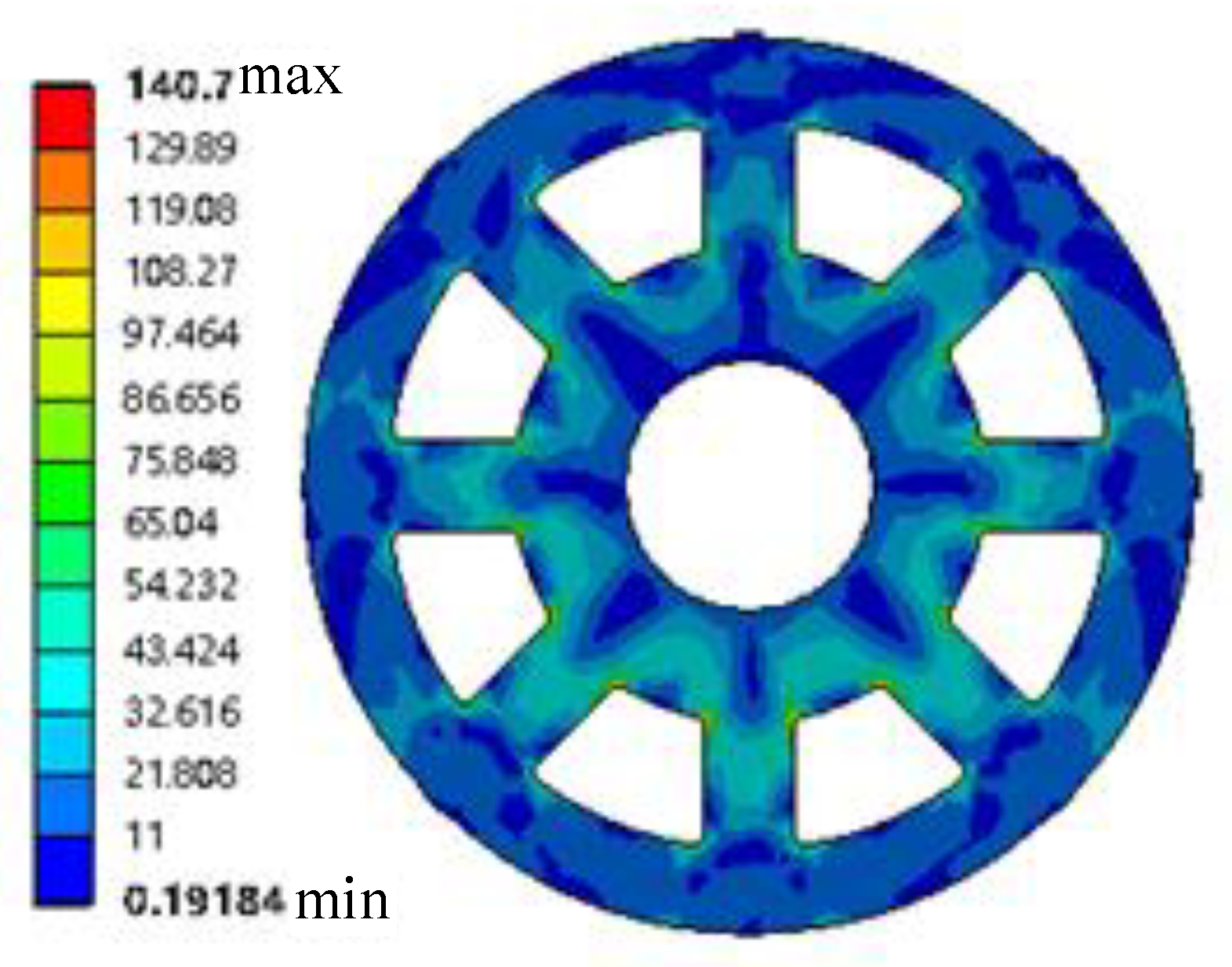
The rotor mass corresponding to the optimized scheme in Table 4 is 7640 kg. Compared with the original data quality, the quality is reduced by 2.6%. The model constraints are satisfied under this design. The rotor mass is alleviated by the optimal design method in this study. Hydroelectric power has been promoted and popularized. The optimized rotor under rated conditions was subjected to static analysis. The fixed displacement constraint is the rotor displacement constraint under rated conditions. The end face connecting the central body and the main shaft is the loading position. The rotor is subjected to electromagnetic resistance torque and gravity during rotation. Overcoming the electromagnetic resistance torque mechanical energy is converted into electrical energy. The fixed distance clearance is possessed by the stator and rotor under ideal conditions. One side of the rotor is far from the stator and the other side is closer due to the existence of machining errors. The extreme value idea is used in this study. Gravity and unilateral magnetic pull are superimposed and loaded to simulate the worst stress situation of the system. Meanwhile, the speed and torque of the rotor mechanism under rated conditions are given. The stress and strain distribution cloud diagrams of the rotor under rated conditions are shown in Figure 14 and Figure 15.

Figure 14.
Stress distribution diagram of the rotor under the rated condition.
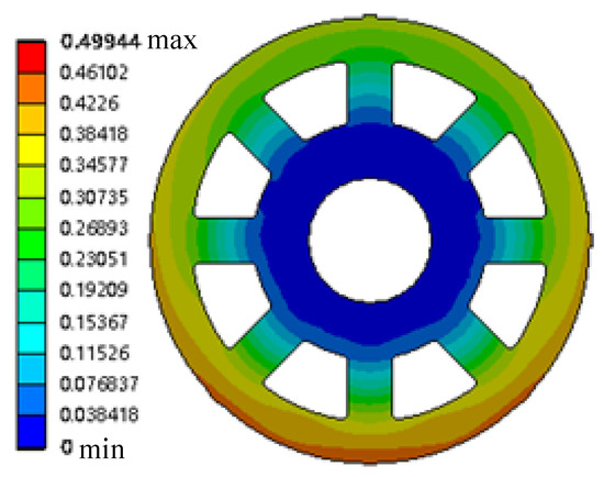
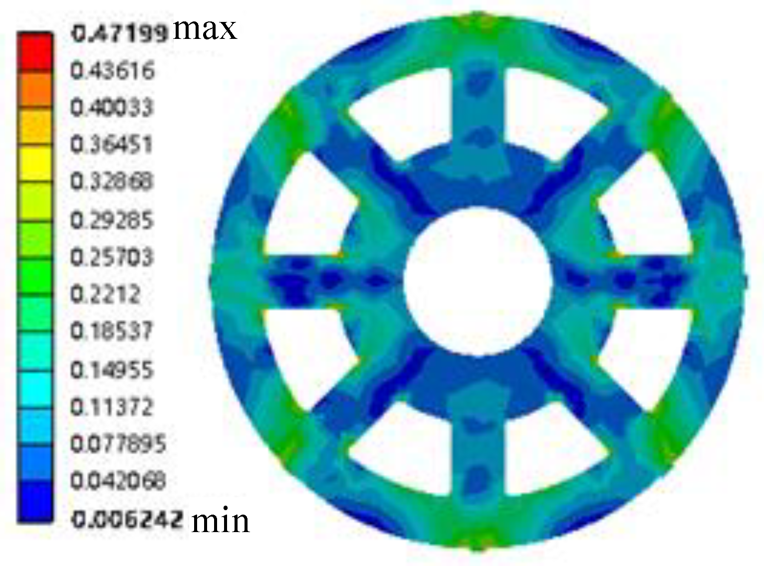
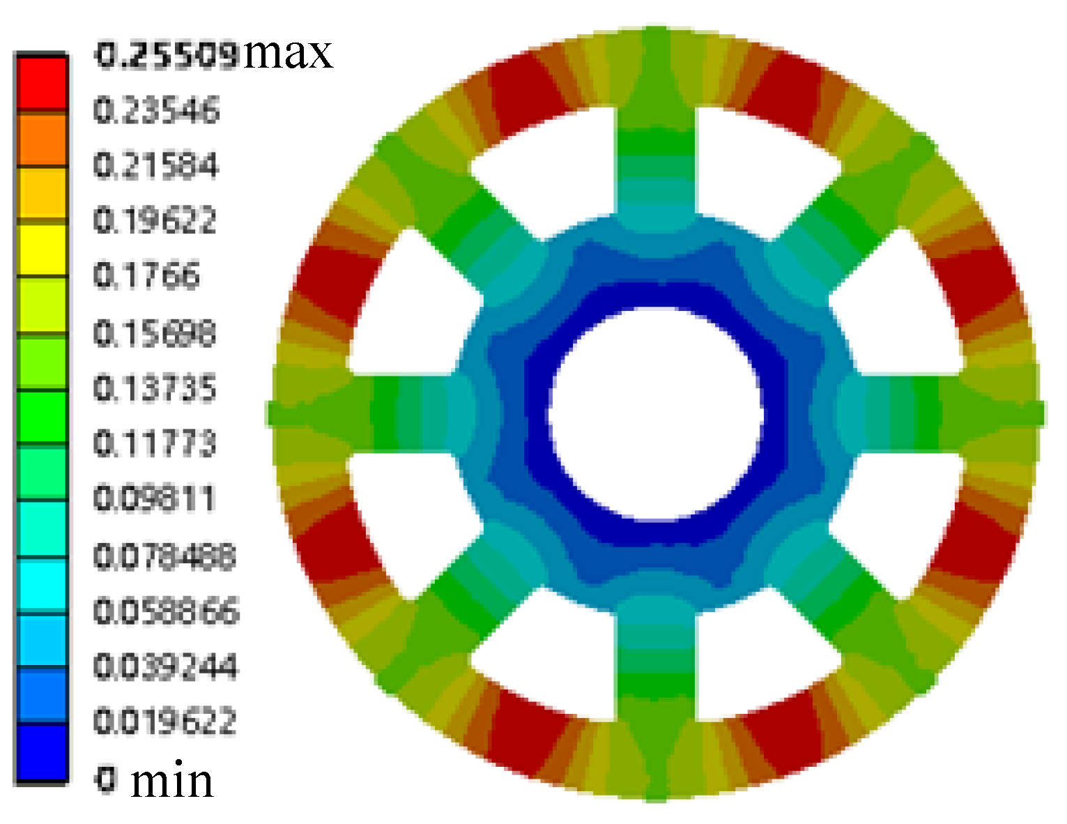
Figure 15.
Strain distribution diagram of the rotor under the rated condition.
The maximum stress value of the rotor under the rated conditions is 140.7 MPa, as shown in Figure 14. The strength constraints in the optimization model are satisfied. The maximum strain value under the rotor rated condition is 0.499, as shown in Figure 15. The deformation constraints in the optimization mathematical model are satisfied. The stress and strain on the model gradually increase due to the continuous optimization of the size. The stiffness and strength constraint extrema are approximated by the simulation results. The optimization results considering aleatory and interval uncertainties are shown to be the optimal design.
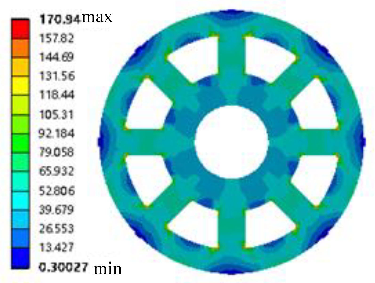
The shutdown and runaway conditions of the rotor are additionally simulated to fully verify the design. The rotor is subjected to magnetic poles and gravity in shutdown conditions. The contours of stress and strain distribution under the rotor shutdown conditions are shown in Figure 16 and Figure 17.
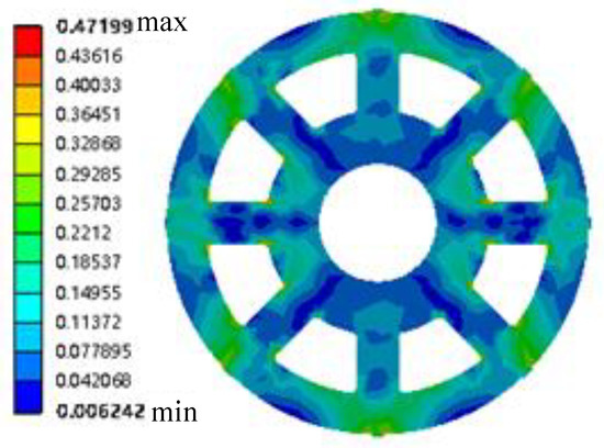
Figure 16.
Stress distribution diagram of the rotor shutdown condition.
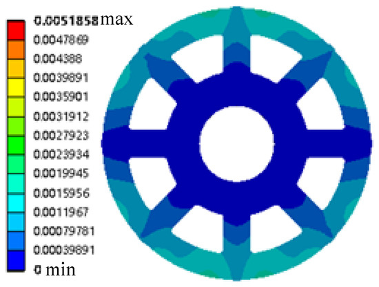
Figure 17.
Strain distribution diagram of the rotor shutdown condition.
The load was suddenly lost and the water guide could not be closed during operation. Meanwhile, the motor output power was zero and the turbine speed increased rapidly. The mechanical energy and water flow energy were equal with increasing rotational speed, while the rotation speed reached an extreme value and was stable. This stable extreme speed is called the runaway speed. The operating condition at this time is called runaway. Runaway must be considered in the design of small- and medium-sized generators. The turbine cannot fail under this condition. There is maximum water flow in runaway conditions, while the speed control protection system fails. The loss of the load causes the unilateral magnetic pull to disappear. At this point, only the gravity of the mechanism exists. The rotor displacement constraint in this condition is consistent with the previous condition. The stress and strain distribution cloud diagrams are shown in Figure 18 and Figure 19.

Figure 18.
Stress distribution diagram of the rotor runaway condition.
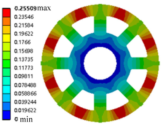
Figure 19.
Strain distribution diagram of the rotor runaway condition.
Therefore, the operating requirements of all operating conditions are met by this design scheme.
6. Conclusions
Based on the multi-source uncertainty, the RBMDO model of the turbine rotor is established in this study. This RBMDO problem is solved by the MDO method under the aleatory and interval uncertainties proposed in this study. The response values of the performance with respect to the experimental factor values are obtained through virtual prototypes and computer simulation software. The response surface of the desired performance function is based on the orthogonal test method and constructed from the obtained response values. The goal of a lightweight structure is achieved under the satisfaction of strength performance.
Author Contributions
Conceptualization, R.Y. and D.M.; methodology, H.L.; software, T.X. and Z.L.; validation, R.Y. and D.M.; formal analysis, H.L. and W.Y.; investigation, H.L.; resources, H.L.; data curation, T.X. and Z.L.; writing—original draft preparation, R.Y.; writing—review and editing, D.M. All authors have read and agreed to the published version of the manuscript.
Funding
This research was funded by the National Natural Science Foundation of China (Grant No. 52175130 and No.52075081), the Sichuan Science and Technology Program (Grant No. 2022YFQ0087), the China Postdoctoral Science Foundation (Grant No. 2021M700693), the Guangdong Basic and Applied Basic Research Foundation (Grant No. 2021A1515012070), the Sichuan Science and Technology Innovation Seedling Project Funding Project (Grant No. 2021112), and the Innovation Training Program for Chengdu University students (CDUCX2022047).
Institutional Review Board Statement
Not applicable.
Informed Consent Statement
Informed consent was obtained from all subjects involved in the study.
Data Availability Statement
The source codes and datasets used to support the findings of this study are available from the corresponding author upon request via email: dbmeng@uestc.edu.cn.
Conflicts of Interest
The authors declare no conflict of interest. The funders had no role in the design of the study; in the collection, analyses, or interpretation of data; in the writing of the manuscript; or in the decision to publish the results.
Nomenclature
| objective function | |
| vector of deterministic design variables | |
| vector of uncertain design variables | |
| vector of coupled variables | |
| constraint function | |
| uncertainty constraint | |
| reliability | |
| reliability index | |
| DV | vector of design variables |
| midpoint of the interval variable value | |
| auxiliary design variable | |
| compatibility constraint of the i-th subject | |
| shared variable of the i-th subject | |
| rotor weight | |
| stress | |
| correction coefficient | |
| gravity of the rib | |
| centrifugal force received by the rib | |
| cooperating force between the wheel hub and the disc | |
| cooperating force between the disc and the rib | |
| yoke action |
References
- Agarwal, H.; Renaud, J.E.; Preston, E.L.; Padmanabhan, D. Uncertainty quantification using evidence theory in multidisciplinary design optimization. Reliab. Eng. Syst. Saf. 2004, 85, 281–294. [Google Scholar] [CrossRef]
- Oberkampf, W.L.; Helton, J.C.; Joslyn, C.A.; Wojtkiewicz, S.F.; Ferson, S. Challenge problems: Uncertainty in system response given uncertain parameters. Reliab. Eng. Syst. Saf. 2004, 85, 11–19. [Google Scholar] [CrossRef]
- Klir, G.J. Generalized information theory: Aims, results, and open problems. Reliab. Eng. Syst. Saf. 2004, 85, 21–38. [Google Scholar] [CrossRef]
- Meng, D.; Lv, Z.; Yang, S.; Wang, H.; Xie, T.; Wang, Z. A time-varying mechanical structure reliability analysis method based on performance degradation. Structures 2021, 34, 3247–3256. [Google Scholar] [CrossRef]
- Meng, D.; Yang, S.; Lin, T.; Wang, J.; Yang, H.; Lv, Z. RBMDO using gaussian mixture model-based second-order mean-value saddlepoint approximation. CMES-Comp. Model. Eng. 2022, in press. [Google Scholar]
- Ai, Q.; Yuan, Y.; Mahadevan, S.; Jiang, X. Probabilistic degradation modelling of circular tunnels assembled from segmental linings. Struct. Concrete. 2016, 17, 257–273. [Google Scholar] [CrossRef]
- Su, X.; Li, L.; Qian, H.; Mahadevan, S.; Deng, Y. A new rule to combine dependent bodies of evidence. Soft Comput. 2019, 23, 9793–9799. [Google Scholar] [CrossRef]
- Su, X.; Li, L.; Shi, F.; Qian, H. Research on the fusion of dependent evidence based on mutual information. IEEE Access 2018, 6, 71839–71845. [Google Scholar] [CrossRef]
- Zhu, S.P.; Huang, H.Z.; Peng, W.; Wang, H.K.; Mahadevan, S. Probabilistic physics of failure-based framework for fatigue life prediction of aircraft gas turbine discs under uncertainty. Reliab. Eng. Syst. Saf. 2016, 146, 1–12. [Google Scholar] [CrossRef]
- Meng, D.; Hu, Z.; Guo, J.; Lv, Z.; Xie, T.; Wang, Z. An uncertainty-based structural design and optimization method with interval Taylor expansion. Structures 2021, 33, 4492–4500. [Google Scholar] [CrossRef]
- Jiang, C.; Zheng, J.; Han, X. Probability-interval hybrid uncertainty analysis for structures with both aleatory and epistemic uncertainties: A review. Struct. Multidiscip. Optim. 2018, 57, 2485–2502. [Google Scholar] [CrossRef]
- Hüllermeier, E.; Waegeman, W. Aleatoric and epistemic uncertainty in machine learning: An introduction to concepts and methods. Mach. Learn. 2021, 110, 457–506. [Google Scholar] [CrossRef]
- Zhi, P.; Li, Y.; Chen, B.; Li, M.; Liu, G. Fuzzy optimization design-based multi-level response surface of bogie frame. Int. J. Struct. Integr. 2019, 10, 134–148. [Google Scholar] [CrossRef]
- Li, H.S.; Dong, Q.Y.; Yuan, J.Y. Augmented Lagrangian teaching–learning-based optimization for structural design. Proc. Inst. Mech. Eng. Part G J. Aerosp. Eng. 2018, 232, 2195–2213. [Google Scholar] [CrossRef]
- Meng, D.; Wang, H.; Yang, S.; Lv, Z.; Hu, Z.; Wang, Z. Fault analysis of wind power rolling bearing based on EMD feature extraction. CMES-Comp. Model. Eng. 2022, 130, 543–558. [Google Scholar] [CrossRef]
- Wang, L.; Xiong, C.; Yang, Y. A novel methodology of reliability-based multidisciplinary design optimization under hybrid interval and fuzzy uncertainties. Comput. Methods Appl. Mech. Eng. 2018, 337, 439–457. [Google Scholar] [CrossRef]
- Benaouali, A.; Kachel, S. Multidisciplinary design optimization of aircraft wing using commercial software integration. Aerosp. Sci. Technol. 2019, 92, 766–776. [Google Scholar] [CrossRef]
- Zhu, D.; Zhou, J.; Liu, C.; Wang, Z. A short review of reliability-based design optimization. In Proceedings of the IOP Conference Series: Materials Science and Engineering, Shaanxi, China, 8–11 October 2020. [Google Scholar]
- Dutta, S.; Putcha, C. Reliability-Based Design Optimization of a Large-Scale Truss Structure using Polynomial Chaos Expansion Metamodel; Reliability, Safety and Hazard Assessment for Risk-based Technologies; Springer: Singapore, 2020; pp. 481–488. [Google Scholar]
- Cho, H.; Choi, K.K.; Shin, J. Iterative most probable point search method for problems with a mixture of random and interval variables. J. Mech. Design 2020, 142, 071703. [Google Scholar] [CrossRef]
- Sun, W.; Guo, Z. Mathematical modeling and nonlinear vibration analysis of a coupled hydro-generator shaft-foundation system. Commun. Nonlinear Sci. 2021, 98, 105776. [Google Scholar] [CrossRef]
- Mao, X.; Pavesi, G.; Zheng, Y. Francis-type reversible turbine field investigation during fast closure of wicket gates. J. Fluids Eng. 2018, 140, 061103. [Google Scholar]
- Salehi, S.; Nilsson, H.; Lillberg, E.; Edh, N. An in-depth numerical analysis of transient flow field in a Francis turbine during shutdown. Renew. Energ. 2021, 179, 2322–2347. [Google Scholar] [CrossRef]
- Goyal, R.; Gandhi, B.K. Review of hydrodynamics instabilities in Francis turbine during off-design and transient operations. Renew. Energ. 2018, 116, 697–709. [Google Scholar] [CrossRef]
- Unterluggauer, J.; Sulzgruber, V.; Doujak, E.; Bauer, C. Experimental and numerical study of a prototype Francis turbine startup. Renew. Energ. 2020, 157, 1212–1221. [Google Scholar] [CrossRef]
- Yao, S.; Griffith, D.T.; Chetan, M.; Bay, C.J.; Damiani, R.; Kaminski, M.; Loth, E. A gravo-aeroelastically scaled wind turbine rotor at field-prototype scale with strict structural requirements. Renew. Energ. 2020, 156, 535–547. [Google Scholar] [CrossRef]
- Ciappi, L.; Fiaschi, D.; Niknam, P.H.; Talluri, L. Computational investigation of the flow inside a Tesla turbine rotor. Energy 2019, 173, 207–217. [Google Scholar] [CrossRef]
- Alom, N.; Saha, U.K. Four decades of research into the augmentation techniques of Savonius wind turbine rotor. J. Energ. Resour. Technol. 2018, 140, 050801. [Google Scholar] [CrossRef]
- Nya, R.M.; Abdullah, S.; Singh, S.S.K. Reliability-based fatigue life of vehicle spring under random loading. Int. J. Struct. Integr. 2019, 10, 737–748. [Google Scholar]
- Kebir, T.; Correia, J.; Benguediab, M.; De Jesus, A.M. Numerical study of fatigue damage under random loading using Rainflow cycle counting. Int. J. Struct. Integr. 2020, 12, 149–162. [Google Scholar] [CrossRef]
- Gao, X.; Su, X.; Qian, H.; Pan, X. Dependence assessment in human reliability analysis under uncertain and dynamic situations. Nucl. Eng. Technol. 2022, 54, 948–958. [Google Scholar] [CrossRef]
- Ai, Q.; Yuan, Y.; Mahadevan, S.; Jiang, X. Maintenance strategies optimisation of metro tunnels in soft soil. Struct. Infrastruct. Eng. 2017, 13, 1093–1103. [Google Scholar] [CrossRef]
- Du, W.; Luo, Y.; Wang, Y. A time-variant performance measure approach for dynamic reliability based design optimization. Appl. Math. Model. 2019, 76, 71–86. [Google Scholar] [CrossRef]
- Keshtegar, B.; Hao, P. Enriched self-adjusted performance measure approach for reliability-based design optimization of complex engineering problems. Appl. Math. Model. 2018, 57, 37–51. [Google Scholar] [CrossRef]
- Keshtegar, B.; Hao, P. A hybrid descent mean value for accurate and efficient performance measure approach of reliability-based design optimization. Comput. Methods Appl. Mech. Eng. 2018, 336, 237–259. [Google Scholar] [CrossRef]
- Chen, L.; Deng, Y. An improved evidential Markov decision making model. Appl. Intell. 2022, 52, 8008–8017. [Google Scholar] [CrossRef]
- Du, X.; Sudjianto, A.; Chen, W. An integrated framework for optimization under uncertainty using inverse reliability strategy. J. Mech. Design 2004, 126, 562–570. [Google Scholar] [CrossRef]
- Wang, L.; Xiong, C.; Hu, J.; Wang, X.; Qiu, Z. Sequential multidisciplinary design optimization and reliability analysis under interval uncertainty. Aerosp. Sci. Technol. 2018, 80, 508–519. [Google Scholar] [CrossRef]
- Wang, L.; Xiong, C.; Wang, X.; Liu, G.; Shi, Q. Sequential optimization and fuzzy reliability analysis for multidisciplinary systems. Struct. Multidiscip. Optim. 2019, 60, 1079–1095. [Google Scholar] [CrossRef]
- Du, X.; Guo, J.; Beeram, H. Sequential optimization and reliability assessment for multidisciplinary systems design. Struct. Multidiscip. Optim. 2008, 35, 117–130. [Google Scholar] [CrossRef]
- Li, H.S.; Wang, X.W.; Nan, H.; Liu, M. Application of a sampling-based method for estimation of cumulative failure probability functions of mechanisms. Mech. Mach. Theory. 2021, 155, 104050. [Google Scholar] [CrossRef]
- Wu, Q.; Deng, Y.; Xiong, N. Exponential negation of a probability distribution. Soft Comput. 2022, 26, 2147–2156. [Google Scholar] [CrossRef]
- Meng, D.; Xie, T.; Wu, P.; He, C.; Hu, Z.; Lv, Z. An uncertainty-based design optimization strategy with random and interval variables for multidisciplinary engineering systems. Structures 2021, 32, 997–1004. [Google Scholar] [CrossRef]
- Narayanan, G. Probabilistic fatigue model for cast alloys of aero engine applications. Int. J. Struct. Integr. 2021, 12, 454–469. [Google Scholar] [CrossRef]
- Li, H.S.; Wang, T.; Yuan, J.Y.; Zhang, H. A sampling-based method for high-dimensional time-variant reliability analysis. Mech. Syst. Signal Process. 2019, 126, 505–520. [Google Scholar] [CrossRef]
- Zhu, S.P.; Liu, Q.; Peng, W.; Zhang, X.C. Computational-experimental approaches for fatigue reliability assessment of turbine bladed disks. Int. J. Mech. Sci. 2018, 142, 502–517. [Google Scholar] [CrossRef]
- Zhu, S.P.; Keshtegar, B.; Seghier, M.E.A.B.; Zio, E.; Taylan, O. Hybrid and enhanced PSO: Novel first order reliability method-based hybrid intelligent approaches. Comput. Methods Appl. Mech. Eng. 2022, 393, 114730. [Google Scholar] [CrossRef]
- Abd Rahim, A.A.; Abdullah, S.; Singh, S.S.K.; Nuawi, M.Z. Reliability assessment on automobile suspension system using wavelet analysis. Int. J. Struct. Integr. 2019, 10, 602–611. [Google Scholar] [CrossRef]
- Huang, H.Z.; Zhang, X.; Liu, Y.; Meng, D.; Wang, Z. Enhanced sequential optimization and reliability assessment for reliability-based design optimization. J. Mech. Sci. Technol. 2012, 26, 2039–2043. [Google Scholar] [CrossRef]
- Guo, J.; Zhang, P.; Wu, D.; Liu, Z.; Ge, H.; Zhang, S.; Yang, X. A new collaborative optimization method for a distributed energy system combining hybrid energy storage. Sustain. Cities Soc. 2021, 75, 103330. [Google Scholar] [CrossRef]
- Liu, Z.; Guo, J.; Wu, D.; Fan, G.; Zhang, S.; Yang, X.; Ge, H. Two-phase collaborative optimization and operation strategy for a new distributed energy system that combines multi-energy storage for a nearly zero energy community. Energy Convers. Manag. 2021, 230, 113800. [Google Scholar] [CrossRef]
- Meng, D.; Yang, S.; Zhang, Y.; Zhu, S.P. Structural reliability analysis and uncertainties-based collaborative design and optimization of turbine blades using surrogate model. Fatigue Fract. Eng. Mater. Struct. 2019, 42, 1219–1227. [Google Scholar] [CrossRef]
- Meng, D.; Li, Y.; He, C.; Guo, J.; Lv, Z.; Wu, P. Multidisciplinary design for structural integrity using a collaborative optimization method based on adaptive surrogate modelling. Mater. Design 2021, 206, 109789. [Google Scholar] [CrossRef]
- Xiao, F. CED: A distance for complex mass functions. IEEE Trans. Neural Netw. Learn. Syst. 2020, 32, 1525–1535. [Google Scholar] [CrossRef] [PubMed]
- Xiao, F. CEQD: A complex mass function to predict interference effects. IEEE Trans. Cybern. 2021, 1–13. Available online: https://ieeexplore.ieee.org/abstract/document/9314051 (accessed on 14 May 2022). [CrossRef] [PubMed]
- Ai, Q.; Yuan, Y.; Shen, S.L.; Wang, H.; Huang, X. Investigation on inspection scheduling for the maintenance of tunnel with different degradation modes. Tunn. Undergr. Sp. Tech. 2020, 106, 103589. [Google Scholar] [CrossRef]
- Jahan, A.; Ismail, M.Y.; Sapuan, S.M.; Mustapha, F. Material screening and choosing methods-a review. Mater. Design 2010, 31, 696–705. [Google Scholar] [CrossRef]
- Skjong, S.; Rindarøy, M.; Kyllingstad, L.T.; Æsøy, V.; Pedersen, E. Virtual prototyping of maritime systems and operations: Applications of distributed co-simulations. J. Mar. Sci. Technol. 2018, 23, 835–853. [Google Scholar] [CrossRef] [Green Version]
- Park, H.S.; Dang, D.V.; Nguyen, T.T. Development of a flexible roll forming machine for cutting curved parts with virtual prototyping technology. J. Adv. Mech. Des. Syst. 2019, 13, JAMDSM0033. [Google Scholar] [CrossRef] [Green Version]
- Xiao, F. CaFtR: A fuzzy complex event processing method. Int. J. Fuzzy Syst. 2022, 24, 1098–1111. [Google Scholar] [CrossRef]
- Xue, Y.; Deng, Y. Extending set measures to orthopair fuzzy sets. Int. J. Uncertain. Fuzz. 2022, 30, 63–91. [Google Scholar] [CrossRef]


Publisher’s Note: MDPI stays neutral with regard to jurisdictional claims in published maps and institutional affiliations. |
© 2022 by the authors. Licensee MDPI, Basel, Switzerland. This article is an open access article distributed under the terms and conditions of the Creative Commons Attribution (CC BY) license (https://creativecommons.org/licenses/by/4.0/).