Article

Design and Simulation Experiment of Rigid-Flexible Soft Humanoid Finger

1
School of Mechanical Engineering, Hangzhou Dianzi University, Hangzhou 310018, China
2
State Key Laboratory of Fluid Power and Mechatronic Systems, School of Mechanical Engineering, Zhejiang University, Hangzhou 310027, China
*
Author to whom correspondence should be addressed.
Machines 2022, 10(6), 448; https://doi.org/10.3390/machines10060448
Submission received: 7 May 2022 / Revised: 1 June 2022 / Accepted: 4 June 2022 / Published: 6 June 2022
(This article belongs to the Section Machine Design and Theory)

Abstract

:
This paper is based on the “Fast Pneumatic Mesh Driver” (FPN) used to couple a silicone rubber soft body with a rigid skeleton. A rigid-flexible coupling soft-body human-like finger design scheme is proposed to solve the problem of low load on the soft-body gripping hand. The second-order Yeoh model is used to establish the statics model of the soft humanoid finger, and the ABAQUS simulation analysis software is used for correction and comparison to verify the feasibility of the soft humanoid finger bending. The thickness of the driver cavity and the confining strain layer were determined by finite element simulation. The mold casting process is used to complete the preparation of human-like fingers and design a pneumatic control system for experiments combined with 3D printing technology. The experimental results show that the proposed rigid-flexible coupling soft body imitating the human finger structure can realize the corresponding actions, such as the multi-joint bending and side swinging, of human fingers. Compared with the traditional pure soft-body finger, the fingertip output force is significantly improved. The optimal design and simulation analysis of the human gripper and the feasibility of the application have practical guiding significance.

1. Introduction

The rapid development of industrial automation has put forward higher requirements for the application of end grippers in the production process, especially the safe clamping of irregular items, fragile items and small items [1]. In recent years, flexible mechanical grippers, which are mainly made of flexible materials and driven by soft media, have attracted the extensive attention of researchers. They can adapt to objects of different shapes and interact safely with the environment [2]. Pneumatic drives have the advantages of a large output force, simple control and low requirements for the external environment, and they have been widely used in the drive of soft robots [3]. Soft bionic hands made of flexible materials are increasingly used in medical rehabilitation [4], industrial machine grippers [5] and other fields due to their good environmental adaptability, high flexibility and safe interaction.
With the rapid development of soft bionic hands, a series of new soft structures have emerged [6]. J. Zhou et al. [7] proposed a novel soft-body gripper structure, which consists of three soft-body curved fingers and a passive adaptive palm. Each soft-body finger includes two elliptical-shaped pneumatic chambers, which can grip small objects. However, the interior is limited by the setting of the adaptive palm. D Hardman et al. [8] developed a biodegradable 3D printing material made of low-cost elastic gelatin material and salt that can sense strain, temperature and humidity and “self-heal”, which they used to create soft robots that can bend and perceive. However, due to the influence of liquid flow, it can only output a small force and cannot be used in harsh environments such as low temperatures and strong magnetic fields. Liu, Shoufeng et al. [9] proposed a dual-module pneumatic actuator with variable chamber height. The actuator has compliance and passive adaptability, which can increase the contact area and ensure gripping reliability. However, the dual-module driver has a more complex structure and high design cost. Jing, X et al. [10] discussed the effect of using silicone materials with different hardness in different areas of the actuator on the overall performance of the soft actuator. According to the idea of the multi-hardness silicone structure, a seven-chamber actuator was fabricated, which was actuated with a uniform material. Compared with the first actuator, the performance of this actuator was improved by 90.72%. This article provides a theoretical basis and reference for our selection of silicone materials. Xu, M et al. [11] proposed a dexterous fiber-reinforced flexible joint actuator inspired by spider leg joints. The fabrication process and modeling method of the fan-shaped joint actuator with a fiber-reinforced structure are discussed. However, the practical application of this structure has limitations, it cannot achieve large deformation, and the output force is small. Chen, F et al. [12] realized the control of the geometry and motion characteristics of the actuator through the design of surface parameters, which has excellent mechanical properties with high energy density. It provides new ideas and new methods for the cavity design of pneumatic soft actuators. Huang, W et al. [13] proposed a variable-structure pneumatic soft robot. It is strong and flexible and can adapt to different sizes by actively scaling. Inspired by octopus tentacles, Katia Bertoldi’s team [14] designed a conical elastic air chamber soft actuator that can grasp objects of different shapes and materials, but it moves slowly. Y Zhao et al. [15] developed a variable stiffness flexible continuum actuator and applied it to a pneumatic flexible robot capable of large-load grasping. However, the structure is bulky and cannot grab small objects. Based on soft fabric pneumatic actuators (SFPAs), Ge, L et al. [16] designed three structures of thumb abduction, finger bending and finger extension, and integrated the SFPAs into a flexible wearable auxiliary glove. This enables the practical application of soft manipulators. In order to improve the grasping performance, Zhang, G et al. [17] established the kinematics, mechanics and grasping models of the soft robotic arm, and introduced a control strategy considering genetic algorithms to detect the optimal position of the soft robotic arm. This article mainly studies the algorithm of the soft manipulator, and does not analyze the design, preparation and experiments of the soft actuator.
Compared with the rigid bionic hand, due to the limitation of the performance of flexible materials, the bearing capacity of pure flexible fingers is lower. Therefore, improving the flexibility of soft human finger movement and the bearing capacity of fingertips has become a problem that needs to be solved in the current research. This paper proposes a design scheme that couples the joint air cavity with the rigid skeleton. We carried out theoretical calculations, simulation analysis and device preparation, and realized the bending action of human-like fingers, which provided a reference for the extension design of the soft gripping hand, and at the same time improved the bearing capacity of the soft fingers.

2. Design and Manufacturing

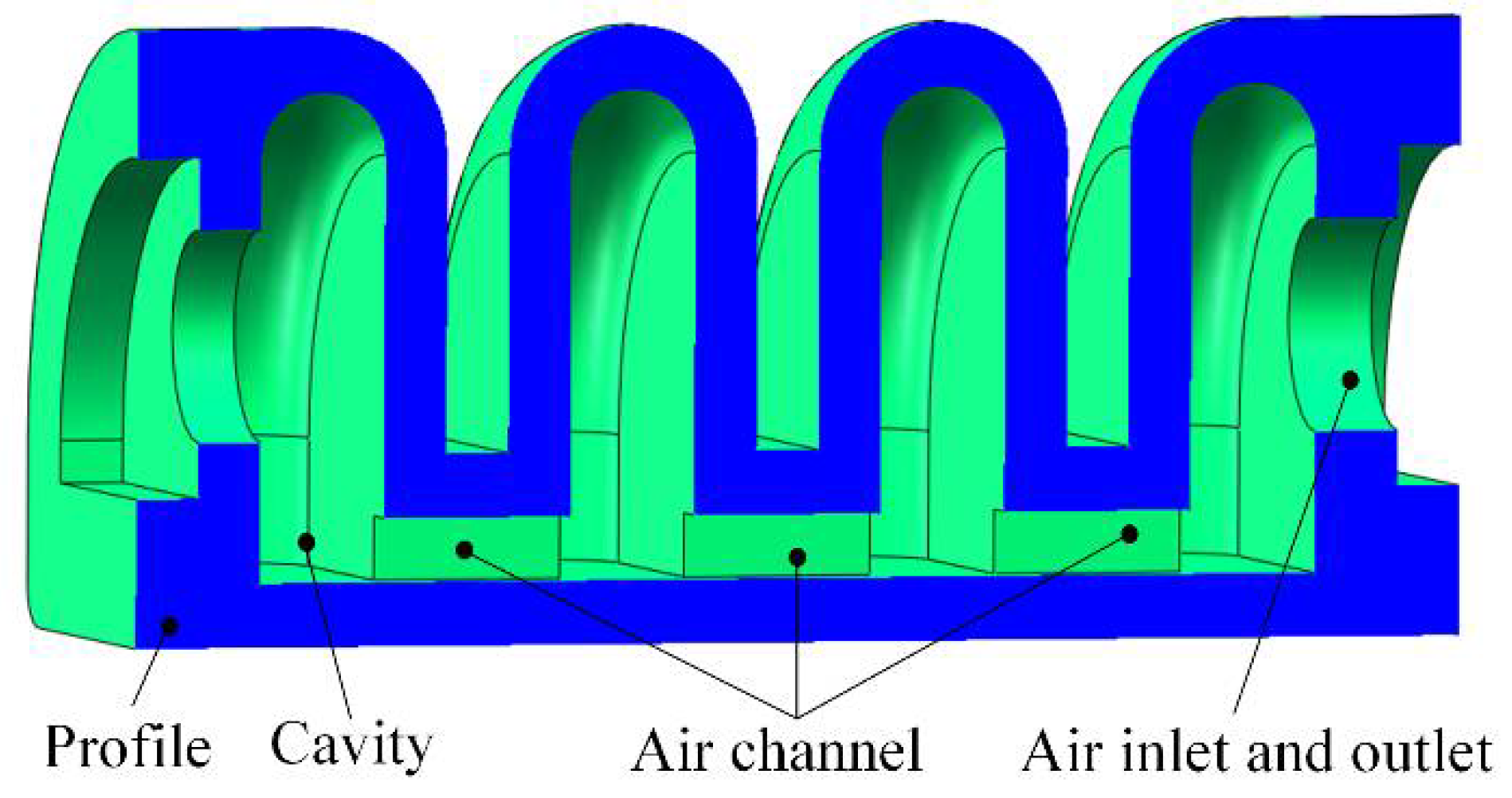
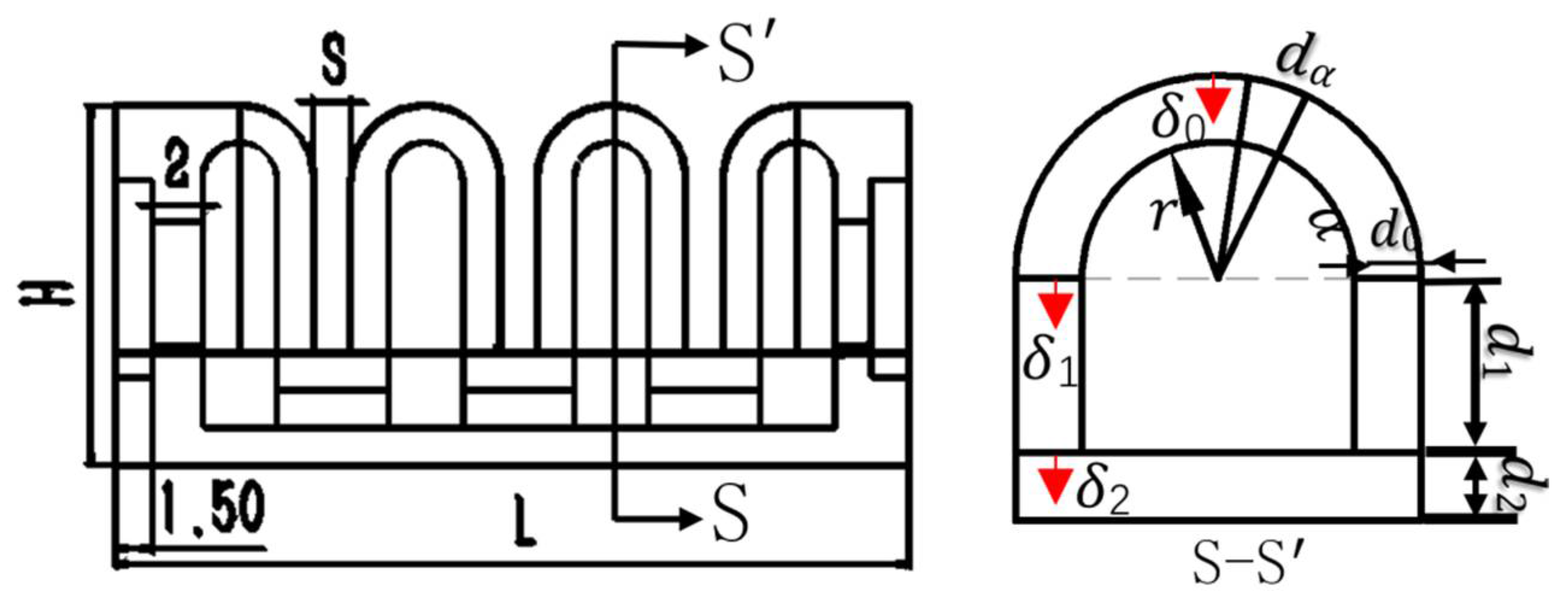
2.1. Finger Structure Design

In the structure of the human hand, the multi-joint finger structure makes the human hand more flexible. In addition to the thumb, human fingers usually have three rotational joints: proximal phalangeal joints and two interphalangeal joints. The proximal phalanx joints can move independently, and the two interphalangeal joints can move together.
Based on the motion form of human fingers, this paper proposes a multi-joint rigid-flexible coupled human-like flexible finger, the structure of which is shown in Figure 1. The rigid skeleton (proximal connecting frame, inter-finger connecting frame, end face sealing cover) simulates the inner skeleton of human fingers and works together with the phalangeal joints to realize the bending action of human fingers.
Figure 2 shows the structure of the soft finger components. Figure 2a shows the proximal phalanx joint. As an independent driving joint, it is composed of four cavities with an equiangular distribution of 90°. It can independently control the single cavity and multiple cavities to achieve multi-directional bending. The middle and distal phalanx joints are shown in Figure 2b, c. They are connected by the interdigital joint in Figure 2d. It adopts the same cavity channel and is jointly driven by the same air pressure. Through the combined action of air pressure in the different chambers, the multi-joint motion of the human-like finger motion can be realized, and the flexibility of bionic fingers can be improved.

2.2. Humanoid Finger Making

The main process of the preparation of a multi-joint rigid-flexible soft-body bionic finger includes the following steps:
  • preparation of cartilage joint of middle phalanx and distal phalanx;
  • preparation of proximal phalanx joint;
  • 3D printing of connecting skeleton;
  • assembly of soft-body bionic finger.
The specific steps are shown in Figure 3. First, we used a 3D printer to make each joint air cavity mold, and then mixed the E620A silicone rubber A and B liquids at a ratio of 1:1. It was placed in a vacuum defoamer to remove residual air bubbles, and then the prepared silica gel solution was slowly poured into the air cavity mold and allowed to stand at room temperature for 4 h. After demolding, the driver joints were sealed and a mesh fiber strain limiting layer was embedded on the lower surface of the driver to limit the axial elongation of the driver.

3. Mathematical Model and Simulation Analysis

For the analysis of the proposed soft-body finger bending deformation mechanism in this paper, the balance equation between the driving torque and the impedance torque of the software finger is established, and the relationship between the input positive air pressure and the bending angle of the finger is analyzed.

3.1. Movement Principle

The motion principle of the proximal phalanx joint is shown in Figure 4. When a positive pressure load is applied to one of the air chambers, the internal silicone body has low ductility and acts as a strain limiting layer, which causes anisotropic deformation of the proximal phalanx joint structure and bending action. The bending motion of the proximal phalanx joint is realized by utilizing the pressure difference of the gas introduced into each chamber.
The movement principle of the middle/distal phalanx joint is shown in Figure 5. The middle phalanx joint is composed of four air chambers (the distal phalanx joint is composed of three air chambers, and the structure is similar to that of the middle phalanx joint). When the soft body moves like a human finger, the positive pressure gas flows into the gas chamber. The flexural motion of the phalangeal joint is generated by anisotropic deformation by utilizing the expansion of the air cavity of the finger joint and the asymmetry of the bionic finger structure.

3.2. Yeoh Strain Energy Density Function Model

The bionic finger drive joint is mainly composed of a silicone rubber material, which has the characteristics of hyperelasticity and incompressibility. At present, the strain energy density function model is mainly used for theoretical analysis. Mainstream theoretical models include: Yeoh, Ogden [18], Mooney-Rivlin [19] and other categories. The Yeoh model is suitable for the nonlinear change in the large deformation behavior of silicone rubber materials [20]. In this paper, the second-order Yeoh model is used to establish a mathematical model of bionic finger kinematics. The establishment of this mathematical model is based on the following assumptions [21]:
  • The silicone rubber material is isotropic and incompressible.
  • The strain limiting layer used is not extensible.
  • Under the constraint of the strain limiting layer, the width and height of the driver remain unchanged during the deformation of the driver joint.
According to the Yeoh model, the strain energy density function ω is determined by the following equations
  ω = ω ( I 1 , I 2 , I 3 )
                      I 1 = λ 1 2 + λ 2 2 + λ 3 2 I 2 = λ 1 2 λ 2 2 + λ 2 2 λ 3 2 + λ 3 2 λ 1 2 I 3 = λ 1 2 λ 2 2 λ 3 2 }
where ω strain energy density function, I i , represents the strain tensor in three directions and λ i represents the main elongation ratio in three directions.
Based on the assumptions 1 and 3 of the mathematical model, it can be seen that
I 3 = λ 1 2 λ 2 2 λ 3 2 = 1 ,         λ 2 = 1 ;     I 1 = I 3 = λ 1 2 + λ 2 2 + 1  
This paper adopts the second-order Yeoh model strain energy density function
ω = C 10 ( I 1 3 ) + C 20 ( I 2 3 ) 2  
where C 10   and   C 20 indicate the material parameters
In this paper, the silicone rubber material E620A is used, and its material properties are shown in Table 1.
According to assumption 3, in order to simplify the model, the axial stress σ 1 can be regarded as the only principal stress. It takes the partial derivative of Equation (3) and shows the relationship between the available stress and elastic strain energy. By simplifying and ignoring the tiny quantities in the formula, we obtain
σ = 8 C 10 ( λ 1 1 )  

3.3. Theoretical Analysis on Bending Deformation of Soft Bionic Fingers

In order to study the relationship between the air pressure load and the bending deformation angle of the bionic finger interphalangeal joint, the finger joint cavity structure was taken as the research object. As shown in Figure 6, when the finger is subjected to a positive air pressure load, due to the asymmetry of the cavity structure, anisotropic bending deformation occurs in the finger joint. During the whole bending deformation process, the deformation in the axial direction is obvious.
During the rotation of the interphalangeal joint, the main factors affecting the bending deformation of the driver are the inner surface torque M p of the driver and the impedance torque M θ generated by the internal stress of the driver deformation. The moment M p is expressed as
M p = 2 p 0 π 2 0 r ( r s i n θ + d 1 + d 2 ) r d r d θ + 2 p 0 d 1 r ( y + d 2 ) d y  
where M p is the torque generated by the input air pressure, p is the input air pressure, d 1 is the rectangular chamber height, d 2 is the bottom thickness of the air cavity, y is the vertical distance between the rectangular chamber and the upper surface of the bottom of the driver, r is the inner diameter of the air cavity and θ is the air cavity bending angle.
The inner wall of the air cavity is deformed during the bending process of the finger, which causes the driver to generate an impedance torque M θ .
M θ = M σ 0 + M σ 1 + M σ 2  
where M σ 0 is the top resistance moment, M σ 1 is the intermediate resistance moment and M σ 2 is the bottom impedance moment.
The axial stretch ratio of each part is λ δ i   ( i = 0 , 1 , 2 )
λ δ 0 = ( r + δ 0 ) s i n α + d 1 + d 2 + R R = θ ( ( r + δ 0 ) s i n α + d 1 + d 2 ) + L L  
λ δ 1 = δ 1 + d 2 + R R = θ ( δ 1 + d 2 ) + L L
λ δ 2 = δ 2 + R R = θ δ 2 + L L
where L is the air cavity length, R is the bend radius of curvature, λ δ i is the elongation and δ i is the section thickness.
M σ 0 = 0 π 0 d 0 σ δ 0 ( ( r + d 0 δ 0 ) sin α + d 1 + d 2 ) ( r + d 0 δ 0 ) d δ 0 d α  
M σ 1 = 2 0 d 1 σ δ 1 ( r + d 0 ) ( d 1 + d 2 δ 1 ) d δ 1
M δ 2 = 2 0 d 2 σ δ 2 ( r + d 0 ) ( d 2 δ 2 ) d δ 2
According to the principle of virtual work, it is assumed that the gas pressure on the object is all converted into its internal stress, that is M p = M θ .
When the air pressure acts on the inner wall of the air cavity of the soft bionic hand joint, due to the deformation of the inner wall of the air cavity, the distribution of the real air pressure moment will be uneven and change. Therefore, the coefficient k is set to represent the changing air pressure moment.
{ M p = k M P k = f ( P )  
where M p is the true variation in air pressure moment.
We substitute Equations (10)–(12) into Equation (6) and combine Equations (5) and (6) to obtain the relationship between the input air pressure P and the finger actuator angle θ through numerical integration.

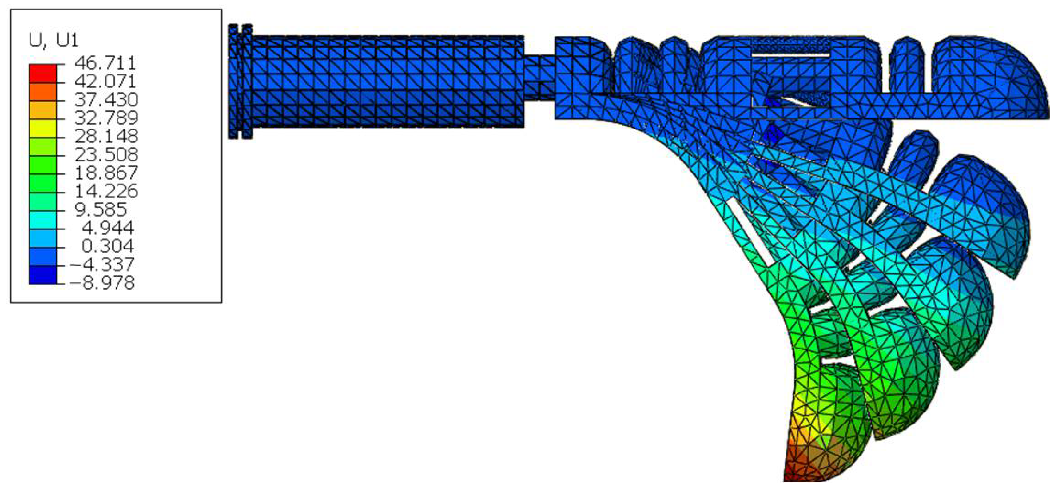
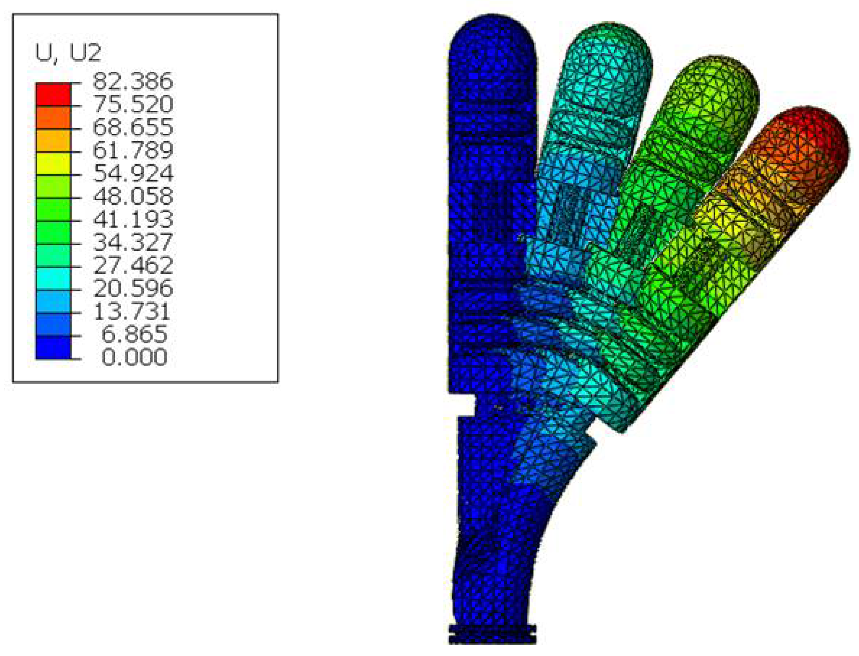
3.4. Simulation Analysis

In order to verify the correctness of the established theoretical model and visually display the bending deformation characteristics of the bionic hand, the Abaqus software was used to simulate and analyze the actuators with different structural parameters. The Yeoh model is used to characterize the elastic mechanical behavior of the joint actuator. Table 2 shows the two material parameters C 10 and C 20 . Table 3 shows the rigid frame and radially constrained fiber parameters, of which the radially constrained fiber cross section r = 0.03   mm .
During the simulation analysis of the bionic finger, the boundary conditions were set to be completely fixed for the air inlet. The air pressure range is 0–60 kPa. When the soft finger is stable, the bending shape is recorded. The simulation results of the independent drive are shown in Figure 7.
As shown in Figure 8, a pneumatic load is applied to the single cavity of the proximal phalanx joint, and the proximal phalanx joint can produce a bending and side swinging action.

3.5. Influence of Structural Parameters on Bending Deformation

The bending angle of the pneumatic finger is affected by structural parameters such as the wall thickness of the air cavity and the thickness of the strain layer. The specific structural parameters are shown in Figure 9 and Table 4.

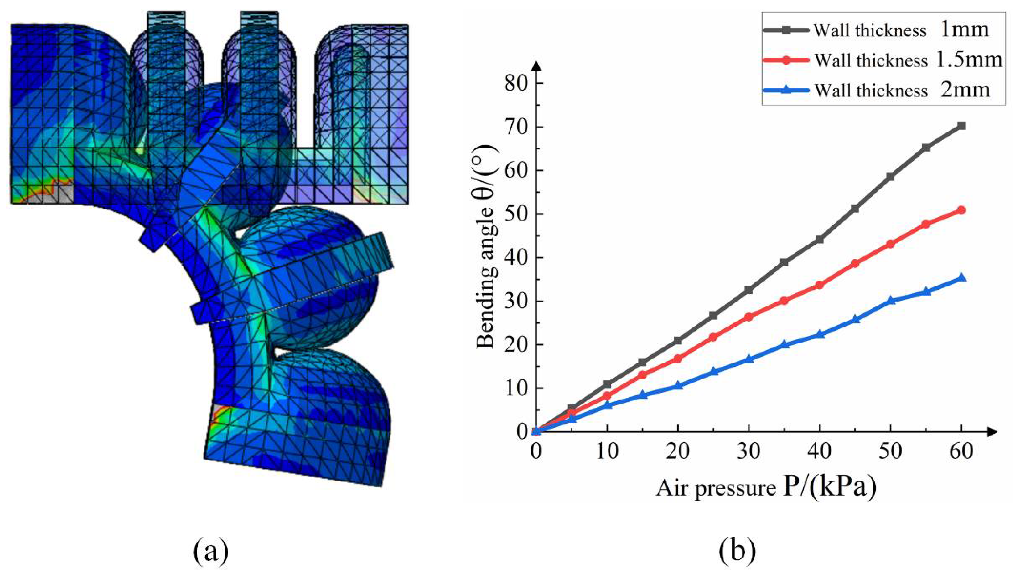
3.5.1. Influence of Air Cavity Wall Thickness on Bending

According to the simulation results, we analyze the relationship between the air pressure load and bending angle of the interphalangeal joint with different parameters. Figure 10b shows the relationship between the influence of the air cavity wall thickness of the middle phalangeal joint. With other conditions unchanged, the bending angle is gradually reduced with the increase in the air cavity wall thickness. When the wall thickness of the air cavity increases from 1 mm to 1.5 mm, the bending angle of the air cavity decreases by about 21.9%.

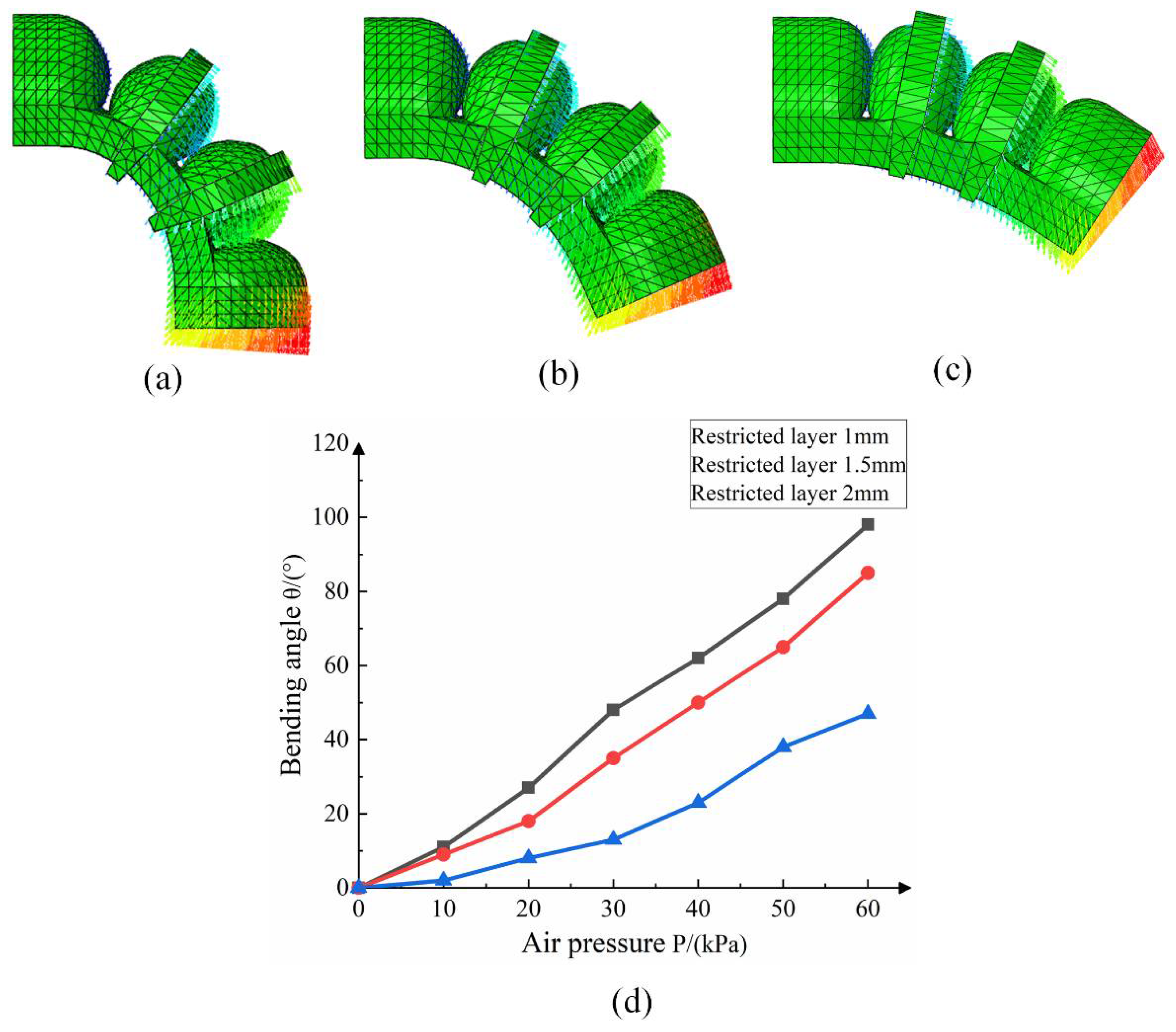
3.5.2. The Effect of Limiting Layer Thickness on Bending

The thickness of the bottom confinement layer has a great influence on the bending performance of the joint driver, and the confinement fiber is selected for the confinement layer. In this paper, the middle phalanx joint driver is taken as the research object, and the bending simulation of the driver joint is carried out by confining layers of different thicknesses. The simulation analysis results are shown in Figure 11.
The result analysis shows that the thicker the confinement layer, the greater the influence on the bending angle of the drive joint. Under the same air pressure, the smaller the wall thickness, the greater the deformation of the finger joint driver. The main reason is that during the movement of the soft-body driver, the joint air cavity absorbs energy to overcome the wall thickness bending and generates resistance torque. The smaller the wall thickness, the less energy it needs to absorb, and the main energy is used for the bending and deformation of the air cavity. The effect of the thickness of the confinement layer on the bending angle of the finger is smaller than that of the air cavity wall thickness.
In order to show the bending deformation effect of the actuator more specifically, the deformation of the terminal coordinates when the interphalangeal joint is bent is studied. As shown in Figure 12, the soft finger with the air cavity wall thickness of 1.5 mm and the confinement layer thickness of 1.5 mm was used as the research object, and the specific shape coordinates of the soft finger bending under different air pressure loads are shown.

4. Experiment

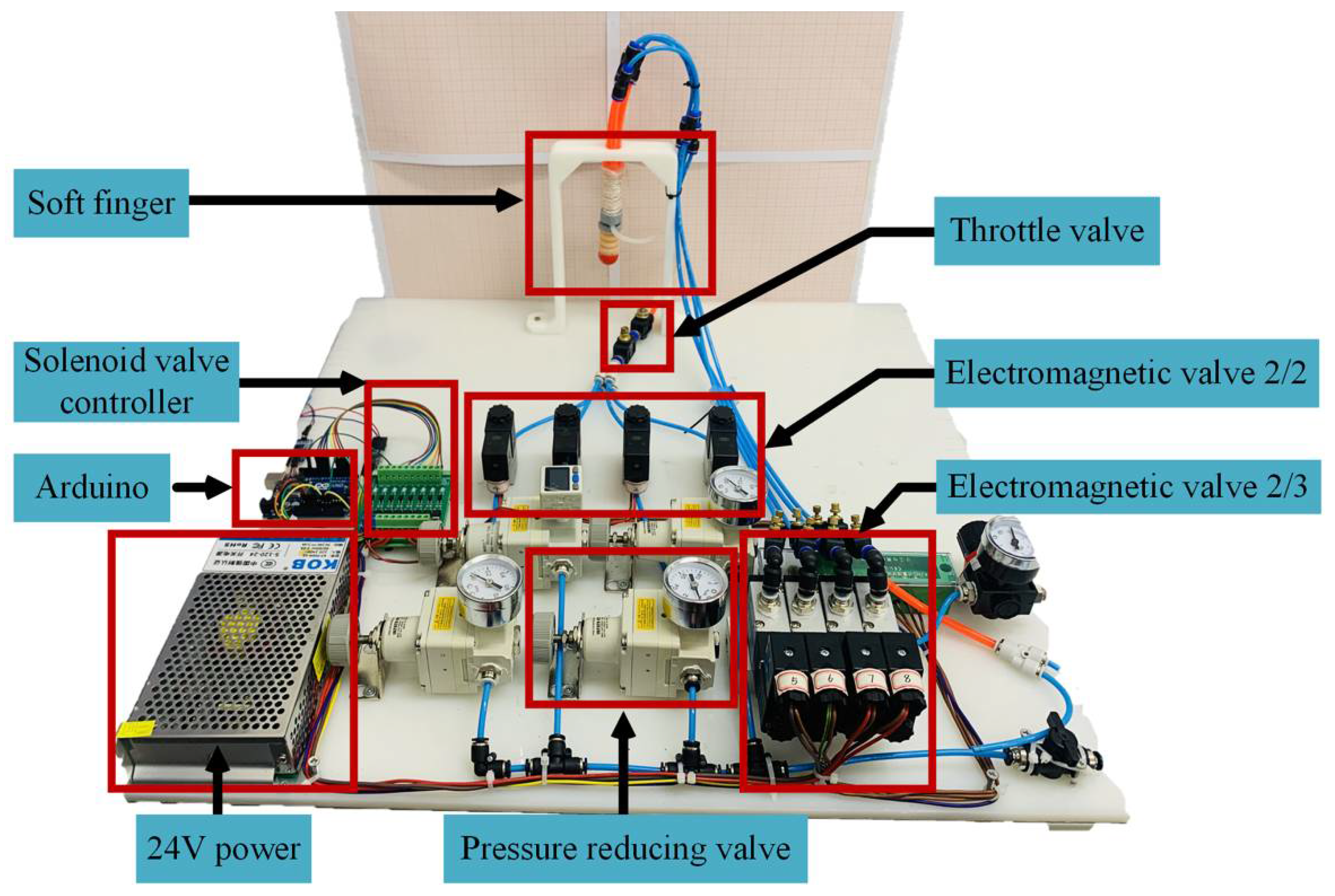
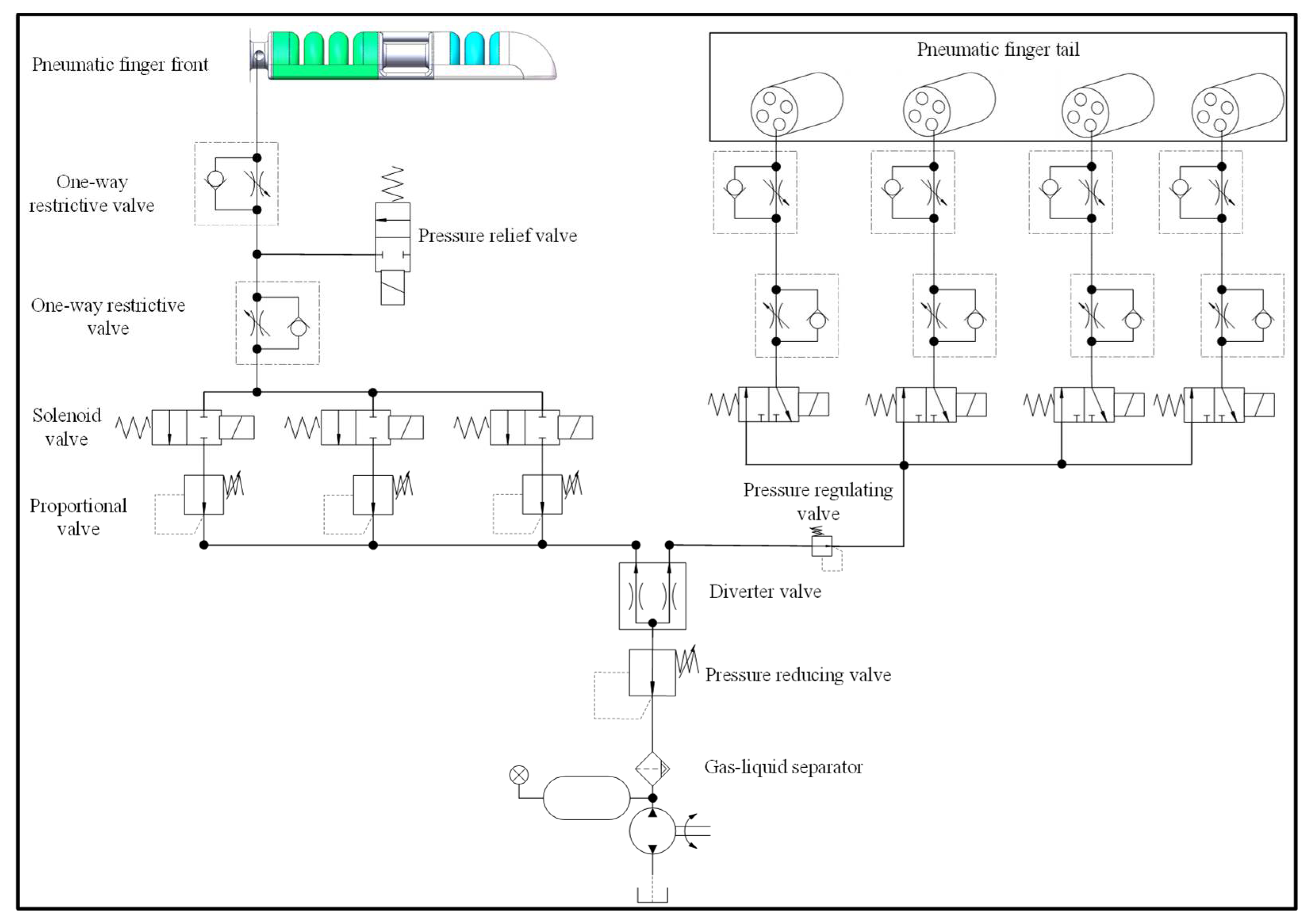
4.1. Experimental Platform and Method

In order to further verify the correctness of the theoretical model and the finite element analysis model, according to the post-processing results of the finite element analysis, this paper adopts the size parameters of the air cavity wall thickness of 1.5 mm and the bottom confinement layer thickness of 1.5 mm. A soft finger was fabricated, and an experimental study on the bending characteristics of the actuator was carried out. Figure 13 shows the experimental platform of the device, in which the pressure regulating valve is used to control the input air pressure value, and the throttle valve controls the output air flow rate. Figure 14 shows the schematic diagram of the pneumatic control of the device. In order to control the flow rate and air pressure, a combination of a throttle valve and a solenoid valve is used to complete the finger bending performance test.

4.2. Bending Capacity Analysis

4.2.1. Analysis of Bending Performance of Interphalangeal Joints

The soft finger bending angle is an important index to evaluate finger performance. In the measurement of the bionic finger bending experiment, the output gas pressure was changed in the range of 0–60 kPa. Figure 15a shows the results of the bending and deformation of the soft bionic finger under different air pressures. The initial position of the finger of the soft body was selected as the reference point, and the bending angle θ of the joint driver was measured under different air pressures.
From Equation (13), it is known that the gain coefficient k is a dynamic coefficient related to the air pressure load P to represent the change in the real air pressure moment. Comparing the corrected theoretical curve with the experimental data, the results are shown in Figure 15b. After correction, the theoretical curve and the experimental curve have an average deviation of 6.5°. The main reason is that in the process of making soft fingers, the internal bubbles cannot be completely removed, so the stress will be unevenly distributed during the deformation process of the soft fingers. In the range of the air pressure load of 0–45 kPa, the soft-body finger produces nonlinear changes. With the increase in air pressure load, the angle of the soft-body joint increases. Under the air pressure load of 60 kPa, the maximum bending angle of the soft-body finger is about 71°.
In order to verify the performance difference between the rigid-flexible coupled finger and the pure soft finger, a pure soft finger, as shown in Figure 16a, was fabricated. The experimental results show that the inter-finger load force of the soft finger and the air pressure load show a nonlinear change. When the air pressure load is 0–60 kPa, the fingertip bearing capacity of the rigid-flexible coupling finger is increased by 63.13% on average. When the external load is 60 kPa, the designed rigid-flex structure fingertip bearing capacity is 1.51 N, the pure soft structure fingertip bearing capacity is 1.12 N and the fingertip bearing capacity is increased by 34.8%.

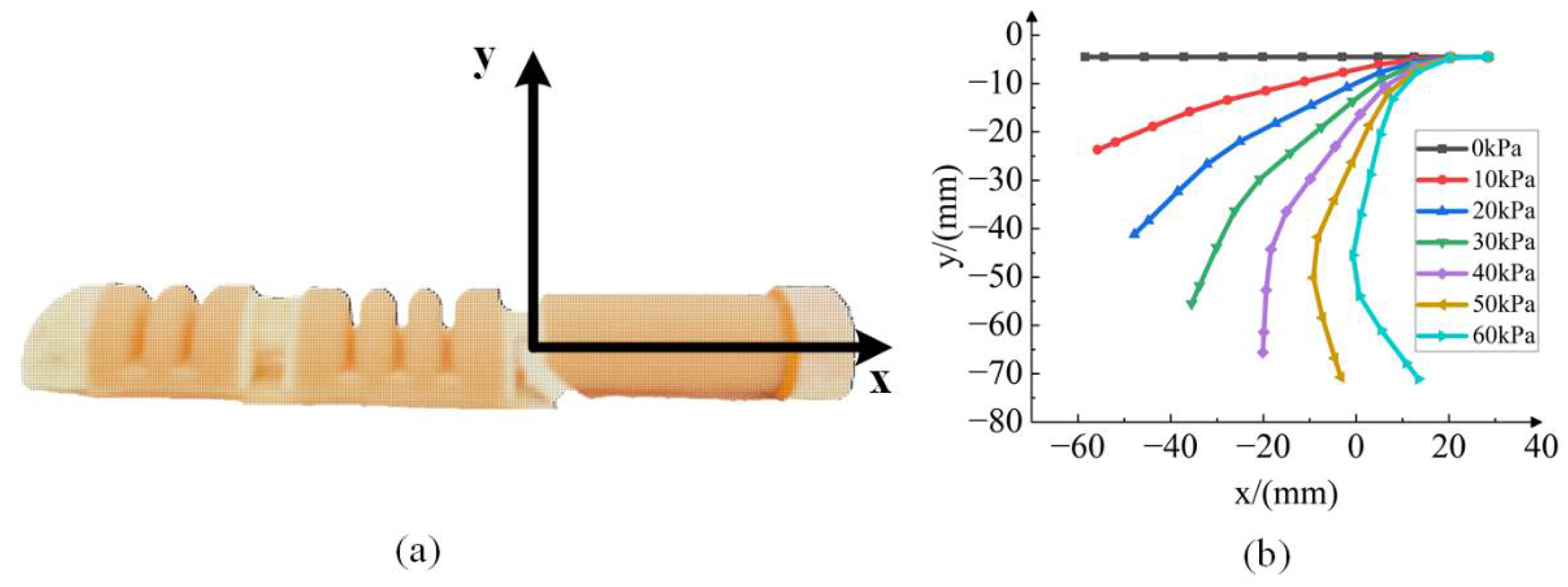
4.2.2. Analysis of Bending Performance of Proximal Phalangeal Joint

Figure 17a shows the bending deformation diagram of the single cavity of the bionic finger’s proximal phalanx joint under the air pressure of 0–200 kPa. As shown in Figure 17b, in the range of 0–100 kPa, the bending angle of the proximal phalanx joint varies less with the increase in the air pressure load because the inner radius of the air cavity hole is small (1 mm) and the radius of the confinement layer (3.5 mm) is too large. In the initial bending action, the impedance moment of the central confinement layer needs to be overcome so that the bending angle does not change significantly. On the whole, there is a nonlinear change between the bending angle and the pressure load. By applying different air pressure loads in different chambers, the omnidirectional bending action of the proximal phalangeal joint can be realized.

5. Conclusions

In this paper, to solve the problem of the low bearing capacity of pure soft bionic fingers, a design scheme of multi-joint rigid-flexible coupling humanoid fingers is proposed. We conduct simulation and experimental analysis of soft finger performance.
According to the movement mode of human fingers, a rigid-flexible coupling multi-joint soft bionic finger structure is proposed and prepared, which can realize the joint bending action of soft fingers and the rotation and bending functions of human fingers. According to the movement mode of human fingers, a rigid-flexible coupled multi-joint soft bionic finger structure is proposed and prepared, which can realize the joint bending action of soft fingers and the rotation and bending functions of human-like fingers. In this paper, the second-order Yeoh theoretical model and the moment balance equation are used to establish a theoretical model of the bending deformation of the proximal phalangeal joint and the interphalangeal joint. The statics results of the Abaqus CAE simulation software are analyzed, and the bending performance of soft fingers under different structural parameters is analyzed, which provides a theoretical basis for the selection of experimental parameters. The theoretical model–simulation–experimental results of humanoid finger bending deformation were verified to be consistent, and the bearing capacity of rigid-flexible coupled bionic fingers was verified by comparison. Compared with pure soft bionic fingers, the average fingertip bearing capacity of 0–60 kPa increased by 63.13%.
This paper provides research ideas and methods for the study of a rigid-flexible coupling soft human hand, and provides a solution to the problem of the constant curvature rotation of a soft bionic hand. The research results show that the articulated rigid-flexible coupling soft humanoid finger proposed in this paper can simulate the movement of human fingers and improve the bearing capacity of the fingertip, which has a certain practical application value.

Author Contributions

Conceptualization, C.C. and L.W.; methodology, G.C.; software, H.S.; validation, J.S., L.W. and C.C.; formal analysis, Y.L. and R.X.; investigation, G.C. and Y.L.; data curation, L.W.; writing—original draft preparation, J.S. and L.W.; writing—review and editing, J.S., C.C. and R.X.; supervision, M.X.; project administration, J.S.; funding acquisition, M.X. and R.X. All authors have read and agreed to the published version of the manuscript.

Funding

This research was supported by the National Natural Science Foundation of China (Grant No. 51975171 and Grant No. 51805128), Key Research and Development Projects in Zhejiang Province of China (No.2020C01061).

Institutional Review Board Statement

Not applicable.

Informed Consent Statement

Not applicable.

Data Availability Statement

Not applicable.

Conflicts of Interest

The authors declare no conflict of interest.

References

  1. Guan, Q.; Sun, J.; Liu, Y.; Wereley, N.M.; Leng, J. Novel Bending and Helical Extensile/Contractile Pneumatic Artificial Muscles Inspired by Elephant Trunk. Soft Robot. 2020, 7, 597–614. [Google Scholar] [CrossRef] [PubMed]
  2. Chen, C.; Sun, J.; Wang, L.; Chen, G.; Xu, M.; Ni, J.; Ramli, R.; Su, S.; Chu, C. Pneumatic Bionic Hand with Rigid-Flexible Coupling Structure. Materials 2022, 15, 1358. [Google Scholar] [CrossRef]
  3. Guan, Q.H.; Sun, J.; Liu, Y.J.; Leng, J. Status of and trends in soft pneumatic robotics. Sci. Sin. Technol. 2020, 50, 897–934. [Google Scholar]
  4. Hu, Y.; Li, J.; Chen, Y.; Wang, Q.; Chi, C.; Zhang, H.; Gao, Q.; Lan, Y.; Li, Z.; Mu, Z. Design and Control of a Highly Redundant Rigid-Flexible Coupling Robot to Assist the COVID-19 Oropharyngeal-Swab Sampling. IEEE Robot. Autom. Lett. 2021, 7, 1856–1863. [Google Scholar] [CrossRef] [PubMed]
  5. Wattanasiri, P.; Tangpornprasert, P.; Virulsri, C. Design of Multi-Grip Patterns Prosthetic Hand with Single Actuator. IEEE Trans. Neural Syst. Rehabil. Eng. 2018, 26, 1188–1198. [Google Scholar] [CrossRef] [PubMed]
  6. Zhou, J.; Chen, X.; Chang, U.; Lu, J.; Leung, C.; Chen, Y.; Hu, Y.; Wang, Z. A Soft-Robotic Approach to Anthropomorphic Robotic Hand Dexterity. IEEE Access 2019, 7, 1. [Google Scholar] [CrossRef]
  7. Zhou, J.; Shu, C.; Zheng, W. A Soft-Robotic Gripper With Enhanced Object Adaptation and Grasping Reliability. IEEE Robot. Autom. Lett. 2017, 2, 2287–22931. [Google Scholar] [CrossRef]
  8. Hardman, D.; Thuruthel, T.G.; Iida, F. Self-healing ionic gelatin/glycerol hydrogels for strain sensing applications. NPG Asia Mater. 2022, 14, 11. [Google Scholar] [CrossRef]
  9. Liu, S.; Wang, F.; Liu, Z.; Zhang, W.; Zhang, D. A Two-Finger Soft-Robotic Gripper With Enveloping and Pinching Grasping Modes. IEEE/ASME Trans. Mechatron. 2020, 26, 146–155. [Google Scholar] [CrossRef]
  10. Jing, X.; Chen, S.; Zhang, C.; Xie, F. Increasing Bending Performance of Soft Actuator by Silicon Rubbers of Multiple Hardness. Machines 2022, 10, 272. [Google Scholar] [CrossRef]
  11. Ming, X.; Guan, W.; Cheng, R. Fiber-reinforced flexible joint actuator for soft arthropod robots. Sens. Actuators A Phys. 2022, 340, 113522. [Google Scholar] [CrossRef]
  12. Chen, F.; Miao, Y.; Zhang, L.; Chen, S.; Zhu, X. Triply Periodic Channels Enable Soft Pneumatic Linear Actuator with Single Material and Scalability. IEEE Robot. Autom. Lett. 2022, 7, 2668–2675. [Google Scholar] [CrossRef]
  13. Huang, W.; Xiao, J.; Xu, Z. A variable structure pneumatic soft robot. Sci. Rep. 2020, 10, 18778. [Google Scholar] [CrossRef]
  14. Xie, Z.; Domel, A.G.; An, N.; Green, C.; Wen, L. Octopus Arm-Inspired Tapered Soft Actuators with Suckers for Improved Grasping. Soft Robot 2020, 7, 639–648. [Google Scholar] [CrossRef]
  15. Zhao, Y.; Shan, Y.; Guo, K.; Qi, L.; Yu, H. A soft continuum robot, with a large variable-stiffness range, based on jamming. Bioinspir. Biomim. 2019, 14, 66007. [Google Scholar] [CrossRef]
  16. Ge, L.; Chen, F.; Wang, D.; Zhang, Y.; Gu, G. Design, Modeling, and Evaluation of Fabric-Based Pneumatic Actuators for Soft Wearable Assistive Gloves. Soft Robot 2020, 7, 583–596. [Google Scholar] [CrossRef]
  17. Zhang, G.; Li, S.; Wu, Y.; Zhu, M. An Investigation on the Grasping Position Optimization-Based Control for Industrial Soft Robot Manipulator. Machines 2021, 9, 363. [Google Scholar] [CrossRef]
  18. Ogden, R.W. Large Deformation Isotropic Elasticity: On the Correlation of Theory and Experiment for Compressible Rubberlike Solids. Proc. R. Soc. A Math. Phys. Eng. Sci. 1972, 328, 567–583. [Google Scholar] [CrossRef]
  19. Saunders, R.S.R.W. Large Elastic Deformations of Isotropic Materials. VII. Experiments on the Deformation of Rubber. Philos. Trans. R. Soc. London. Ser. A Math. Phys. Sci. 1951, 243, 251–288. [Google Scholar] [CrossRef]
  20. Huang, J.; Xie, G.; Liu, Z. Finite Element Analysis of Hyperelastic Rubber Materials Based on Mooney-Rivlin Model and Yeoh Model. Rubber Ind. 2008, 55, 467–471. [Google Scholar] [CrossRef]
  21. Polygerinos, P.; Zheng, W.; Overvelde, J.; Galloway, K.C.; Walsh, C.J. Modeling of Soft Fiber-Reinforced Bending Actuators. IEEE T Robot 2015, 31, 778–789. [Google Scholar] [CrossRef] [Green Version]
Figure 1. The structure of soft finger.
Machines 10 00448 g001
Figure 2. The various parts of the multi-joint soft finger: (a) proximal phalanx joint structure; (b) middle phalanx joint structure; (c) distal phalanx joint structure; (d) connecting frame (1—interdigital joint frame, 2—proximal joint frame, 3—face sealing cover, 4—fingertip).
Machines 10 00448 g002
Figure 3. Software bionic finger preparation process: (a) the production process of the middle phalanx joint; (b) the production process of the distal phalanx joint; (c) the production process of the proximal phalanx joint; (d) the connecting frame; (e) the figure assembly.
Machines 10 00448 g003
Figure 4. The bend of proximal phalangeal joint.
Machines 10 00448 g004
Figure 5. The middle finger joint structure.
Machines 10 00448 g005
Figure 6. The bending diagram middle finger joint.
Machines 10 00448 g006
Figure 7. Curved shape of interphalangeal joint drive.
Machines 10 00448 g007
Figure 8. Proximal phalangeal joint curved shape.
Machines 10 00448 g008
Figure 9. Soft finger structure.
Machines 10 00448 g009
Figure 10. (a) Schematic diagram of joint bending simulation; (b) effect of different air cavity wall thickness on bending performance.
Machines 10 00448 g010
Figure 11. Analysis of the influence of the thickness of the confinement layer on the bending properties. (a) Confinement layer 1 mm; (b) confinement layer 1.5 mm; (c) confinement layer 2 mm; (d) comparison of the influence of different confinement layer thicknesses on bending properties.
Machines 10 00448 g011
Figure 12. (a) x–y plane coordinate system virtual partition; (b) finger bending shape under different air pressures.
Machines 10 00448 g012
Figure 13. Soft finger bending experiment device.
Machines 10 00448 g013
Figure 14. Pneumatic control schematic.
Machines 10 00448 g014
Figure 15. (a) Bending deformation state of fingers under different loads; (b) bending angle comparison curve after correction.
Machines 10 00448 g015
Figure 16. Comparison experiment of soft finger interphalangeal joint: (a) pure soft fingers, (b) test comparison.
Machines 10 00448 g016
Figure 17. Bending performance of proximal phalangeal joint: (a) different air pressure finger bending angle, (b) test bending angle curve.
Machines 10 00448 g017
Table 1. E620A silica gel performance parameters.
ParameterNumber
Hardness (A)20 ± 2
Tensile strength (Mpa)6.5
Tear strength (kN/m)28 ± 2
Curing time (h)4
Table 2. Yeoh model parameters.
ParameterNumber
C 10 0.072
C 20 0.0025
Table 3. Model parameters.
NameMaterialElastic Modulus (Mpa)Poisson Ratio
connection frameABS plastic22000.394
constrained fiberselastic material31,0760.36
Table 4. Soft finger structure parameters.
Parameters H L S r d 0 d 1 d 2
Number (mm)14.5321.51.51.5102
Publisher’s Note: MDPI stays neutral with regard to jurisdictional claims in published maps and institutional affiliations.

