Abstract
The rock-breaking efficiency of a drilling tool directly affects the production costs and progress of foundation construction. It is essential to understand the mechanism of mechanical rock-breaking to improve rock-breaking efficiency. In this study, dynamic rock-breaking simulation research was carried out on a drill bit and was based on the LS-DYNA simulation platform. Additionally, the influence of the rotational speed of the spindle and the feed rate on the force of the drill bit in the rock-breaking process was obtained. The influence of the rotational speed of the spindle and the feed rate on drill vibration was also analyzed. The content of the presented theoretical and simulation research was verified through experiments. The following conclusions were drawn: first, the reaction force that rock has on the drill bit presents a law according to different rock types and drilling process parameters. With the increase in rotational speed, the axial reaction force decreases. With the increase in the feed rate, the axial reaction force increases. The effect of rock type on axial reaction force is nonlinear. Second, the influence of the spindle rotational speed and feed rate on the vibration of the drill bit also presents a law during rock-breaking. When the feed amount is constant, the transverse vibration slows down, and the axial vibration intensifies as the rotational speed increases. When the rotational speed is constant, as the feed increases, the transverse vibration slows down and the axial vibration intensifies. The research results provide a theoretical basis for selecting drilling process parameters and for improving rock-breaking efficiency.
1. Introduction
There are several rock-breaking tools that are available for different engineering needs, such as oil drilling, geological exploration, and bolt installation [1]. The rotary drill plays an essential role in the day-to-day construction of infrastructure, such as the construction of bridges, houses, power transmission towers, and other infrastructure. During the drilling process of rotary drilling rigs, the power head causes the drill pipe and drill bit to rotate. Rock-breaking is carried out with cutting tools that have been installed on the bottom and sides of the drilling bucket. The rock-breaking efficiency of a rotary drill is related to the progress of the project and the level of production cost. Therefore, to improve its rock-breaking efficiency, it is essential to study the rotary drill’s rock-breaking mechanism. This type of research is both less and more difficult due to the limitations of test costs and cycles. Several attempts have been made, with many theoretical and experimental research experiments having been carried out on polycrystalline diamond compact bits to improve their rock-breaking efficiency [2,3,4]. However, there is little research on the rotary’s rock-breaking mechanism and on the down-the-hole drill bit. Therefore, further improvements are required.
He Zhenguo et al. conducted a simulation study of single-tooth-cut broken rock and determined the quantitative relationship between the cutting load and cutting depth [5]. They also studied the mechanism by which stick–slip vibrations occur. Liu Bo et al. established an interaction force model between the percussion bit and rock by conducting the finite element analysis of the rock-breaking mechanism through rotary percussion drilling [6]. At the same time, they analyzed the effect of the rotational speed and the impact frequency on the rock-breaking efficiency. Liu Biao et al. used the discrete element method to simulate the cutting effect of PDC teeth under different cutting speeds, cutting angles, cutting depths, and confining pressure parameters and determined the law of cutting force changing during the development of PDC teeth and rock cracks [7]. Liu Shubin et al. established a rock-breaking analysis model using impact cutting in which one-dimensional and multidimensional impact actions were regarded as single-tooth impact problems with different angles [8]. The damage evolution and debris formation process of rocks under axial torsional and multidimensional impact actions were discussed using the finite element method, and the impact angle range was calculated and analyzed from 0° to 90°. The simulation results are verified using field tests. Lu Zongyu et al. designed an ultrasonic vibration generation sub, built an ultrasonic rock-breaking simulation test bench, and carried out an ultrasonic rock-breaking speed test, as well as experiments affecting the ultrasonic rock-breaking efficiency [9]. Based on the discrete element particle flow method, Zhu Xiaohua et al. established a numerical model of black sandstone with microscopic aggregation characteristics [10]. Błaż Sławomir et al. studied the laws of a single particle jet, a multi-particle jet, and assisted rock-cutting under different particle sizes, incident angles, and incident velocity conditions. Moreover, they studied the temperature and pressure resistance of drilling fluids at different oil–water ratios [11]. Wu Bisheng et al. performed transient analyses of the temperature and stress changes that take place in the wellbore and in the formation processes that take place during convection circulation [12].
Recently, most studies have focused on new rock-breaking methods, such as jet rock-breaking, using different media and nozzle structures and have achieved various results. Li Mukun et al. introduced a new rock fragmentation method that effectively combines pressure shock with thermal shock [13]. The results show that this method has a higher rock fragmentation efficiency than the water jet method. Liu Zenghui et al. investigated the dynamic characteristics of a roadheader for breaking rocks containing different numbers and sizes of predrill holes. [14]. Lu Yiyu et al. proposed a new rock-breaking technology that uses a water jet to drill tree-like holes in coal seams, designed a self-propelled water jet drilling nozzle for drilling, and carried out experimental verification tests [15]. They further studied the relationship between the physical parameters of the forward nozzle of the drill bit and the diameter and shape of the drilled holes and studied the effect of different physical parameters on rock-breaking efficiency through drilling experiments [16]. Wang Peng et al. considered pure cutting to be an effective auxiliary medium for rock-breaking and discussed the feasibility of rock-breaking using water jets for cutting from the two perspectives of cutting suction and rock-breaking efficiency [17]. Tang Yang et al. designed a straight rotating mixing nozzle [18]. Tang Qiongqiong et al. presented a rock-crushing mechanism that used ultrasonic vibration through numerical simulation and experimental research [19]. Rock-breaking efficiency can be improved by using ultrasonic vibration technology. Wang Wei et al. established a numerical model based on cohesion units and studied the rock-breaking mechanism under compound impact and dynamic impact tests [20]. They obtained the ranges for the optimal impact angle and duration. Shao Fangyuan et al. studied the rock-breaking mechanism of axe-shaped cutting teeth and found that the tool had better wear resistance and cutting efficiency [21]. Zhang Zengzeng et al. investigated the rock-breaking mechanism of corrugated PDC cutters and evaluated the rock-breaking efficiency based on the cutting force, cutting temperature, specific mechanical energy, and other dimensions [22]. Zhao Yang et al. investigated the rock-breaking mechanism while it was assisted by axial ultra-high frequency vibration (UHFV) during the drilling process from the four dimensions of the rock failure mode of the cutting force and specific mechanical energy and crack propagation process [23]. They effectively improved the rock-breaking efficiency by adjusting the excitation frequency. Knez Dariusz et al. studied the current developments in drilling outside of earth and explained the future of the technology [24]. Yu Guangdong et al. proposed a method to optimize drilling speed [25]. Liu Qingyun et al. proposed an adaptive control strategy for an airborne bolter based on genetic algorithm optimization [26].
The existing research focuses on the rock, but there is little research on the drilling tool [27]. The rock-breaking process of the rotary bit consists of multiple single-tooth rock-breaking instances. Therefore, it is essential to establish a single-tooth rock-breaking analysis model. This study investigates the stress state of the drilling tool during the conventional rock-breaking process from three dimensions: theoretical analysis, finite element simulation, and experimental verification. First, the stress state of the drill bit in the rock-breaking process is analyzed theoretically. Second, a three-dimensional bit model is established that consists of the pick of the rotary and the impact bit. The percussion bit is established because it is also accompanied by the rotary cutting process. Third, the dynamic rock-breaking simulation research is carried out on the drill bit based on the LS-DYNA simulation platform using a vertical rock-breaking angle. Finally, the accuracy of the theoretical analysis and simulation research is verified by experiments, which supports improving the rock-breaking efficiency of the rotary drilling rig.
2. Force Analysis of Single-Tooth Vertical Rock-Breaking
According to the principle of rock interaction, all of the mechanical rock-breaking tools for drilling can be divided into three categories: cutting shear, chiseling crushing, and chiseling crushing shear. The shear strength of a rock joint or a jointed rock is considerably lower than the compressive strength [28]. Therefore, shear rock-breaking has a better effect. To obtain the smallest possible capacity, it should be broken fragmentarily. In order to deepen drilling evenly and to ensure the maximum crushing efficiency of rock-crushing tools, it is necessary to break the bottom of the well continuously.
The bit is subjected to the torque and feed force provided by the power source, shears the rock, and is subjected to the reaction force. The reaction forces can be decomposed into axial, lateral, and tangential forces. It is the teeth of the drill bit that directly interact with the rock. Thus, studying the rock-breaking mechanism should start by analyzing the single-tooth rock-breaking method.
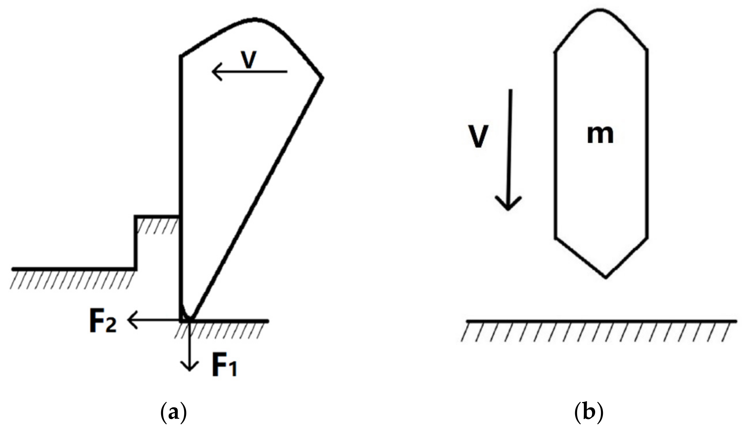
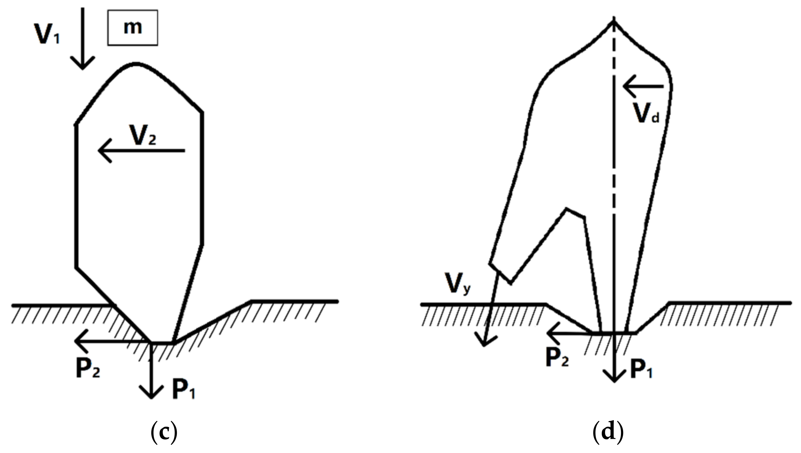
Figure 1 shows the interaction of the cutting tool with the rock. The cutting and shearing rock fragmentation processes can be divided into intrusive rock and cutting rock fragmentation processes, which act on a rock via axial and tangential loads.
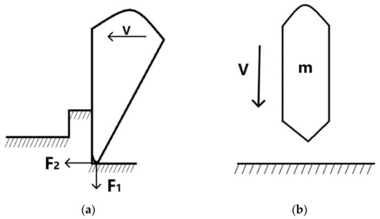
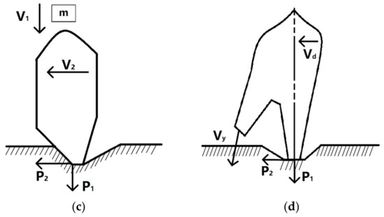
Figure 1.
Schematic of the drill rock blade with rock. (a) Cutting and shearing mode F1 is the axial force. F2 is the tangential force. V is the speed of the bit. (b) Chiseling crushing mode. m is the mass of the drill tool. V is the impact velocity. (c,d) Chiseling crushing shear mode. P1 is the axial force. P2 is the tangential force. V1 is the impact velocity. V2 is the forward speed of the bit. m is the mass of the drill tool. Vy is the velocity of adjacent teeth. Vd is the speed of the bit.
The interaction between the drill teeth and the rock is a very complicated and dynamic process. The different stages of the intrusion process can be described using different theories.
Elasticity studies show that the distribution of iso-stress lines in an elastic semi-infinite body is uniformly symmetrical when axial force acts on the head alone. When the axial and tangential forces act on it, the iso-stress line distribution is non-uniform and asymmetric. At the contact surface, compressive stress will occur in front of the tangential force.
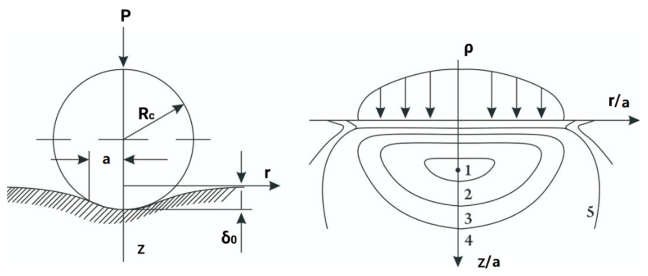
At present, the ends of the cutting tools used in hard and fractured rocks are often made into spherical teeth. For chisel shear rock-breaking tools, cutting and drilling are conducted through the spherical structure on the surface. When there is no load, the sphere makes contact with the solid surface at one point. As the load on the sphere increases, a circular contact surface is formed. Figure 2 shows the calculation diagram and pressure distribution of the sphere. The sharp edge can be regarded as an indenter whose radius of curvature is close to 0.
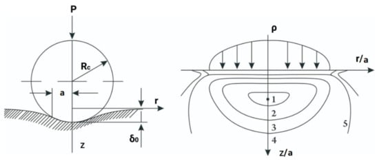
Figure 2.
Calculation diagram and pressure distribution of the ball in the case of pressing.
According to the Hertz theory [29], the maximum pressure at the center of the contact surface is determined by
In the formula, a represents the contact radius. It is determined by
In Formula (2), μ1 and μ2, respectively, represent the Poisson’s ratio between the pressure head and the rock. Rc is the radius of the sphere. P is the axial force. E1 and E2, respectively, represent the elastic modulus of the pressure head and the rock [30,31]. An analysis of the state of solid stress by P.M. Egeles shows that the stress field under the sphere has the same structure as that under a flat cylindrical head. However, the compression zone is smaller when the sphere is pressed than when pressing the flat cylindrical head. The maximum shear stress is located on the symmetry axis at a depth of about 0.5a from the contact surface and the pressure edge.
Most rock limit states occur outside of the pressure core of the first extreme zone during spheroid insertion. Annular cracks are formed in the first extreme zone. However, such cracks do not develop into deep cracks. When the extreme band on the symmetry axis reaches the limit state, the limit state region develops rapidly in all directions.
Under the action of a two-directional load, the rock crushing tool has the following characteristics:
(1) When the axial and tangential forces act together, they are regarded as exerting a certain angle of force. There is an optimal ratio or direction of force between the axial and tangential forces. This relationship varies for different rocks. When drilling different rocks, there should be reasonable coordination between the axial pressure and rotational speed.
(2) When the axial and tangential forces act together, an uneven stress state is produced in the rock beneath the crushing tool.
(3) When tensile stress occurs in rock, other things being equal, the rock will begin to break in the tensile stress zone at relatively low forces.
3. Finite Element Model and Convergence Verification of Single-Tooth Dynamic Rock-Breaking
First, the model was established using the SolidWorks simulation platform. Rock crushing using two drill bit types under axial force and torque was investigated using the Ansys Workbench finite element simulation platform. The rock-breaking carried out by the bit teeth is described.
Some assumptions can be made about the simulation model. Consider the rock as an isotropic continuous medium. Since the hardness of the drill bit is higher than that of the rock, it is treated as a rigid body. It should be noted that the anisotropy of the rock has a certain influence on its properties in practice [32,33]. The rock element was removed immediately after the failure, ignoring the impact of secondary cutting on continuous drilling.
The rocks in the model were 300 mm long, 300 mm wide, and 50 mm thick. For better verification during the test, the drill bit was set into the rock vertically [34]. The material of the drill tooth is outlined in Table 1 below.

Table 1.
Bit parameter setting.
The bit was set to be rigid during the cutting process because its cutters are harder than rock. MAT_RIGID material model # 20 was selected from the LS-DYNA material library, and the material parameters of the drill bits are presented in Table 1. The pick diameter was 60 mm. The radius of the carbide tip was 15 mm. The angle of carbide tip was 78.3°.
MAT_JOHNSON_HOLMQUIST_CONCRETE material model no. 111 from the LS-DYNA material library was chosen as the rock material. The parameters for the rock material are shown in Table 2.

Table 2.
Rock parameter settings.
3.1. Subsection-Defined Contact Types and Boundary Conditions
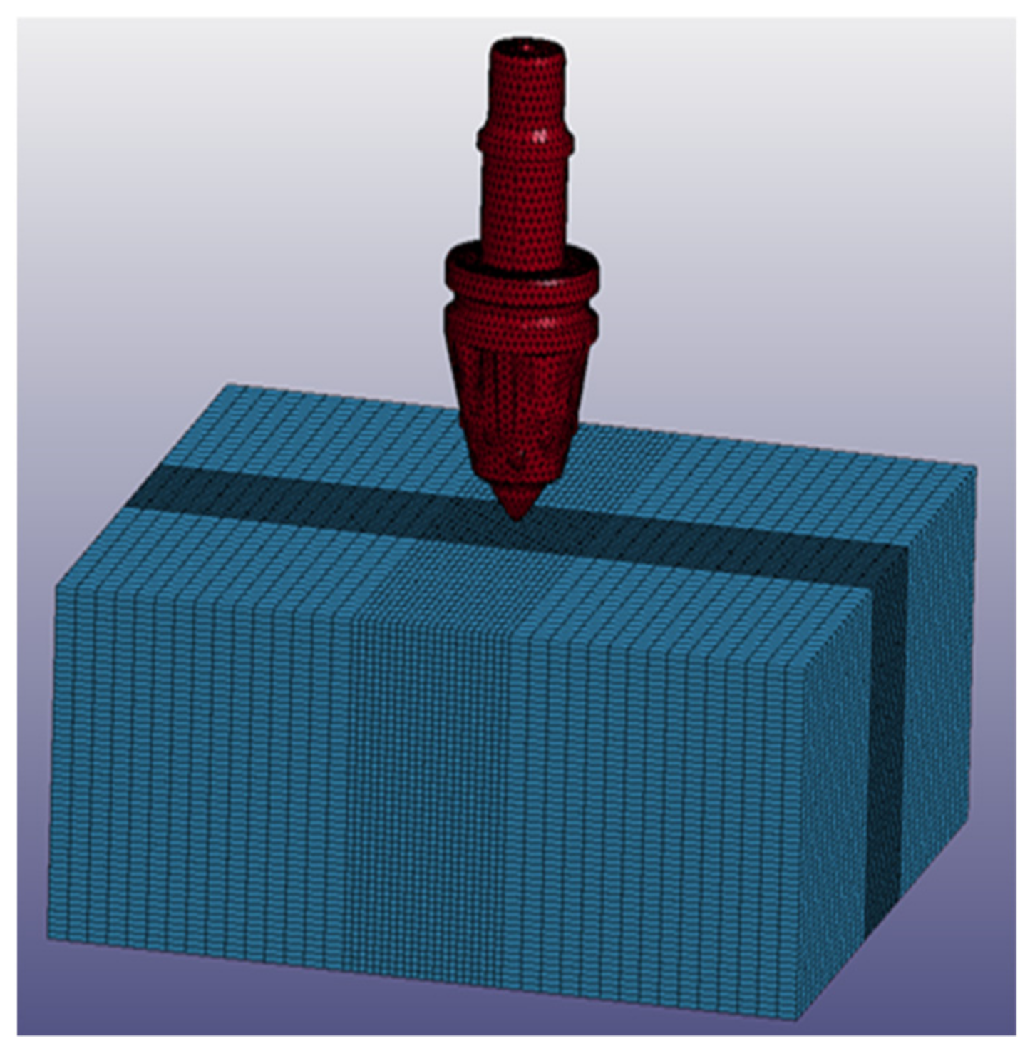
The bit was set to have face to face penetration contact with the rock, i.e., CONTACT_ERODING_SURFACE_ TO_ SURFACE. The full freedom of the bottom and sides of the rock was constrained to limit the radial freedom of the drill bit and to release its axial freedom. Because rock is a semi-infinite body during the drilling process, a BOUNDARY_NON_REFLECTING boundary condition was applied to the bottom and sides of the rock to eliminate the influence of stress reflection on the calculation results. Figure 3 shows a simulation diagram demonstrating dynamic rock-breaking with a drill tooth.
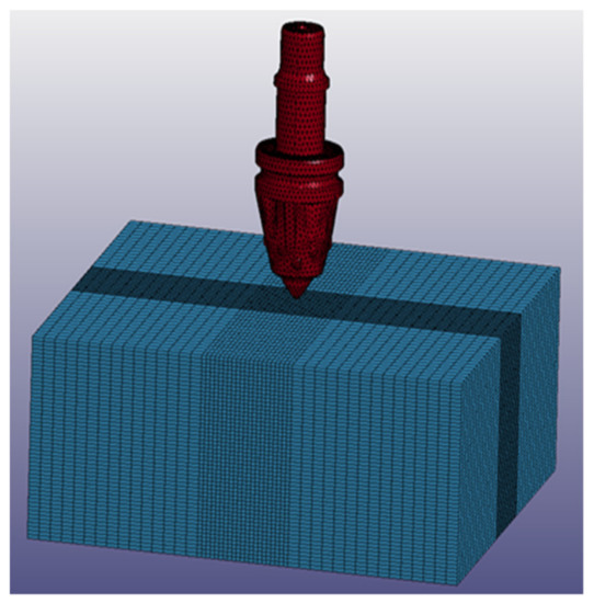
Figure 3.
Drill tooth dynamic rock-breaking simulation diagram.
The quality of the grid division in the simulation process significantly influences the accuracy of the simulation results. If the grid is set to be too dense, then the calculation time will be too long. However, if the grid is set to be too sparse, then the simulation results will deviate from the actual situation greatly. Therefore, the grid in the important area where the bit and rock are in contact with one another is encrypted in this calculation, and the grid selection in other areas is thinned. The drill bit is an irregular model with tetrahedral meshes, whereas the rock is a regular model with hexahedral meshes.
3.2. Simulation Test Scheme
In this simulation, the single-factor test method was adopted. The rotational speed of the spindle was 200, 400, 600, and 800 rad/min, and the drill feed rate was 900, 1800, 2700, and 3600 mm/min. In the simulation, larger feed rates were selected in order to see more obvious rules. Obviously, this feed rate would be too big for actual working conditions. The factors of the simulation experiment are shown in Table 3.

Table 3.
Factors of the simulation experiment.
3.3. Results and Discussion
When the drill bit breaks the rock, the force is very complicated. We can further divide this force into three forces in each direction. They are in the X-, Y-, and Z-directions.
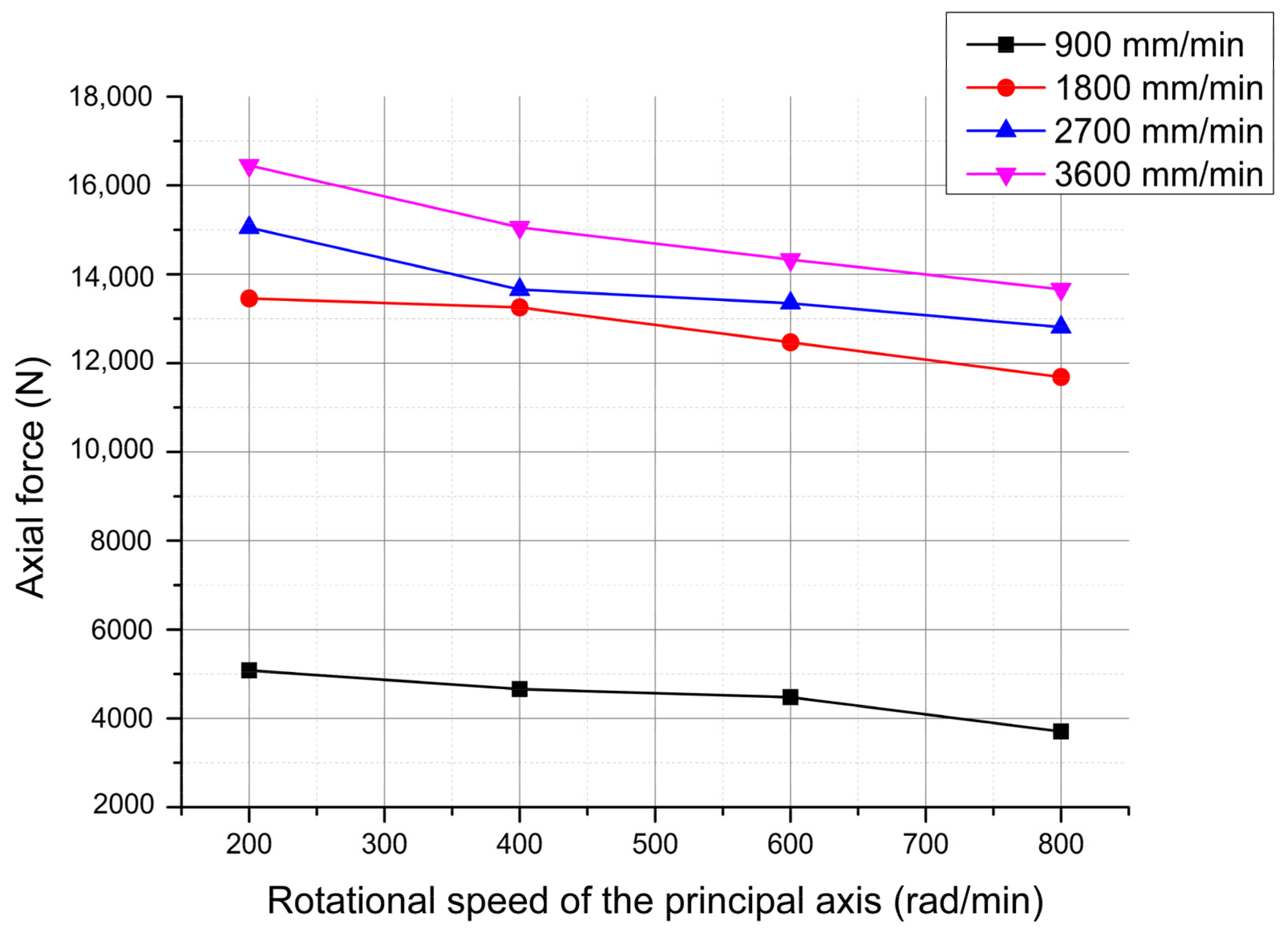
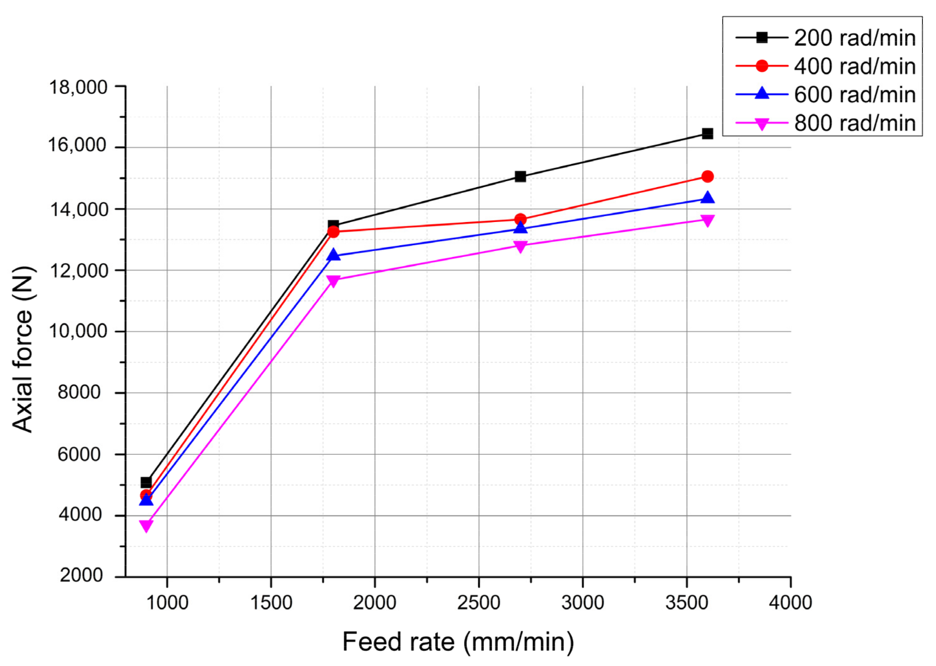
The analysis of the drilling force components in the three directions during the drilling process shows that the drilling force in the X- and Y-directions shows little change in the numerical value. The Z-direction drilling force, i.e., the axial force, can best reflect the changes in the force during the drilling process. Therefore, the simulation results choose the average axial force of the steady state in the drilling process as the measurement index. Figure 4 and Figure 5 show the axial force at a specific time. This specific time refers to the period of time after the pick comes into contact with the rock. This time interval is different for different feed parameters. We chose 1–2 s after the teeth made contact with the rock.

Figure 4.
Average axial force at different rotational speeds.
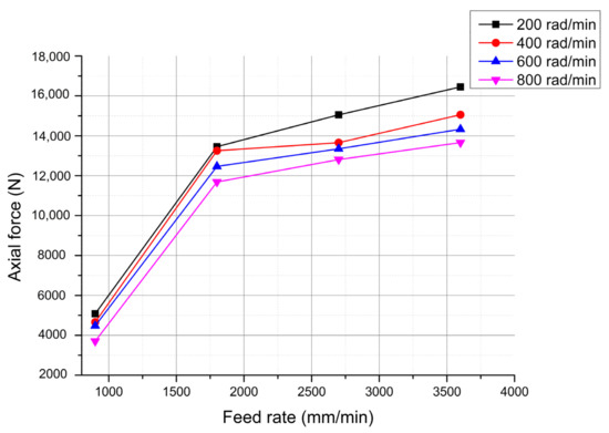
Figure 5.
Magnitude of the average axial force at different feed rates.
3.3.1. Influence of the Rotational Speed on the Axial Drilling Force
Figure 4 shows the influence of the rotational speed on the axial drilling force.
As shown in Figure 4, the abscissa is the rotational speed of the spindle, and the ordinate is the axial force on the bit. When the feed quantity is constant, the axial force decreases as the rotational speed increases. The slope of the curve in Figure 4 is analyzed (Table 4). It can be seen from the results of the slope analysis that the axial force decreases faster as the rotational speed increases.

Table 4.
Slope of the curve in Figure 4.
3.3.2. Effect of the Feed Rate on the Axial Drilling Force
Figure 5 shows the effect of the feed rate on the axial drilling force.
As shown in Figure 5, the abscissa is the feed rate, and the ordinate is the axial force exerted by the bit. As the feed increases, the axial drilling force increases, and the slope of the curve in Figure 5 is analyzed (Table 5). As seen from the results of the slope analysis, as the feed quantity increases, the axial force increases quickly at first and then increases slowly. The increase in feed rate means that the thickness of rock drilled per unit time increases. Therefore, the axial force will also increase. At the same time, this trend is not linear.

Table 5.
Slope of the curve in Figure 5.
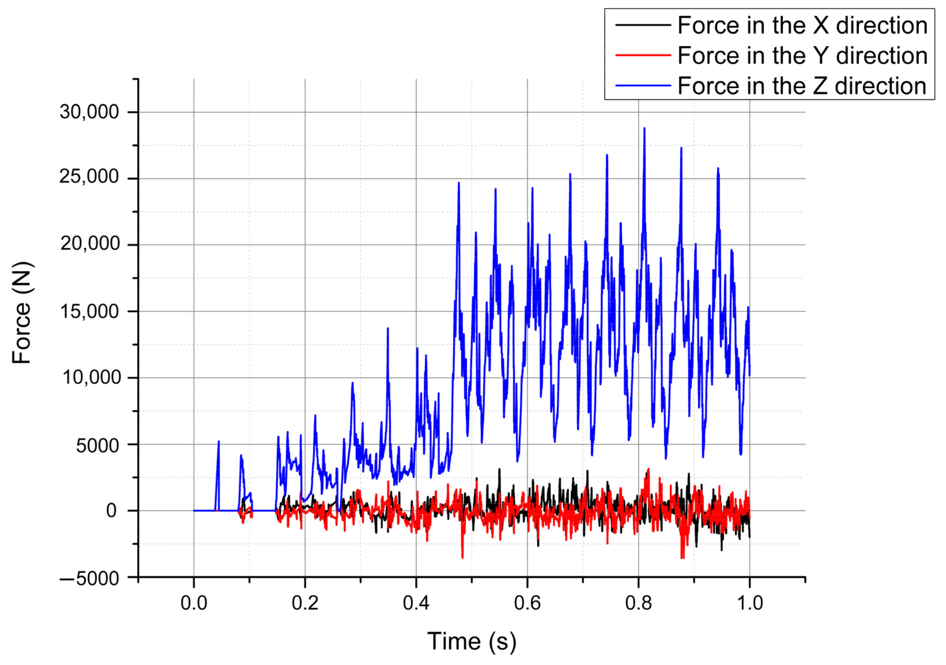
Figure 6 shows the data of the triaxial force on the drill bit at the speed and feed rate of 400 rad/min and 1800 mm/min, respectively. It can be seen that the Z-force changes more obviously than the other two forces. As the time increases, i.e., the increase in the invasion depth, the Z-force increases. Additionally, as the penetration depth increases, the vibration amplitude of the force increases.
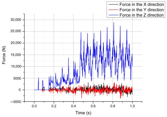
Figure 6.
Three forces applied to the drill bit.
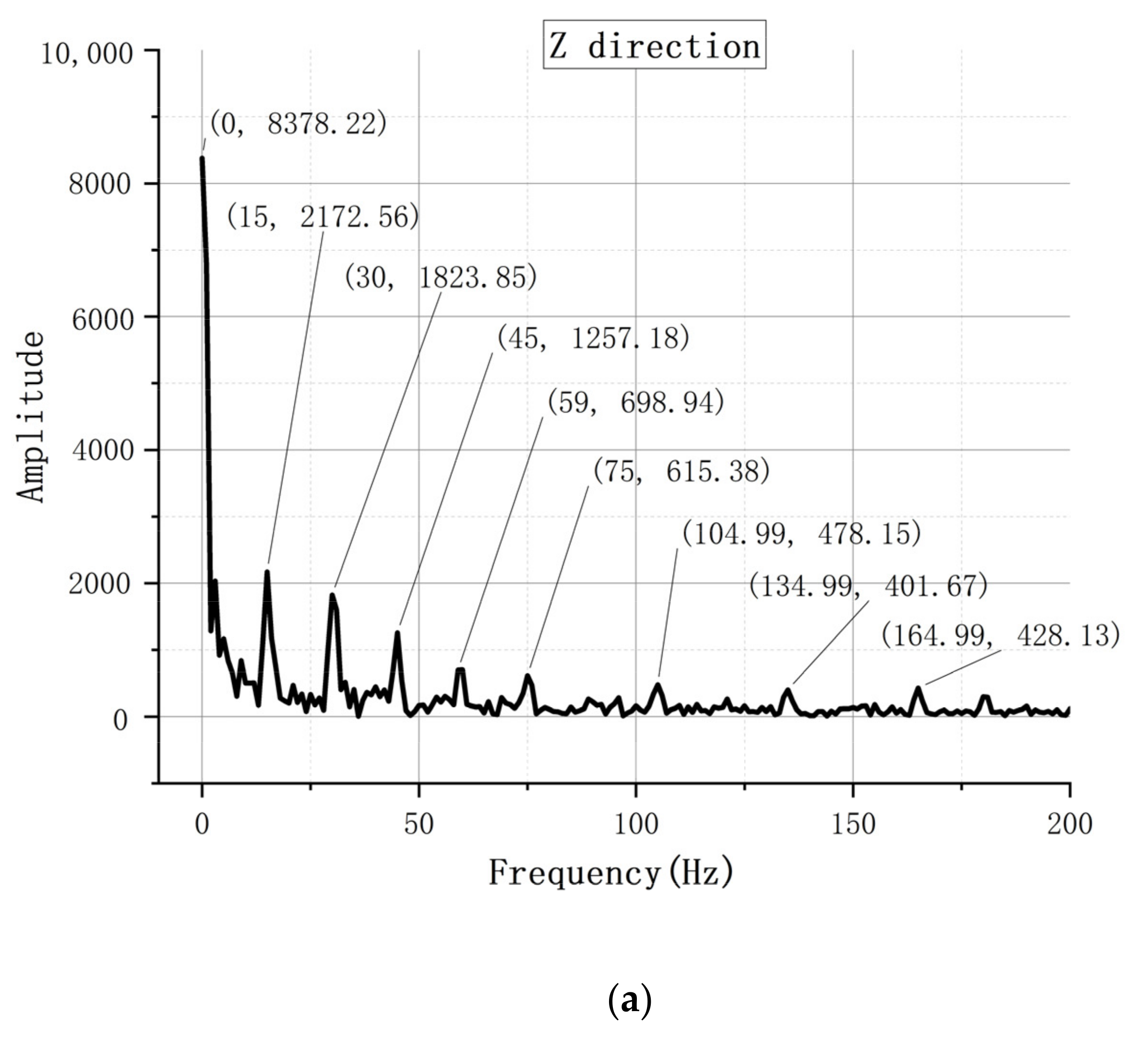
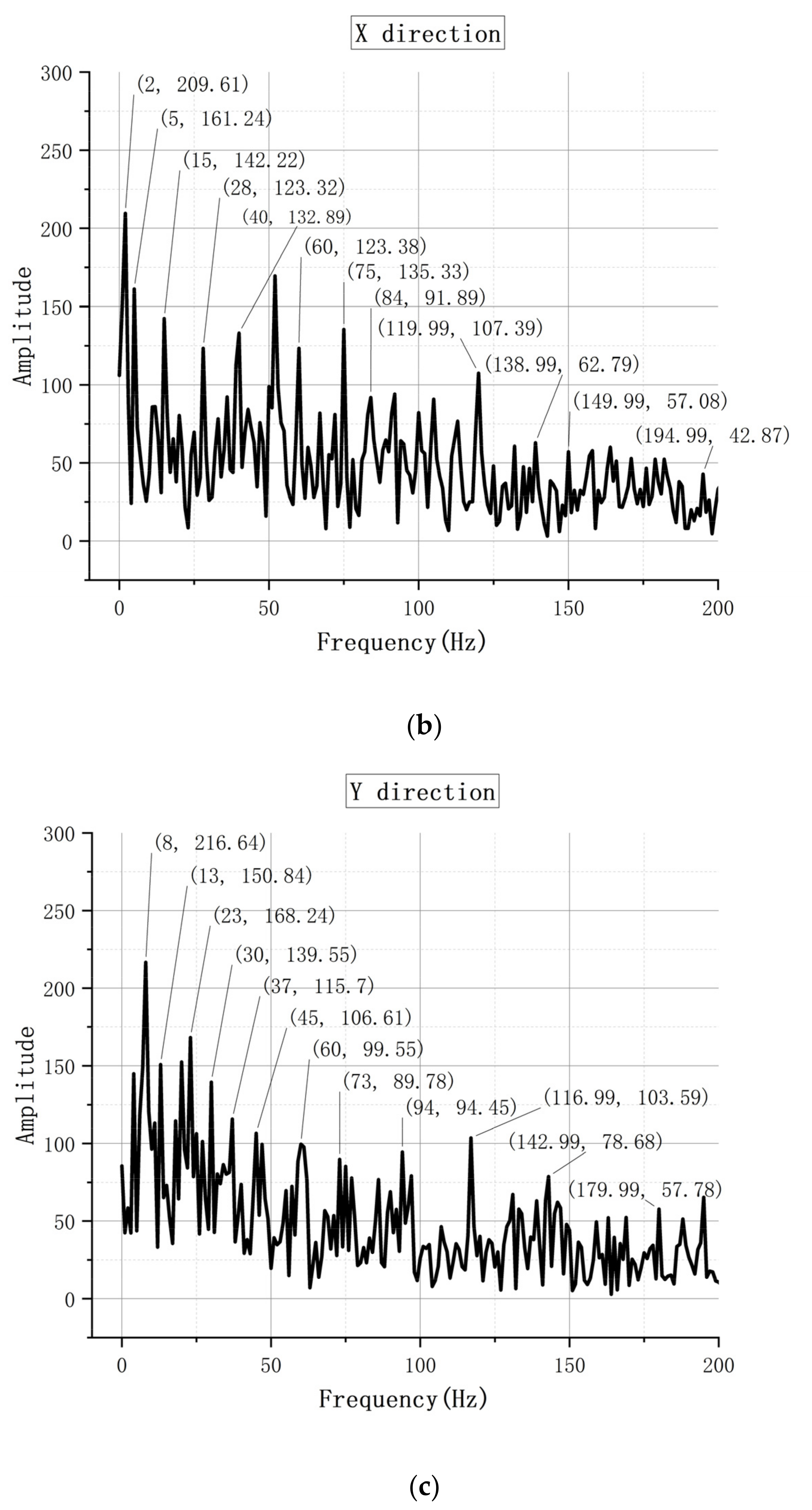
The composition of each signal frequency can be obtained using the fast Fourier transform of the force signals in the three directions. Figure 7 is the frequency analysis result of the force in Figure 6. In terms of the frequency component, the transverse frequency (X and Y) component is more complicated. The vibrational trend is the same at different speeds. The influence of the rotational speed on the axial vibration of the drill bit is less than that of the transverse vibration. The effect of the feed rate on the axial vibration of the drill bit is relatively small.
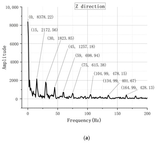
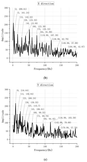
Figure 7.
Results of frequency composition analysis. It is the result of the frequency composition analysis of the three-dimensional force in Figure 6. (a) The frequency composition of the Z-direction force. (b) The frequency composition of the X-direction force. (c) The frequency composition of the Y-direction force.
The analysis results show that, under a certain amount of feed, the vibration in the X- and Y-directions gradually slows down as the rotational speed increases. Conversely, the vibration in the Z-direction gradually intensifies as the rotational speed increases. The rotational speed has a great influence on the vibration in the X- and Y-directions but a relatively small influence on the vibration in the Z-direction. Furthermore, the vibration in the X- and Y-directions gradually slows down as the feed increases. In contrast, the vibration in the Z-direction gradually increases as the feed increases. Compared to the vibrations in the X- and Y-directions, the vibration in the Z-direction is less affected by the amount of feed.
4. Single-Tooth Rock-Breaking Experiment
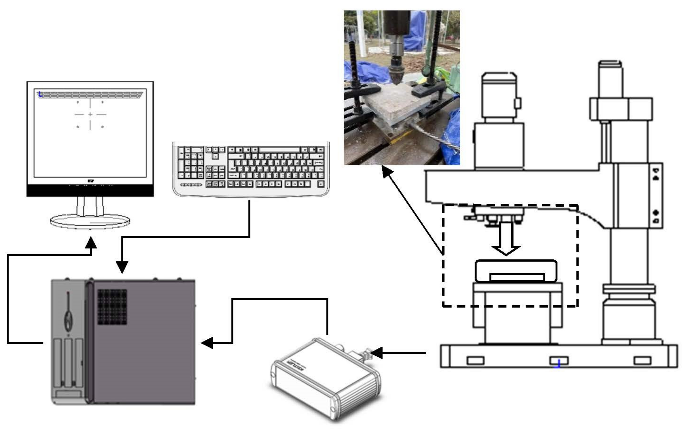
The experimental platform was built based on a Z30 radial drilling machine. Table 6 shows the detailed technical parameters of the drilling machine.

Table 6.
Technical parameters of the Z30 radial drilling machine.
A Kistler 9257B triaxial dynamometer was used in the experiment. It is not easy to measure the force of the drill bit because the drill bit has to rotate and feed while drilling. The dynamometer was placed beneath the rock to measure the forces on the rock in three directions as the drill bit interacts with it [35]. Granite and sandstone were used as the drilling objects, and the Table 7 provides the material parameters of the two rocks. The drill was made of carbide.

Table 7.
Material parameters of the rocks.
Figure 8 shows the test platform.
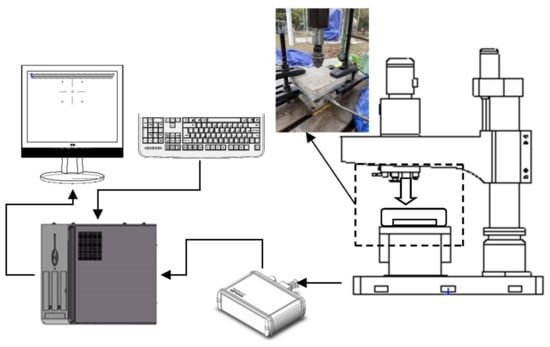
Figure 8.
Schematic of the experimental platform.
A force sensor was placed beneath the rock and picked up the forces applied by the drill bit as it drills through the rock in three directions.
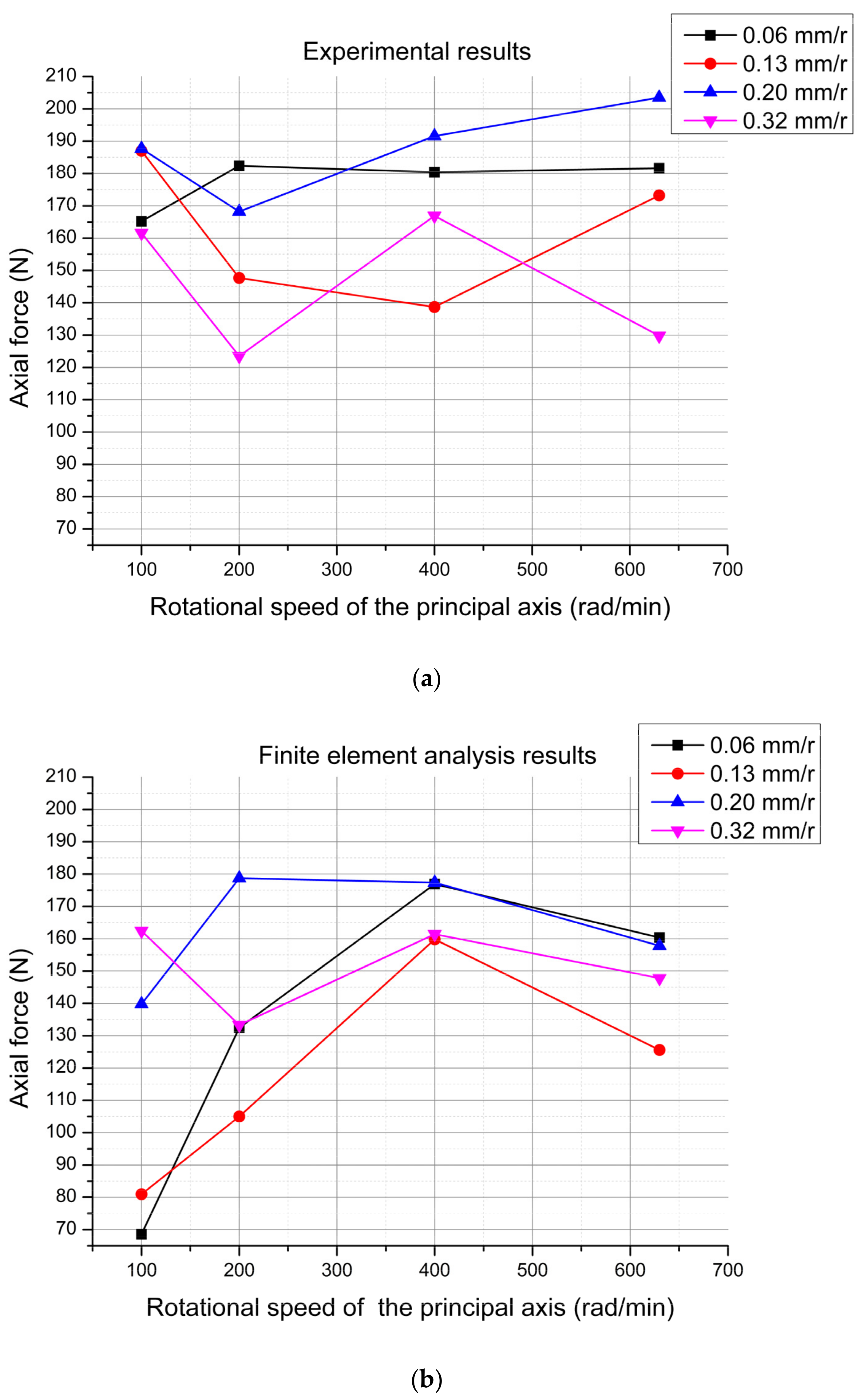
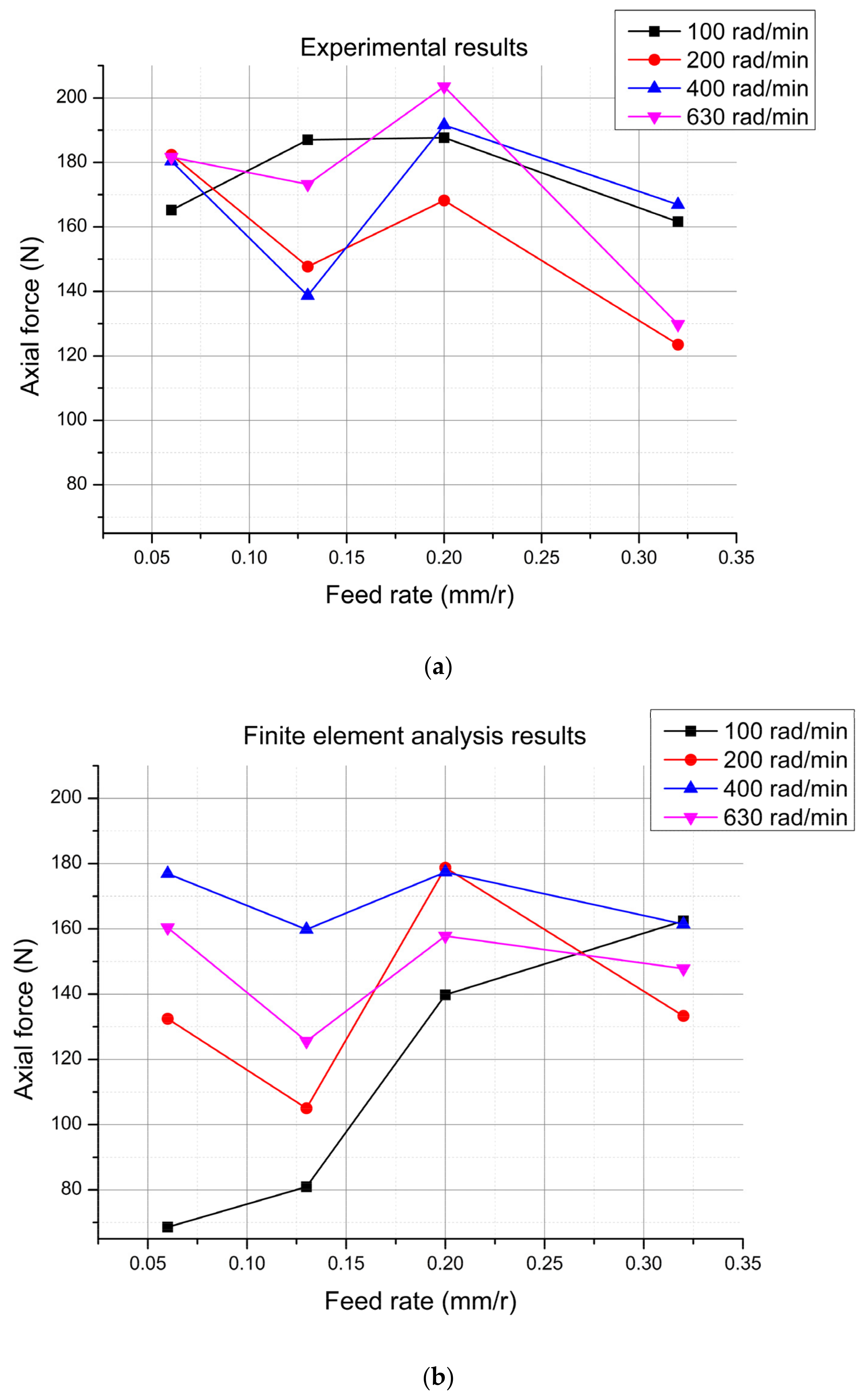
From a security perspective, the experiment selected four rotational speed values: 100, 200, 400, and 630 rad/min. Four feed rates were selected for the experiment: 0.06, 0.13, 0.20, and 0.32 mm/r.
Experiments can only be performed on one rock at a time, so simultaneity cannot be guaranteed. For safety reasons, only a short period of time between the drill bit and rock can be captured for data analysis. The experimental results were studied and analyzed from two dimensions. The two dimensions are the numerical size of the data and the fluctuations in the data. First, the numerical size of the data was analyzed and studied. For comparison, the average value of each piece of test data was taken during the period of time in which the drill bit interacted with the rock. The experimental results show that the forces in the X- and Y-directions do not change much in terms of magnitude. The change in the upward Z force is obvious; thus, more attention was paid to the changes in the upward Z force.
4.1. Analysis from the Numerical Size of Data
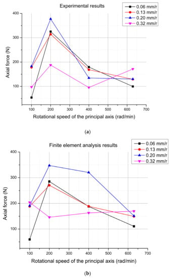
Figure 9.
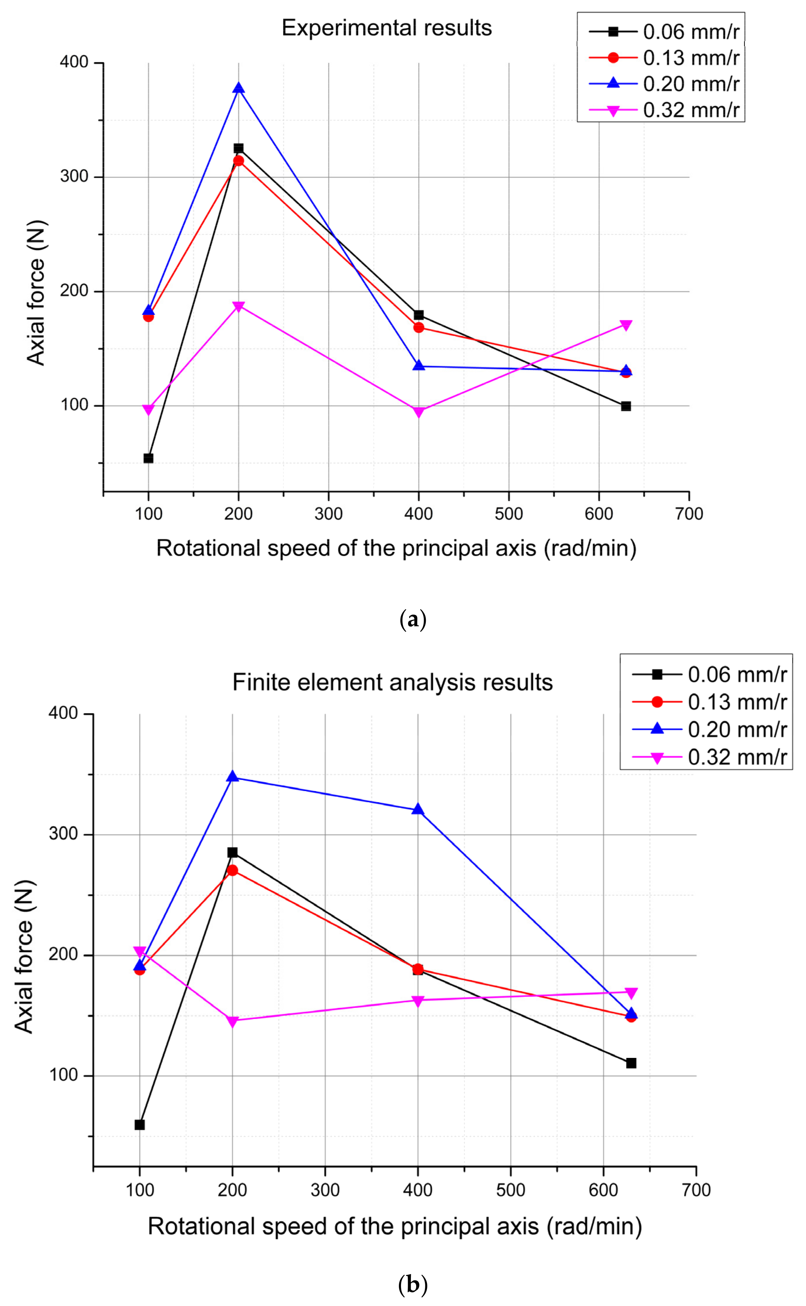
Experimental data 1 for granite. (a) During the test, the axial force changes with the rotational speed under different feed rates. (b) Finite element analysis results corresponding to the test.
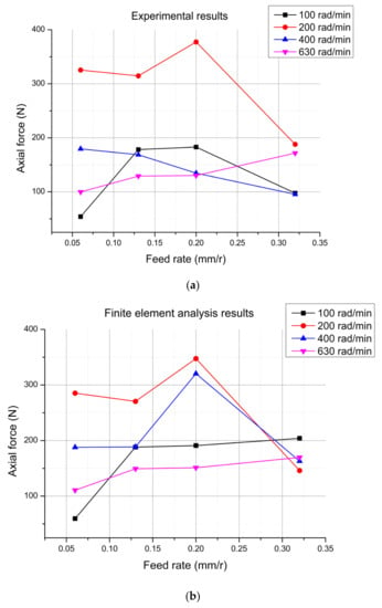
Figure 10.
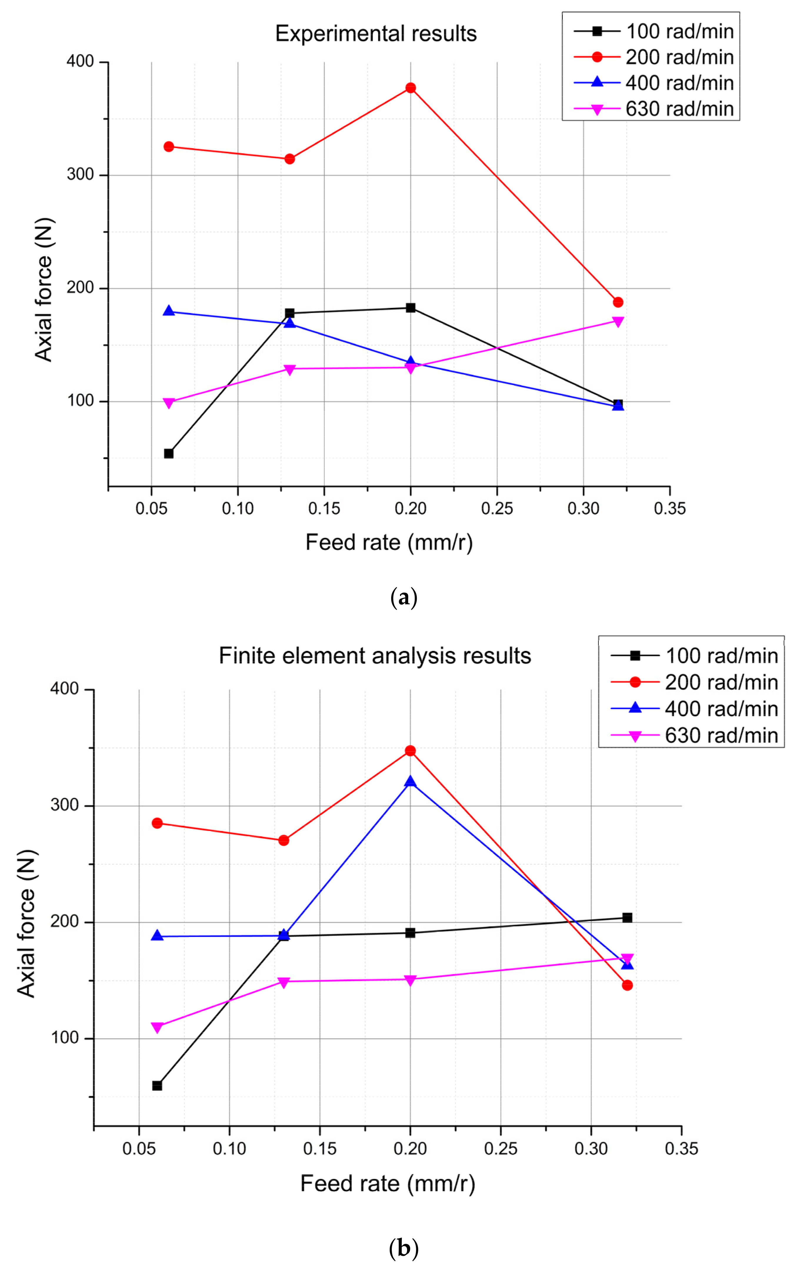
Experimental data 2 for granite. (a) During the test, the axial force changed as the feed rate changed at different rotational speeds. (b) Finite element analysis results corresponding to the test results.
As shown in Figure 9, the abscissa is the rotational speed of the principal axis, and the ordinate is the magnitude of the axial force. It can be seen that, when the feed rates are 0.06 mm/r, 0.13 mm/r, and 0.20 mm/r, the axial force increases first and then decreases as the rotational speed increases. This trend is confirmed by simulation analysis and experimental study.
As shown in Figure 10, the abscissa is the amount of feed, and the ordinate is the magnitude of the axial force. At constant speeds, the axial force increases as the feed increases, which is consistent with the simulation study on the whole.
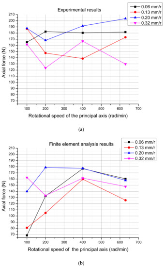
Figure 11.
Experimental data 1 for sandstone. (a) During the test, the axial force changed with the rotational speed under different feed rates. (b) Finite element analysis results corresponding to the test results.
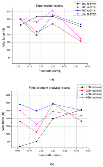
Figure 12.
Experimental data 2 for sandstone. (a) During the testing process, the axial force changed with the change in feed rate at different rotational speeds. (b) Finite element analysis results corresponding to the test results.
As shown in Figure 11, the abscissa is the rotational speed of the principal axis, and the ordinate is the Z force, i.e., the magnitude of the axial force. As the rotational speed increases, no obvious regular changes can be observed in the axial force. By comparing the experimental research and the simulation analysis, the following conclusions can be drawn: when the feed rate is 0.06 mm/r and 0.32 mm/r, the results of the simulation analysis are consistent with those of experimental research. When the feed rates are 0.13 mm/r and 0.20 mm/r, the trend of the simulation analysis is inconsistent with that of experimental research.
As shown in Figure 12, the abscissa is the feed and the ordinate is the magnitude of the axial force. At constant speeds, the axial force fluctuates greatly as the feed increases, showing no obvious rule changes. However, finite element analysis shows certain rules. This is consistent with the results of the third part of this study.
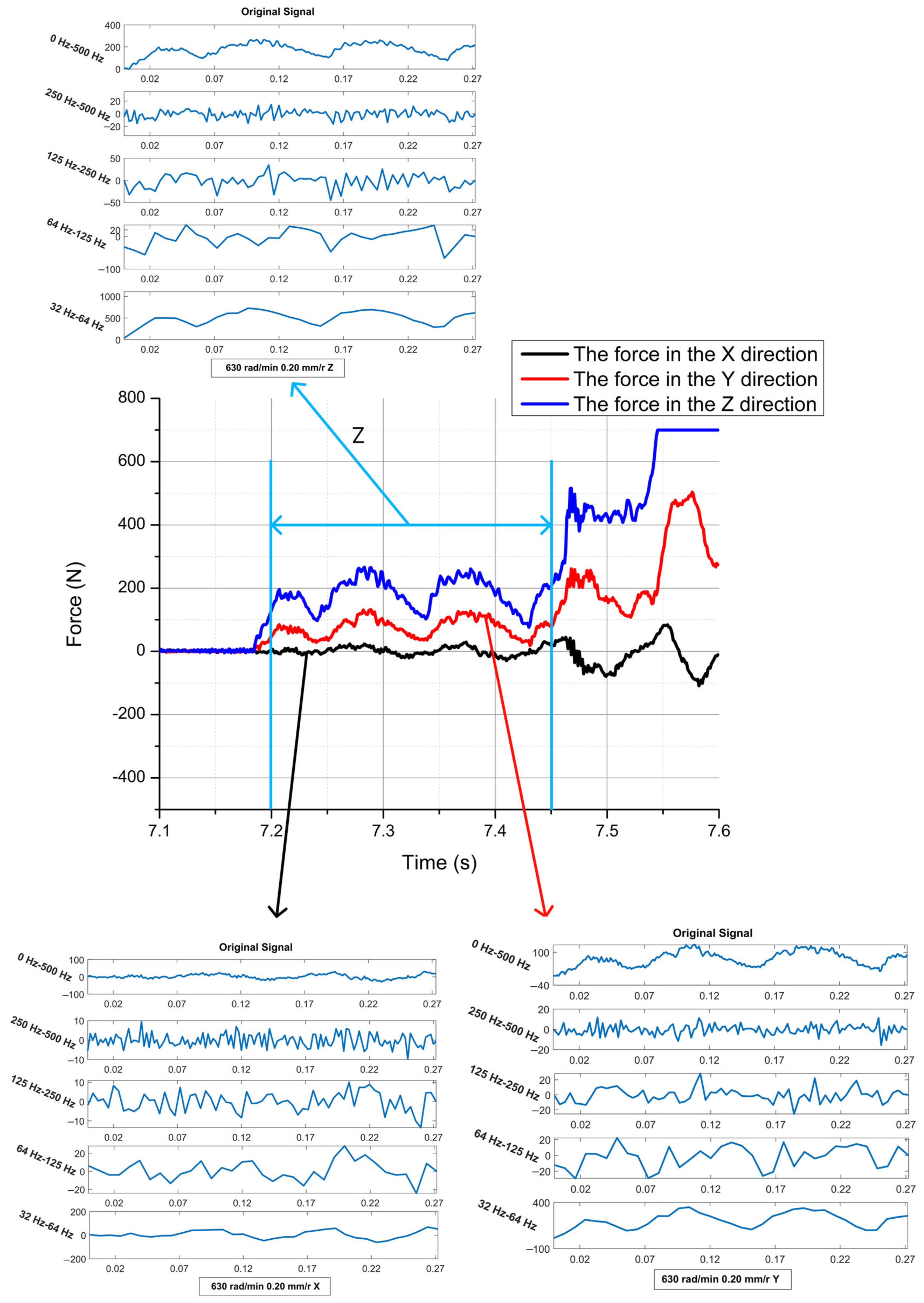
Figure 13 shows the experimental data when the speed is 630 rad/min and the feed rate is 0.20 mm/r.
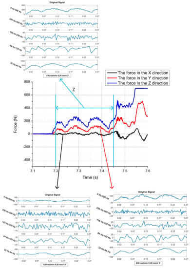
Figure 13.
Forces in three directions at a rotational speed of 630 rad/min and feed rate of 0.20 mm/r.
The leaping intrusion rule during the rock-breaking process is verified based on the analysis of each experimental result. At the same time, the effect of unloading is bigger than that of loading in the mechanical rock-breaking process. During drilling, the bit tooth is briefly separated from the rock mass; thus, there is a sudden downward trend in the force.
The axial force increases as the penetration depth increases. At the local depth, the axial force suddenly decreases and then increases, and the depth interval gradually decreases at the points. The above phenomenon shows that the rock is suddenly broken due to the initial crack in the rock invasion process, leading to the jump invasion of the tooth. When the axial force increases, the crack propagation accelerates and the tangential force fluctuates with displacement. Rock stripping is the main tensile failure; the rock is cut by tangential force, resulting in a large rock stripping phenomenon. At this stage, when the tangential force reaches a certain critical value, the tooth suddenly leaps forward, the rock block breaks off, and the tangential force decreases rapidly. As the pick continues to make contact with the new rock face, there is a sudden increase in the tangential force.
The greater the rock strength, the more difficult it is for cracks to occur in the rock mass crack and for those cracks to expand when the pick is invaded. The rock strength can also be verified through field experiments, determining that sandstone cracks are easy to produce and break quickly.
4.2. Analysis from the Vibration Aspect
During pile hole excavation, axial drilling tool vibration may occur due to the contact between the drill teeth and the bottom of the hole and the unstable axial reaction force of the drill bit. If the frequency of the excitation source is close to a certain natural frequency of the drill pipe, then the drill pipe will form a resonance, causing the drill bit to separate from the bottom of the hole and, at the same time, bounce at the bottom of the hole. When this happens, the huge impact load will accelerate the fatigue speed of the drill tool and reduce the life of the drill bit.
There are many non-stationary signals in the drilling process, and there is large variation in its running state. By studying these non-stationary signals, we can further understand the mechanism through which bit teeth break through rocks. Wavelet analysis has combined the abilities of the frequency domain and time domain analyses and can accurately analyze non-stationary signals.
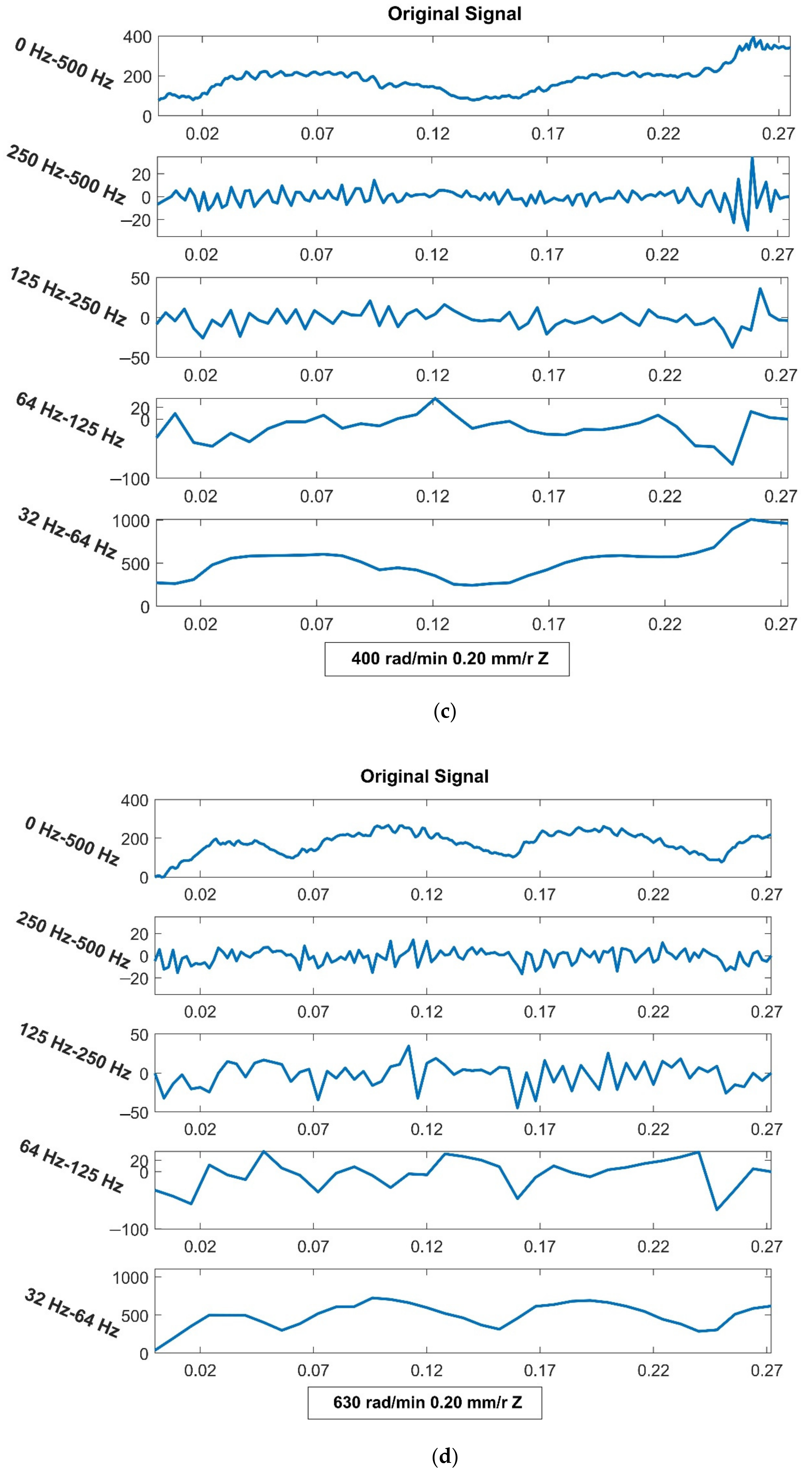
The experimental data were decomposed into a three-layer wavelet with a DB1 wavelet. The 0–500 Hz signals were extracted from the original signal; however, no obvious differences were observed in this interval. Therefore, the signal was divided into four phases: 32–64 Hz, 64–125 Hz, 125–250 Hz, and 250–500 Hz.
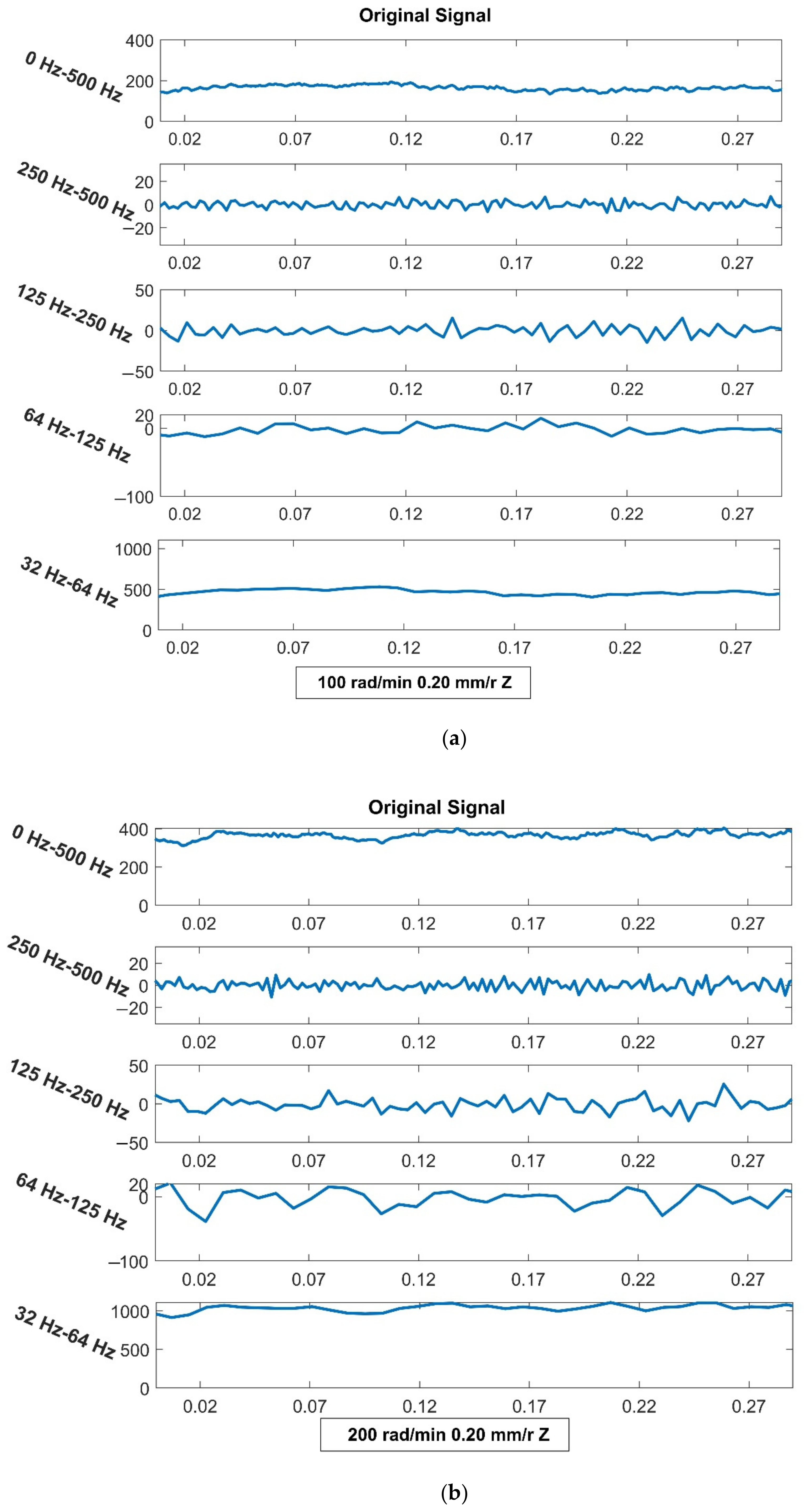
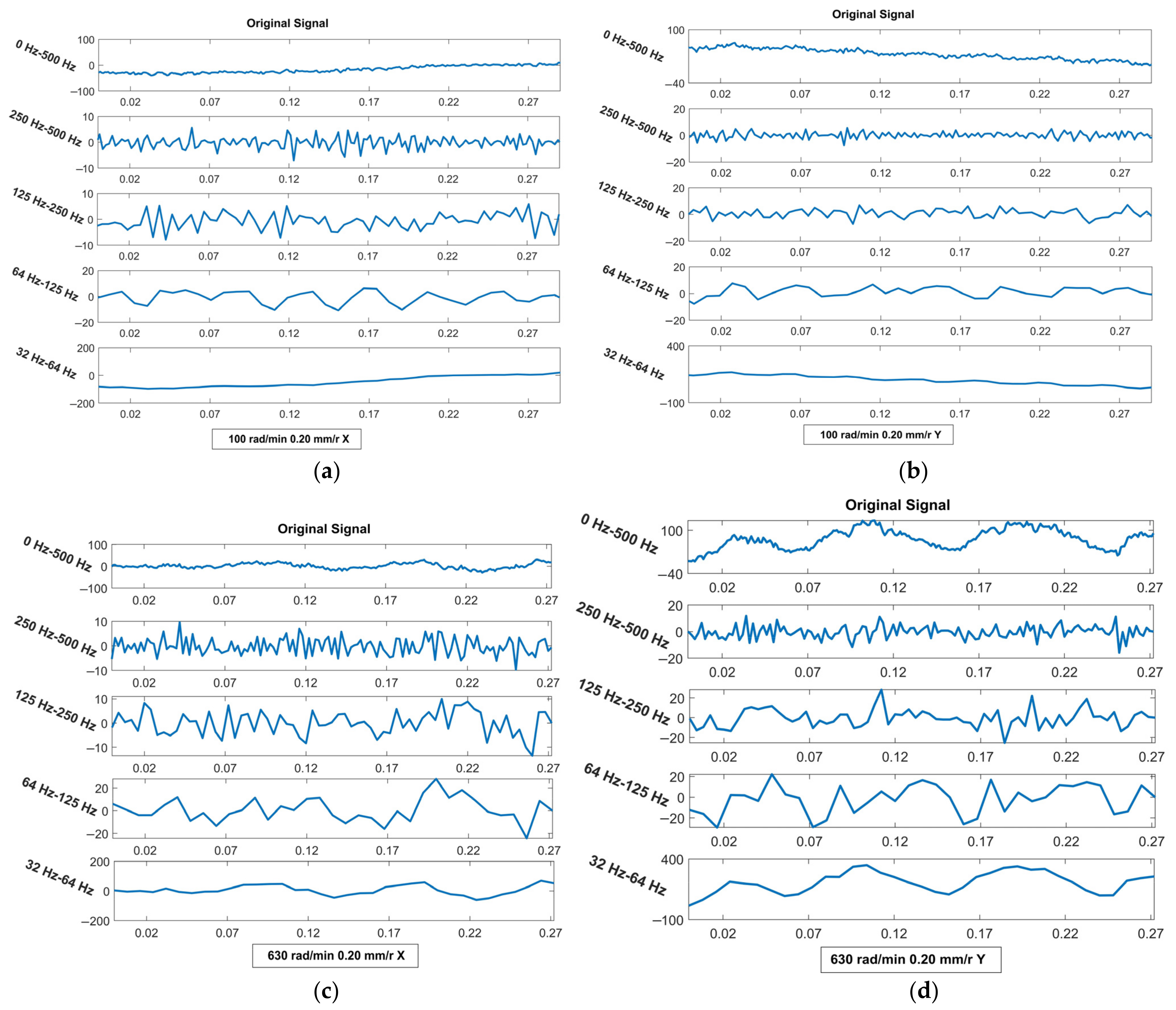
We conducted a wavelet analysis on the data for the three directions and discussed the influence of speed and feed on the vibrations from three directions. Figure 14 shows the results of the wavelet analyses in the Z-direction when the feed rate is 0.20 mm/r.
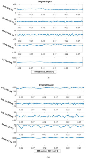
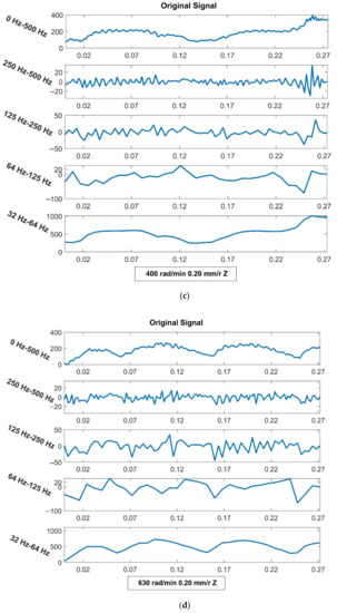
Figure 14.
Results of wavelet analysis in the Z-direction when the feed rate is 0.20 mm/r and the rotational speed is different. (a) The rotational speed is 100 rad/min. (b) The rotational speed is 200 rad/min. (c) The rotational speed is 400 rad/min. (d) The rotational speed is 630 rad/min.
It can be seen from the results that the low-frequency (32 Hz–64 Hz) signal is the most important part of the original signal. As the speed increases (the speed is 100, 200, 400, 630 rad/min), the vibration of each frequency band is strengthened. When the rotational speed is constant, the vibration slows down as the feed increases. The vibrations tend to be stable and more regular.
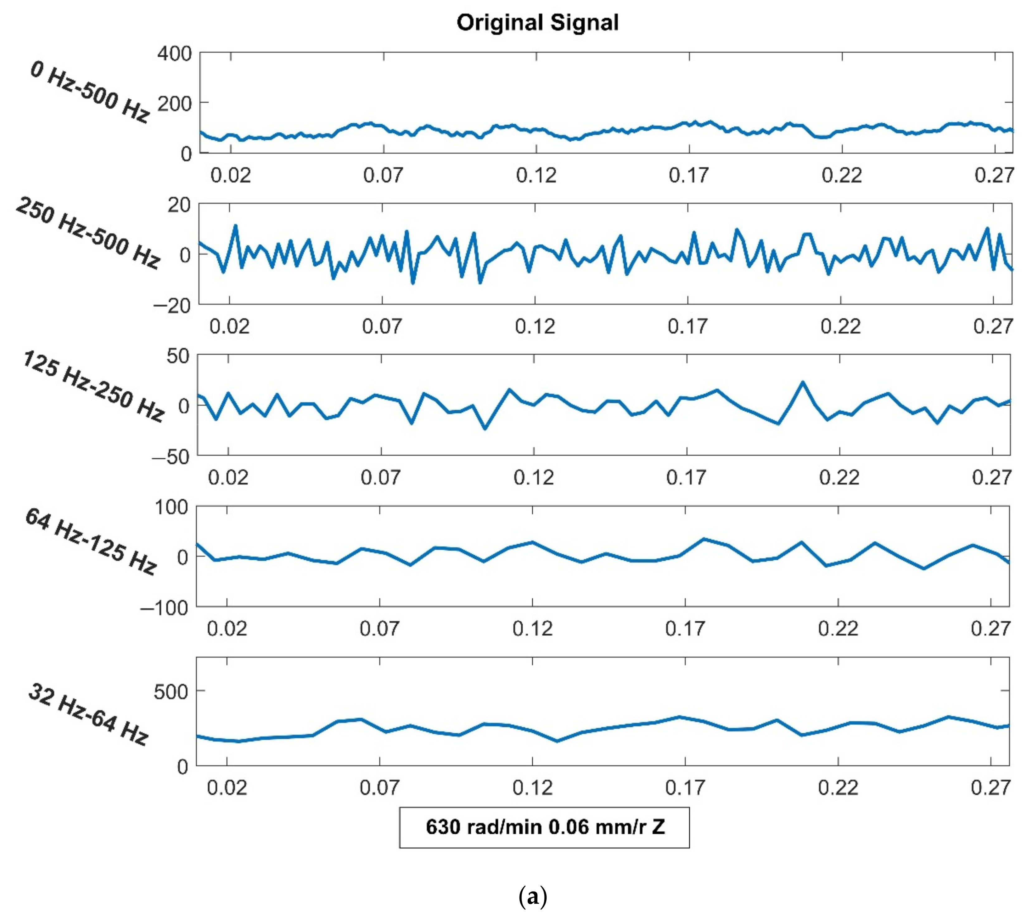
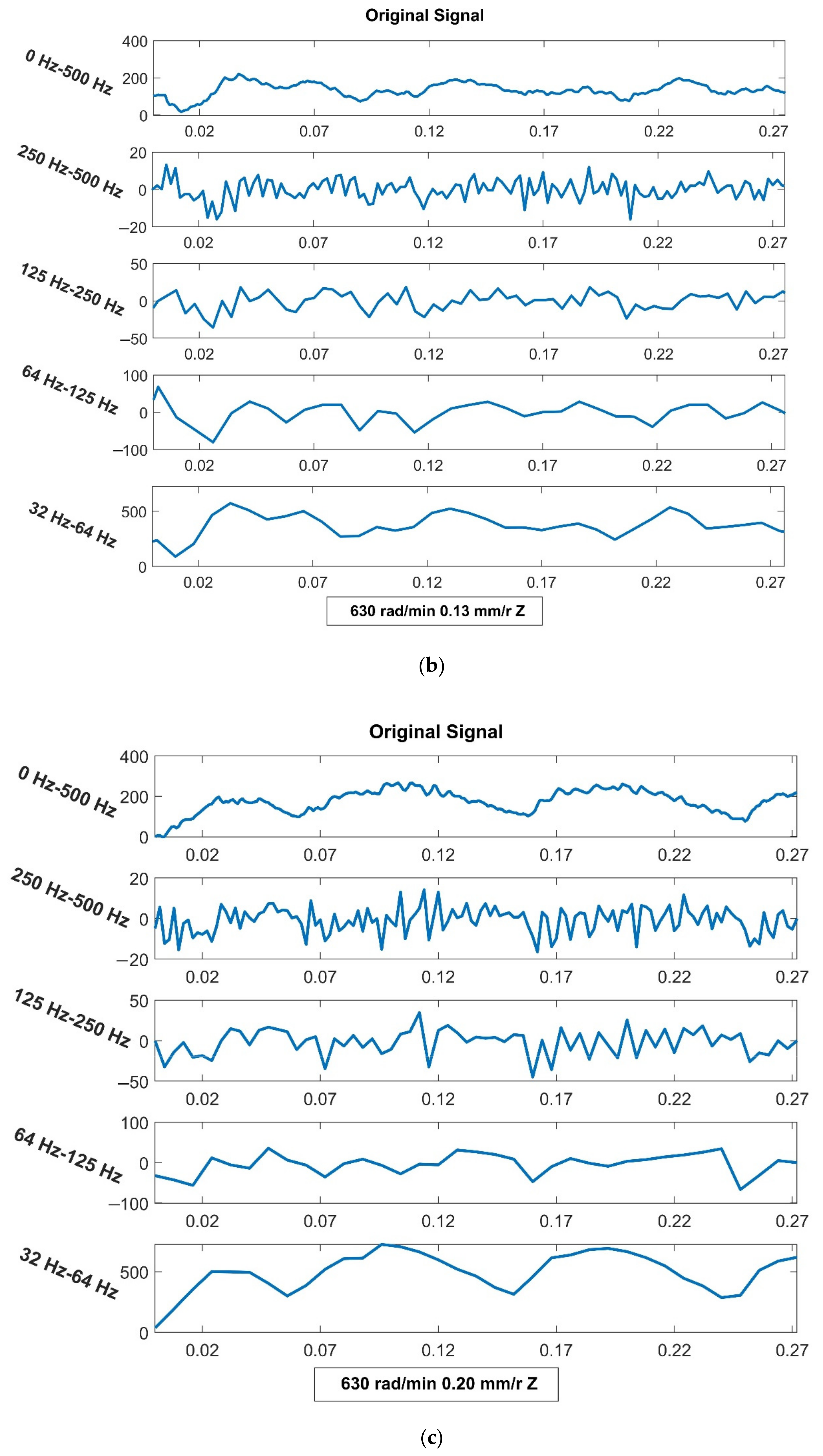
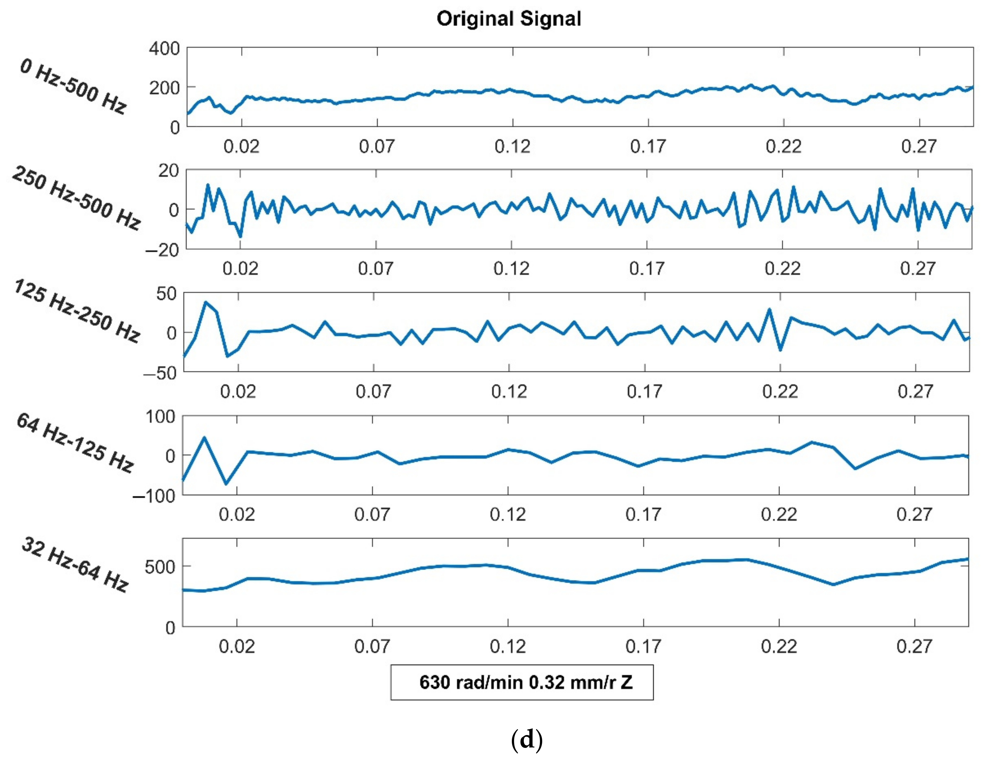
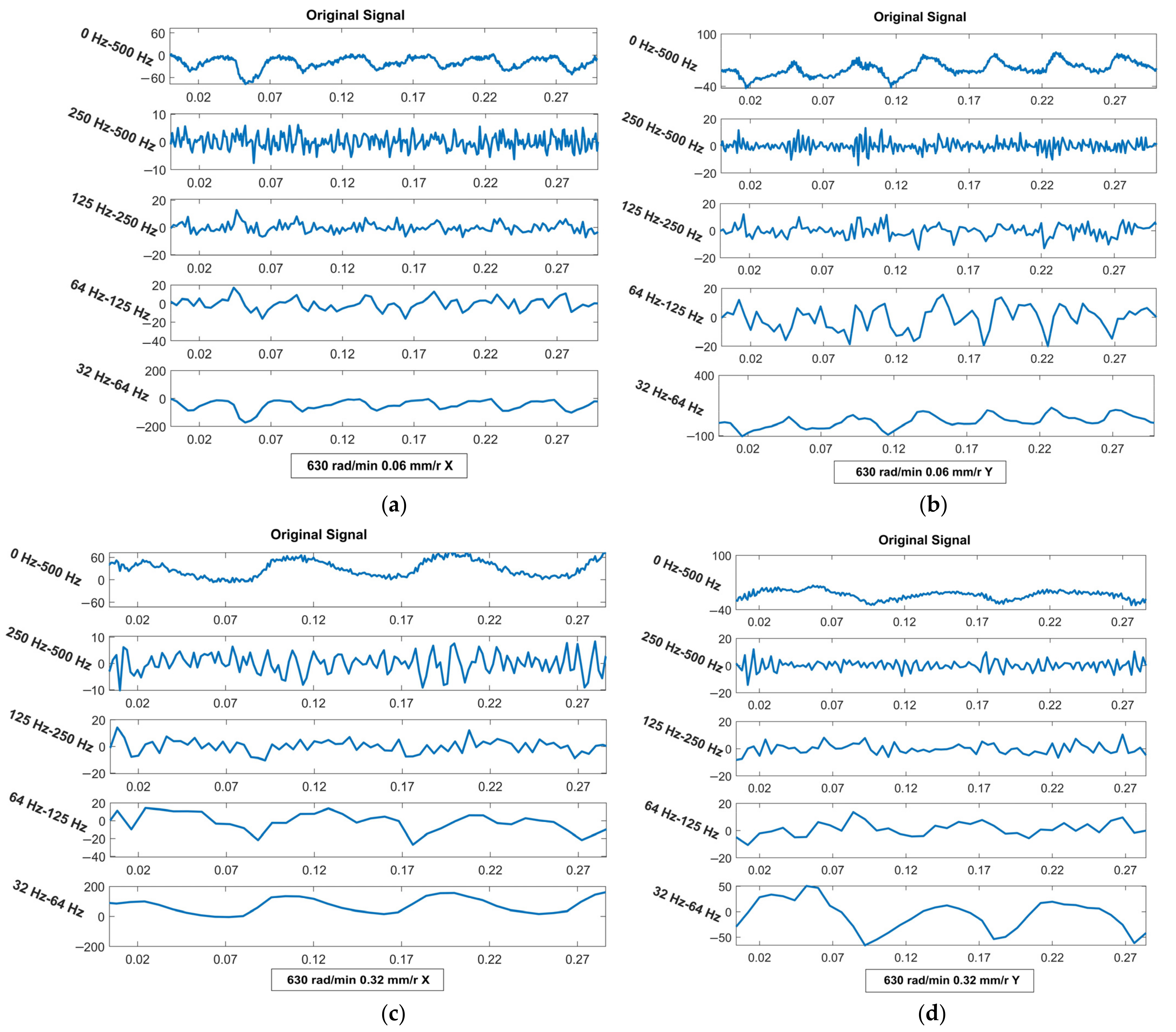
Figure 15 shows the results of the wavelet analyses in the Z-direction when the rotational speed of the principal axis is 630 rad/min.
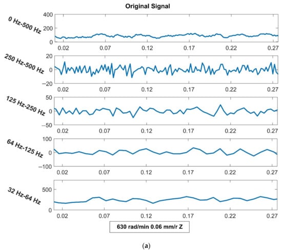
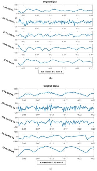
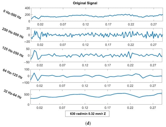
Figure 15.
Results of wavelet analysis in the Z-direction when the feed rate is different and the rotational speed is constant. (a) The feed rate is 0.06 mm/r. (b) The feed rate is 0.13 mm/r. (c) The feed rate is 0.20 mm/r. (d) The feed rate is 0.32 mm/r.
At different speeds, the vibrational trend is the same. The influence of the rotational speed on the axial vibration of the drill bit is less than that on transverse vibration.
Figure 16 shows the results of the wavelet analyses in the X- and Y-directions. In the transverse direction, the vibration trend in the bit along the X and Y axes is the same and no great differences are observed. When the bit pressure is constant and in a certain speed range, the drilling speed is slow and the transverse vibration is severe at low speeds. The transverse vibration of the bit decreases as the rotational speed increases due to the following reasons. When drilling at low speeds, the drilling force of the bit cutter is insufficient and the bit cannot break the rock effectively, resulting in stumbling while the bit is drilling. The rock has a reverse impact on the bit, aggravating the transverse vibration of the entire drilling tool (including the drill pipe). As the rotational speed increases, the cutting force of the drill bit increases and the transverse vibration of the drill part slows down.
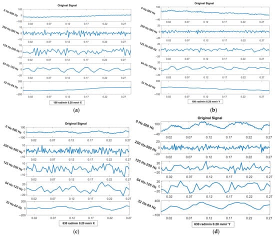
Figure 16.
Results of wavelet analysis in the X- and Y-directions when the rotational speed is different and the feed rate is constant (0.20 mm/r). (a) Results of wavelet analysis in the X-direction when the rotational speed is 100 rad/min. (b) Results of wavelet analysis in the Y-direction when the rotational speed is 100 rad/min. (c) Results of wavelet analysis in the X-direction when the rotational speed is 630 rad/min. (d) Results of wavelet analysis in the X-direction when the rotational speed is 630 rad/min.
From the axial perspective, the vibrational trend is the same under different rotational speeds. As the rotational speed increases, the axial vibration intensifies. Meanwhile, the top teeth of the bit are in frequent contact with the rock as the rotational speed increases, increasing the axial reaction force on the bit. The axial vibration is aggravated by the discontinuous axial impact.
The effect of the feed rate on the axial vibration of the drill bit is relatively small. Figure 17 shows the transverse analysis results of different feed rates at a rotational speed of 630 rad/min. From the transverse view, the transverse vibration of the drill part gradually decreases as the feed increases. The reason for this is that, when the feed is small, the drill bit cannot effectively drill into the rock and soil layer and may even produce a slipping phenomenon. The frequent collision between the drill bit and hole wall will produce a large reverse impact on the drill bit, resulting in the drill pipe experiencing a large transverse vibration. As the feed rate increases, the ability of the drill bit to enter the rock and soil improves significantly. Additionally, the rock and soil that are completely wrapped around the drill bit have a certain ability to absorb the vibration of the drill bit to reduce the transverse vibration transmitted to the drill pipe.
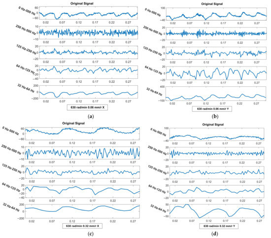
Figure 17.
Results of wavelet analysis in the X- and Y-directions when the feed rate is different and the rotational speed is constant. (a) Results of wavelet analysis in the X-direction when the feed rate is 0.06 mm/r. (b) Results of wavelet analysis in the Y-direction when the feed rate is 0.06 mm/r. (c) Results of wavelet analysis in the X-direction when the feed rate is 0.32 mm/r. (d) Results of wavelet analysis in the Y-direction when the feed rate is 0.32 mm/r.
From the axial perspective, the axial vibration of the drill increases gradually as the feed increases. The axial vibration is mainly caused by the imbalance between the pressure on the drill bit and the axial reaction of the rock and soil. The intermittent drilling of the bit picks causes the axial reaction force of the bit to change discontinuously and randomly. This causes the force of the drill pipe along the axial direction to be unbalanced, causing axial vibration in the bit. The larger the feed, the greater pressure on the bit and the more difficult it is to balance the force, resulting in the bit having a greater axial vibration.
The vibration when drilling granite is stronger than that when drilling sandstone [36]. Some studies show that the vibrational displacement range of rock increases as the rock stiffness increases. This mechanism has been verified in a field experiment. Through the field experiment, it is known that, as the speed and feed increase, the vibration of the drilling machine is stronger.
The vertical vibration is aggravated by hard grinding lithology in the tight stratum and will demonstrate poor drilling ability.
The less dense the rock, the more likely it is to vibrate. The less dense rock starts out vibrating at a higher rate, and the vibration rate decreases as the drilling continues. A denser rock will vibrate at a lower speed first, and the speed of the vibration will then increase.
The elastic modulus is the stress required by the elastic deformation unit of a material under the action of external force, reflecting the material resistance index to deformation. Stiffness K is the ability of a structure or member to resist elastic deformation and is expressed in terms of the force or torque required to produce unit strain. The former is the property of the material component, whereas the latter is a solid property of the material. They are positively correlated. Rock with a large elastic modulus and high rigidity is not easily deformed.
The smaller the stiffness of the rock, the larger the vibrational amplitude under the impact action and the easier it is to reach the maximum vibrational displacement and velocity [37]. The greater the stiffness of the rock, the stronger the rock’s ability to resist deformation, the less prone the rock is to deformation, and the smaller the maximum vibrational displacement [38].
5. Conclusions
The axial reaction force of the rock on the drill bit presents a certain law according to different rock types and drilling process parameters. When the feed is constant, the axial reaction force of the drill bit decreases as the rotational speed increases. However, when the rotational speed is constant, the axial reaction force of the bit increases as the feed increases. From the vibration viewpoint, when the feed amount is constant, the transverse vibration slows down and the axial vibration intensifies as the rotational speed increases. When the rotational speed is constant, as the feed increases, the transverse vibration slows down and the axial vibration intensifies. The two factors, feed and speed, have a greater influence on the transverse vibration.
The experimental results show that the axial reaction test results of granite are consistent with the simulation results, while the experimental data for sandstone have no obvious relationship. The wavelet analysis of all the test data verifies the rules of vibration obtained by the simulation. The vibrational trend is the same at different speeds. The influence of the rotational speed on the axial vibration of the drill bit is less than that on the transverse vibration. The effect of the feed rate on the axial vibration of the drill bit is relatively small. The vibration of drilling granite is stronger than that of drilling sandstone.
When the drilling rig is running, a fault or the unstable vibration often appears in the drilling tool, thereby significantly affecting the stationarity of the dynamic signal. It can be said that the non-stationary performance reflects the failure of the drilling tool to a certain extent. Through the research on the vibration mechanism and related theories of drilling tools, the unstable vibration of drilling tools can be changed by reasonably adjusting the rotational speed and bit pressure. Thus, the service time of drilling tools can be prolonged. At the same time, the related research of formation lithology identification can also be carried out with the help of wavelet transform.
Author Contributions
Conceptualization, H.L. and J.W.; methodology, K.H.; software, Q.M.; validation, H.L., Q.M. and Q.L.; formal analysis, J.D.; investigation, J.D.; resources, J.W.; data curation, H.L.; writing—original draft preparation, J.W.; writing—review and editing, H.L.; visualization, K.H.; supervision, K.H.; project administration, Q.L.; funding acquisition, J.W. All authors have read and agreed to the published version of the manuscript.
Funding
This research was financially supported by strategic cooperation between Yibin City and Sichuan University (2019CDYB-6).
Institutional Review Board Statement
Not applicable.
Informed Consent Statement
Not applicable.
Data Availability Statement
Not applicable.
Conflicts of Interest
The authors declare no competing financial interest.
References
- Li, D.; Cai, M.; Masoumi, H. A constitutive model for modified cable bolts exhibiting cone shaped failure mode. Int. J. Rock Mech. Min. Sci. 2021, 145, 104855. [Google Scholar] [CrossRef]
- Detournay, E.; Richard, T.; Shepherd, M. Drilling response of drag bits: Theory and experiment. Int. J. Rock Mech. Min. Sci. 2008, 45, 1347–1360. [Google Scholar] [CrossRef]
- Panayirci, H.M. An experimental study on steering response of PDC drill bits. J. Pet. Sci. Eng. 2022, 208, 109440. [Google Scholar] [CrossRef]
- Huang, K.; Yang, Y.; Li, G.; Wang, Y.; Ren, H.; Niu, S. Torsion and vibration reduction mechanism of roller PDC hybrid bit. J. Pet. Sci. Eng. 2022, 208, 109491. [Google Scholar] [CrossRef]
- He, Z.; Shi, L.; Li, L.; Kong, L.; Zhang, X.; Liu, X. Study on the Mechanism of Stick-Slip Vibration Based on Single-Cutter Rock Breaking Finite Element Simulation. China Pet. Mach. 2021, 49, 17–26. [Google Scholar]
- Liu, B.; Ni, P.; Tan, X.; Zhang, C. Research on rock breaking efficiency of rotary punching drilling rig. J. Mech. Electr. Eng. 2020, 37, 801–805. [Google Scholar]
- Liu, B.; Wu, J.; Zhang, J.; Shi, X.; Li, S. Numerical Simulation on the Rock Breaking of Cutter Teeth of PDC Cutter Based on Discrete Element Method. Min. R & D 2021, 41, 165–169. [Google Scholar] [CrossRef]
- Liu, S.; Ni, H.; Wang, Y.; Zhang, H. Mechanism of multi-dimensional impact loads applied in increasing the rock cutting efficiency of a PDC bit. J. Vib. Shock. 2021, 40, 258–264. [Google Scholar]
- Lu, Z.; Zheng, J.; Jiang, Z.; Zhao, F. An Experimental Study on Rock Breaking Efficiency with Ultrasonic High-Frequency Rotary-Percussive Drilling Technology. Pet. Drill. Tech. 2021, 49, 20–25. [Google Scholar] [CrossRef]
- Zhu, X.; He, L.; Liu, W.; Luo, Y.; Yang, F. Research on particle jet and its auxiliary drill tooth breaking law. J. Southwest Pet. Univ. 2020, 1–11. [Google Scholar]
- Błaż, S.; Zima, G.; Jasiński, B.; Kremieniewski, M. Invert Drilling Fluids with High Internal Phase Content. Energies 2021, 14, 4532. [Google Scholar] [CrossRef]
- Wu, B.; Liu, T.; Zhang, X.; Wu, B.; Jeffrey, R.; Bunger, A. A Transient Analytical Model for Predicting Wellbore/Reservoir Temperature and Stresses during Drilling with Fluid Circulation. Energies 2017, 11, 42. [Google Scholar] [CrossRef] [Green Version]
- Li, M.; Ni, H.; Wang, R.; Song, W. The effect of thermal stresses on the relation between rock failure and temperature and pressure of supercritical carbon dioxide jet. Greenh. Gases Sci. Technol. 2018, 8, 218–237. [Google Scholar] [CrossRef]
- Liu, Z.; Ni, F.; Wei, C.; Li, H. Experimental and numerical investigation of roadheader for breaking rock containing predrill holes. Energy Sci. Eng. 2020, 8, 2511–2526. [Google Scholar] [CrossRef] [Green Version]
- Lu, Y.; Zhou, Z.; Ge, Z.; Zhang, X.; Li, Q. Research on and Design of a Self-Propelled Nozzle for the Tree-Type Drilling Technique in Underground Coal Mines. Energies 2015, 8, 14260–14271. [Google Scholar] [CrossRef] [Green Version]
- Lu, Y.; Xiao, S.; Ge, Z.; Zhou, Z.; Deng, K. Rock-Breaking Properties of Multi-Nozzle Bits for Tree-Type Drilling in Underground Coal Mines. Energies 2016, 9, 249. [Google Scholar] [CrossRef] [Green Version]
- Wang, P.; Zhao, B.; Ni, H.; Li, Z.; Liu, Y.; Chen, X. Research on the modulation mechanism and rock breaking efficiency of a cuttings waterjet. Energy Sci. Eng. 2019, 7, 1687–1704. [Google Scholar] [CrossRef] [Green Version]
- Tang, Y.; Sun, P.; Wang, G.; Fu, B.; Yao, J. Rock-breaking mechanism and efficiency of straight-swirling mixed nozzle for the nondiagenetic natural gas hydrate in deep-sea shallow. Energy Sci. Eng. 2020, 8, 3740–3752. [Google Scholar] [CrossRef]
- Tang, Q.; Zhao, D.; Zhou, Y.; Zhang, Z. Discrete element simulation for investigating fragmentation mechanism of hard rock under ultrasonic vibration loading. Energy Sci. Eng. 2020, 8, 3805–3822. [Google Scholar] [CrossRef]
- Wang, W.; Liu, G.; Li, J.; Zha, C.; Lian, W. Numerical simulation study on rock-breaking process and mechanism of compound impact drilling. Energy Rep. 2021, 7, 3137–3148. [Google Scholar] [CrossRef]
- Shao, F.; Liu, W.; Gao, D.; Ye, Y. Study on rock-breaking mechanism of axe-shaped PDC cutter. J. Pet. Sci. Eng. 2021, 205, 108922. [Google Scholar] [CrossRef]
- Zhang, Z.; Zhao, D.; Zhao, Y.; Gao, K.; Zhang, C.; Lü, X. 3D numerical simulation study of rock breaking of the wavy PDC cutter and field verification. J. Pet. Sci. Eng. 2021, 203, 108578. [Google Scholar] [CrossRef]
- Zhao, Y.; Zhang, C.; Zhang, Z.; Gao, K.; Li, J.; Xie, X. The rock breaking mechanism analysis of axial ultra-high frequency vibration assisted drilling by single PDC cutter. J. Pet. Sci. Eng. 2021, 205, 108859. [Google Scholar] [CrossRef]
- Knez, D.; Khalilidermani, M. A Review of Different Aspects of Off-Earth Drilling. Energies 2021, 14, 7351. [Google Scholar] [CrossRef]
- Yu, G.; Hu, Q.; Feng, X.; Meng, G.; Nie, Y. Research on Drilling Rate Optimization of a UCS Identification System While Drilling for Coal Mine Roadway Roofs. Machines 2021, 9, 242. [Google Scholar] [CrossRef]
- Liu, Q.; Zha, Y.; Liu, T.; Lu, C. Research on Adaptive Control of Air-Borne Bolting Rigs Based on Genetic Algorithm Optimization. Machines 2021, 9, 240. [Google Scholar] [CrossRef]
- Bołoz, Ł. Interpretation of the results of mechanical rock properties testing with respect to mining methods. Acta Montan. Slovaca 2020, 25, 81–93. [Google Scholar] [CrossRef]
- Fan, X.; Lin, H.; Lai, H.; Cao, R.; Liu, J. Numerical analysis of the compressive and shear failure behavior of rock containing multi-intermittent joints. Comptes Rendus Mécanique 2019, 347, 33–48. [Google Scholar] [CrossRef]
- Korayem, M.H.; Taheri, M.; Badkoobehhezaveh, H.; Khaksar, H. Simulating the AFM-based biomanipulation of cylindrical micro/nanoparticles in different biological environments. J. Braz. Soc. Mech. Sci. Eng. 2016, 39, 1883–1894. [Google Scholar] [CrossRef]
- Adams, G.G.; Nosonovsky, M. Contact modeling—Forces. Tribol. Int. 2000, 33, 10. [Google Scholar] [CrossRef]
- Gonzalez-Perez, I.; Iserte, J.L.; Fuentes, A. Implementation of Hertz theory and validation of a finite element model for stress analysis of gear drives with localized bearing contact. Mech. Mach. Theory 2011, 46, 765–783. [Google Scholar] [CrossRef]
- Nasseri, M.H.B.; Rao, K.S.; Ramamurthy, T. Anisotropic strength and deformational behavior of Himalayan schists. Int. J. Rock Mech. Min. Sci. 2003, 40, 3–23. [Google Scholar] [CrossRef]
- Özbek, A.; Gül, M.; Karacan, E.; Alca, Ö. Anisotropy effect on strengths of metamorphic rocks. J. Rock Mech. Geotech. Eng. 2018, 10, 164–175. [Google Scholar] [CrossRef]
- Ozcelik, Y.; Yilmazkaya, E. The effect of the rock anisotropy on the efficiency of diamond wire cutting machines. Int. J. Rock Mech. Min. Sci. 2011, 48, 626–636. [Google Scholar] [CrossRef]
- Qin, M.; Wang, K.; Pan, K.; Sun, T.; Liu, Z. Analysis of signal characteristics from rock drilling based on vibration and acoustic sensor approaches. Appl. Acoust. 2018, 140, 275–282. [Google Scholar] [CrossRef]
- Peng, X.; Li, L.; Yang, Y.; Zhao, G.; Zeng, T. Experimental study on rotary ultrasonic vibration assisted drilling rock. Adv. Space Res. 2021, 67, 546–556. [Google Scholar] [CrossRef]
- Chen, X.; Chen, G.; Song, G.; Chen, X. Analysis of drilling vibration response based on rock properties. Explor. Eng. 2019, 46, 20–26. [Google Scholar]
- Zhao, D.; Wu, J.; Li, Z. Simulation and experimental research on ultrasonic vibration high temperature rock. J. Pet. Sci. Eng. 2022, 212, 110255. [Google Scholar] [CrossRef]
Publisher’s Note: MDPI stays neutral with regard to jurisdictional claims in published maps and institutional affiliations. |
© 2022 by the authors. Licensee MDPI, Basel, Switzerland. This article is an open access article distributed under the terms and conditions of the Creative Commons Attribution (CC BY) license (https://creativecommons.org/licenses/by/4.0/).

